EP1764512A1 - Shaft seal - Google Patents
Shaft seal Download PDFInfo
- Publication number
- EP1764512A1 EP1764512A1 EP05020183A EP05020183A EP1764512A1 EP 1764512 A1 EP1764512 A1 EP 1764512A1 EP 05020183 A EP05020183 A EP 05020183A EP 05020183 A EP05020183 A EP 05020183A EP 1764512 A1 EP1764512 A1 EP 1764512A1
- Authority
- EP
- European Patent Office
- Prior art keywords
- shaft
- seal
- labyrinth seal
- drive
- labyrinth
- Prior art date
- Legal status (The legal status is an assumption and is not a legal conclusion. Google has not performed a legal analysis and makes no representation as to the accuracy of the status listed.)
- Granted
Links
- 238000007789 sealing Methods 0.000 claims abstract description 37
- 239000007788 liquid Substances 0.000 claims abstract description 9
- 239000007789 gas Substances 0.000 claims description 28
- IJGRMHOSHXDMSA-UHFFFAOYSA-N Atomic nitrogen Chemical compound N#N IJGRMHOSHXDMSA-UHFFFAOYSA-N 0.000 claims description 4
- 230000008878 coupling Effects 0.000 claims description 3
- 238000010168 coupling process Methods 0.000 claims description 3
- 238000005859 coupling reaction Methods 0.000 claims description 3
- 230000005540 biological transmission Effects 0.000 claims description 2
- 238000001816 cooling Methods 0.000 claims description 2
- 229910052757 nitrogen Inorganic materials 0.000 claims description 2
- 230000000149 penetrating effect Effects 0.000 claims description 2
- 230000007812 deficiency Effects 0.000 abstract 1
- 239000007787 solid Substances 0.000 description 5
- 231100000331 toxic Toxicity 0.000 description 3
- 230000002588 toxic effect Effects 0.000 description 3
- 230000004888 barrier function Effects 0.000 description 2
- 230000006378 damage Effects 0.000 description 2
- 230000005484 gravity Effects 0.000 description 2
- 238000005461 lubrication Methods 0.000 description 2
- 230000000903 blocking effect Effects 0.000 description 1
- 230000006866 deterioration Effects 0.000 description 1
- 230000008030 elimination Effects 0.000 description 1
- 238000003379 elimination reaction Methods 0.000 description 1
- 239000012530 fluid Substances 0.000 description 1
- 231100001261 hazardous Toxicity 0.000 description 1
- 239000000463 material Substances 0.000 description 1
- 238000012544 monitoring process Methods 0.000 description 1
- 238000010943 off-gassing Methods 0.000 description 1
Images

Classifications
-
- F—MECHANICAL ENGINEERING; LIGHTING; HEATING; WEAPONS; BLASTING
- F04—POSITIVE - DISPLACEMENT MACHINES FOR LIQUIDS; PUMPS FOR LIQUIDS OR ELASTIC FLUIDS
- F04D—NON-POSITIVE-DISPLACEMENT PUMPS
- F04D29/00—Details, component parts, or accessories
- F04D29/08—Sealings
- F04D29/10—Shaft sealings
- F04D29/106—Shaft sealings especially adapted for liquid pumps
- F04D29/108—Shaft sealings especially adapted for liquid pumps the sealing fluid being other than the working liquid or being the working liquid treated
Definitions
- the invention relates to a shaft gap seal for a horizontally disposed driven shaft with drive side and a working side, wherein between the drive side and the working side of a labyrinth seal is provided with a number of grooves.
- double mechanical seals which are lubricated by a harmless medium for the environment, as well as magnetic or canned motors suitable, with magnetic coupled pumps and pumps with canned motor respectively the bearing of the shaft carried out by running in the medium plain bearing and no shaft bushing is present.
- This can also be used for environmentally hazardous media sealing systems has in common that a dry running of the sealing systems or a failure of the lubrication system leads to a strong deterioration of the sealing system to destruction of the same, since the storage is affected by contact with a working fluid with a higher solids content and the containment shell or the can is separated.
- the object of the invention is therefore to avoid the aforementioned disadvantages and to provide a possibility for the Wellenspaltabdichtung a horizontally disposed shaft, which can be used in highly toxic media as well as in media with high solids content and achieved with a high reliability even without extensive monitoring becomes.
- the working side of the particular forming part of a centrifugal pump shaft can be filled with liquid, so that corresponding liquid media can be pumped.
- a circumferential collecting groove for against the sealing gas flow through the labyrinth seal penetrating liquid can be provided, and the collecting groove can via a return line provided on the underside with the region of the working end the labyrinth seal, in particular with the immediate working end of the labyrinth seal, be connected, so that even with a small leakage to the sealing gas flow, which seeps due to gravity at the bottom of the shaft or the labyrinth, so far through the seal passing through the medium Return line to be returned and returned at the working end in the labyrinth seal. This even a leakage of low leakage through the labyrinth seal is avoided.
- the return line may open at a distance of a few grooves in front of the working end of the labyrinth seal, so that a direct contact with the medium located in the working space is avoided. hereby For example, coarser solids located on the working side can not penetrate into the return line, but at most solids that are smaller than the shaft gap.
- a return line may also be provided on the upper side.
- the labyrinth seal may be formed as a comb seal, each with a narrow gap and a large chamber, so that through the narrow gap an accelerated flow is achieved and then in the chamber relaxation occurs.
- an increased pressure loss is effected, so that along the comb seal results in an increased pressure difference.
- the pressure difference between the drive side end on the one hand and the working side, d. H. liquid-side end of the comb seal on the other hand even given unfavorable operating conditions, and improved return transport occurring possibly at the bottom of the labyrinth leakage is achieved.
- shaft seal may be provided which opens at sufficient sealing gas pressure and the sealing gas passes and closes at blocking gas failure, so that at active barrier gas flow through the open sealing lip at most a very low friction between shaft seal and Wave occurs, but prevented in case of failure of the sealing gas flow by closing the shaft sealing ring leakage into the storage area and this protected becomes. With renewed sealing gas supply, the leakage is then returned to the working space.
- the labyrinth of the labyrinth seal can be provided on the shaft, in particular as part of the shaft, so that any solids entrained by the liquid leakage are thrown off there and then transported back to the working side by the barrier gas flow.
- the drive side may be partially provided in a bearing housing and the shaft bushing from the bearing housing to be hermetically sealed by a split pot, wherein a magnetic coupling may be provided for torque transmission, so that there is a hermetic seal by the elimination of a shaft bushing.
- the containment shell is in particular made of a material in which the rotating magnetic field scarcely causes, in particular, no eddy currents whatsoever.
- the drive side may be partially provided in a bearing housing and the shaft passage from the bearing housing to the drive by a gas-locked mechanical seal, in particular single mechanical seal, sealed.
- the gas-lubricated mechanical seal is sufficiently supplied by the sealing gas, and the determination of the sealing gas pressure can be done by the design of the shaft seal, by the pressure loss of the labyrinth seal and by the form of the medium.
- the shaft may be part of a centrifugal pump and the impeller provided with back vanes, so that the pressure in front of the labyrinth is partially or even completely relieved of the pump delivery pressure, so that the required sealing gas pressure, and thus the per unit time required sealing gas quantity is also minimized ,
- the housing enclosing the labyrinth seal can be constructed so that the heat transfer from the working side to the drive side is minimized, and there can be a good otherwise removal of the work-side introduced heat to the environment, for example, by the heat introduced to the environment cooling fins or the like, be ensured, so that even at high operating temperatures can be used.
- Fig. 1 shows a centrifugal pump 1 with a horizontally disposed driven shaft 2, which extends between the drive side 3 and the working side 4.
- the drive side 3 is a gas-flushed bearing side and the working side 4 represents the medium side, in particular the liquid side, with a medium inlet 5 and medium outlet 6.
- the drive side 3 is hermetically sealed in the illustrated embodiment and provided with a magnetic coupling 7 with split pot 8.
- the impeller 9 of the centrifugal pump 1 is provided with back vanes 10.
- the sealing gas supply 11 is provided on the upper side on the driven side of the shaft 2.
- the sealing gas introduced through the sealing gas supply 11 flows past the shaft 2 in the direction of the working side 4, wherein it passes through a drive-side shaft sealing ring 13 before entering the labyrinth seal 12.
- the labyrinth seal 12 is in the illustrated embodiment of a arranged on the shaft 2 and with this co-rotating labyrinth 14, a collecting groove 15 in the drive-side region of the labyrinth seal 12 with closing the return line 16, which opens in the working side region of the labyrinth 14 assigned.
Abstract
Description
Die Erfindung betrifft eine Wellenspaltabdichtung für eine horizontal angeordnete angetriebene Welle mit Antriebsseite und einer Arbeitsseite, wobei zwischen der Antriebsseite und der Arbeitsseite eine Labyrinthdichtung mit einer Anzahl an Nuten vorgesehen ist.The invention relates to a shaft gap seal for a horizontally disposed driven shaft with drive side and a working side, wherein between the drive side and the working side of a labyrinth seal is provided with a number of grooves.
Aus der Praxis sind verschiedene Systeme für eine Wellenspaltabdichtung bei horizontal angeordneter Welle bekannt. Allerdings sind zur Umgebung offene Labyrinthdichtungen mit Fördereinrichtungen sowie wasser- oder fettgeschmierte Stopfbuchspackungen für gefährliche, beispielsweise toxische oder ausgasende Medien ebenso wenig geeignet wie Wellendichtringe oder Einzelgleitringdichtungen, die in der Regel jeweils durch das abzudichtende Medium selbst geschmiert werden.In practice, various systems for a shaft gap seal with horizontally arranged shaft are known. However, open to the environment labyrinth seals with conveyors and greased or greased stuffing box packs for dangerous, such as toxic or outgassing media as well as shaft seals or Einzelgleitringdichtungen that are usually lubricated by the medium to be sealed itself.
Für Medien mit einem mittleren bis hohen Gefährdungspotential für die Umwelt sind hingegen Doppelgleitringdichtungen, die durch ein für die Umgebung ungefährliches Medium geschmiert werden, sowie Magnetkupplungen oder Spaltrohrmotoren geeignet, wobei bei magnetgekuppelten Pumpen und Pumpen mit Spaltrohrmotor jeweils die Lagerung der Welle durch im Medium laufende Gleitlager erfolgt und keine Wellendurchführung vorhanden ist.For media with a medium to high risk to the environment, however, double mechanical seals, which are lubricated by a harmless medium for the environment, as well as magnetic or canned motors suitable, with magnetic coupled pumps and pumps with canned motor respectively the bearing of the shaft carried out by running in the medium plain bearing and no shaft bushing is present.
Diesen auch für umweltgefährdende Medien einsetzbaren Dichtsystemen ist gemein, dass ein Trockenlaufen der Dichtsysteme oder aber ein Ausfall des Schmiersystems zu einer starken Beeinträchtigung des Dichtsystems bis hin zu einer Zerstörung desselben führt, da die Lagerung durch den Kontakt mit einem Arbeitsmedium mit höherem Feststoffgehalt beeinträchtigt wird und der Spalttopf bzw. das Spaltrohr aufgetrennt werden kann.This can also be used for environmentally hazardous media sealing systems has in common that a dry running of the sealing systems or a failure of the lubrication system leads to a strong deterioration of the sealing system to destruction of the same, since the storage is affected by contact with a working fluid with a higher solids content and the containment shell or the can is separated.
Da ein plötzlicher Spalttopfbruch zu einer extremen Leckage führen würde, sind derartige Systeme aus diesem Grunde in der Praxis oft sehr aufwendig überwacht.Since a sudden split pot break would lead to extreme leakage, such systems are often monitored very expensive in practice for this reason in practice.
Aufgabe der Erfindung ist es insoweit, die vorgenannten Nachteile zu vermeiden und eine Möglichkeit für die Wellenspaltabdichtung einer horizontal angeordneten Welle anzugeben, die sowohl bei hochtoxischen Medien als auch bei Medien mit hohem Feststoffgehalt eingesetzt werden kann und mit der auch ohne aufwendige Überwachung eine hohe Betriebssicherheit erreicht wird.The object of the invention is therefore to avoid the aforementioned disadvantages and to provide a possibility for the Wellenspaltabdichtung a horizontally disposed shaft, which can be used in highly toxic media as well as in media with high solids content and achieved with a high reliability even without extensive monitoring becomes.
Diese Aufgabe wird dadurch gelöst, dass bei einer gattungsgemäßen Wellenspaltabdichtung die Antriebsseite mit Sperrgas, insbesondere Stickstoff, überlagert ist und die Labyrinthdichtung von dem auf der Antriebsseite zugeführten Sperrgas hin zur Arbeitsseite durchströmt ist. Hierdurch ist die Wellenspaltabdichtung besonders sicher, da weder ein toxisches Medium austreten kann noch eine Beschädigung des Schmiersystems bei Ausfall der Sperrgasüberlagerung zu befürchten ist. Insoweit ist auch bei "Trockenlaufen" eine ausreichende Sicherheitsreserve gegeben.This object is achieved in that in a generic Wellenspaltabdichtung the drive side with sealing gas, in particular nitrogen, is superimposed and the labyrinth seal is flowed through by the supplied on the drive side sealing gas to the working side. As a result, the Wellenspaltabdichtung is particularly safe, since neither a toxic medium can escape nor damage to the lubrication system is to be feared in case of failure of the sealing gas overlay. In that regard is also at "Dry running" given a sufficient safety reserve.
Dabei tritt zwischen dem antriebsseitigen Gaseintritt in die Labyrinthdichtung und dem arbeitsseitigen Gasaustritt aus der Labyrinthdichtung ein Druckverlust auf.In this case, a pressure loss occurs between the drive-side gas inlet into the labyrinth seal and the working-side gas outlet from the labyrinth seal.
Erfindungsgemäß kann die Arbeitsseite der insbesondere einen Teil einer Kreiselpumpe bildenden Welle flüssigkeitsgefüllt sein, so dass auch entsprechende flüssige Medien gepumpt werden können.According to the invention, the working side of the particular forming part of a centrifugal pump shaft can be filled with liquid, so that corresponding liquid media can be pumped.
Vorzugsweise kann in dem Bereich des antriebsseitigen Endes der Labyrinthdichtung, insbesondere unmittelbar an dem antriebsseitigen Ende der Labyrinthdichtung, eine umlaufende Auffangnut für entgegen der Sperrgasdurchströmung durch die Labyrinthdichtung durchtretende Flüssigkeit vorgesehen sein, und die Auffangnut kann über eine unterseitig vorgesehene Rückführleitung mit dem Bereich des arbeitsseitigen Endes der Labyrinthdichtung, insbesondere mit dem unmittelbaren arbeitsseitigen Ende der Labyrinthdichtung, verbunden sein, so dass selbst bei einer geringen Leckage gegen den Sperrgasstrom, die aufgrund der Gravitation an der Unterseite der Welle bzw. des Labyrinths durchsickert, das insoweit durch die Dichtung durchtretende Medium über die Rückführleitung wieder rückgeführt und am arbeitsseitigen Ende in die Labyrinthdichtung zurückgeführt werden. Damit wird selbst ein Austreten einer geringen Leckage durch die Labyrinthdichtung vermieden.Preferably, in the region of the drive-side end of the labyrinth seal, in particular directly on the drive-side end of the labyrinth seal, a circumferential collecting groove for against the sealing gas flow through the labyrinth seal penetrating liquid can be provided, and the collecting groove can via a return line provided on the underside with the region of the working end the labyrinth seal, in particular with the immediate working end of the labyrinth seal, be connected, so that even with a small leakage to the sealing gas flow, which seeps due to gravity at the bottom of the shaft or the labyrinth, so far through the seal passing through the medium Return line to be returned and returned at the working end in the labyrinth seal. This even a leakage of low leakage through the labyrinth seal is avoided.
Vorzugsweise kann die Rückführleitung in einem Abstand von einigen Nuten vor dem arbeitsseitigen Ende der Labyrinthdichtung münden, so dass ein direkter Kontakt mit dem im Arbeitsraum befindlichen Medium vermieden wird. Hierdurch können an der Arbeitsseite befindliche gröbere Feststoffe nicht in die Rückführleitung eindringen, sondern allenfalls Feststoffe, die kleiner als der Wellenspalt sind.Preferably, the return line may open at a distance of a few grooves in front of the working end of the labyrinth seal, so that a direct contact with the medium located in the working space is avoided. hereby For example, coarser solids located on the working side can not penetrate into the return line, but at most solids that are smaller than the shaft gap.
Für ein nichtflüssiges, sondern beispielsweise gasförmiges Medium, das ein geringeres spezifisches Gewicht als das Sperrgas aufweist, kann eine Rückführleitung auch oberseitig vorgesehen sein.For a non-liquid, but for example gaseous medium having a lower specific gravity than the sealing gas, a return line may also be provided on the upper side.
Vorzugsweise kann die Labyrinthdichtung als Kammdichtung mit jeweils engem Spalt und großer Kammer ausgebildet sein, so dass durch den engen Spalt eine beschleunigte Strömung erzielt wird und anschließend in der Kammer eine Entspannung auftritt. Hierdurch wird ein erhöhter Druckverlust bewirkt, so dass entlang der Kammdichtung eine vergrößerte Druckdifferenz resultiert. Damit ist der Druckunterschied zwischen antriebseitigem Ende einerseits und arbeitsseitigem, d. h. flüssigkeitsseitigem Ende der Kammdichtung andererseits, selbst bei ungünstigen Betriebsumständen gegeben, und ein verbesserter Rücktransport einer gegebenenfalls an der Unterseite des Labyrinths auftretenden Leckage wird erzielt.Preferably, the labyrinth seal may be formed as a comb seal, each with a narrow gap and a large chamber, so that through the narrow gap an accelerated flow is achieved and then in the chamber relaxation occurs. As a result, an increased pressure loss is effected, so that along the comb seal results in an increased pressure difference. Thus, the pressure difference between the drive side end on the one hand and the working side, d. H. liquid-side end of the comb seal on the other hand, even given unfavorable operating conditions, and improved return transport occurring possibly at the bottom of the labyrinth leakage is achieved.
Weiterhin kann zwischen dem ersten antriebsseitigen Lager und der Labyrinthdichtung ein als Dichtlippe ausgebildeter Wellendichtring vorgesehen sein, der bei ausreichendem Sperrgasdruck öffnet und das Sperrgas passieren lässt und bei Sperrgasausfall schließt, so dass bei aktivem Sperrgasstrom durch die geöffnete Dichtlippe allenfalls eine sehr geringe Reibung zwischen Wellendichtring und Welle auftritt, jedoch bei Ausfall des Sperrgasstromes durch Schließen des Wellendichtrings eine durchsickernde Leckage in den Lagerbereich verhindert und dieser damit geschützt wird. Bei erneuter Sperrgaszufuhr wird die Leckage dann wieder in den Arbeitsraum zurückgeführt.Furthermore, between the first drive-side bearing and the labyrinth seal designed as a sealing lip shaft seal may be provided which opens at sufficient sealing gas pressure and the sealing gas passes and closes at blocking gas failure, so that at active barrier gas flow through the open sealing lip at most a very low friction between shaft seal and Wave occurs, but prevented in case of failure of the sealing gas flow by closing the shaft sealing ring leakage into the storage area and this protected becomes. With renewed sealing gas supply, the leakage is then returned to the working space.
Vorteilhafterweise kann das Labyrinth der Labyrinthdichtung an der Welle, insbesondere als Teil der Welle, vorgesehen sein, so dass eventuell durch die Flüssigkeitsleckage mitgeschleppte Feststoffe dort abgeschleudert und dann durch die Sperrgasströmung zur Arbeitsseite zurücktransportiert werden.Advantageously, the labyrinth of the labyrinth seal can be provided on the shaft, in particular as part of the shaft, so that any solids entrained by the liquid leakage are thrown off there and then transported back to the working side by the barrier gas flow.
Erfindungsgemäß kann die Antriebsseite teilweise in einem Lagergehäuse vorgesehen sein und die Wellendurchführung vom Lagergehäuse zum Antrieb durch einen Spalttopf hermetisch gedichtet sein, wobei zur Drehmomentübertragung eine Magnetkupplung vorgesehen sein kann, so dass durch den Entfall einer Wellendurchführung eine hermetische Abdichtung gegeben ist. Hierdurch ist zu der antriebsseitigen Atmosphäre keine Sperrgasleckage möglich, und die Lager arbeiten unabhängig vom zu fördernden Medium.According to the invention, the drive side may be partially provided in a bearing housing and the shaft bushing from the bearing housing to be hermetically sealed by a split pot, wherein a magnetic coupling may be provided for torque transmission, so that there is a hermetic seal by the elimination of a shaft bushing. As a result, no sealing gas leakage is possible to the drive-side atmosphere, and the bearings work independently of the medium to be conveyed.
In einem solchen Fall ist der Spalttopf insbesondere aus einem Material, in dem das rotierende Magnetfeld kaum, insbesondere überhaupt keine Wirbelströme verursacht.In such a case, the containment shell is in particular made of a material in which the rotating magnetic field scarcely causes, in particular, no eddy currents whatsoever.
Auch kann die Antriebsseite teilweise in einem Lagergehäuse vorgesehen sein und die Wellendurchführung vom Lagergehäuse zum Antrieb durch eine gasgesperrte Gleitringdichtung, insbesondere Einzelgleitringdichtung, gedichtet sein. Dabei wird die gasgeschmierte Gleitringdichtung ausreichend vom Sperrgas versorgt, und die Festlegung des Sperrgasdrucks kann durch die Auslegung des Wellendichtrings, durch den Druckverlust der Labyrinthdichtung und durch den Vordruck des Mediums erfolgen.Also, the drive side may be partially provided in a bearing housing and the shaft passage from the bearing housing to the drive by a gas-locked mechanical seal, in particular single mechanical seal, sealed. The gas-lubricated mechanical seal is sufficiently supplied by the sealing gas, and the determination of the sealing gas pressure can be done by the design of the shaft seal, by the pressure loss of the labyrinth seal and by the form of the medium.
Vorteilhafterweise kann die Welle Teil einer Kreiselpumpe sein und das Laufrad mit Rückenschaufeln versehen sein, so dass der Druck vor dem Labyrinth teilweise oder sogar vollständig vom Pumpenförderdruck entlastet ist, so dass der erforderliche Sperrgasdruck, und damit auch die pro Zeiteinheit erforderliche Sperrgasmenge, ebenfalls minimiert wird.Advantageously, the shaft may be part of a centrifugal pump and the impeller provided with back vanes, so that the pressure in front of the labyrinth is partially or even completely relieved of the pump delivery pressure, so that the required sealing gas pressure, and thus the per unit time required sealing gas quantity is also minimized ,
Dabei kann das die Labyrinthdichtung umschließende Gehäuse so konstruiert sein, dass der Wärmetransport von der Arbeitsseite zur Antriebsseite minimiert wird, und es kann eine gute anderweitige Abfuhr der arbeitsseitig eingeleiteten Wärme an die Umgebung, beispielsweise durch die eingeleitete Wärme an die Umgebung abgebende Kühlrippen oder dergleichen, gewährleistet sein, so dass auch ein Einsatz bei hohen Arbeitstemperaturen erfolgen kann.In this case, the housing enclosing the labyrinth seal can be constructed so that the heat transfer from the working side to the drive side is minimized, and there can be a good otherwise removal of the work-side introduced heat to the environment, for example, by the heat introduced to the environment cooling fins or the like, be ensured, so that even at high operating temperatures can be used.
Im Folgenden wird ein in der Zeichnung dargestelltes Ausführungsbeispiel der Erfindung erläutert. Es zeigen:
- Fig. 1
- eine schematische teilgeschnitten dargestellte seitliche Ansicht einer Kreiselpumpe mit einer erfindungsgemäßen Wellenspaltabdichtung und
- Fig. 2
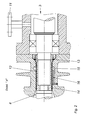
- das Detail "X" des Gegenstandes nach Fig. 1.
- Fig. 1
- a schematic partially sectioned side view of a centrifugal pump with a shaft gap seal according to the invention and
- Fig. 2
- the detail "X" of the article of FIG. 1.
In allen Figuren werden für gleiche bzw. gleichartige Bauteile übereinstimmende Bezugszeichen verwendet.In all figures the same reference numerals are used for identical or similar components.
Fig. 1 zeigt eine Kreiselpumpe 1 mit einer horizontal angeordneten angetriebenen Welle 2, die sich zwischen der Antriebsseite 3 und der Arbeitsseite 4 erstreckt.Fig. 1 shows a centrifugal pump 1 with a horizontally disposed driven
Die Antriebsseite 3 ist dabei eine gasgespülte Lagerseite und die Arbeitsseite 4 stellt die Mediumsseite, insbesondere Flüssigkeitsseite, mit einem Mediumseintritt 5 und Mediumsaustritt 6 dar.The
Die Antriebsseite 3 ist im dargestellten Ausführungsbeispiel hermetisch abgedichtet und mit einer Magnetkupplung 7 mit Spalttopf 8 versehen.The
Arbeitsseitig ist das Laufrad 9 der Kreiselpumpe 1 mit Rückenschaufeln 10 versehen.On the working side, the
Im dargestellten Ausführungsbeispiel ist oberseitig auf der angetriebenen Seite der Welle 2 die Sperrgaszufuhr 11 vorgesehen.In the illustrated embodiment, the sealing
Wie aus Fig. 2 ersichtlich, strömt das durch die Sperrgaszufuhr 11 eingeleitete Sperrgas an der Welle 2 vorbei in Richtung der Arbeitsseite 4, wobei es vor Eintritt in die Labyrinthdichtung 12 durch einen antriebsseitigen Wellendichtring 13 durchtritt. Die Labyrinthdichtung 12 besteht im dargestellten Ausführungsbeispiel aus einem an der Welle 2 angeordneten und sich mit dieser mitdrehenden Labyrinth 14, dem eine Auffangnut 15 im antriebsseitigen Bereich der Labyrinthdichtung 12 mit daran schließender Rückführleitung 16, die im arbeitsseitigen Bereich des Labyrinthes 14 mündet, zugeordnet ist.As can be seen from FIG. 2, the sealing gas introduced through the sealing
Claims (11)
Priority Applications (3)
| Application Number | Priority Date | Filing Date | Title |
|---|---|---|---|
| DE502005009371T DE502005009371D1 (en) | 2005-09-16 | 2005-09-16 | Shaft gap sealing |
| EP05020183A EP1764512B1 (en) | 2005-09-16 | 2005-09-16 | Shaft seal |
| AT05020183T ATE463674T1 (en) | 2005-09-16 | 2005-09-16 | SHAFT GAP SEALING |
Applications Claiming Priority (1)
| Application Number | Priority Date | Filing Date | Title |
|---|---|---|---|
| EP05020183A EP1764512B1 (en) | 2005-09-16 | 2005-09-16 | Shaft seal |
Publications (2)
| Publication Number | Publication Date |
|---|---|
| EP1764512A1 true EP1764512A1 (en) | 2007-03-21 |
| EP1764512B1 EP1764512B1 (en) | 2010-04-07 |
Family
ID=35768440
Family Applications (1)
| Application Number | Title | Priority Date | Filing Date |
|---|---|---|---|
| EP05020183A Active EP1764512B1 (en) | 2005-09-16 | 2005-09-16 | Shaft seal |
Country Status (3)
| Country | Link |
|---|---|
| EP (1) | EP1764512B1 (en) |
| AT (1) | ATE463674T1 (en) |
| DE (1) | DE502005009371D1 (en) |
Cited By (3)
| Publication number | Priority date | Publication date | Assignee | Title |
|---|---|---|---|---|
| CN105090079A (en) * | 2014-05-14 | 2015-11-25 | 江苏核电有限公司 | Large-sized mechanical seal assembly training and online detection platform |
| CN105201898A (en) * | 2015-10-24 | 2015-12-30 | 车晋绥 | Rubber pump novel water seal ring |
| CN112236006A (en) * | 2020-10-16 | 2021-01-15 | 安擎(天津)计算机有限公司 | Combined server rack structure and connecting method thereof |
Families Citing this family (1)
| Publication number | Priority date | Publication date | Assignee | Title |
|---|---|---|---|---|
| US11293554B2 (en) | 2017-03-09 | 2022-04-05 | Johnson Controls Technology Company | Back to back bearing sealing systems |
Citations (4)
| Publication number | Priority date | Publication date | Assignee | Title |
|---|---|---|---|---|
| US1867236A (en) * | 1926-05-03 | 1932-07-12 | Bbc Brown Boveri & Cie | Gas sealed gland |
| US2911919A (en) * | 1957-07-23 | 1959-11-10 | C H Wheeler Mfg Co | Pumping system |
| US2959133A (en) * | 1957-09-23 | 1960-11-08 | Allis Chalmers Mfg Co | Hermetically sealed pump motor unit |
| DE1293390B (en) * | 1957-05-28 | 1969-04-24 | Commissariat Energie Atomique | Device for sealing a centrifugal compressor used to compress a caustic, harmful and / or valuable gas |
-
2005
- 2005-09-16 AT AT05020183T patent/ATE463674T1/en active
- 2005-09-16 EP EP05020183A patent/EP1764512B1/en active Active
- 2005-09-16 DE DE502005009371T patent/DE502005009371D1/en active Active
Patent Citations (4)
| Publication number | Priority date | Publication date | Assignee | Title |
|---|---|---|---|---|
| US1867236A (en) * | 1926-05-03 | 1932-07-12 | Bbc Brown Boveri & Cie | Gas sealed gland |
| DE1293390B (en) * | 1957-05-28 | 1969-04-24 | Commissariat Energie Atomique | Device for sealing a centrifugal compressor used to compress a caustic, harmful and / or valuable gas |
| US2911919A (en) * | 1957-07-23 | 1959-11-10 | C H Wheeler Mfg Co | Pumping system |
| US2959133A (en) * | 1957-09-23 | 1960-11-08 | Allis Chalmers Mfg Co | Hermetically sealed pump motor unit |
Cited By (5)
| Publication number | Priority date | Publication date | Assignee | Title |
|---|---|---|---|---|
| CN105090079A (en) * | 2014-05-14 | 2015-11-25 | 江苏核电有限公司 | Large-sized mechanical seal assembly training and online detection platform |
| CN105090079B (en) * | 2014-05-14 | 2018-11-02 | 江苏核电有限公司 | Big machinery sealing assembly training and on-line checking platform |
| CN105201898A (en) * | 2015-10-24 | 2015-12-30 | 车晋绥 | Rubber pump novel water seal ring |
| CN112236006A (en) * | 2020-10-16 | 2021-01-15 | 安擎(天津)计算机有限公司 | Combined server rack structure and connecting method thereof |
| CN112236006B (en) * | 2020-10-16 | 2022-10-04 | 安擎(天津)计算机有限公司 | Combined server rack structure and connecting method thereof |
Also Published As
| Publication number | Publication date |
|---|---|
| DE502005009371D1 (en) | 2010-05-20 |
| ATE463674T1 (en) | 2010-04-15 |
| EP1764512B1 (en) | 2010-04-07 |
Similar Documents
| Publication | Publication Date | Title |
|---|---|---|
| EP0159464B1 (en) | Molecular vacuum pump | |
| EP1893898B1 (en) | Radial sealing device | |
| DE69719928T2 (en) | Rotary pump for liquids | |
| DE1811100B2 (en) | Sealing arrangement | |
| DE102016105309A1 (en) | Magnetic drive pump | |
| EP1764512B1 (en) | Shaft seal | |
| EP1859171A1 (en) | Oil-injected compressor with a temperature switch | |
| DE102005034341A1 (en) | Submerged motor pump has cooling sleeve for drive motor supplied with fluid from pumping wheel with flow throttling gap to discharge chamber | |
| DE102006058837A1 (en) | Lubricant-sealed rotary vane vacuum pump | |
| DE1653664A1 (en) | Self-priming centrifugal pump | |
| DE69914389T2 (en) | Sealing device for pumps | |
| EP0459107B1 (en) | Vacuum vane pump and its method of oil supply | |
| EP1343972A1 (en) | Method for operating a motor pump | |
| EP0386315A1 (en) | Sealing device and pump provided therewith | |
| DE19963170A1 (en) | Vacuum pump with shaft sealant | |
| EP0903500A2 (en) | Electrically driven coolant pump | |
| DE3007267A1 (en) | Helical rotor type vacuum pump - has packed type seals on rotor shafts with liquid cooling | |
| EP3061974B1 (en) | Cooling and degassing system for a heat transfer pump | |
| DE19809957A1 (en) | Multi-shaft vacuum pump | |
| EP1211422B1 (en) | Rotor of a canned motor for a canned motor pump | |
| EP0359136A1 (en) | Sealless centrifugal pump suited for cleaning | |
| EP2706236B1 (en) | Pump with dry running protection | |
| DE202016100655U1 (en) | Magnetic drive pump | |
| EP0920590A1 (en) | Dry vacuum machine with shaft passage | |
| DE342174C (en) | Sealing device for centrifugal pumps for pumping acids and other caustic liquids |
Legal Events
| Date | Code | Title | Description |
|---|---|---|---|
| PUAI | Public reference made under article 153(3) epc to a published international application that has entered the european phase |
Free format text: ORIGINAL CODE: 0009012 |
|
| 17P | Request for examination filed |
Effective date: 20061211 |
|
| AK | Designated contracting states |
Kind code of ref document: A1 Designated state(s): AT BE BG CH CY CZ DE DK EE ES FI FR GB GR HU IE IS IT LI LT LU LV MC NL PL PT RO SE SI SK TR |
|
| AX | Request for extension of the european patent |
Extension state: AL BA HR MK YU |
|
| AKX | Designation fees paid |
Designated state(s): AT BE BG CH CY CZ DE DK EE ES FI FR GB GR HU IE IS IT LI LT LU LV MC NL PL PT RO SE SI SK TR |
|
| 17Q | First examination report despatched |
Effective date: 20080310 |
|
| GRAC | Information related to communication of intention to grant a patent modified |
Free format text: ORIGINAL CODE: EPIDOSCIGR1 |
|
| GRAP | Despatch of communication of intention to grant a patent |
Free format text: ORIGINAL CODE: EPIDOSNIGR1 |
|
| GRAS | Grant fee paid |
Free format text: ORIGINAL CODE: EPIDOSNIGR3 |
|
| GRAA | (expected) grant |
Free format text: ORIGINAL CODE: 0009210 |
|
| AK | Designated contracting states |
Kind code of ref document: B1 Designated state(s): AT BE BG CH CY CZ DE DK EE ES FI FR GB GR HU IE IS IT LI LT LU LV MC NL PL PT RO SE SI SK TR |
|
| REG | Reference to a national code |
Ref country code: GB Ref legal event code: FG4D Free format text: NOT ENGLISH |
|
| REG | Reference to a national code |
Ref country code: CH Ref legal event code: EP |
|
| REG | Reference to a national code |
Ref country code: IE Ref legal event code: FG4D Free format text: LANGUAGE OF EP DOCUMENT: GERMAN |
|
| REF | Corresponds to: |
Ref document number: 502005009371 Country of ref document: DE Date of ref document: 20100520 Kind code of ref document: P |
|
| REG | Reference to a national code |
Ref country code: NL Ref legal event code: VDEP Effective date: 20100407 |
|
| RIN2 | Information on inventor provided after grant (corrected) |
Inventor name: MOELLMANN, HANS W. |
|
| PG25 | Lapsed in a contracting state [announced via postgrant information from national office to epo] |
Ref country code: SI Free format text: LAPSE BECAUSE OF FAILURE TO SUBMIT A TRANSLATION OF THE DESCRIPTION OR TO PAY THE FEE WITHIN THE PRESCRIBED TIME-LIMIT Effective date: 20100407 |
|
| LTIE | Lt: invalidation of european patent or patent extension |
Effective date: 20100407 |
|
| REG | Reference to a national code |
Ref country code: IE Ref legal event code: FD4D |
|
| PG25 | Lapsed in a contracting state [announced via postgrant information from national office to epo] |
Ref country code: ES Free format text: LAPSE BECAUSE OF FAILURE TO SUBMIT A TRANSLATION OF THE DESCRIPTION OR TO PAY THE FEE WITHIN THE PRESCRIBED TIME-LIMIT Effective date: 20100718 Ref country code: SE Free format text: LAPSE BECAUSE OF FAILURE TO SUBMIT A TRANSLATION OF THE DESCRIPTION OR TO PAY THE FEE WITHIN THE PRESCRIBED TIME-LIMIT Effective date: 20100407 Ref country code: NL Free format text: LAPSE BECAUSE OF FAILURE TO SUBMIT A TRANSLATION OF THE DESCRIPTION OR TO PAY THE FEE WITHIN THE PRESCRIBED TIME-LIMIT Effective date: 20100407 Ref country code: LT Free format text: LAPSE BECAUSE OF FAILURE TO SUBMIT A TRANSLATION OF THE DESCRIPTION OR TO PAY THE FEE WITHIN THE PRESCRIBED TIME-LIMIT Effective date: 20100407 |
|
| PGFP | Annual fee paid to national office [announced via postgrant information from national office to epo] |
Ref country code: IE Payment date: 20100916 Year of fee payment: 6 |
|
| PG25 | Lapsed in a contracting state [announced via postgrant information from national office to epo] |
Ref country code: FI Free format text: LAPSE BECAUSE OF FAILURE TO SUBMIT A TRANSLATION OF THE DESCRIPTION OR TO PAY THE FEE WITHIN THE PRESCRIBED TIME-LIMIT Effective date: 20100407 Ref country code: IS Free format text: LAPSE BECAUSE OF FAILURE TO SUBMIT A TRANSLATION OF THE DESCRIPTION OR TO PAY THE FEE WITHIN THE PRESCRIBED TIME-LIMIT Effective date: 20100807 Ref country code: LV Free format text: LAPSE BECAUSE OF FAILURE TO SUBMIT A TRANSLATION OF THE DESCRIPTION OR TO PAY THE FEE WITHIN THE PRESCRIBED TIME-LIMIT Effective date: 20100407 |
|
| PG25 | Lapsed in a contracting state [announced via postgrant information from national office to epo] |
Ref country code: GR Free format text: LAPSE BECAUSE OF FAILURE TO SUBMIT A TRANSLATION OF THE DESCRIPTION OR TO PAY THE FEE WITHIN THE PRESCRIBED TIME-LIMIT Effective date: 20100708 Ref country code: PL Free format text: LAPSE BECAUSE OF FAILURE TO SUBMIT A TRANSLATION OF THE DESCRIPTION OR TO PAY THE FEE WITHIN THE PRESCRIBED TIME-LIMIT Effective date: 20100407 Ref country code: CY Free format text: LAPSE BECAUSE OF FAILURE TO SUBMIT A TRANSLATION OF THE DESCRIPTION OR TO PAY THE FEE WITHIN THE PRESCRIBED TIME-LIMIT Effective date: 20100505 |
|
| PG25 | Lapsed in a contracting state [announced via postgrant information from national office to epo] |
Ref country code: PT Free format text: LAPSE BECAUSE OF FAILURE TO SUBMIT A TRANSLATION OF THE DESCRIPTION OR TO PAY THE FEE WITHIN THE PRESCRIBED TIME-LIMIT Effective date: 20100809 Ref country code: EE Free format text: LAPSE BECAUSE OF FAILURE TO SUBMIT A TRANSLATION OF THE DESCRIPTION OR TO PAY THE FEE WITHIN THE PRESCRIBED TIME-LIMIT Effective date: 20100407 Ref country code: DK Free format text: LAPSE BECAUSE OF FAILURE TO SUBMIT A TRANSLATION OF THE DESCRIPTION OR TO PAY THE FEE WITHIN THE PRESCRIBED TIME-LIMIT Effective date: 20100407 Ref country code: IE Free format text: LAPSE BECAUSE OF FAILURE TO SUBMIT A TRANSLATION OF THE DESCRIPTION OR TO PAY THE FEE WITHIN THE PRESCRIBED TIME-LIMIT Effective date: 20100407 |
|
| PLBE | No opposition filed within time limit |
Free format text: ORIGINAL CODE: 0009261 |
|
| STAA | Information on the status of an ep patent application or granted ep patent |
Free format text: STATUS: NO OPPOSITION FILED WITHIN TIME LIMIT |
|
| PG25 | Lapsed in a contracting state [announced via postgrant information from national office to epo] |
Ref country code: SK Free format text: LAPSE BECAUSE OF FAILURE TO SUBMIT A TRANSLATION OF THE DESCRIPTION OR TO PAY THE FEE WITHIN THE PRESCRIBED TIME-LIMIT Effective date: 20100407 Ref country code: CZ Free format text: LAPSE BECAUSE OF FAILURE TO SUBMIT A TRANSLATION OF THE DESCRIPTION OR TO PAY THE FEE WITHIN THE PRESCRIBED TIME-LIMIT Effective date: 20100407 Ref country code: RO Free format text: LAPSE BECAUSE OF FAILURE TO SUBMIT A TRANSLATION OF THE DESCRIPTION OR TO PAY THE FEE WITHIN THE PRESCRIBED TIME-LIMIT Effective date: 20100407 |
|
| 26N | No opposition filed |
Effective date: 20110110 |
|
| BERE | Be: lapsed |
Owner name: PAUL BUNGARTZ GMBH & CO. K.G. Effective date: 20100930 |
|
| PG25 | Lapsed in a contracting state [announced via postgrant information from national office to epo] |
Ref country code: IT Free format text: LAPSE BECAUSE OF FAILURE TO SUBMIT A TRANSLATION OF THE DESCRIPTION OR TO PAY THE FEE WITHIN THE PRESCRIBED TIME-LIMIT Effective date: 20100407 |
|
| PG25 | Lapsed in a contracting state [announced via postgrant information from national office to epo] |
Ref country code: BE Free format text: LAPSE BECAUSE OF NON-PAYMENT OF DUE FEES Effective date: 20100930 |
|
| PG25 | Lapsed in a contracting state [announced via postgrant information from national office to epo] |
Ref country code: BG Free format text: LAPSE BECAUSE OF FAILURE TO SUBMIT A TRANSLATION OF THE DESCRIPTION OR TO PAY THE FEE WITHIN THE PRESCRIBED TIME-LIMIT Effective date: 20100407 Ref country code: HU Free format text: LAPSE BECAUSE OF FAILURE TO SUBMIT A TRANSLATION OF THE DESCRIPTION OR TO PAY THE FEE WITHIN THE PRESCRIBED TIME-LIMIT Effective date: 20101008 |
|
| PG25 | Lapsed in a contracting state [announced via postgrant information from national office to epo] |
Ref country code: TR Free format text: LAPSE BECAUSE OF FAILURE TO SUBMIT A TRANSLATION OF THE DESCRIPTION OR TO PAY THE FEE WITHIN THE PRESCRIBED TIME-LIMIT Effective date: 20100407 |
|
| PG25 | Lapsed in a contracting state [announced via postgrant information from national office to epo] |
Ref country code: BG Free format text: LAPSE BECAUSE OF FAILURE TO SUBMIT A TRANSLATION OF THE DESCRIPTION OR TO PAY THE FEE WITHIN THE PRESCRIBED TIME-LIMIT Effective date: 20100707 |
|
| REG | Reference to a national code |
Ref country code: FR Ref legal event code: PLFP Year of fee payment: 12 |
|
| REG | Reference to a national code |
Ref country code: FR Ref legal event code: PLFP Year of fee payment: 13 |
|
| REG | Reference to a national code |
Ref country code: FR Ref legal event code: PLFP Year of fee payment: 14 |
|
| PGFP | Annual fee paid to national office [announced via postgrant information from national office to epo] |
Ref country code: MC Payment date: 20230918 Year of fee payment: 19 Ref country code: LU Payment date: 20230918 Year of fee payment: 19 Ref country code: GB Payment date: 20230921 Year of fee payment: 19 Ref country code: AT Payment date: 20230915 Year of fee payment: 19 |
|
| PGFP | Annual fee paid to national office [announced via postgrant information from national office to epo] |
Ref country code: FR Payment date: 20230918 Year of fee payment: 19 Ref country code: DE Payment date: 20230929 Year of fee payment: 19 |
|
| PGFP | Annual fee paid to national office [announced via postgrant information from national office to epo] |
Ref country code: CH Payment date: 20231001 Year of fee payment: 19 |