EP1764146A2 - microporous filter membrane, method of making microporous filter membrane and separator employing microporous filter membranes - Google Patents
microporous filter membrane, method of making microporous filter membrane and separator employing microporous filter membranes Download PDFInfo
- Publication number
- EP1764146A2 EP1764146A2 EP20060076301 EP06076301A EP1764146A2 EP 1764146 A2 EP1764146 A2 EP 1764146A2 EP 20060076301 EP20060076301 EP 20060076301 EP 06076301 A EP06076301 A EP 06076301A EP 1764146 A2 EP1764146 A2 EP 1764146A2
- Authority
- EP
- European Patent Office
- Prior art keywords
- layer
- film
- filter
- support
- membrane
- Prior art date
- Legal status (The legal status is an assumption and is not a legal conclusion. Google has not performed a legal analysis and makes no representation as to the accuracy of the status listed.)
- Granted
Links
Images


Classifications
-
- B—PERFORMING OPERATIONS; TRANSPORTING
- B26—HAND CUTTING TOOLS; CUTTING; SEVERING
- B26F—PERFORATING; PUNCHING; CUTTING-OUT; STAMPING-OUT; SEVERING BY MEANS OTHER THAN CUTTING
- B26F1/00—Perforating; Punching; Cutting-out; Stamping-out; Apparatus therefor
- B26F1/26—Perforating by non-mechanical means, e.g. by fluid jet
- B26F1/31—Perforating by non-mechanical means, e.g. by fluid jet by radiation
-
- B—PERFORMING OPERATIONS; TRANSPORTING
- B01—PHYSICAL OR CHEMICAL PROCESSES OR APPARATUS IN GENERAL
- B01D—SEPARATION
- B01D63/00—Apparatus in general for separation processes using semi-permeable membranes
- B01D63/16—Rotary, reciprocated or vibrated modules
-
- B—PERFORMING OPERATIONS; TRANSPORTING
- B01—PHYSICAL OR CHEMICAL PROCESSES OR APPARATUS IN GENERAL
- B01D—SEPARATION
- B01D67/00—Processes specially adapted for manufacturing semi-permeable membranes for separation processes or apparatus
- B01D67/0002—Organic membrane manufacture
- B01D67/0023—Organic membrane manufacture by inducing porosity into non porous precursor membranes
- B01D67/0032—Organic membrane manufacture by inducing porosity into non porous precursor membranes by elimination of segments of the precursor, e.g. nucleation-track membranes, lithography or laser methods
- B01D67/0034—Organic membrane manufacture by inducing porosity into non porous precursor membranes by elimination of segments of the precursor, e.g. nucleation-track membranes, lithography or laser methods by micromachining techniques, e.g. using masking and etching steps, photolithography
-
- B—PERFORMING OPERATIONS; TRANSPORTING
- B01—PHYSICAL OR CHEMICAL PROCESSES OR APPARATUS IN GENERAL
- B01D—SEPARATION
- B01D69/00—Semi-permeable membranes for separation processes or apparatus characterised by their form, structure or properties; Manufacturing processes specially adapted therefor
- B01D69/02—Semi-permeable membranes for separation processes or apparatus characterised by their form, structure or properties; Manufacturing processes specially adapted therefor characterised by their properties
-
- B—PERFORMING OPERATIONS; TRANSPORTING
- B01—PHYSICAL OR CHEMICAL PROCESSES OR APPARATUS IN GENERAL
- B01D—SEPARATION
- B01D69/00—Semi-permeable membranes for separation processes or apparatus characterised by their form, structure or properties; Manufacturing processes specially adapted therefor
- B01D69/10—Supported membranes; Membrane supports
- B01D69/106—Membranes in the pores of a support, e.g. polymerized in the pores or voids
-
- B—PERFORMING OPERATIONS; TRANSPORTING
- B01—PHYSICAL OR CHEMICAL PROCESSES OR APPARATUS IN GENERAL
- B01D—SEPARATION
- B01D69/00—Semi-permeable membranes for separation processes or apparatus characterised by their form, structure or properties; Manufacturing processes specially adapted therefor
- B01D69/10—Supported membranes; Membrane supports
- B01D69/107—Organic support material
-
- B—PERFORMING OPERATIONS; TRANSPORTING
- B01—PHYSICAL OR CHEMICAL PROCESSES OR APPARATUS IN GENERAL
- B01D—SEPARATION
- B01D71/00—Semi-permeable membranes for separation processes or apparatus characterised by the material; Manufacturing processes specially adapted therefor
- B01D71/06—Organic material
- B01D71/58—Other polymers having nitrogen in the main chain, with or without oxygen or carbon only
- B01D71/62—Polycondensates having nitrogen-containing heterocyclic rings in the main chain
- B01D71/64—Polyimides; Polyamide-imides; Polyester-imides; Polyamide acids or similar polyimide precursors
-
- B—PERFORMING OPERATIONS; TRANSPORTING
- B23—MACHINE TOOLS; METAL-WORKING NOT OTHERWISE PROVIDED FOR
- B23K—SOLDERING OR UNSOLDERING; WELDING; CLADDING OR PLATING BY SOLDERING OR WELDING; CUTTING BY APPLYING HEAT LOCALLY, e.g. FLAME CUTTING; WORKING BY LASER BEAM
- B23K26/00—Working by laser beam, e.g. welding, cutting or boring
- B23K26/36—Removing material
- B23K26/38—Removing material by boring or cutting
- B23K26/382—Removing material by boring or cutting by boring
- B23K26/384—Removing material by boring or cutting by boring of specially shaped holes
-
- B—PERFORMING OPERATIONS; TRANSPORTING
- B01—PHYSICAL OR CHEMICAL PROCESSES OR APPARATUS IN GENERAL
- B01D—SEPARATION
- B01D2323/00—Details relating to membrane preparation
- B01D2323/42—Details of membrane preparation apparatus
-
- B—PERFORMING OPERATIONS; TRANSPORTING
- B01—PHYSICAL OR CHEMICAL PROCESSES OR APPARATUS IN GENERAL
- B01D—SEPARATION
- B01D2325/00—Details relating to properties of membranes
- B01D2325/02—Details relating to pores or porosity of the membranes
- B01D2325/028—Microfluidic pore structures
-
- Y—GENERAL TAGGING OF NEW TECHNOLOGICAL DEVELOPMENTS; GENERAL TAGGING OF CROSS-SECTIONAL TECHNOLOGIES SPANNING OVER SEVERAL SECTIONS OF THE IPC; TECHNICAL SUBJECTS COVERED BY FORMER USPC CROSS-REFERENCE ART COLLECTIONS [XRACs] AND DIGESTS
- Y10—TECHNICAL SUBJECTS COVERED BY FORMER USPC
- Y10S—TECHNICAL SUBJECTS COVERED BY FORMER USPC CROSS-REFERENCE ART COLLECTIONS [XRACs] AND DIGESTS
- Y10S55/00—Gas separation
- Y10S55/05—Methods of making filter
-
- Y—GENERAL TAGGING OF NEW TECHNOLOGICAL DEVELOPMENTS; GENERAL TAGGING OF CROSS-SECTIONAL TECHNOLOGIES SPANNING OVER SEVERAL SECTIONS OF THE IPC; TECHNICAL SUBJECTS COVERED BY FORMER USPC CROSS-REFERENCE ART COLLECTIONS [XRACs] AND DIGESTS
- Y10—TECHNICAL SUBJECTS COVERED BY FORMER USPC
- Y10T—TECHNICAL SUBJECTS COVERED BY FORMER US CLASSIFICATION
- Y10T428/00—Stock material or miscellaneous articles
- Y10T428/249921—Web or sheet containing structurally defined element or component
- Y10T428/249953—Composite having voids in a component [e.g., porous, cellular, etc.]
Landscapes
- Chemical & Material Sciences (AREA)
- Chemical Kinetics & Catalysis (AREA)
- Engineering & Computer Science (AREA)
- Physics & Mathematics (AREA)
- Optics & Photonics (AREA)
- Manufacturing & Machinery (AREA)
- Mechanical Engineering (AREA)
- Toxicology (AREA)
- General Health & Medical Sciences (AREA)
- Life Sciences & Earth Sciences (AREA)
- Forests & Forestry (AREA)
- Health & Medical Sciences (AREA)
- Plasma & Fusion (AREA)
- Separation Using Semi-Permeable Membranes (AREA)
- Filtering Materials (AREA)
- External Artificial Organs (AREA)
Abstract
Description
- The present invention relates generally to microporous membranes, to methods for making microporous membranes and to filtration or separation apparatus employing microporous membranes. More specifically, the present invention relates to microporous membranes of the type employing precisely dimensioned, micron-scale pores, and to methods for making such membranes and apparatus employing such membranes.
- Filters that discriminate based on size and/or shape are well known. One type of filter, for example, provides a tortuous path through which particles must navigate to pass through the filter. These are sometimes referred to as depth filters, and typically use a filter element made of a thick bed of fiber' or other material. Due to their thickness and tortuous path filtration technique, these filters sometimes require relatively high transmembrane, i.e. transfilter, pressures to facilitate flow through the filter, due to its thickness and the tortuous path filtration technique.
- In contrast to depth filters, another well-known type of filter employs relatively thin filter membranes, which typically have nominal pore sizes. Such membranes have been used in a wide variety of medical and industrial applications. For example, such filter membranes, with nominal pore size as low as 0.22 microns, have been used to filter bacteria and other matter from liquids, such as intravenous solutions. Such microporous filters also have been used to separate the cellular components of human blood (red cells, white cells and platelets) from liquid plasma in which the components are suspended. One well known device for carrying out such separation of blood components is the Autopheresis-C® separator, which is sold by Baxter Healthcare Corporation of Deerfield, Illinois.
- Although nominal pore size filter membranes have functioned generally satisfactorily, they tend to have limited porosity, discriminate principally on the' basis of size alone, and sometimes suffer from reduced flow rates due to blockage on the surface of the membrane. "Porosity," as used here, refers to the portion or percentage of the membrane surface made up of pores. This may also be referred to as the membrane "transparency." A high porosity or transparency filter membrane, i.e., one in which a large portion of its surface is made up of pores, tends to allow higher flow rates through the filter membrane at a given transmembrane pressure than a low porosity or transparency membrane, i.e., one in which a small portion of its surface is made up of pores.
- More recently, efforts have been directed to developing filter membranes having precise pore sizes and shapes for increased discrimination, particularly at the micron and sub-micron scale for the separation of, for example, cells and cell components. Such filters may have particular, but not exclusive, application in the separation of blood cells or other types of cells from one another or from the liquid (plasma in the case of blood cells) in which they are suspended.
- Filters with micron or smaller scale pores, however, often have significant limitations. One such filter membrane is referred to as a "trac-etched" membrane. A trac-etched membrane has holes or pores of uniform micron-scale diameter for discrimination based on particle size. However, trac-etched membranes typically have low porosity, which limits the amount of throughput or filtration rates.
- With trac-etched filters, for example, porosity tends to be between approximately two and six or seven percent. Attempts to increase porosity in trac-etched filter membranes often results in doublets or triplets, which are holes that overlap and therefore reduce the discrimination of the filter membrane. To avoid doublets or triplets, porosity in trac-etched membranes is typically limited to about seven percent and less.
- In addition to low porosity, trac-etched membranes have another drawback. Trac-etched membranes have only circular pores and are therefore not suitable for discriminating based on non-circular particle shape.
- More recently, it has been suggested to use lithographic microfabrication or similar micromachining techniques to provide filter membranes in which the pores have precise size and shape.
U.S. Patent No. 5,651 900 for example, discloses a particle filter made of inorganic material, such as silicon, that is suitable for use in high temperatures and with harsh solvents. The filter has precisely controlled pore sizes formed by interconnecting members, and has optional reinforcing ribs. - Precise pore size filter membranes have also been proposed, for example, for separating one class of blood cells from another.
U.S. patent application serial number 719,472 , entitled "Method and Apparatus for Filtering Suspensions of Medical and Biological Fluids or the Like", filed September 25 1996, and hereby incorporated by reference herein, describes such filter membranes having precise micron-scale and precision-shaped pores that can be used, for example, to separate red cells from white cells in human blood. - Experience has demonstrated, however, that the manufacture of microstructures, such as single-layer filter membranes by microlithography, micromachining or similar processes suffers from several constraints. As a "rule of thumb," for example, the diameter or largest transverse dimension of the pores can be no small er than about ½ or ⅓ the thickness of the membrane itself. Therefore, very small pore sizes, such as one micron or less, require very thin membranes of 2 to 3 microns or smaller in thickness. The inverse of this is commonly known as the "aspect ratio" and generally means that the thickness can be no more than about 2 or 3 times the pore size. Such very thin membranes, however, are typically very fragile and may not be sufficiently robust for some of the well known uses of microporous filter membranes.
- One such well known use is in the Autopheresis-C® plasmapheresis device sold by Baxter Healthcare Corporation of Deerfield Illinois. A detailed description of Autopheresis-C® device may be found in
U.S. Patent No. 5,194,145 to Schoendorfer , incorporated by reference herein. The Autopheresis-C® separator employs a microporous membrane mounted on a spinning rotor within a stationary housing. As described in the above patent, such a device is particularly efficient at separating blood cells from the plasma in which they are suspended. However, the microporous membrane used in such a device must be flexible and able to withstand the high rotational speeds, shear forces, and transmembrane pressures encountered in such a separation system. - As a result, microfabrication of microporous filter membranes has, in the past, been limited by competing considerations. On the one hand, finer filtration (smaller pore size) typically requires a filter membrane that is increasingly thin, and thus increasingly fragile. On the other hand, the desire for membrane robustness has generally been met by thicker membranes that do not typically permit the formation of high porosity very small, precisely controlled pores.
- As one answer to the issue of membrane fragility, it has been proposed to provide a filter membrane in which the membrane layer is located on a support layer.
U.S. patent No. 5,753,014. to Van Rijn describes a composite membrane having a polymeric membrane layer atop a separate polymeric macroporous support. The perforations or pores in the membrane layer and in the support are made by a micromachining process, such as a lithographic process in combination with etching. An intermediate layer may be deposited between the membrane and support for bonding enhancement and stress reduction. Although such a membrane may be suitable for some applications, it remains a relatively expensive membrane to fabricate, using small volume processes. - Very thin microporous membranes of micron-scale pores are also found in non-filtration applications. For example,
published International Application No. WO 96/10966, published April 18, 1996 - In any event, there remains a need for new or improved microporous filter membranes, for new or improved methods and processes for making such filter membranes, and for apparatus employing such membranes.
- In accordance with one aspect of the present invention, a monolithic polymeric filter membrane is provided that comprises a filter layer including micron-scale precision-shaped pores suitable for wide variety of filtration applications, and a support layer that includes a precision-shaped porous support structure for the filter layer. As discussed in more detail later, the filter membrane of the present invention may be fashioned from a single polymeric film or from multiple polymeric films that are joined, for example, by heat curing to form a single monolithic membrane with no discernible line of distinction between the filter and support layers. In either version, the present invention enables the filter layer to be very thin, which permits the formation of very small micron-scale precision-shaped pores, of relatively high porosity without resulting in undue membrane fragility.
- In a preferred embodiment of the filter membrane of the present invention, the support layer is thicker than the filter layer, and may be thicker than the filter layer by a factor of between about 2 and 250. Also, the support layer is preferably, but not necessarily, coextensive with the filter layer.
- A wide variety of support structures may be employed in the present invention to support and reinforce the filter layer of the membrane. In accordance with this invention, the support structure is precision-shaped and, therefore, may be configured to suit the particular needs for a given application. In one disclosed embodiment, the support structure is made up of a plurality of spaced apart support struts to support the filter layer. The support struts are preferably spaced apart a distance substantially greater than the size of the pores, to allow the filtrate passing through the filter layer to pass through the support structure relatively unimpeded. For example, the struts may be spaced apart a distance in the range of about 50 to 1000 microns, although other spacings may be used without departing from the broader aspects of the present invention. A second plurality of spaced apart support struts may also be used, intersecting the first plurality of support struts to define a support grid supporting the filter layer. Although the strut grid is currently preferred, other support structures, such as post and beam, suspension webs, and others also can be used to support the filter layer.
- In addition, the support structure also may comprise two or more layers or subgrids, for enhanced support and/or flexibility. The support layer, for example, may include one sublayer of selected porosity and another sublayer of different porosity between the filter layer and first-mentioned sublayer. The support layer may also include two or more subgrids of differing configuration. For example, in a support grid of the type employing spaced-apart struts, one subgrid could have struts of predetermined width and spacing and another subgrid could have struts of different width and/or spacing. As a further example, for supporting very thin filter layers, such as three microns or less, the subgrid directly supporting the filter layer could have more closely spaced struts that are not as wide as the struts in the other subgrid.
- Thus, it should be clear that the number and configuration of sublayers or subgrids may be varied, depending on the particular needs of the filter membrane in a given application. For reduced stress and ease of manufacture, for example, a support layer comprising a grid of intersecting walls may employ curves instead of sharp angles at the intersections. Carried a further step, this support structure could, in fact, be defined by a plurality of spaced apart, generally elliptical or cylindrical pores that extend through the grid thickness and create support walls or webs with a narrow waist area and wide intersecting area.
- The filter membrane of the present invention also may be made flexible. More particularly, the filter membrane of the present invention may be made sufficiently flexible to be disposed along a radius of curvature of about one-half inch, if desired. As will be described in greater detail later, this makes the filter membrane of present invention particularly suitable for application in rotating membrane separators, such as the earlier-mentioned Autopheresis-C® device, as well as other separators that require a non-planar, flexible filter membrane.
- Although suitable for applications such as the Autopheresis-C® separator and other medical applications, the filter membrane of the present invention is also suitable for wide variety of other applications where microporous membranes are used to filter liquids or suspensions, such as water or wine filtration and other industrial applications. Typically, although not necessarily, the micron-scale pores of the filter layer will be less than or equal to about twenty microns in their largest transverse dimension, although the particular size may be varied depending on the application. "Micron-scale" in this description means less than about 100 microns. "Precision-shaped" means a generally specific and predetermined shape, in contrast to the nominal pore size membranes of the prior art. "Precision-shaped" is intended to include and allow for varying degrees of precision, provided the general shape of the pore or other structure is a predetermined non-random shape.
- The exact pore size will depend on the desired application. For example, a filter membrane having pores less than or equal to about 0.22 microns in largest transverse (side-to-side) dimension would be suitable for filtering bacteria, as well as other matter of similar size, from liquid. A filter membrane in which the pore size is less than or equal to about 0.60-0.65 microns would be suitable for removing most cells and cell fragments from blood, leaving essentially cell-free plasma or, in a very different application, for filtering wine. A pore size of 0.45 microns or less can remove e-coli bacteria or be used for diagnostic and microscopy applications. A pore size of 0.08 microns may be used to filter water for electronic fabrication processes.
- The filter membrane of the present invention may also be made from a variety of materials and configurations that are suitable for microlithography or micromachining techniques. As noted above, the filter membrane of the present invention is monolithic, i.e., there is no reasonably discernible line of distinction between the layers or sublayers. Such a filter membrane may, for example, comprise layers made of materials that are different, but sufficiently compatible to be rendered monolithic by, for example, curing them together. Alternatively, a monolithic membrane results when the filter layer and support layer are defined on opposite sides of a single film.
- The material of the filter layer and support layer is preferably photosensitive (or photoimageable) and etchable (by dry or wet processes), although materials suitable for laser ablation or suitable for radiation based processing may also be used. The filter and support layers may be, but are not necessarily, made from the same type of materials, provided they can be made monolithic. Material suitable for dry etching, for example, may be used to form the filter layer because of the particularly good definition that results from dry etching. The support layer, on the other hand, is typically coarser than the filter layer, and the degree of definition less demanding - allowing photoimageable or laser ablatable materials to be used. Although photoimaging and laser ablation procedures typically do not provide definition as good as dry etching, such procedures are suitable for forming the precision-shaped pores of the filter layer for most anticipated applications.
- With laser ablation, each pulse of laser light removes only a small portion of polymeric material. Accordingly, laser ablation may be more suitable for forming the filter layer than the typically much thicker support layer. The support layer in such a membrane could be formed with other lithographic or micromachining processes, whether of single or multiple film construction.
- On the other hand, synchrotrons deliver highly directional x-ray radiation that can be used to unbond or "unzip" the polymer backbone of acrylic material, such as polymethyl methacrylate (PMMA). Using this concept, exposed areas of a polymer membrane, as defined by an x-ray mask having absorbing and transmitting sections defining the desired pattern, may be "unzipped" by ionizing radiation and subsequently developed away by solvent bath. This process may be used to form the filter layer, support layer, or both.
- As discussed in more detail later, the filter membrane may also be made from a film having the support layer embossed or pre-cast into one side, with the filter layer being formed using one or more of the above-described techniques for removing selected material from the other side of the film to define the filter layer.
- It is also contemplated that the pores of the integral membrane of the present invention may be non-circular if desired, and non-circular may be preferred for certain applications. For example, the pores may be elongated, as disclosed in the pending
U.S. application serial number 719,472 , to allow certain particles, such as red cells, to pass through and to block other particles, such as white cells. Depending on the application, other shapes may be desired, and the present invention lends itself particularly well to accommodating such varying needs. - As to materials for the filter and support layers, one preferred material for making the filter membrane is polyimide polymer. Polyimide polymers are available in photosensitive and etchable forms. A photosensitive polymer may be positive or negative. In negative-acting photosensitive polymers, the regions of the film that are exposed to light become fixed or permanent and the non-exposed regions of the film can be removed by chemical (solvent) treatment. In a positive-acting film, the portions of film exposed to light may be removed by chemical process, and the non-exposed regions remain fixed or permanent. The basic lithography and micromachining techniques for processing polymer membranes, such as polyimide photosensitive or etchable membranes, are well known, as shown for example in
Published International Application WO 96/10966 - The filter membrane of the present invention may be employed in a separator for separating particles such as, but not limited to, cells from a liquid or suspension. For example, in accordance with this further aspect of the present invention, a separator may be provided comprising a housing including a fluid inlet and a first fluid outlet, with a flow path defined in the housing between the inlet and first outlet. A monolithic polymeric filter membrane of the present invention may be located within the housing in the flow path to filter fluid (filtrate) passing therethrough. As described above, such membrane includes a filter layer with micron-scale precision-shaped pores through which filtrate may pass, and a support layer including a porous support structure for the filter layer.
- In such a separator, the filter membrane may be disposed in such a position and shaped as is reasonably needed for the particular application. For example, the filter membrane may be disposed across the flow path so as to filter particles, including but not limited to cells or cell fragments, from the liquid being filtered. Alternatively, the filter membrane may be positioned along the length of the flow path so that fluid from which filtrate is removed flows across the surface of the membrane. In this alternative, a second outlet would typically be provided to remove that portion of fluid not passing through the filter membrane.
- Because of the flexible, robust character, the membrane of the present invention, in one of its preferred forms, may be positioned in the separator in a curved disposition and, in fact, the membrane may be curved along a radius of curvature of about one―half inch. These characteristics of the membrane of present invention make it particularly suitable for use in the type of device that separates a liquid or suspension by passing it between two relatively rotating structures. Such a device is exemplified by the Autopheresis-C® separator sold by Baxter Healthcare Corporation.
- The Autopheresis-C® separator employs a generally cylindrical membrane-covered rotor within a generally cylindrical housing. A suspension, such as blood, is passed from one end of the housing to the other end, through a gap between the rotor and housing surfaces. Plasma flows through the membrane and exits through an outlet in the housing. As noted earlier, this has been found to be a very efficient device for separating the cellular components of human blood from the plasma in which they are suspended. It is, however, a relatively high stress environment in which the filter membrane must not only be flexible for mounting on the cylindrical rotor or housing, but have sufficient robustness to withstand the assembly or mounting of the membrane as well as the high-speed rotation of the rotor (several thousand rpm), the shear forces generated by the flowing fluid, and significant transmembrane pressure that may be employed to force filtrate to flow through the membrane (although with the high porosity, thin filter layer of the present invention, satisfactory filtrate flow rates may be obtained with lower transmembrane pressures than are presently used).
- One of the very unique aspects of the Autopheresis-C® device is that the relative rotation between the rotor and housing creates a series of strong vortex cells in the gap - known as Taylor Vortices. The Taylor Vortices sweep the surface of the membrane, helping to keep the membrane surface free of occluding particles (cells) and taking advantage of the membrane porosity. The high porosity membrane of the present invention, with the micron-scale precision-shaped pores, holds substantial promise for improving the already excellent performance of the Autopheresis-C® device.
- Therefore, in accordance with present invention, a separator may be provided for separating one or more components of liquid or suspension, which separator includes a housing defining a generally cylindrical interior surface and a rotor rotatably mounted within the housing and having a generally cylindrical outer surface spaced from the interior surface of the housing (or both). A flexible monolithic polymeric membrane in accordance with present invention may be disposed on the generally cylindrical surface' of the rotor or on the generally cylindrical interior surface of the housing (or both). Such membrane includes a filter layer having micron-scale precision-shaped pores and a support layer including a precision-shaped porous support structure for the filter layer. Whether mounted on the rotor or housing, the filter layer of the membrane would be positioned to face the space between the rotor and housing. In other words, if the filter membrane were mounted on the rotor, the filter layer would be facing the interior housing surface, and vice versa. The housing includes an inlet for introducing liquid or suspension, such as blood, into the housing and an outlet for removing a portion of the suspension from the space between the rotor and housing. To remove filtrate passing through the membrane, an additional outlet in housing is provided to communicate with the porous support layer side of membrane.
- In this rotary separator application, the filter membrane is curved to conform to the generally cylindrical surface of the rotor or housing on which it is disposed. This may require a radius of curvature as small as about one-half inch or thereabouts. As with the previously summarized separator, the size of the micron-scale pores of the filter membrane may be selected depending on the particular application or need.
- It is understood that the filter membrane employed in the separators summarized above may include the more particular features and aspects summarized above with respect to the membrane without the need to repeat all of them here. For example, the separator of the present invention may include a monolithic filter membrane in which the filter layer and support layer are separate layers joined to form a monolithic membrane or formed from a single film or sheet. Additional support sublayers or subgrids may be employed to enhance flexibility and/or strength, or different pore sizes or geometries may be used depending on the application.
- A further aspect of the present invention is directed to the method(s) for making a filter membrane of the type embodying the present invention. As indicated earlier, the filter membrane of the present invention, comprising a monolithic filter layer including micron-scale precision-shaped pores and a support layer including a precision-shaped support structure, may be formed from a single polymeric film or from different films that are joined together to form a monolithic filter membrane. The monolithic polymeric filter membrane of the present invention may be fashioned from a single film by removing selected material from one side of the polymeric film to define the micron-scale precision-shaped pores of the filter layer. Separately or simultaneously, the support structure may be formed by removing selected material from the other side of the film to define the porous support structure for the filter layer, the pores communicating with the porous support structure to allow the passage of filtrate therethrough.
- The filter membrane may be made monolithic by forming the filter and support layers from a single film or from separate films of the same or sufficiently compatible materials to allow the layers to become monolithic when bonded together. For example, the films may be non-fully cured when the pores and support structures are formed, and then cured together to form a monolithic membrane. When the filter membrane is made from two' or more separate films, the filter layer is formed by removing selected material from one polymeric film to define a plurality of micron-scale precision-shaped pores through the membrane. The support layer is formed by removing selected material from another polymeric film to define a precision-shaped porous support structure. The filter and support layers, and any additional or intermediate layers that may be required, are placed in overlying and contacting relation, and the layers are joined together to form the monolithic filter membrane.
- In accordance with another aspect of the present invention, the filter membrane may be formed from a single sheet of film in which the support structure is embossed or precast in one side of the sheet of film and one of the removal techniques discussed below used to remove selected material from the other side of the film to form the precision shaped pores.
- A variety of techniques may be used for removing material from the polymeric film, and the present invention in its broadest respects is not limited to any particular technique or combination of techniques. Techniques generally considered suitable for forming micron-scale precision-shaped pores and precision-shaped support structures include the microlithography and micromachining techniques of photoimaging, wet and dry etching, radiation based processing, such as radiation "unzipping," and laser ablation. "Wet etching" generally refers to etching by contact with liquid elements and "dry etching" generally refers to etching by contact with gas or plasma. Other micromachining techniques already existing or later developed may also be used.
- Although not all of these techniques have the same precision, they are all considered generally sufficiently precise for the present invention and for creating "precision shaped" pores and other structures. For example, laser light transmitted through a mask may be used to ablate the polymeric material of the film in selected areas defined by the mask. When the membrane is formed of a single film, laser ablation may be used to form either or both of the filter layer on one side of the film and the support layer on the other side of the film, simultaneously or sequentially.
- With an etchable polymeric film, such as a film of polyimide material, a metallic film may be applied to one surface of the polyimide film, and then a photoresist layer is added to the metallic film. A first pattern is created on the photoresist layer by light focused through a mask having the desired design to define micron-scale pores or the support structures. Selected material of the photoresist layer, depending on the pattern of exposure, is then removed by known chemical processing techniques. The metallic film, in the areas revealed after the removal of photoresist material, is next removed in accordance with well-known techniques. The removal of the photoresist material and metallic film in the selected areas reveals areas of the polymeric film corresponding to the pattern first created on the photoresist layer. These areas of polymeric film may be removed by various processes, but dry etching, such as reactive ion etching, is one preferred technique because of better definition or pattern transfer. The metal layer protects selected areas of the film from the etching process. After the etching process, the remainder of the photoresist material and metallic film are then removed from the polyimide film, exposing the filter layer or support layer with the desired structure. This technique may be used to form one or both layers of a single film or one or both layers of a membrane made from multiple films. It may also be combined with other techniques, such as laser ablation, radiation based processing, or embossing such that one layer is formed by one technique and another layer formed by another technique. Because of its good definition, dry etching or radiation based processing may be preferred techniques for removing materials to form the filter layer.
- Other techniques for forming the filter and support layers are also available with the present invention. The filter layer and/or support layer may comprise a photoimageable polymeric film and be formed by exposing the film to light through a mask that defines the pattern of the pores or support structure to be formed. Selected material of the film, depending on whether the film has positive or negative photoimageable properties, are then removed, as by solvent, to create the desired layer.
- Of course, laser ablation and etching may also be used as desired to form the various layers, sublayers, grids, subgrids and other features of the membrane as desired, without departing from the broader aspects of this invention. As discussed above, highly directional synchrotron x-ray radiation may also be used to unbond or unzip the polymer backbone of certain polymeric materials, for example, through a mask, to define the desired pattern of pores (or support structure), with the exposed positions being developed away in a solvent bath.
- In accordance with a further aspect of this invention, the filter membrane may be formed on a progressive, near continuous basis. In such a process, continuous web of polymeric film is continuously supplied. If photoimageable, a pattern is repeatedly, progressively created on the film by exposing one side to light through a mask. The film is then advanced through a solvent bath to remove selected material to form the filter or support layer. If the film is laser ablatable, laser light through a mask could be used to remove material in selected pattern from one or both sides of the film to form the filter and support layers. With photoimageable laser ablation or x-ray treatment methods, both layers of the filter and support can be formed simultaneously, or sequentially, on opposite sides of the membrane, with the result being a stepwise progressive, essentially continuous, manufacture of integral filter membrane of the present invention. Alternatively one side of the film could have an embossed or precast support structure, with one of the above techniques being employed to define the filter layer.
- Another method for making an integral filter membrane of the present invention involves manufacture of the membrane atop a substrate such as quartz or, preferably, a silicon wafer. In this method, if the substrate is a silicon wafer, the filter membrane is made by spinning a first photoimageable polymide layer onto the silicon wafer. The first polyimide layer is exposed to light through a mask defining a first pattern of one of the micron-scale pores or support structure. A second polyimide layer is then spun onto the first layer of polyimide so as to create an interface therebetween. The second polyimide layer is exposed to light through a mask defining a second pattern of the other of the micron-scale pores or the support structure. Selected material is removed from the first and second polyimide layers to define the micron-scale pores and support structure, and the first and second polyimide layers are cured together so as to remove the interface therebetween and create a monolithic filter layer-support structure. The monolithic filter layer-support structure is then removed from the silicon wafer substrate. The step of removing of selected material from the first polyimide layer may be carried out before the second layer is spun onto the first layer or after the second layer is spun and exposed.
- One more specific technique for making the filter membrane of the present invention on a silicon wafer substrate, in a batch type process, includes first spin coating polyimide material onto a substrate, such as a silicon wafer, after which a metal layer is applied, such as by sputtering, evaporation or vapor deposition, and a photoresist layer applied to the metal layer. The photoresist layer is developed by light exposure through a mask to define a first pattern of the micron-scale pores or the support structure. That pattern is transferred to the metal layer and subsequently transferred to the polyimide layer by selective removal of areas of the photoresist and metal layers to create the micron-scale pore'pattern for the filter layer or the support structure pattern for the support layer. The photoresist and metal layer are then removed, and a second polyimide layer spin coated onto the first layer. A second pattern is created on the second polyimide layer to define the other of the micron-scale pore pattern or the support structure. Selected material, as defined by the first and second pattern, is removed to create the other of the pore pattern or support structure. To form the monolithic filter membrane, the first and second polyimide layers, which are not fully cured, are cured together to remove any interface therebetween and create the monolithic filter membrane, which is then removed from the silicon wafer or other substrate.
-
- Figure 1 is a perspective view of a microporous membrane filter embodying the present invention.
- Figure 2 is a perspective view of the membrane filter of Figure 1 in which the filter and support layers are separated to show details of the support layer.
- Figure 3 is a top view of the membrane filter of Figure 1.
- Figure 4 is a sectional view of the filter membrane of Figure 3, taken along line 4-4 of Figure 3.
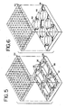
- Figure 5 is a perspective view of an alternative support structure for the membrane of the present invention, with curved intersections of the support walls or struts.
- Figure 6 is a perspective view of another alternate support structure defined by spaced apart cylindrical openings.
- Figure 7 is a perspective view of a membrane of the present invention in which the filter and support layers are separated to show a support layer of multiple sublayers or subgrids.
- Figures 8(a) and (b) are top and cross-sectional views of an alterative membrane of the present invention in which the pores are generally elongated.
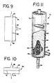
- Figure 9 is a cross-sectional view of a separator embodying the present invention.
- Figure 10 is a cross-sectional view of another separator embodying the present invention.
- Figure 11 is a perspective view of spinning membrane type filter embodying the present invention.
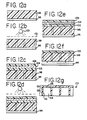
- Figures 12a-12g illustrate steps of one method for making a membrane of the present invention.
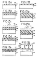
- Figures 13a-13i illustrate steps of another method for making a membrane of the present invention.
- Figure 14 illustrates a progressive near continuous process for making a membrane of the present invention.
- Figure 1 depicts a microporous polymeric filter membrane, generally at 20, embodying the present invention. In accordance with the present invention,
filter membrane 20 includes at least afilter layer 22 that includes a plurality of micron-scale precision-shapedpores 24, and asupport layer 26 that includes a precision-shaped support structure (better seen in Figure 2) for the filter layer, the filter and support layers being monolithic, in which there is no discernible line of distinction between the filter and support layers. As will be discussed in more detail later in connection with the method of making a membrane of the present invention, a monolithic membrane may be the result of forming the filter layer and support structure on opposite sides of a single film or forming the filter layer and support layer in different films that are either the same material or are different but sufficiently compatible material that they may be formed into a monolithic membrane, such as by forming the layers in an uncured or partially cured state and curing them together. - For purposes of illustration, the
filter membrane 20 shown in Figure 1 is not to scale. Although, theoretically, the support layer could be the same thickness as the filter layer, more typically thefilter layer 22 will be substantially thinner than thesupport layer 26. Preferably, the support layer is thicker than the filter layer by a factor of between about two and two hundred fifty. More specifically, the filter layer of the filter membrane of the present invention may be between about 0.3 and 3-5 microns thick, and the total filter membrane, including both filter layer and the support layer, may be between about 6 and 75 microns thick. In accordance with the present invention, however, the thickness of both filter layer and the support layer may be varied, depending on the desired pore size, the shape of pore, the degree of flexibility of the membrane that may be desired, as well as the amount of support desired for the filter layer. - One reason the filter layer is typically much thinner than the support layer is the general rule of thumb found in the manufacture of filter membranes by typical microfabrication techniques. As earlier mentioned, that rule of thumb is that the filter layer thickness, through which the pores extend, can be no greater than about 2 or 3 times the cross-sectional dimension of the pores. As noted earlier, this is called the "aspect ratio." For example, to form pores of 1 micron in cross-sectional dimension or diameter, the filter layer should be no thicker than about 2 or 3 microns.
- For purpose of this description, "micron-scale" pores means a pore size of about 100 microns or less. "Pore size" generally refers to the cross-sectional dimension of the pore, and not the depth of the pore through the filter layer. For pores of circular cross-sectional shape, pore size generally refers to the diameter of pore and for pores that are not circular, such as elongated pores, "pore size" generally refers to the smallest cross-sectional dimension of the pores, unless otherwise stated.
- It is presently contemplated that the pore size of a microporous filter membrane embodying present invention with typically be about 20 microns or less. The particular pore size may depend on the application to which the filter membrane is applied. For example, pore size of less than or equal to about 0.22 microns is smaller than bacteria and can remove bacteria from filtrate passing through the filter membrane. Pore size less than or equal to about 0.6 - 0. 65 microns may be used in biomedical applications to remove cells from human blood or in industrial applications, for example, to filter wine. A pore size of about 0.45 microns or less may be used to remove e-coli bacteria or may find application in diagnostic applications. A pore size of 0.08 microns may provide ultrafiltrated water suitable for electronic fabrication processes. A pore size of about 2 microns would allow platelets and plasma of human blood to pass through, but would block red cells and white cells.
- The density of the pores in the filter layer, or the "porosity" of the filter layer also may be selected accordingly to the intended application. In accordance with the present invention, the porosity of the filter layer may be substantially higher than found in earlier examples of micromachined filters, and the porosity may be as high as 30 percent or greater, allowing greater flow rates or "throughput" of filtrate through the filter membrane than previously obtained with the same or less transmembrane pressure.
- The
support layer 26 of thefilter membrane 20 of Figure 1 is best seen in Figure 2, in which the filter and support layers are shown separated. The illustratedsupport layer 26 includes spaced apart support struts orwalls 30 that are parallel and extend in one direction, and support walls or struts 32 that are parallel and extend perpendicular to supportwalls 30, and intersectingsupport walls 30 at junctions to define a support grid structure underlying the filter layer. The walls or struts 30 and 32 are preferably spaced apart a distance substantially greater than the cross-sectional dimension of the pores, as can readily be seen in Figures 1-8 and to 12. This creates a porous, coarser structure than found in the filter layer, allowing filtrate to readily pass through the support structure. The support struts orwalls - Figures 3 and 4 show other aspects of the filter membrane of Figure 1. Figure 3 is a top view, looking down on the filter layer and showing the pore layout in this version of the membrane. Figure 4 is a cross-sectional view of the
filter membrane 20. It is apparent from Figure 4 that the support structure is substantially coarser, with much greater porosity, than the filter layer. As noted above, this allows filtrate passing through the filter layer to pass readily through the support structure without any additional pressure loss or drag. - Turning now to Figure 5, an
alternate support structure 34 is shown that is similar to the support structure illustrated in Figure 2, except that the support walls or struts 30 and 32 are curved (or have fillets) 36 at the junctions where the walls or struts intersect. Although micromachining techniques have advanced significantly over the past decade, it remains very difficult to form surfaces at right angles as illustrated in Figure 2, and the structure of Figure 5 should be easier to fashion with micromachining processes. In addition, the use of curves or fillets at intersecting walls or struts also should tend to reduce stress and breakage in those areas when the membrane is flexed. - Figure 6 shows yet a further alternative support structure 38 in which the support walls or struts 30 and 32 are defined by circular openings through the support layer, in contrast to the rectangular openings of the Figures 2 and 5. This structure may be easier to fabricate than those shown in Figures 2 and 5. As result of circular openings, the support walls or struts have a generally
thinner waist area 42 and larger end areas 44 where intersecting the other support struts or walls. - The microporous filter membrane illustrated in Figures 1-6 has pores that are generally circular in cross-sectional shape. As noted earlier, in accordance with the present invention, the pores do not have the circular cross-sectional shape, and may have different shapes depending on the desired use. Figures 8 (a) and 8(b) are top and cross-sectional views, respectively, of an alternative membrane of the present invention in which the pores generally elongated in cross-sectional shape. More specifically, as shown in Figure 8 (a), the pores may be rectangular or oval in cross-sectional shape. This shape may provide greater porosity than circular pores, and is also particularly useful in the separation of red cells, platelets and plasma of human blood from white cells.
- This particular shape, however, is not new to the present invention. As disclosed in pending
U.S. patent application serial No. 719, 472 , previously incorporated by reference, the filter membrane having oval shaped pores of approximately 3 microns by 12 microns may be used to allow the passage of red cells, platelets and plasma while blocking passage of the larger white cells. Other shapes, of course, could be used for filtering different particles, including but not limited to cells, based on the particular shape of the particle, as well as on the size of particle. - As noted above, it is believed that the filter layer of the present invention, due to the monolithic support structure may be made extremely thin, permitting the formation of very small pores, as small as from about 0.08-0.10 microns pore size. For this size pore, the filter layer may be as thin as about 0.3 microns or thereabouts. The support structure shown in Figures 1-6 may be suitable for pores of about 1 micron or larger. As the pore size and filter layer thickness become increasingly smaller, other support structure configurations may be required for support of the filter layer.
- As pore size becomes much smaller, and the filter layer limited in its thickness, a support layer may be required that is particularly suitable for supporting ultra thin filter layers. For example, the support layer may include two or more sublayers or subgrids of differing porosity, spacing or configuration to better support a very thin filter layer. For example, the support layer may include a subgrid of more closely spaced struts or walls situated between the filter layer and the support grid of the structure shown in Figure 2.
- To provide improved support for the filter layer, particularly for supporting ultra thin filter layers less than about 0.3 microns, the support layer may include two or more sublayers or subgrids 46 and 48 as shown in Figure 7. As shown there, the support layer has two sublayers in the form of rectangular grids. The first subgrid or
sublayer 46 is comparable in configuration to the support structure shown in Figure 2 and described above. The second sublayer orsubgrid 48 is located between thefirst sublayer 46 and thefilter layer 22. The support walls or struts 50 and 52 in the second subgrid are more closely spaced than in the first subgrid to provide additional filter layer support. - The porosity of the different sublayers or subgrids, as well as the configuration of the support structure, the spacing between support walls or struts, and the relative thickness of support walls or struts may be varied according to the application of the particular filter membrane. For example, to provide additional support for the filter layer, the second sublayer may have less porosity than the first sublayer for greater contact with and support of the filter layer. Another alternative is for the second sublayer to comprise a grid having the same or more closely spaced support wall s or struts, but with the support walls or struts being thinner and more flexible than in the first sublayer or subgrid, so that greater support is provided, but with the first and second grids having the same porosity. Although illustrated as a support layer having two sublayers or subgrids in Figure 7, the configuration of the support structure may be varied significantly from that shown in Figure 7 without departing from the present invention. For example, the support structure may comprise a plurality of support struts that are all parallel, a support grid of different configuration, such as triangular, diamond shaped, circular or other configuration may be selected for ease of manufacture or for the enhanced membrane flexibility or filter layer support, or additional sublayers or subgrids could be provided.
- The filter membrane of the present invention may be used in a variety of applications. Figures 9 and 10 are provided to illustrate schematically at least two different types of filter devices or separators in which a membrane of present invention may be used. These examples are provided simply by way of illustration, and not limitation. The separator or filter apparatus in Figure 9 includes a housing 54 that may be made of any suitable material, such as rigid plastic or metal. The housing includes an
inlet 56, afirst outlet 58 and a second outlet 60. Afilter membrane 62 in accordance with the present invention is disposed so that fluid being filtered flows across the filter layer of themembrane 62. - Filtrate passing through the filter membrane is removed through the
first outlet 58 and the remaining fluid is removed through the second outlet 60. The shear forces of fluid moving across the surface of the membrane should tend to sweep and clear the membrane of clogging particles. The flow path across the membrane may be relatively small in cross-sectional size to cause an increase in flow velocity, enhancing any such sweeping or cleaning action. To further enhance fluid transfer, the transmembrane pressure between theinlet 56 andfirst outlet 58 may be maintained by appropriate and well-known pumps and pressure control systems to increase the throughput or flow rate of filtrate passing through the filter membrane. Of course, the filter housing may also include a rigid porous support frame or grid to support the membrane. - Another type of filter or separator in which the present membrane may be used is generically shown in Figure 10. Figure 10 illustrates a filter device or
separator 64 having ahousing 66 made of suitable material, with aninlet 68 and outlet 70. Afilter membrane 72 in accord with the present invention is provided in the housing in the flow path between the outlet and outlet. As a result of this arrangement, and unlike the separator of Figure 9, all of the fluid passing through the filter housing must pass through the filter membrane. A filter device or separator such as shown in Figure 10 may be used, for example, to remove bacteria or certain cells from liquid, or to remove particles greater than a certain size or of a certain shape. - The membrane of the present invention is preferably flexible. The monolithic combination of the filter membrane and the precision-shaped porous support structure provides, as required, both flexibility and robustness that permits the present invention to be used in higher stress filter applications, such as shown in Figure 11.
- Figure 11 is a perspective view of a spinning membrane type filter device of the type employed in the Autopheresis-C® plasmapheresis device marketed by Baxter Healthcare Corporation. The structure and operation of this separator are set forth in detail in
U. S . Patent No. 5,194,145 , previously incorporated by reference, and a detailed description will not be repeated here. Briefly, as depicted in Figure 11, the filter device orseparator 74 includes ahousing 76 defining a generally cylindricalinside surface 80. The housing includes afluid inlet 82, thefirst outlet 84 andsecond outlet 86. Arotor 88, with a generally cylindricalouter surface 90, is rotatably mounted in the housing with the outer surface of the rotor spaced from the interior surface of the housing to define asmall gap 92 therebetween. Thefilter membrane 94 of the present invention is mounted on the rotor, with the filter layer facing the gap located between the rotor and housing. The support layer of the filter membrane rests atop a series of spaced-apartsupport ribs 96 on the surface of the rotor. These raised support ribs support the membrane and form channels to collect filtrate passing through filter membrane.. - The flexibility of the membrane of the present invention allows it to be wrapped around the rotor and to conform to the surface of the generally cylindrically shaped rotor. With the membrane construction described in detail above, the membrane embodying the present invention is relatively flexible, and believed to sufficiently flexible to be flexed to radius of curvature of one-half inch. Although the membrane is shown on the surface of the rotor in Figure 11, alternatively, the membrane could be mounted on the generally cylindrical interior surface of the housing. In that event, the surface of the housing may similarly include raised ribs to support the filter membrane and to collect filtrate passing through the membrane.
- In either alternative of the separator shown in Figure 11, the filter membrane of the present invention is sufficiently robust to withstand the large shear and transmembrane pressures generated in a separator of this type, although the required transmembrane pressure may be significantly lower with the membrane of the present invention due to the reduced filter thickness and the higher porosity.
- In the separator shown in Figure 11, fluid such as a biological suspension or blood is introduced through
inlet 82 and flows down through thegap 92 between the outer surface of therotor 88 and inner surface of thehousing 76. During the passage through the gap, the high-speed rotation of rotor generates turbulence in the form of Taylor vortices, which sweep the membrane free of clotting cells or debris. Assisted by substantial transmembrane pressure generated by flow control pumps, plasma from the blood passes through the filter membrane and is collected in the channels defined between the spaced apart raisedribs 90. The plasma flows down through the channels into a collection manifold, and passes throughfirst outlet 84. The remaining portion of the fluid or suspension is withdrawn from the housing through thesecond outlet 86. In accordance with present invention, the characteristics of high porosity, micron-scale precision shaped pores in the filter layer, and filter membrane robustness hold significant promise for improved performance of the Autopheresis-C® device as well as potential new uses for such a separator. - The membrane of the present invention may be made from a variety of materials and one or more different micromachining techniques may be used to form the precision shaped pores or support structure of membrane. Figure 12 shows the steps involved in one method for making a filter membrane of the present invention in a batch-type process, in which the filter membrane is made on a substrate such as silicon wafer. First, as shown in Figure 12a, a substrate, such as
silicon wafer 96 with a layer of silicon dioxide (SiO), is provided. This silicon dioxide layer will later be sacrificed to remove the filter membrane created on the wafer. - As depicted in Figure 12a, a film of
photoimageable polyimide polymer 98, which will eventually become the support layer of the filter membrane, is spin coated to a thickness of, for example, about 30 microns, on top of thesilicon wafer 96. The polyimide layer is pre-baked or soft-baked to about 200°F for approximately one minute to partially cure the polyimide layer sufficiently to allow manipulation of it. - Referring to Figure 12b, the polyimide layer is in exposed to deep ultraviolet light 100, through a quartz/chrome mask 101 (which may be formed with well known processes) to define the structure of the support layer. If the polyimide material is positive-acting, the exposed areas are rendered permanent, through crosslinking, as result of light exposure. The areas that not exposed may be removed, as by solvent, at a later point in the process.
- After the support layer is formed, but before the material is removed to define the support structure, another layer of
polyimide material 102 is spin coated onto the first layer of material, as shown in Figure 12C. This layer, which will eventually form the filter layer, is relatively thin. It may typically be 1-3 microns thick, although it may also be as thin as about 0.3 microns. The polyimide material used for this layer is an etchable type of polyimide, and not a photoimageable polyimide. After this second layer of polyimide is formed, it is subjected to a soft bake procedure, as described above, to partially cure the newly added polyimide layer. A thin film ofmetal 104, such as titanium, is then added to the surface of the thin polyimide layer through a sputtering, evaporation or vapor deposition process. A very thin layer ofphotoresist material 106, such as one micron thickness, is then spincoated onto the metal layer, and a further softbake procedure carried out. - As shown in Figure 12d, the photoresist layer is then exposed to a deep ultraviolet light through a quartz mask to form a pattern in the photoresist corresponding to the desired pores. Development of the photoresist removes the photoresist material in those areas desired to define a pore structure. The effect of this developing is to expose the metal film in those areas where filter layer material is to be removed to define the filter pores.
- Employing an etching procedure, such as reactive ion etching or plasma etching, the exposed portions of the metal layer and the polyimide material therebelow in the thin polyimide layer are sequentially removed to define the pores of the filter layer as depicted in Figure 12e. The residual photoresist and metal layer may then be removed by solvent or chemical etching, resulting in a two layer preform -- the filter layer with precision-shaped micron-scale pores and the support layer, which still does not have the material removed to define a support structure, as shown in Figure 12f.
- Although the
photoimageable layer 98 is sitting on the silicon wafer, access to those areas that have not been cross-linked is available through the pores of the filter layer. By subjecting the preform to an appropriate solvent, the selected material of the support layer may be removed. The remaining polyimide layers are then subjected to a final cure at a full bake temperature such as 400°F for a period of hours to fully cure the polyimide material. Because the filter and support layers were not previously fully cured and are of compatible polyimide materials, during the curing process the layers chemically bond or cross-link, and the previous line of distinction between the layers disappears, and a monolithic filter membrane is formed as best seen in Figure 12g. After the baking process, the filter membrane is removed from the wafer by submerging the silicon wafer in a hydrofluoric acid bath, which attacks the silicon dioxide layer and releases the completed filter membrane (See Figure 12f) . - Alternatively, the filter membrane layers could be formed in reverse order, with filter layer first formed on a silicon wafer or other substrate. This process is shown in Figure 13. A thin layer of
etchable polyimide material 108 is spin coated onto the substrate, asilicon wafer 110. This layer of polyimide material will eventually form the filter layer of the filter membrane. After a soft bake, as shown in Figure 13b, a thin film layer ofmetal 112, such as titanium, is then formed atop the polyimide layer, and a layer ofphotoresist material 113 is spin coated onto the metal film. After a soft bake, the photoresist is exposed todeep UV light 114 through a quartz/chrome mask 116 (Figure 13c) to form a pattern corresponding to the desired pore arrangement. The photoresist is then developed to define the pore pattern, as shown in Figure 13d. Etching, such as by a reactive ion etching or plasma etching, may be used to transfer the corresponding pattern to themetal layer 112 and to thepolyimide layer 108 therebelow (Figure 13e). - The photoresist and metal layers are then removed from the filter layer, as by solvent, leaving the filter layer atop the silicon wafer (Figure 13f). As illustrated in Figure 13g, a thicker layer of
photoimageable polyimide material 118 is then spin coated onto the filter layer. This layer will eventually form the support layer of the filter membrane. After a soft bake, the thicker layer is exposed, as shown in Figure 13h, to deep UV light through a quartz/chrome mask 120 to define the precision-shaped support structure of the filter membrane in the thick polyimide layer. Selected material, depending on whether the photoimageable polyimide layer is positive or negative acting, is then removed, as by solvent, leaving the support structure atop the filter layer on the silicon wafer. The films are then subjected to a hard 400°F bake to fully cure the films. As a result of a hard bake, the compatible films of polyimide material join to form a monolithic membrane, which may be lifted from the silicon wafer by immersion in an acidic bath, leaving the finished filter membrane as shown in Figure 13i. - Still another method of making a microporous filter membrane of the present invention is shown in Figure 14. Figure 14 shows what is essentially a continuous method for making a microporous filter membrane comprising the present invention. In the method of Figure 14, a continuous supply of film, such as a photoimageable film, laser ablatable or x-ray treatable film, is provided from a
supply reel 122. Thefilm 124 from the supply reel is fed to afirst imaging station 126. At the first imaging station, either the filter layer or support layer is formed in one side of the film by one of these processes, such as photoimaging or laser ablation. For example, if the film is photoimageable, one side of the film would be exposed todeep UV light 128 through amask 130 to define onto the film the particular pattern for the pores or the support structure, whichever is being formed at this station. If a laser ablation process been used, the film is exposed to laser light, such as from an excimer laser, through themask 130 to ablate material from the film in selected areas to form the pore or support structure. Alternatively, a Synchrotron x-ray source and mask or other suitable micromachining process could be utilized. - The film is then moved or indexed to a second imaging station. 132, where a similar process is carried out on the other side of the film to form a pattern for the pores or support structure, whichever is not formed at the first station. As with the first station, the pores or support structure may be formed by laser ablation, x-ray, or a photoimaging process. From the second imaging station, the film passes through a
solvent bath 134, which would be required for a photoimaging or x-ray process, but not a laser ablation process, and then through a dryingstation 136 to the take-upreel 138. - It will be understood that it is not necessary that the same process be used at both imaging stations. For example, laser ablation or x-ray could be used at one station to form the filter layer, while a photoimaging process is used at the other station to form the support structure, or vice versa. The processes used at the imaging stations will, however, require that the film pause at those stations while the imaging or ablation is taking place. Thus, the process shown in Figure 14 is not continuous in the sense of continuous movement of the film, but it is a progressive stepwise process that continually produces microporous filter membrane incorporating the present invention, unlike the batch processes illustrated in Figures 12 and 13.
- One further alternative is the use of an embossed or precast film that would have, for example, one side of the film embossed or pre-cast with the courser support structure, where definition is less important. The support structure would presumably be embossed or pre-cast by rollers having a surface of raised and recessed area corresponding to the support structure and formed using known micromachining techniques.
- This procedure would eliminate one of the
exposure stations 128 in Figure 14. Only one station would be required to form the pores on the filter layer of the membrane using one of the photoimaging, ablation, x-ray, or other appropriate technique, such as described above. - The filter membrane of the present invention may be made from a variety of different materials. As pointed out above, one material particularly well suited for photoimaging or etching processes is polyimide polymer. These types of polymers are well known and, for example, are available from E.I. Du Pont de Nemours and Company of Wilmington, Delaware. Riston® material is an example of photoimageable film material available from du Pont in rollstock form, with a thickness of about 37 microns.
- The use of laser ablation also opens the door to the use of other materials other than polyimide polymers. For example, polycarbonate, acrylic, nylon, polytetrafluoroethylene, polyurethane, polyester, polypropylene, and polyvinyl chloride.
- The following is another specific example of a procedure carried out in making membranes of the present invention, based on use of a silicon wafer, batch process.
- 1. A standard six inch silicon wafer is provided as the substrate.
- 2. One micron of thermal oxide is grown in the wafer at 1000°C in a furnace for approximately 5 hours.
- 3. Polyimide (OLIN 114A) is spin-cast from a liquid solution onto the oxidized wafer at 3000 r.p.m. to create a film thickness of approximately 2.5 microns.
- 4. The resultant wafer with applied layers is hot plate baked-at 108°C for 90 seconds in order to firm up the polyimide somewhat.
- 5. The resultant wafer with applied layers is baked at 200°C for 1 hour in a Blue M oven; the polyimide is thereby partially cured.
- 6. A Titanium/Tungsten alloy layer is then applied to the layered structure by a technique such as sputtering, a well-known process in semiconductor and microstructure fabrication where high energy bombarding cause the dislodging and ejection to the gas phase of atoms from pure "targets;" the atoms subsequently travel through the evacuated chamber where they are collected on the surface of the substrate being processed to form a solid layer.
- 7. Photoresist (Hoechst AZ 5214) is spin coated onto the layered substrate at 3000 r.p.m. to a layer thickness of approximately 0.5 microns.
- 8. The layered substrate is exposed to light (wavelength of 436 nm) for 12 seconds via an OAI Contact mask aligner/exposion system. Located between the light source and the substrate is a quartz mask that contains a chrome pattern that exhibits the reverse polarity pattern of the desired filter layer geometric pattern. As such, the exposed light cross-links the negative-tone photoresist only in those regions where the light is available to the photoresist. The pattern mask contains solid chrome in those areas where holes would be desired on the filter membrane layer and no chrome where solid material would be desired, namely the areas between holes of the filter layer. The quartz/chrome mask is similar to those routinely used in lithographic processing in the semiconductor and microfabrication industries.
- 9. The exposed photoresist layer is then developed by 40 seconds of substrate immersion in a solution that is 3:1 by mass of Hoechst AZ 351 development solution to deionized water. The desired membrane pattern is thereby established in the photoresist layer.
- 10. The substrate and subsequently processed layers are then subjected to a de-ionized water rinse for 5 minutes.
- 11. The substrate and attached layers are then hot plate baked at 105°C for 5 minutes to drive off remaining water and further harden the remaining photoresist material by driving off remaining solvent.
- 12. The pattern developed in the photoresist layer is then faithfully transferred to the titanium/tungsten layer, which is now exposed in those areas where photoresist has been removed in the patterning process. This pattern transfer is done via reactive ion etching (RIE), a well-known process by which a substrate is subjected to a plasma that dissociates a relatively inert gas into reactive species that, assisted by ionic bombardment, etch the desired material. Here, a Plasmatherm 7200 Reactive Ion Etching System was used at 400 Watts and 40 mTorr vacuum with 90 sccm of CF4 and 10 sccm 02.
- 13. The pattern that had been transferred to the metal layer is now transferred to the polyimide layer, again using RIE via the PlasmaTerm 7200 RIE system at 40 mTor and 400 Watts with 80 sccm of 02 as the etching species. Since this oxygen etch basically removes all exposed organic compounds, the remaining photoresist is also removed during this step.
- 14. The remaining titanium/tungsten layer is now removed by again utilizing the same RIE step outlined in 12. At this point all that remains is the oxidized wafer and the patterned polyimide that will form the filter membrane layer of the bi-layer composite structure.
- 15. Negative-acting photoimagable polyimide (OCG 412) is then spincast onto the substrate at 2000 rpm to a thickness of 25 microns.
- 16. A hotplate bake of 5 minutes at 110°C is performed.
- 17. The photoimageable polyimide layer is then exposed to light for 60 seconds through a reverse polarity mask defining the support grid structure/pattern.
- 18. Immersion develop 5 minutes followed by two 30 second rinses in deionized water.
- 19. The system is then fully cured in a Blue M oven by ramping the temperature up to 400°C and holding the temperature at 400 for 30 minutes, and ramping the temperature back down to room temperature. This process fully cures the polyimide from both processing layers and joins the layers to form one monolithic block that is still mounted to the oxidized wafer..
- 20. The sample is then immersed in a 7:1 buffered oxide etch of 7 parts NH40H (ammonium hydroxide) to one part HF (hydrofluoric acid). The buffered HF solution dissolves the oxide layer on the silicon wafer, releasing the bi-layer membrane filter which floats to the top of the solution.
- 21. The structure is rinsed in a deionized water bath for several minutes, removed, and rinsed again in a fresh deionized water bath.
- 22. The structure is allowed to air dry prior to mounting or use.
- Although the present invention has been described in terms of the preferred and alternative embodiments, this is for purposes of illustration and not for the purpose of limiting the appended claims, which define the scope of the present invention. The words of the claims are intended to be interpreted in accordance with their normal usage, unless specifically defined herein. It is not intended that the words of the claims be limited to those specific features or steps described above that are not expressly called for by the words of the claims. For example, it is not intended that claims requiring a support grid be limited to a rectangular grid of intersecting walls or struts as shown for example in Figures 2 and 5. It would be apparent to any one of ordinary skill reading this description that other configurations of grids or grid support structures could be used without departing from the present invention. For these reasons the present invention is defined by the appended claims and not the specific features of this disclosure.
Claims (30)
- A method for making a monolithic polymeric filter membrane comprising at least a filter layer including micron-scale precision-shaped pores and a support layer including a precision-shaped porous support structure for the filter layer, the method comprising:forming the filter layer by removing selected material from one side of a polymeric film to define the micron-scale precision-shaped pores of the filter layer; andforming the support layer by removing selected material from the other side of said film to define the precision-shaped porous support structure, the pores communicating with the porous support structure to allow the passage of filtrate therethrough.
- The method of claim 1 in which at least one of said filter layer and support layer is formed by:providing a polymeric film that is of polyimide material;applying a metallic film to one surface of said polyimide film;applying a photoresist material to said metallic film;creating a first pattern on said photoresist layer to define micron scale pores or support structure and removing selected material from said photoresist layer;removing material from said metallic film in the areas where said photoresist material has been removed;removing selected material from the polyimide film in the areas where the metallic film has been removed to define the pores or support structure; andremoving any remaining photoresist material and the metallic film from the polyimide film.
- The method of claim 1 in which at least one of said filter layer and said support layer comprises a photo-imageable polymeric film and the at least one layer is formed by exposing the film to light through a mask defining a pattern and removing selected portions of said polymeric film defined by pattern to form the pores or support layer.
- The method of claim 3 in which said polymeric film is a negative-acting photo-imageable film and said removing is carried out by removing the non-exposed portions of said film.
- The method of claim 3 in which said film is a positive-acting photo-imageable film and said removing is carried out by removing the exposed portions of said film.
- The method of claim 2 in which the removing of selected material from the polyimide film is carried out by dry etching.
- The method of claim 1 in which at least one of the steps of removing material includes ablating the film by laser or treating the film with ionizing radiation.
- The method of claim 7 employing an excimer laser to ablate said film.
- The method of any one of claims 1 to 8 in which the support layer is thicker than the filter layer.
- The method of claim 9, wherein the support layer is thicker than the filter layer by a factor of between about 2 and 250.
- The method of any one of claims 3 to 5, wherein a continuous web of the photo-imageable polymeric film is continuously supplied and the pattern is progressively created on said film and selected material is progressively removed to define the pores or support structure.
- The method of claim 1 in which a continuous web of laser ablatable polymeric film is continuously supplied and selected material is progressively removed to define the pores or support structure.
- The method of any one of claims 3 to 5 and 11 in which said photo-imageable polymeric film comprises a polyimide.
- The method of any one of claims 1 to 13 in which the support structure comprises a first plurality of spaced apart support struts in which said struts are spaced apart a distance substantially greater than the size of said micron-scale pores.
- The method of claim 14 in which said support structure comprises a second plurality of spaced apart struts intersecting said first plurality of struts to define a support grid.
- The method of claim 14 or 15 in which said struts are spaced apart a distance in the range of from about 50 to 1000 microns.
- The method of any one of claims 14 to 16 in which the struts are between about 10 and 100 microns in width.
- The method of any one of claims 1 to 13 in which the support structure comprises a grid.
- The method of claim 1 in which the support structure comprises at least two sub-layers, a first sub-layer of a selected porosity and a second sub-layer of different porosity than the first sub-layer and disposed between the first sub-layer and the filter layer.
- The method of claim 18 in which the support grid comprises at least two sub-grids, a first sub-grid comprising struts of selected width and spaced apart a selected distance and a second sub-grid disposed between the first sub-grid and the filter layer, the second sub-grid including support struts of different width or spacing than the struts in the first sub-grid.
- The method of claim 18 in which the grid comprises a plurality of intersecting walls, said walls being curved at least at the intersections.
- The method of claim 21 in which the grid comprises a plurality of intersecting walls defined by spaced apart, generally cylindrically or elliptically shaped pores.
- The method of any one of claims 1 to 22 in which the filter membrane is flexible.
- The method of claim 23 in which the filter membrane is sufficiently flexible to be disposed along a radius of curvature of ½ inch.
- The method of claim 1 wherein the filter layer is formed by ablating selected areas of one side of the polymeric film to a first selected depth to define the micron-scale precision-shaped pores and the support layer is formed by ablating selected areas of the other side of the polymeric film to a second selected depth to define the porous precision-shaped support structure.
- The method of claim 25 in which the ablation is carried out by laser.
- A method for making a monolithic polymeric filter membrane comprising at least a filter layer including micron-scale precision-shaped pores and a support layer including a precision-shaped support structure for the filter layer, the method comprising:providing a polymeric film including a support structure defined on one side of the film;forming the filter layer by removing selected material from the other side of the polymeric film to define the precision-shaped micron-scale pores of the filter layer.
- The method of claim 27, wherein said support structure is embossed on said one side of said film.
- The method of claim 27, wherein said support structure is pre-cast on said one side of said film.
- The method of any one of claims 27 to 29, wherein said forming step is carried out by etching, laser ablation, photo-imaging or radiation.
Applications Claiming Priority (2)
| Application Number | Priority Date | Filing Date | Title |
|---|---|---|---|
| US45717399A | 1999-12-08 | 1999-12-08 | |
| EP20000982412 EP1194216B1 (en) | 1999-12-08 | 2000-12-05 | Method of making microporous filter membrane |
Related Parent Applications (2)
| Application Number | Title | Priority Date | Filing Date |
|---|---|---|---|
| EP20000982412 Division EP1194216B1 (en) | 1999-12-08 | 2000-12-05 | Method of making microporous filter membrane |
| EP00982412.9 Division | 2000-12-05 |
Publications (3)
| Publication Number | Publication Date |
|---|---|
| EP1764146A2 true EP1764146A2 (en) | 2007-03-21 |
| EP1764146A3 EP1764146A3 (en) | 2007-12-26 |
| EP1764146B1 EP1764146B1 (en) | 2011-09-07 |
Family
ID=23815730
Family Applications (2)
| Application Number | Title | Priority Date | Filing Date |
|---|---|---|---|
| EP20060076301 Expired - Lifetime EP1764146B1 (en) | 1999-12-08 | 2000-12-05 | Method of making microporous filter membrane |
| EP20000982412 Expired - Lifetime EP1194216B1 (en) | 1999-12-08 | 2000-12-05 | Method of making microporous filter membrane |
Family Applications After (1)
| Application Number | Title | Priority Date | Filing Date |
|---|---|---|---|
| EP20000982412 Expired - Lifetime EP1194216B1 (en) | 1999-12-08 | 2000-12-05 | Method of making microporous filter membrane |
Country Status (13)
| Country | Link |
|---|---|
| US (2) | US7442303B2 (en) |
| EP (2) | EP1764146B1 (en) |
| JP (2) | JP4712264B2 (en) |
| CN (2) | CN101362058B (en) |
| AR (1) | AR030542A1 (en) |
| AT (2) | ATE354430T1 (en) |
| AU (1) | AU780338B2 (en) |
| BR (1) | BR0008062A (en) |
| CA (1) | CA2361930A1 (en) |
| DE (1) | DE60033520T2 (en) |
| ES (1) | ES2282153T3 (en) |
| MX (1) | MXPA01008017A (en) |
| WO (1) | WO2001041905A1 (en) |
Cited By (3)
| Publication number | Priority date | Publication date | Assignee | Title |
|---|---|---|---|---|
| US7442303B2 (en) | 1999-12-08 | 2008-10-28 | Baxter International Inc. | Microporous filter membrane, method of making microporous filter membrane and separator employing microporous filter membranes |
| WO2014128073A1 (en) * | 2013-02-25 | 2014-08-28 | Siemens Aktiengesellschaft | Method for producing a microscreen |
| EP3851848A1 (en) * | 2020-01-20 | 2021-07-21 | Infineon Technologies AG | Micromechanical device with perforated membrane |
Families Citing this family (137)
| Publication number | Priority date | Publication date | Assignee | Title |
|---|---|---|---|---|
| US20030168396A1 (en) * | 1999-12-08 | 2003-09-11 | Jacobson James D. | Monolithic filter body and fabrication technique |
| US6982058B2 (en) | 1999-12-08 | 2006-01-03 | Baxter International, Inc. | Method for fabricating three dimensional structures |
| FR2834477B1 (en) * | 2002-01-07 | 2004-03-12 | Centre Nat Rech Scient | METHOD FOR MANUFACTURING A SHEET HAVING THROUGH PORES AND APPLICATION TO THE MANUFACTURE OF MICRON AND SUBMICRON FILTERS |
| EP1545749A4 (en) * | 2002-09-11 | 2009-03-18 | Univ Michigan | Ultrafiltration membrane, device, bioartificial organ and methods |
| DE10256848A1 (en) * | 2002-12-04 | 2004-07-08 | Sibylle Latza | Method and device for separating whole blood under gravity into an erythrocyte concentrate and plasma |
| US20040121120A1 (en) * | 2002-12-20 | 2004-06-24 | The Procter & Gamble Company | Apparatus for making a polymeric web exhibiting a soft and silky tactile impression |
| DE10353894B4 (en) * | 2003-07-11 | 2007-02-15 | Nft Nanofiltertechnik Gmbh | Filter element and method for its production |
| CA2541476A1 (en) * | 2003-10-15 | 2005-05-06 | Electro Scientific Industries, Inc. | Microporous filter |
| JP4455287B2 (en) * | 2003-12-26 | 2010-04-21 | キヤノン株式会社 | Method for manufacturing ink jet recording head |
| US20080248182A1 (en) * | 2004-05-03 | 2008-10-09 | Tjeerd Jongsma | Device with a Membrane on a Carrier, as Well as a Method for Manufacturing Such a Membrane |
| NL1026530C2 (en) * | 2004-06-30 | 2006-01-02 | Friesland Brands Bv | Membrane on a support, as well as a method for manufacturing such a membrane. |
| US7807063B2 (en) * | 2004-09-28 | 2010-10-05 | Giner Electrochemical Systems, Llc | Solid polymer electrolyte composite membrane comprising plasma etched porous support |
| US8962132B2 (en) | 2004-09-28 | 2015-02-24 | Giner, Inc. | Solid polymer electrolyte composite membrane comprising a porous support and a solid polymer electrolyte including a dispersed reduced noble metal or noble metal oxide |
| US7947405B2 (en) * | 2004-09-29 | 2011-05-24 | Giner Electrochemical Systems, Llc | Solid polymer electrolyte composite membrane comprising porous ceramic support |
| EP1721657A1 (en) * | 2005-05-13 | 2006-11-15 | SONY DEUTSCHLAND GmbH | A method of fabricating a polymeric membrane having at least one pore |
| JP2007252966A (en) * | 2006-03-20 | 2007-10-04 | Toshiba Corp | Membrane module and water treatment system |
| US20070221065A1 (en) * | 2006-03-23 | 2007-09-27 | Adisorn Aroonwilas | Heat recovery gas absorption process |
| US9403126B2 (en) | 2007-01-10 | 2016-08-02 | The Regents Of The University Of Michigan | Ultrafiltration membrane, device, bioartificial organ, and related methods |
| US20080190887A1 (en) * | 2007-02-08 | 2008-08-14 | Kleo Kwok | Manufacture filtration elements |
| US8790528B2 (en) | 2007-02-08 | 2014-07-29 | Kleo Kwok | Manufacture filtration elements |
| JP2010521291A (en) * | 2007-03-13 | 2010-06-24 | ユニバーシティ オブ ヒューストン | Device and method for producing a particulate filter having regularly spaced micropores |
| US7960708B2 (en) * | 2007-03-13 | 2011-06-14 | University Of Houston | Device and method for manufacturing a particulate filter with regularly spaced micropores |
| CN103394291B (en) | 2007-05-17 | 2016-12-07 | Emd密理博公司 | Membrane laminate |
| DE102007029444A1 (en) | 2007-06-22 | 2008-12-24 | Goedel, Werner A., Dr. | Porous diaphragm for separating particles, liquid drop or mixture of both from gas or liquid, has pores with diameter depending on distance of one of two diaphragm surfaces |
| DE102007029445A1 (en) | 2007-06-22 | 2008-12-24 | Werner A. Goedel | Hierarchically structured films and membranes manufacturing method, involves applying and coating printed fluid structures on substrate with lining fluid, and hardening lining fluid and/or vaporized volatile components |
| EP2082670A1 (en) * | 2008-01-24 | 2009-07-29 | Nestec S.A. | Exchangeable filter for beverage production device and beverage production device comprising such filter |
| WO2009131694A1 (en) * | 2008-04-23 | 2009-10-29 | Anthony Alexander | Porous medical dorsal column self anchoring lead |
| KR100907383B1 (en) * | 2008-04-29 | 2009-07-10 | 현대자동차주식회사 | Air damping engine mount |
| FR2931081B1 (en) * | 2008-05-14 | 2010-06-25 | Direction Et Pirorites | DEVICE FOR FILTRATION OF A COMPLEX LIQUID SUCH AS BLOOD, IN PARTICULAR APPLICABLE TO AN AUTOSFUSER |
| US20110215045A1 (en) * | 2008-06-24 | 2011-09-08 | Zhilian Zhou | High fidelity through hole film, and associated method |
| DE102008035772B4 (en) * | 2008-07-31 | 2015-02-12 | Airbus Defence and Space GmbH | Particle filter and manufacturing method thereof |
| US8105411B2 (en) * | 2008-08-28 | 2012-01-31 | Illinois Tool Works Inc. | Fluid filter system and method |
| ES2369114T3 (en) * | 2008-09-19 | 2011-11-25 | Pall Corporation | DEPTH FILTER SHEET MATERIAL AND METHOD FOR MANUFACTURING THE SAME. |
| WO2010062794A1 (en) * | 2008-11-26 | 2010-06-03 | Corning Incorporated | Coated particulate filter and method |
| US8652332B2 (en) * | 2009-01-09 | 2014-02-18 | Massachusetts Institute Of Technology | Liquid filtration using pressure difference across a hydrophobic membrane |
| WO2010085337A1 (en) * | 2009-01-21 | 2010-07-29 | Creatv Microtech, Inc. | Method of fabrication of micro and nanofilters |
| DE102009006064B4 (en) * | 2009-01-26 | 2013-04-11 | Technische Universität Chemnitz | Process for producing a microstructured film |
| WO2010097280A1 (en) * | 2009-02-27 | 2010-09-02 | Unilever Plc | A spray nozzle |
| EP2411129A4 (en) * | 2009-03-25 | 2013-04-10 | Univ Nanyang Tech | A filter |
| DE102009015562B4 (en) | 2009-03-30 | 2014-09-25 | Fraunhofer-Gesellschaft zur Förderung der angewandten Forschung e.V. | Fluid filter, filter device and filtering method |
| SG175043A1 (en) * | 2009-04-13 | 2011-11-28 | Entegris Inc | Porous composite membrane |
| NL2002870C2 (en) * | 2009-05-11 | 2010-11-15 | Fluxxion B V | Method and device for desorbing a component from a liquid into a gas. |
| EP2267446A1 (en) * | 2009-06-24 | 2010-12-29 | Roche Diagnostics GmbH | Spreading layer and method for producing an analysis element spreading layer |
| US11284616B2 (en) | 2010-05-05 | 2022-03-29 | Hemanext Inc. | Irradiation of red blood cells and anaerobic storage |
| US9199016B2 (en) | 2009-10-12 | 2015-12-01 | New Health Sciences, Inc. | System for extended storage of red blood cells and methods of use |
| TWI506070B (en) * | 2009-12-14 | 2015-11-01 | 3M Innovative Properties Co | Microperforated polymeric film and methods of making and using the same |
| US8201928B2 (en) * | 2009-12-15 | 2012-06-19 | Xerox Corporation | Inkjet ejector having an improved filter |
| US9494865B2 (en) | 2009-12-31 | 2016-11-15 | Cornell University | Microscopically structured polymer monoliths and fabrication methods |
| US11175279B2 (en) | 2010-05-03 | 2021-11-16 | Creatv Microtech, Inc. | Polymer microfilters, devices comprising the same, methods of manufacturing the same, and uses thereof |
| EP3777994A1 (en) * | 2010-05-03 | 2021-02-17 | Creatv Microtech, Inc. | Polymer microfilters and methods of manufacturing the same |
| SG185113A1 (en) * | 2010-05-04 | 2012-12-28 | Agency Science Tech & Res | A microsieve for cells and particles filtration |
| WO2012027582A1 (en) | 2010-08-25 | 2012-03-01 | New Health Sciences | Method for enhancing red blood cell quality and survival during storage |
| PT2635114T (en) | 2010-11-05 | 2020-06-16 | New Health Sciences Inc | Irradiation of red blood cells and anaerobic storage |
| RU2593254C2 (en) | 2010-12-28 | 2016-08-10 | Стэмфорд Девайсиз Лтд. | Photodefined aperture plate and its manufacturing method |
| US10195570B2 (en) * | 2011-01-07 | 2019-02-05 | Creative Micro Tech, Inc. | Fabrication of microfilters and nanofilters and their applications |
| DE102011017696A1 (en) * | 2011-04-28 | 2012-10-31 | Siemens Aktiengesellschaft | Microsieve and method of making a microsieve |
| US9029813B2 (en) | 2011-05-20 | 2015-05-12 | Asml Netherlands B.V. | Filter for material supply apparatus of an extreme ultraviolet light source |
| ES2923571T3 (en) | 2011-08-10 | 2022-09-28 | Hemanext Inc | Integrated leukocyte, oxygen and/or CO2 filtering and plasma separation device |
| WO2013028308A1 (en) * | 2011-08-22 | 2013-02-28 | Dow Global Technologies Llc | Composite membrane formed from polymer blend including self-assembling block copolymers |
| JP5518039B2 (en) * | 2011-12-28 | 2014-06-11 | 株式会社日立製作所 | Filter and manufacturing method thereof |
| KR101444991B1 (en) | 2012-01-10 | 2014-10-02 | 한양대학교 산학협력단 | Membrane having cylinderical penetration channel and method of manufacturing the same |
| JP6234379B2 (en) * | 2012-02-03 | 2017-11-22 | フェート・エンフェー (フラームス・インステリング・フーア・テクノロジシュ・オンダーゾエク・エンフェー) | Backwashable filter element |
| US10124300B2 (en) * | 2012-02-28 | 2018-11-13 | Massachusetts Institute Of Technology | Flux-enhanced hierarchical porous membrane for oil-water nanoemulsion separation |
| SG11201407448VA (en) * | 2012-05-16 | 2015-01-29 | Univ California | Low resistance microfabricated filter |
| BR112014027624B1 (en) * | 2012-06-11 | 2021-01-19 | Stamford Devices Ltd | method of making an aerosol forming orifice plate blade, orifice plate, aerosol forming device and orifice plate blade |
| KR101469142B1 (en) * | 2012-06-18 | 2014-12-04 | 서울대학교산학협력단 | Iso-pore membrane and process for manufacturing the same |
| US9976572B2 (en) * | 2012-09-26 | 2018-05-22 | Shimadzu Corporation | Vacuum pump protection net, method for manufacturing the same, and vacuum pump |
| US9907654B2 (en) * | 2012-12-11 | 2018-03-06 | Dr. H.C. Robert Mathys Stiftung | Bone substitute and method for producing the same |
| US10040018B2 (en) | 2013-01-09 | 2018-08-07 | Imagine Tf, Llc | Fluid filters and methods of use |
| DE102013203050A1 (en) * | 2013-02-25 | 2014-08-28 | Siemens Aktiengesellschaft | Producing microsieve useful for enrichment or extraction of cells from cell-containing body fluids, preferably blood, urine, biopsy fluid, saliva, comprises e.g. providing carrier, and applying polymer film on carrier |
| DE102013203046A1 (en) | 2013-02-25 | 2014-08-28 | Siemens Aktiengesellschaft | Method of making a microsieve |
| AU2014223165B2 (en) | 2013-02-28 | 2017-04-13 | Hemanext Inc. | Gas depletion and gas addition devices for blood treatment |
| US20160009048A1 (en) * | 2013-03-12 | 2016-01-14 | 3M Innovative Properties Company | Polymeric multilayer film and methods to make the same |
| WO2014142754A1 (en) * | 2013-03-13 | 2014-09-18 | Cellsievo Pte Ltd | Microsieve |
| KR101511374B1 (en) * | 2013-03-18 | 2015-04-10 | 한국과학기술연구원 | Membrane including macro-void support layer |
| US20140336029A1 (en) * | 2013-05-07 | 2014-11-13 | The Procter & Gamble Company | Process for laser puncturing holes into water-soluble films |
| US9728802B2 (en) | 2013-05-14 | 2017-08-08 | Giner, Inc. | Micromold methods for fabricating perforated substrates and for preparing solid polymer electrolyte composite membranes |
| KR102272976B1 (en) | 2013-12-12 | 2021-07-06 | 쓰리엠 이노베이티브 프로퍼티즈 캄파니 | Method of making polymeric multilayer films |
| US9956529B2 (en) * | 2014-04-03 | 2018-05-01 | New York University | Microfabricated ion-selective filter for filtration of ions and molecules |
| US9861920B1 (en) | 2015-05-01 | 2018-01-09 | Imagine Tf, Llc | Three dimensional nanometer filters and methods of use |
| WO2015177311A1 (en) | 2014-05-23 | 2015-11-26 | Stamford Devices Limited | A method for producing an aperture plate |
| US10730047B2 (en) | 2014-06-24 | 2020-08-04 | Imagine Tf, Llc | Micro-channel fluid filters and methods of use |
| JP6359895B2 (en) * | 2014-06-27 | 2018-07-18 | 東京応化工業株式会社 | Membrane filter |
| JP6460658B2 (en) * | 2014-06-27 | 2019-01-30 | 東京応化工業株式会社 | Membrane filter |
| CN104147950A (en) * | 2014-08-27 | 2014-11-19 | 胡权 | Porous membrane used for emulsification, preparation method and application thereof |
| US10124275B2 (en) | 2014-09-05 | 2018-11-13 | Imagine Tf, Llc | Microstructure separation filters |
| FR3032184B1 (en) * | 2015-02-03 | 2017-02-10 | Qualipac Sa | COMMUNICATION SYSTEM AND METHOD USING A CONTAINER FOR A COSMETIC OR PHARMACEUTICAL PRODUCT OR A WINE OR A SPIRITUAL AND TWO MOBILE TELECOMMUNICATION EQUIPMENT |
| US10758849B2 (en) | 2015-02-18 | 2020-09-01 | Imagine Tf, Llc | Three dimensional filter devices and apparatuses |
| KR20180012242A (en) | 2015-03-10 | 2018-02-05 | 뉴 헬스 사이언시즈 인코포레이티드 | Oxygen reduction disposable kit, device and method of use thereof |
| IL285359B2 (en) | 2015-04-23 | 2024-01-01 | Hemanext Inc | Anaerobic blood storage containers |
| CA2985799A1 (en) | 2015-05-18 | 2016-11-24 | New Health Sciences, Inc. | Methods for the storage of whole blood, and compositions thereof |
| US10118842B2 (en) | 2015-07-09 | 2018-11-06 | Imagine Tf, Llc | Deionizing fluid filter devices and methods of use |
| US10479046B2 (en) | 2015-08-19 | 2019-11-19 | Imagine Tf, Llc | Absorbent microstructure arrays and methods of use |
| US10429738B2 (en) * | 2015-09-30 | 2019-10-01 | Tokyo Ohka Kogyo Co., Ltd. | Filtration filter, filtration method, production method of purified liquid chemical product for lithography, and method of forming resist pattern |
| AU2016343276A1 (en) * | 2015-10-20 | 2018-05-10 | National Research Council Of Canada | Polymer membranes having open through holes, and method of fabrication thereof |
| US10668436B2 (en) | 2015-10-30 | 2020-06-02 | Simpore Inc. | Methods for creating fluidic cavities by transmembrane etching through porous membranes and structures made thereby and uses of such structures |
| CN105328351B (en) * | 2015-11-02 | 2017-06-23 | 西安康普瑞新材料科技有限公司 | Anion window screening film drilling method and micropore window screening film |
| CN105420086A (en) * | 2015-12-28 | 2016-03-23 | 苏州浚惠生物科技有限公司 | Single-cell positioning microporous membrane, application and single-cell automatic acquisition device |
| US11311842B2 (en) | 2015-12-28 | 2022-04-26 | Fenwal, Inc. | Membrane separation device having improved filtration velocity |
| US10137665B2 (en) | 2016-01-14 | 2018-11-27 | Tokyo Ohka Kogyo Co., Ltd. | Method for manufacturing laminate, and laminate |
| US10449283B2 (en) | 2016-04-29 | 2019-10-22 | Fenwal, Inc. | System and method for selecting and culturing cells |
| EP3238759B1 (en) | 2016-04-29 | 2019-07-17 | Fenwal, Inc. | System and method for processing, incubating and/or selecting biological cells |
| KR101674018B1 (en) * | 2016-05-16 | 2016-11-08 | (주)글로리바이오텍 | Hiv diagnosis method using cd4, cd8 cell information |
| EP3463466B1 (en) | 2016-05-27 | 2022-02-16 | Hemanext Inc. | Anaerobic blood storage and pathogen inactivation method |
| JP2018089593A (en) * | 2016-12-06 | 2018-06-14 | イビデン株式会社 | Filter membrane |
| US10274495B2 (en) | 2016-12-21 | 2019-04-30 | Fenwal, Inc. | System and method for separating cells incorporating magnetic separation |
| CN106944751A (en) * | 2017-05-11 | 2017-07-14 | 英诺激光科技股份有限公司 | A kind of filter membrane and laser-processing system using Laser Processing |
| US11150225B2 (en) * | 2017-12-22 | 2021-10-19 | Agilent Technologies, Inc. | Filters for liquid flow based devices and systems |
| RU2678016C1 (en) * | 2017-12-28 | 2019-01-22 | Акционерное общество "Государственный научный центр Российской Федерации - Физико-энергетический институт имени А.И. Лейпунского" | Filtering element |
| KR102056938B1 (en) * | 2018-01-26 | 2019-12-17 | (주)메타포어 | Membrane structure with matrix structure and biomolecule filter using the same |
| JP2019130457A (en) | 2018-01-30 | 2019-08-08 | イビデン株式会社 | Filter membrane |
| CN108905640B (en) * | 2018-07-24 | 2020-12-04 | 广州安方生物科技有限公司 | Three-dimensional self-aligned micropore array high-pass filter membrane and manufacturing method thereof |
| JP2020044500A (en) * | 2018-09-19 | 2020-03-26 | イビデン株式会社 | Filter membrane and filtration method using the filter membrane |
| JP2020044499A (en) * | 2018-09-19 | 2020-03-26 | イビデン株式会社 | Filter membrane and filtration method using the filter membrane |
| US11177498B1 (en) | 2018-10-15 | 2021-11-16 | Ampcera Inc. | Redox flow batteries, components for redox flow batteries and methods for manufacture thereof |
| US11819806B1 (en) | 2018-10-15 | 2023-11-21 | Ampcera Inc. | Methods for manufacturing a solid state ionic conductive membrane on a macro porous support scaffold |
| US11311820B2 (en) * | 2018-11-16 | 2022-04-26 | Magna Imperio Systems Corp. | Spacers for ion-exchange device |
| CN109554285A (en) * | 2018-12-29 | 2019-04-02 | 北京大学 | A kind of flexible microporous film and the cell separation apparatus using its preparation |
| WO2020227668A1 (en) * | 2019-05-09 | 2020-11-12 | The Research Foundation For The State University Of New York | Method and device for parallel single-cell processing |
| US11600853B1 (en) | 2019-05-14 | 2023-03-07 | Ampcera Inc. | Systems and methods for storing, transporting, and handling of solid-state electrolytes |
| US20210101117A1 (en) * | 2019-10-02 | 2021-04-08 | General Biologicals Corporation | Microfilter, manufacturing method and microfiltration unit |
| CN110775940B (en) * | 2019-10-31 | 2023-08-15 | 潍坊歌尔微电子有限公司 | Method for manufacturing MEMS sensor assembly, and MEMS sensor assembly manufactured by the method |
| EP4295949A1 (en) * | 2019-11-19 | 2023-12-27 | University of Cincinnati | Devices and methods for concentration of analytes |
| KR102299597B1 (en) * | 2019-12-27 | 2021-09-08 | 연세대학교 산학협력단 | Composited Membrane and Preparation Method thereof |
| US11439959B2 (en) * | 2020-04-07 | 2022-09-13 | Global Life Sciences Solutions Usa, Llc | Porous flat deformation-resistant membrane |
| US11786869B2 (en) | 2020-04-07 | 2023-10-17 | Global Life Sciences Solutions Usa Llc | Biocompatible high aspect-ratio porous membrane |
| WO2022031993A1 (en) * | 2020-08-07 | 2022-02-10 | The Regents Of The University Of California | Improved filtration membrane and methods of making and using the same |
| KR102373588B1 (en) * | 2020-09-03 | 2022-03-11 | 주식회사 볼트크리에이션 | polymer air filter and manufacturing method thereof |
| US11833477B2 (en) | 2020-10-09 | 2023-12-05 | Global Life Sciences Solutions Usa, Llc | Tangential flow cassette-HF emulation |
| US11896934B2 (en) | 2020-12-08 | 2024-02-13 | Global Life Sciences Solutions Operations Uk Limited | Porous polymeric membrane with tear prevention ring |
| CN114733351A (en) * | 2021-01-07 | 2022-07-12 | 瑞爱生医股份有限公司 | Red blood cell filtering device and system comprising same |
| WO2022168578A1 (en) * | 2021-02-05 | 2022-08-11 | 東レ株式会社 | Method for manufacturing laminate, method for manufacturing polymer thin film, and laminate |
| JP2022156771A (en) * | 2021-03-31 | 2022-10-14 | Agc株式会社 | Filter for capturing fine particle, and method for manufacturing filter for capturing fine particle |
| WO2022207613A2 (en) * | 2021-03-31 | 2022-10-06 | Global Life Sciences Solutions Usa Llc | Micropore membranes and methods of fabrication thereof using pillar templates |
| US11826710B2 (en) | 2021-03-31 | 2023-11-28 | Global Life Sciences Solutions Usa, Llc | Micropore membranes and methods of fabrication thereof using pillar templates |
| WO2023031041A1 (en) * | 2021-09-01 | 2023-03-09 | Global Life Sciences Solutions Usa Llc | Filter membrane, filter membrane assembly and flexible bag bioreactor |
| CN113771103A (en) * | 2021-09-15 | 2021-12-10 | 山东佳润新材料有限公司 | Cutting equipment is used in polymer film production |
Citations (4)
| Publication number | Priority date | Publication date | Assignee | Title |
|---|---|---|---|---|
| US5194145A (en) | 1984-03-21 | 1993-03-16 | William F. McLaughlin | Method and apparatus for separation of matter from suspension |
| WO1996010966A1 (en) | 1994-10-07 | 1996-04-18 | Baxter International Inc. | Porous microfabricated polymer membrane structures |
| US5651900A (en) | 1994-03-07 | 1997-07-29 | The Regents Of The University Of California | Microfabricated particle filter |
| US5753014A (en) | 1993-11-12 | 1998-05-19 | Van Rijn; Cornelis Johannes Maria | Membrane filter and a method of manufacturing the same as well as a membrane |
Family Cites Families (64)
| Publication number | Priority date | Publication date | Assignee | Title |
|---|---|---|---|---|
| BE789293Q (en) | 1970-12-07 | 1973-01-15 | Parke Davis & Co | MEDICO-SURGICAL DRESSING FOR BURNS AND SIMILAR LESIONS |
| MX152562A (en) | 1978-05-15 | 1985-08-29 | Pall Corp | IMPROVEMENTS TO THE PROCEDURE FOR PREPARING ALCOHOL INSOLUBLE, HYDROPHILIC AND UNCOATED POLYAMIDE RESIN MEMBRANES |
| US4579698A (en) | 1982-05-28 | 1986-04-01 | Amf, Inc. | Process for producing a microporous polymeric filter membrane with adjacent non-porous edge layers and a pleated filter element formed from the membrane |
| US4604208A (en) * | 1983-12-29 | 1986-08-05 | Chaokang Chu | Liquid filtration using an anionic microporous membrane |
| DE3546091A1 (en) | 1985-12-24 | 1987-07-02 | Kernforschungsz Karlsruhe | CROSS-CURRENT MICROFILTER |
| FR2607022B1 (en) * | 1986-11-20 | 1991-02-22 | Commissariat Energie Atomique | PRODUCTION OF ASYMMETRIC MICROPOROUS MEMBRANES BY DOUBLE IRRADIATION, AND MEMBRANES THUS OBTAINED |
| GB8628723D0 (en) | 1986-12-02 | 1987-01-07 | Bellhouse Brian John | Particle separation |
| NL8603278A (en) * | 1986-12-23 | 1988-07-18 | Stork Veco Bv | MEMBRANE WITH PERFORATIONS AND METHOD FOR MANUFACTURING SUCH MEMBRANE. |
| DE3704546A1 (en) * | 1987-02-13 | 1988-08-25 | Kernforschungsz Karlsruhe | METHOD FOR PRODUCING A FILTER AND FILTER PRODUCED THEREOF |
| US4797175A (en) | 1987-03-09 | 1989-01-10 | Hughes Aircraft Company | Method for making solid element fluid filter for removing small particles from fluids |
| FR2623100B1 (en) * | 1987-11-13 | 1991-04-05 | Commissariat Energie Atomique | MICROPOROUS MEMBRANE OBTAINED BY TWO-SIDED IRRADIATION AND METHOD FOR OBTAINING SAME |
| DE3742770A1 (en) | 1987-12-17 | 1989-06-29 | Akzo Gmbh | MICRO / ULTRAFILTRATION MEMBRANES WITH DEFINED PORO SIZE BY IRRADIATION WITH PULSE LASERS AND METHOD FOR THE PRODUCTION THEREOF |
| US5034229A (en) | 1988-12-13 | 1991-07-23 | Alza Corporation | Dispenser for increasing feed conversion of hog |
| JPH0360713A (en) | 1989-07-31 | 1991-03-15 | Sumitomo Electric Ind Ltd | Porous carbon membrane and its production |
| DE69106240T2 (en) | 1990-07-02 | 1995-05-11 | Seiko Epson Corp | Micropump and method of making a micropump. |
| ES2069896T3 (en) | 1990-07-10 | 1995-05-16 | Westonbridge Int Ltd | VALVE, METHOD TO PRODUCE SUCH VALVE AND MICROPUMP THAT INCORPORATES SUCH VALVE. |
| US5275725A (en) | 1990-11-30 | 1994-01-04 | Daicel Chemical Industries, Ltd. | Flat separation membrane leaf and rotary separation apparatus containing flat membranes |
| US5348788A (en) | 1991-01-30 | 1994-09-20 | Interpore Orthopaedics, Inc. | Mesh sheet with microscopic projections and holes |
| DE4103853C2 (en) * | 1991-02-08 | 1994-09-15 | Oxyphen Gmbh | Process for the production of polymer film filters |
| RU94019986A (en) * | 1991-12-09 | 1996-04-27 | Миннесота Майнинг энд Мануфактуринг Компани (US) | Microstructural membrane and method for its manufacture |
| US5876452A (en) | 1992-02-14 | 1999-03-02 | Board Of Regents, University Of Texas System | Biodegradable implant |
| US5256360A (en) | 1992-03-25 | 1993-10-26 | Panasonic Technologies, Inc. | Method of manufacturing a precision micro-filter |
| US5726026A (en) | 1992-05-01 | 1998-03-10 | Trustees Of The University Of Pennsylvania | Mesoscale sample preparation device and systems for determination and processing of analytes |
| NL9200902A (en) | 1992-05-21 | 1993-12-16 | Cornelis Johannes Maria Van Ri | CERAMIC MICROFILTRATION MEMBRANE AND METHOD FOR MANUFACTURING SUCH MEMBRANE. |
| US5492551A (en) | 1992-10-23 | 1996-02-20 | Wolfe; Michael | Air filter assembly |
| US5514378A (en) | 1993-02-01 | 1996-05-07 | Massachusetts Institute Of Technology | Biocompatible polymer membranes and methods of preparation of three dimensional membrane structures |
| US5294145A (en) * | 1993-04-27 | 1994-03-15 | Cheng Shu Yen | Handcart with means for holding a baggage container |
| US5728089A (en) | 1993-06-04 | 1998-03-17 | The Regents Of The University Of California | Microfabricated structure to be used in surgery |
| US5427663A (en) | 1993-06-08 | 1995-06-27 | British Technology Group Usa Inc. | Microlithographic array for macromolecule and cell fractionation |
| NZ269041A (en) | 1993-06-23 | 1998-02-26 | Univ Brown Res Found | Implantable encapsulation device having a cell-tight dry seal at an opening thereof |
| DE69426414T2 (en) | 1993-09-24 | 2001-05-03 | Takiron Co | IMPLANT MATERIAL |
| DE69431994T2 (en) | 1993-10-04 | 2003-10-30 | Res Int Inc | MICRO-MACHINED FLUID TREATMENT DEVICE WITH FILTER AND CONTROL VALVE |
| US5514150A (en) | 1994-03-03 | 1996-05-07 | Lsi Logic Corporation | Micromachined conveyor devices |
| US5798042A (en) | 1994-03-07 | 1998-08-25 | Regents Of The University Of California | Microfabricated filter with specially constructed channel walls, and containment well and capsule constructed with such filters |
| US5985328A (en) | 1994-03-07 | 1999-11-16 | Regents Of The University Of California | Micromachined porous membranes with bulk support |
| US5770076A (en) | 1994-03-07 | 1998-06-23 | The Regents Of The University Of California | Micromachined capsules having porous membranes and bulk supports |
| US5985164A (en) | 1994-03-07 | 1999-11-16 | Regents Of The University Of California | Method for forming a filter |
| US5591139A (en) | 1994-06-06 | 1997-01-07 | The Regents Of The University Of California | IC-processed microneedles |
| US5681568A (en) | 1994-08-19 | 1997-10-28 | Cambridge Neuroscience, Inc. | Device for delivery of substances and methods of use thereof |
| US5876187A (en) | 1995-03-09 | 1999-03-02 | University Of Washington | Micropumps with fixed valves |
| US6227809B1 (en) | 1995-03-09 | 2001-05-08 | University Of Washington | Method for making micropumps |
| JPH10503964A (en) | 1995-06-07 | 1998-04-14 | ゴア ハイブリッド テクノロジーズ,インコーポレイティド | Implantable containment device for a therapeutic device and method for loading and reloading the device therein |
| DE69619400T2 (en) | 1995-06-16 | 2002-09-26 | Univ Washington Seattle | FLAT MICROPRODUCED CROSS-FLOW FILTER FOR LIQUIDS |
| US5709798A (en) | 1995-06-19 | 1998-01-20 | Pall Corporation | Fibrous nonwoven web |
| US5849208A (en) | 1995-09-07 | 1998-12-15 | Microfab Technoologies, Inc. | Making apparatus for conducting biochemical analyses |
| US5997263A (en) | 1996-02-09 | 1999-12-07 | Westonbridge International Limited | Micromachined filter for a micropump |
| US6143948A (en) | 1996-05-10 | 2000-11-07 | Isotis B.V. | Device for incorporation and release of biologically active agents |
| US5919364A (en) | 1996-06-24 | 1999-07-06 | Regents Of The University Of California | Microfabricated filter and shell constructed with a permeable membrane |
| US5824204A (en) | 1996-06-27 | 1998-10-20 | Ic Sensors, Inc. | Micromachined capillary electrophoresis device |
| TW391881B (en) | 1996-09-25 | 2000-06-01 | Baxter Int | Method and apparatus for filtering suspensions of medical and biological fluids or the like |
| US6264044B1 (en) | 1997-04-11 | 2001-07-24 | Cuno, Inc. | Reinforced, three zone microporous membrane |
| US5938923A (en) | 1997-04-15 | 1999-08-17 | The Regents Of The University Of California | Microfabricated filter and capsule using a substrate sandwich |
| US5928207A (en) | 1997-06-30 | 1999-07-27 | The Regents Of The University Of California | Microneedle with isotropically etched tip, and method of fabricating such a device |
| US6146771A (en) | 1997-07-01 | 2000-11-14 | Terumo Cardiovascular Systems Corporation | Process for modifying surfaces using the reaction product of a water-insoluble polymer and a polyalkylene imine |
| US6129928A (en) | 1997-09-05 | 2000-10-10 | Icet, Inc. | Biomimetic calcium phosphate implant coatings and methods for making the same |
| US6187329B1 (en) | 1997-12-23 | 2001-02-13 | Board Of Regents Of The University Of Texas System | Variable permeability bone implants, methods for their preparation and use |
| WO1999064580A1 (en) | 1998-06-10 | 1999-12-16 | Georgia Tech Research Corporation | Microneedle devices and methods of manufacture and use thereof |
| GB9815820D0 (en) | 1998-07-22 | 1998-09-16 | Secr Defence | Improvements relating to micro-machining |
| CA2344398A1 (en) | 1998-09-18 | 2000-03-30 | The University Of Utah | Surface micromachined microneedles |
| US6333029B1 (en) | 1999-06-30 | 2001-12-25 | Ethicon, Inc. | Porous tissue scaffoldings for the repair of regeneration of tissue |
| US6520997B1 (en) | 1999-12-08 | 2003-02-18 | Baxter International Inc. | Porous three dimensional structure |
| MXPA01008017A (en) | 1999-12-08 | 2002-04-24 | Baxter Int | Microporous filter membrane, method of making microporous filter membrane and separator employing microporous filter membranes. |
| NL1016779C2 (en) | 2000-12-02 | 2002-06-04 | Cornelis Johannes Maria V Rijn | Mold, method for manufacturing precision products with the aid of a mold, as well as precision products, in particular microsieves and membrane filters, manufactured with such a mold. |
| US6500751B2 (en) | 2001-01-29 | 2002-12-31 | International Business Machines Corporation | Method of forming recessed thin film landing pad structure |
-
2000
- 2000-12-05 MX MXPA01008017A patent/MXPA01008017A/en active IP Right Grant
- 2000-12-05 EP EP20060076301 patent/EP1764146B1/en not_active Expired - Lifetime
- 2000-12-05 AU AU19446/01A patent/AU780338B2/en not_active Ceased
- 2000-12-05 WO PCT/US2000/032932 patent/WO2001041905A1/en active IP Right Grant
- 2000-12-05 JP JP2001543243A patent/JP4712264B2/en not_active Expired - Fee Related
- 2000-12-05 CN CN2008101304719A patent/CN101362058B/en not_active Expired - Fee Related
- 2000-12-05 DE DE2000633520 patent/DE60033520T2/en not_active Expired - Lifetime
- 2000-12-05 BR BR0008062A patent/BR0008062A/en not_active Application Discontinuation
- 2000-12-05 AT AT00982412T patent/ATE354430T1/en not_active IP Right Cessation
- 2000-12-05 ES ES00982412T patent/ES2282153T3/en not_active Expired - Lifetime
- 2000-12-05 CA CA 2361930 patent/CA2361930A1/en not_active Abandoned
- 2000-12-05 EP EP20000982412 patent/EP1194216B1/en not_active Expired - Lifetime
- 2000-12-05 AT AT06076301T patent/ATE523239T1/en not_active IP Right Cessation
- 2000-12-05 CN CN00803368A patent/CN1338970A/en active Pending
- 2000-12-07 AR ARP000106521 patent/AR030542A1/en unknown
-
2005
- 2005-08-02 US US11/195,025 patent/US7442303B2/en not_active Expired - Fee Related
-
2007
- 2007-11-27 JP JP2007306647A patent/JP2008086996A/en active Pending
-
2008
- 2008-09-16 US US12/211,400 patent/US7784619B2/en not_active Expired - Fee Related
Patent Citations (4)
| Publication number | Priority date | Publication date | Assignee | Title |
|---|---|---|---|---|
| US5194145A (en) | 1984-03-21 | 1993-03-16 | William F. McLaughlin | Method and apparatus for separation of matter from suspension |
| US5753014A (en) | 1993-11-12 | 1998-05-19 | Van Rijn; Cornelis Johannes Maria | Membrane filter and a method of manufacturing the same as well as a membrane |
| US5651900A (en) | 1994-03-07 | 1997-07-29 | The Regents Of The University Of California | Microfabricated particle filter |
| WO1996010966A1 (en) | 1994-10-07 | 1996-04-18 | Baxter International Inc. | Porous microfabricated polymer membrane structures |
Cited By (5)
| Publication number | Priority date | Publication date | Assignee | Title |
|---|---|---|---|---|
| US7442303B2 (en) | 1999-12-08 | 2008-10-28 | Baxter International Inc. | Microporous filter membrane, method of making microporous filter membrane and separator employing microporous filter membranes |
| US7784619B2 (en) | 1999-12-08 | 2010-08-31 | Baxter International Inc. | Method of making microporous filter membrane |
| WO2014128073A1 (en) * | 2013-02-25 | 2014-08-28 | Siemens Aktiengesellschaft | Method for producing a microscreen |
| US9442379B2 (en) | 2013-02-25 | 2016-09-13 | Siemens Aktiengesellschaft | Method for producing a microscreen |
| EP3851848A1 (en) * | 2020-01-20 | 2021-07-21 | Infineon Technologies AG | Micromechanical device with perforated membrane |
Also Published As
| Publication number | Publication date |
|---|---|
| ES2282153T3 (en) | 2007-10-16 |
| EP1194216A4 (en) | 2004-06-30 |
| US20090029142A1 (en) | 2009-01-29 |
| JP4712264B2 (en) | 2011-06-29 |
| ATE523239T1 (en) | 2011-09-15 |
| EP1764146B1 (en) | 2011-09-07 |
| EP1194216A1 (en) | 2002-04-10 |
| US20050263452A1 (en) | 2005-12-01 |
| AR030542A1 (en) | 2003-08-27 |
| CN1338970A (en) | 2002-03-06 |
| CN101362058A (en) | 2009-02-11 |
| CA2361930A1 (en) | 2001-06-14 |
| CN101362058B (en) | 2011-10-12 |
| ATE354430T1 (en) | 2007-03-15 |
| AU1944601A (en) | 2001-06-18 |
| AU780338B2 (en) | 2005-03-17 |
| DE60033520T2 (en) | 2007-06-21 |
| DE60033520D1 (en) | 2007-04-05 |
| US7784619B2 (en) | 2010-08-31 |
| MXPA01008017A (en) | 2002-04-24 |
| US7442303B2 (en) | 2008-10-28 |
| JP2008086996A (en) | 2008-04-17 |
| JP2003526497A (en) | 2003-09-09 |
| WO2001041905A1 (en) | 2001-06-14 |
| BR0008062A (en) | 2001-11-06 |
| EP1764146A3 (en) | 2007-12-26 |
| EP1194216B1 (en) | 2007-02-21 |
Similar Documents
| Publication | Publication Date | Title |
|---|---|---|
| EP1764146B1 (en) | Method of making microporous filter membrane | |
| US20100181288A1 (en) | Method of fabrication of micro- and nanofilters | |
| EP2268385A2 (en) | Manufacturing of nanopores | |
| JP4056559B2 (en) | Process for making micromachined structures and micromachined structures manufactured using such methods | |
| WO1995013860A1 (en) | Membrane filter and a method of manufacturing the same as well as a membrane | |
| US20040060867A1 (en) | Membrane support devices and methods of manufacturing | |
| WO2013043124A1 (en) | A multilayer filter | |
| EP2411129A1 (en) | A filter | |
| WO1993011861A1 (en) | Microstructured membranes and methods for making same | |
| JP6678238B2 (en) | Method of making a fluid cavity by transmembrane etching through a porous membrane and structures produced thereby and uses of such structures | |
| Tu et al. | Filtration of sub-100 nm particles using a bulk-micromachined, direct-bonded silicon filter | |
| US20180126311A1 (en) | Three dimensional nanometer filters and methods of use | |
| US20030168396A1 (en) | Monolithic filter body and fabrication technique | |
| WO2011142788A9 (en) | Microscopically structured polymer monoliths and fabrication methods | |
| TW200308013A (en) | Method for forming micro groove structure | |
| JP2019195756A (en) | Filter membrane | |
| Mustafa et al. | Design and Fabrication of Uniform Aluminium Pores for Planar Microfiltration System. | |
| JP2023537072A (en) | Improved filtration membrane and methods of making and using same | |
| RU2418621C1 (en) | Method of producing nanomembrane filters | |
| KR101417991B1 (en) | composite membranes consisted of metallic supporter and metal oxide membrane using metals patterned as prominent planes and depressed planes using lithography and their fabrication method | |
| JP2019195757A (en) | Filter membrane | |
| GB2403167A (en) | High flux filtration system | |
| Kuiper | microsieves |
Legal Events
| Date | Code | Title | Description |
|---|---|---|---|
| PUAI | Public reference made under article 153(3) epc to a published international application that has entered the european phase |
Free format text: ORIGINAL CODE: 0009012 |
|
| 17P | Request for examination filed |
Effective date: 20060713 |
|
| AC | Divisional application: reference to earlier application |
Ref document number: 1194216 Country of ref document: EP Kind code of ref document: P |
|
| AK | Designated contracting states |
Kind code of ref document: A2 Designated state(s): AT BE CH CY DE DK ES FI FR GB GR IE IT LI LU MC NL PT SE TR |
|
| RTI1 | Title (correction) |
Free format text: MICROPOROUS FILTER MEMBRANE, METHOD OF MAKING MICROPOROUS FILTER MEMBRANE AND SEPARATOR EMPLOYING MICROPOROUS FILTER MEMBRANES |
|
| PUAL | Search report despatched |
Free format text: ORIGINAL CODE: 0009013 |
|
| AK | Designated contracting states |
Kind code of ref document: A3 Designated state(s): AT BE CH CY DE DK ES FI FR GB GR IE IT LI LU MC NL PT SE TR |
|
| 17Q | First examination report despatched |
Effective date: 20080401 |
|
| AKX | Designation fees paid |
Designated state(s): AT BE CH CY DE DK ES FI FR GB GR IE IT LI LU MC NL PT SE TR |
|
| GRAP | Despatch of communication of intention to grant a patent |
Free format text: ORIGINAL CODE: EPIDOSNIGR1 |
|
| RTI1 | Title (correction) |
Free format text: METHOD OF MAKING MICROPOROUS FILTER MEMBRANE |
|
| GRAS | Grant fee paid |
Free format text: ORIGINAL CODE: EPIDOSNIGR3 |
|
| GRAA | (expected) grant |
Free format text: ORIGINAL CODE: 0009210 |
|
| REG | Reference to a national code |
Ref country code: GB Ref legal event code: FG4D |
|
| REG | Reference to a national code |
Ref country code: CH Ref legal event code: EP |
|
| REG | Reference to a national code |
Ref country code: IE Ref legal event code: FG4D |
|
| REG | Reference to a national code |
Ref country code: DE Ref legal event code: R096 Ref document number: 60046432 Country of ref document: DE Effective date: 20111103 |
|
| REG | Reference to a national code |
Ref country code: NL Ref legal event code: VDEP Effective date: 20110907 |
|
| PG25 | Lapsed in a contracting state [announced via postgrant information from national office to epo] |
Ref country code: FI Free format text: LAPSE BECAUSE OF FAILURE TO SUBMIT A TRANSLATION OF THE DESCRIPTION OR TO PAY THE FEE WITHIN THE PRESCRIBED TIME-LIMIT Effective date: 20110907 Ref country code: SE Free format text: LAPSE BECAUSE OF FAILURE TO SUBMIT A TRANSLATION OF THE DESCRIPTION OR TO PAY THE FEE WITHIN THE PRESCRIBED TIME-LIMIT Effective date: 20110907 |
|
| PG25 | Lapsed in a contracting state [announced via postgrant information from national office to epo] |
Ref country code: CY Free format text: LAPSE BECAUSE OF FAILURE TO SUBMIT A TRANSLATION OF THE DESCRIPTION OR TO PAY THE FEE WITHIN THE PRESCRIBED TIME-LIMIT Effective date: 20110907 Ref country code: GR Free format text: LAPSE BECAUSE OF FAILURE TO SUBMIT A TRANSLATION OF THE DESCRIPTION OR TO PAY THE FEE WITHIN THE PRESCRIBED TIME-LIMIT Effective date: 20111208 Ref country code: AT Free format text: LAPSE BECAUSE OF FAILURE TO SUBMIT A TRANSLATION OF THE DESCRIPTION OR TO PAY THE FEE WITHIN THE PRESCRIBED TIME-LIMIT Effective date: 20110907 |
|
| REG | Reference to a national code |
Ref country code: AT Ref legal event code: MK05 Ref document number: 523239 Country of ref document: AT Kind code of ref document: T Effective date: 20110907 |
|
| PG25 | Lapsed in a contracting state [announced via postgrant information from national office to epo] |
Ref country code: BE Free format text: LAPSE BECAUSE OF FAILURE TO SUBMIT A TRANSLATION OF THE DESCRIPTION OR TO PAY THE FEE WITHIN THE PRESCRIBED TIME-LIMIT Effective date: 20110907 |
|
| PG25 | Lapsed in a contracting state [announced via postgrant information from national office to epo] |
Ref country code: NL Free format text: LAPSE BECAUSE OF FAILURE TO SUBMIT A TRANSLATION OF THE DESCRIPTION OR TO PAY THE FEE WITHIN THE PRESCRIBED TIME-LIMIT Effective date: 20110907 Ref country code: IT Free format text: LAPSE BECAUSE OF FAILURE TO SUBMIT A TRANSLATION OF THE DESCRIPTION OR TO PAY THE FEE WITHIN THE PRESCRIBED TIME-LIMIT Effective date: 20110907 Ref country code: PT Free format text: LAPSE BECAUSE OF FAILURE TO SUBMIT A TRANSLATION OF THE DESCRIPTION OR TO PAY THE FEE WITHIN THE PRESCRIBED TIME-LIMIT Effective date: 20120109 |
|
| PLBE | No opposition filed within time limit |
Free format text: ORIGINAL CODE: 0009261 |
|
| STAA | Information on the status of an ep patent application or granted ep patent |
Free format text: STATUS: NO OPPOSITION FILED WITHIN TIME LIMIT |
|
| PG25 | Lapsed in a contracting state [announced via postgrant information from national office to epo] |
Ref country code: DK Free format text: LAPSE BECAUSE OF FAILURE TO SUBMIT A TRANSLATION OF THE DESCRIPTION OR TO PAY THE FEE WITHIN THE PRESCRIBED TIME-LIMIT Effective date: 20110907 Ref country code: MC Free format text: LAPSE BECAUSE OF NON-PAYMENT OF DUE FEES Effective date: 20111231 |
|
| REG | Reference to a national code |
Ref country code: CH Ref legal event code: PL |
|
| 26N | No opposition filed |
Effective date: 20120611 |
|
| REG | Reference to a national code |
Ref country code: IE Ref legal event code: MM4A |
|
| REG | Reference to a national code |
Ref country code: DE Ref legal event code: R097 Ref document number: 60046432 Country of ref document: DE Effective date: 20120611 |
|
| PG25 | Lapsed in a contracting state [announced via postgrant information from national office to epo] |
Ref country code: IE Free format text: LAPSE BECAUSE OF NON-PAYMENT OF DUE FEES Effective date: 20111205 Ref country code: CH Free format text: LAPSE BECAUSE OF NON-PAYMENT OF DUE FEES Effective date: 20111231 Ref country code: LI Free format text: LAPSE BECAUSE OF NON-PAYMENT OF DUE FEES Effective date: 20111231 |
|
| PG25 | Lapsed in a contracting state [announced via postgrant information from national office to epo] |
Ref country code: ES Free format text: LAPSE BECAUSE OF FAILURE TO SUBMIT A TRANSLATION OF THE DESCRIPTION OR TO PAY THE FEE WITHIN THE PRESCRIBED TIME-LIMIT Effective date: 20111218 |
|
| PG25 | Lapsed in a contracting state [announced via postgrant information from national office to epo] |
Ref country code: LU Free format text: LAPSE BECAUSE OF NON-PAYMENT OF DUE FEES Effective date: 20111205 |
|
| PG25 | Lapsed in a contracting state [announced via postgrant information from national office to epo] |
Ref country code: TR Free format text: LAPSE BECAUSE OF FAILURE TO SUBMIT A TRANSLATION OF THE DESCRIPTION OR TO PAY THE FEE WITHIN THE PRESCRIBED TIME-LIMIT Effective date: 20110907 |
|
| REG | Reference to a national code |
Ref country code: FR Ref legal event code: PLFP Year of fee payment: 16 |
|
| PGFP | Annual fee paid to national office [announced via postgrant information from national office to epo] |
Ref country code: GB Payment date: 20151229 Year of fee payment: 16 |
|
| PGFP | Annual fee paid to national office [announced via postgrant information from national office to epo] |
Ref country code: FR Payment date: 20151217 Year of fee payment: 16 |
|
| PGFP | Annual fee paid to national office [announced via postgrant information from national office to epo] |
Ref country code: DE Payment date: 20151229 Year of fee payment: 16 |
|
| REG | Reference to a national code |
Ref country code: DE Ref legal event code: R119 Ref document number: 60046432 Country of ref document: DE |
|
| GBPC | Gb: european patent ceased through non-payment of renewal fee |
Effective date: 20161205 |
|
| REG | Reference to a national code |
Ref country code: FR Ref legal event code: ST Effective date: 20170831 |
|
| PG25 | Lapsed in a contracting state [announced via postgrant information from national office to epo] |
Ref country code: FR Free format text: LAPSE BECAUSE OF NON-PAYMENT OF DUE FEES Effective date: 20170102 |
|
| PG25 | Lapsed in a contracting state [announced via postgrant information from national office to epo] |
Ref country code: DE Free format text: LAPSE BECAUSE OF NON-PAYMENT OF DUE FEES Effective date: 20170701 Ref country code: GB Free format text: LAPSE BECAUSE OF NON-PAYMENT OF DUE FEES Effective date: 20161205 |