EP1763982A1 - Landwirtschaftliches Bodenbearbeitungsgerät - Google Patents
Landwirtschaftliches Bodenbearbeitungsgerät Download PDFInfo
- Publication number
- EP1763982A1 EP1763982A1 EP06018910A EP06018910A EP1763982A1 EP 1763982 A1 EP1763982 A1 EP 1763982A1 EP 06018910 A EP06018910 A EP 06018910A EP 06018910 A EP06018910 A EP 06018910A EP 1763982 A1 EP1763982 A1 EP 1763982A1
- Authority
- EP
- European Patent Office
- Prior art keywords
- frame
- attachment
- elements
- point
- tower
- Prior art date
- Legal status (The legal status is an assumption and is not a legal conclusion. Google has not performed a legal analysis and makes no representation as to the accuracy of the status listed.)
- Granted
Links
Images


Classifications
-
- A—HUMAN NECESSITIES
- A01—AGRICULTURE; FORESTRY; ANIMAL HUSBANDRY; HUNTING; TRAPPING; FISHING
- A01B—SOIL WORKING IN AGRICULTURE OR FORESTRY; PARTS, DETAILS, OR ACCESSORIES OF AGRICULTURAL MACHINES OR IMPLEMENTS, IN GENERAL
- A01B49/00—Combined machines
-
- A—HUMAN NECESSITIES
- A01—AGRICULTURE; FORESTRY; ANIMAL HUSBANDRY; HUNTING; TRAPPING; FISHING
- A01B—SOIL WORKING IN AGRICULTURE OR FORESTRY; PARTS, DETAILS, OR ACCESSORIES OF AGRICULTURAL MACHINES OR IMPLEMENTS, IN GENERAL
- A01B59/00—Devices specially adapted for connection between animals or tractors and agricultural machines or implements
- A01B59/06—Devices specially adapted for connection between animals or tractors and agricultural machines or implements for machines mounted on tractors
- A01B59/066—Devices specially adapted for connection between animals or tractors and agricultural machines or implements for machines mounted on tractors of the type comprising at least two lower arms and one upper arm generally arranged in a triangle, e.g. three-point hitches
Definitions
- the invention relates to an agricultural cultivator according to the preamble of claim 1.
- Such tillage equipment are known.
- the cultivation tower is connected to the upper coupling elements by means of screw to the frame.
- the two lower coupling points of the three-point coupling elements are arranged on the frame.
- the lower links of an attachment stand for an order handler following the tillage device are to be arranged on additional coupling elements which are attached to the frame.
- the invention has for its object to provide a simple arrangement of the extension tower and the lower link of the attachment stand.
- a particularly lateral stable guidance of the lower link of the attachment linkage is achieved in that the attachment tower has at its two lower sides in each case one in the direction of travel and perpendicular outer surface that comes on these outer surfaces of the respective lower link of the attachment link to the plant.
- a position-safe arrangement of the attachment rod and the attachment tower to the device is achieved in that the connecting elements on the front and back of the frame each have two spaced-apart tabs, that the distance of the tabs of the common thickness of the lower link of the attachment link and the lower front Connecting element of the cultivation tower corresponds.
- front lower coupling elements for receiving the cultivation tower, the lower link of the attachment link and the lower three-point coupling elements is achieved in that the front spaced apart connecting plates are formed simultaneously as a receiving element for the bolt of the three-point coupling element of the harrow.
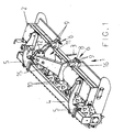
- the harrow 1 has the frame 2 with the tillage tools 3 arranged thereon. Behind the cultivator 1, a follower roller 4 is arranged by means of connecting arms 5. About the follower roller 4, the working depth of the tillage tools 3 of the harrow 1 is set. On the front side of the frame 2 and on the back of the frame 2, two mutually spaced connecting elements 6 and 7 are arranged in each case. The distance between the connecting elements 6,7 corresponds to the usual distance lower three-point coupling elements 8 for attachment to the three-point hitch of a tractor.
- the connecting elements 6,7 on the front and back of the frame 2 each have two spaced-apart tabs 9 and 10 respectively.
- a cultivation tower 11 on which the upper three-point coupling point 12 of the three-point coupling elements is arranged.
- the cultivation tower 11 has on its two lower sides in each case one in the direction of travel 13 and vertically extending outer surface 14. These outer surfaces 14 are located on the obliquely downwardly projecting struts 15 of the cultivation tower 11 arranged plate-like elements 16.
- the upper three-point coupling element 12 is thus at the extension tower 11 and the lower three-point coupling elements 8 are arranged on the frame 2 of the soil cultivation device 1.
- the front and the rear connecting straps 9, 10 have a plurality of openings arranged one above the other, can be plugged through the bolts 17.
- the plate-like element 16 of the attachment tower 11 has on the front and back respectively openings 18 which correspond to the distance to the upper opening 19 in the front connecting element 9 and the lower opening 20 in the rear connecting element 10.
- the cultivation tower 11 is connected via the through the apertures 18, 19 and 20 of the connecting plates 9,10 and the plate-like element 16 elongated pin 17 with the frame 2 of the device 1 and thus arranged on the frame 2.
- a spacer sleeve 21 is welded in each case.
- This spacer sleeve 21 has a width which corresponds to the inner spacing of the two lugs 10, the rear connecting elements 7.
- On the bolt 17 of the front connecting element 6, a spacer sleeve 22 is arranged so that the attachment tower 11 is laterally securely guided on the frame 2.
- the lower link 23 of a connecting linkage 24 for coupling an order machine on the back of the soil cultivation device 1 can be arranged on this coupling pin 17 at the front connecting elements 6.
- the spacing of the tabs 9 corresponds to the common thickness of the lower link 23 of the attachment link 24 and the lower front connecting element 16, namely the plate-like element 16 of the attachment tower 11.
- the respective lower link 23 of the attachment rod 24 comes to the plant.
- the lower link 23 of an attachment rod 24 for an order with the soil cultivating device 1 order device or in each case a spacer 22 are to be arranged on the front pin 17 of the coupling elements 6 either.
- the spaced apart on the back of the frame 2 tabs 10 of the connecting element 7 are arranged at a distance from each other, which corresponds to the thickness of the rear connecting element 16 of the attachment tower 11 and the thickness of the lower link 23 of the attachment rod 24 to each other.
- attachment rod 24 upper link 25 which is connected to the back of the upper pivot point of the attachment tower 11 by means of a bolt.
Landscapes
- Life Sciences & Earth Sciences (AREA)
- Engineering & Computer Science (AREA)
- Mechanical Engineering (AREA)
- Soil Sciences (AREA)
- Environmental Sciences (AREA)
- Zoology (AREA)
- Soil Working Implements (AREA)
- Agricultural Machines (AREA)
Abstract
Description
- Die Erfindung betrifft ein landwirtschaftliches Bodenbearbeitungsgerät gemäß des Oberbegriffes des Patentanspruches 1.
- Derartige Bodenbearbeitungsgeräte sind bekannt. Bei diesen bekannten Bodenbearbeitungsgeräten ist der Anbauturm mit den oberen Kupplungselementen mittels Schraubverbindungen mit dem Rahmen verbunden. Die beiden unteren Kupplungspunkte der Dreipunktkupplungselemente sind an dem Rahmen angeordnet. Die Unterlenker eines Anbaugestänges für ein dem Bodenbearbeitungsgerät nachfolgendes Bestellgerät sind an zusätzlichen Kuppelelementen, die an dem Rahmen befestigt sind anzuordnen.
- Der Erfindung liegt die Aufgabe zugrunde, eine einfache Anordnung des Anbauturmes und der Unterlenker des Anbaugestänges zu schaffen.
- Diese Aufgabe wird erfindungsgemäß durch die kennzeichnenden Merkmale des Patentanspruches 1 gelöst. Infolge dieser Maßnahmen wird eine wesentliche Vereinfachung der Anordnung des Anbauturmes auf dem Rahmen des Gerätes sowie die mögliche Anordnung des Anbaugestänges an dem Gerät zur Ankupplung nachfolgender Maschinen an das Gerät ermöglicht. Andererseits kann, wenn das Anbaugestänge nicht an dem Gerät angeordnet ist, durch die Anordnung der Distanzhülse eine lagesichere Befestigung des Anbauturmes auf dem Gerät sichergestellt werden. Durch die erfindungsgemäße Anordnung des Anbauturmes auf dem Gerät entfällt die aufwendige Verschraubung des Anbauturmes mit dem Rahmen des Gerätes und zusätzlicher Verbindungs- und Kuppelelemente zur Anordnung der Unterlenker des Anbaugestänges.
- Eine besonders seitenstabile Führung der Unterlenker des Anbaugestänges wird dadurch erreicht, dass der Anbauturm an seinen beiden Unterseiten jeweils eine in Fahrtrichtung und senkrecht verlaufende Außenfläche aufweist, dass an diesen Außenflächen der jeweilige Unterlenker des Anbaugestänges zur Anlage kommt.
- Eine lagesichere Anordnung des Anbaugestänges und des Anbauturmes an dem Gerät wird dadurch erreicht, dass die Verbindungselemente auf der Vorder- und Rückseite des Rahmens jeweils zwei beabstandet zueinander angeordnete Laschen aufweisen, dass der Abstand der Laschen der gemeinsamen Dicke des Unterlenkers des Anbaugestänges und des unteren vorderen Verbindungselementes des Anbauturmes entspricht.
- Eine vorteilhafte Ausgestaltung der vorderen unteren Kupplungselemente für die Aufnahme des Anbauturmes, der Unterlenker des Anbaugestänges sowie der unteren Dreipunktkupplungselemente wird dadurch erreicht, dass die vorderen beabstandet zueinander Verbindungslaschen gleichzeitig als Aufnahmeelement für den Bolzen des Dreipunktkupplungselementes des Bodenbearbeitungsgerätes ausgebildet sind.
- Eine gute seitliche Führung der Unterlenker des Anbaugestänges wird dadurch erreicht, dass auf der Rückseite des Rahmens ebenfalls zwei beabstandet zueinander angeordnete Laschen des Verbindungselementes angeordnet sind, die in dem Abstand der Dicke des hinteren Verbindungselementes des Anbauturmes und der Dicke des Unterlenkers des Anbaugestänges zueinander angeordnet sind.
- Weitere Einzelheiten der Erfindung sind den übrigen Unteransprüchen, der Beispielsbeschreibung und den Zeichnungen zu entnehmen. Hierbei zeigen
- Fig. 1
- das Bodenbearbeitungsgerät in perspektivischer Darstellung,
- Fig. 2
- das Bodenbearbeitungsgerät ausschnittsweise in perspektivischer Darstellung und in vergrößertem Maßstab,
- Fig. 3
- das Bodenbearbeitungsgerät ausschnittsweise in der Draufsicht,
- Fig. 4
- das Bodenbearbeitungsgerät mit Anbaugestänge für eine nachfolgende Bestellmaschine in perspektivischer Darstellung,
- Fig. 5
- das Bodenbearbeitungsgerät gemäß Fig. 4 in ausschnittsweiser und perspektivischer Darstellung,
- Fig. 6
- das Bodenbearbeitungsgerät gemäß Fig. 4 in ausschnittsweiser Darstellung und in der Draufsicht,
- Fig. 7
- das Bodenbearbeitungsgerät in ausschnittsweiser, perspektivischer und in teilweiser Explosionsdarstellung,
- Fig. 8
- das Bodenbearbeitungsgerät in perspektivischer Darstellung mit montiertem Anbauturm,
- Fig. 9
- das Bodenbearbeitungsgerät in ausschnittsweiser, in und perspektivischer Darstellung und in teilweiser Explosionsdarstellung,
- Fig. 10
- den linken vorderen Unterlenkeranlenkpunkt mit Distanzhülse in perspektivischer Darstellung und
- Fig. 11
- den linken vorderen Unterlenkeranlenkpunkt mit Unterlenker des Anbaugestänges in perspektivischer Darstellung.
- Das Bodenbearbeitungsgerät 1 weist den Rahmen 2 mit den daran angeordneten Bodenbearbeitungswerkzeugen 3 auf. Hinter dem Bodenbearbeitungsgerät 1 ist eine Nachlaufwalze 4 mittels Verbindungsarmen 5 angeordnet. Über die Nachlaufwalze 4 wird die Arbeitstiefe der Bodenbearbeitungswerkzeuge 3 des Bodenbearbeitungsgerätes 1 eingestellt. Auf der Vorderseite des Rahmens 2 und auf der Rückseite des Rahmens 2 sind jeweils zwei beabstandet zueinander angeordnete Verbindungselemente 6 und 7 angeordnet. Der Abstand der Verbindungselemente 6,7 entspricht dem üblichen Abstand unterer Dreipunktkupplungselemente 8 zum Anbau an den Dreipunktkraftheber eines Schleppers. Die Verbindungselemente 6,7 auf der Vorder- und Rückseite des Rahmens 2 weisen jeweils zwei beabstandet zueinander angeordnete Laschen 9 bzw. 10 auf. Des weiteren ist an dem Rahmen 2 ein Anbauturm 11, an dem der oberen Dreipunktkupplungspunkt 12 der Dreipunktkupplungselemente angeordnet ist. Der Anbauturm 11 weist an seinen beiden Unterseiten jeweils eine in Fahrtrichtung 13 und senkrecht verlaufende Außenfläche 14 auf. Diese Außenflächen 14 befinden sich an den schräg nach unten ragenden Streben 15 des Anbauturms 11 angeordneten plattenartigen Elementen 16. Das obere Dreipunktkupplungselement 12 ist also an dem Anbauturm 11 und die unteren Dreipunktkupplungselemente 8 sind an dem Rahmen 2 des Bodenbearbeitungsgerätes 1 angeordnet. Die vorderen und die hinteren Verbindungslaschen 9, 10 weisen mehrere übereinander angeordnete Durchbrüche auf, durch die Bolzen 17 steckbar sind. Das plattenartige Element 16 des Anbauturmes 11 weist auf der Vorder- und Rückseite jeweils Durchbrüche 18 auf, die dem Abstand zu dem oberen Durchbruch 19 in den vorderen Verbindungselement 9 und dem unteren Durchbruch 20 in dem hinteren Verbindungselement 10 entsprechen. Der Anbauturm 11 ist über die durch die Durchbrüche 18, 19 und 20 der Verbindungslaschen 9,10 und dem plattenartigen Element 16 gestreckten Bolzen 17 mit dem Rahmen 2 des Gerätes 1 verbunden und somit am Rahmen 2 angeordnet. In dem hinteren Durchbruch 18 des plattenartigen Elementes 16 des Anbauturmes 11 ist eine Distanzhülse 21 jeweils eingeschweißt. Diese Distanzhülse 21 weist eine Breite auf, die dem inneren Abstand der beiden Laschen 10, der hinteren Verbindungselemente 7 entspricht. Auf dem Bolzen 17 des vorderen Verbindungselementes 6 ist eine Distanzhülse 22 angeordnet, so dass der Anbauturm 11 seitlich sicher geführt auf dem Rahmen 2 angeordnet ist.
- Anstelle der Distanzhülse 22, die auf den vorderen Kupplungsbolzen 17 angeordnet ist, kann auf diesem Kupplungsbolzen 17 bei den vorderen Verbindungselementen 6 der Unterlenker 23 eines Verbindungsgestänges 24 zum Ankuppeln einer Bestellmaschine auf der Rückseite des Bodenbearbeitungsgerätes 1 angeordnet werden. Der Abstand der Laschen 9 entspricht der gemeinsamen Dicke des Unterlenkers 23 des Anbaugestänges 24 und des unteren vorderen Verbindungselementes 16, nämlich dem plattenartigen Element 16 des Anbauturmes 11. An den Außenflächen 14 des plattenartigen Elementes 16 des Anbauturmes 11 kommt der jeweilige Unterlenker 23 des Anbaugestänges 24 zur Anlage.
- Hierdurch wird eine seitliche Führung des Anbaugestänges 24 gegenüber dem Rahmen 2 des Bodenbearbeitungsgerätes 1 erreicht. Somit sind also auf den vorderen Bolzen 17 der Kupplungselemente 6 wahlweise die Unterlenker 23 eines Anbaugestänges 24 für ein mit dem Bodenbearbeitungsgerätes 1 nachfolgendes Bestellgerät oder jeweils eine Distanzhülse 22 anzuordnen. Die auf der Rückseite des Rahmens 2 beabstandet zueinander angeordneten Laschen 10 des Verbindungselementes 7 sind in einem derartigen Abstand zueinander angeordnet, die der Dicke des hinteren Verbindungselementes 16 des Anbauturmes 11 und der Dicke des Unterlenkers 23 des Anbaugestänges 24 zueinander entspricht. Hierdurch wird eine seitliche Führung des Anbaugestänges 24 erreicht.
- Des weiteren weist das Anbaugestänge 24 Oberlenker 25 auf, der an der Rückseite des oberen Anlenkpunktes des Anbauturmes 11 mittels eines Bolzens angeschlossen wird.
Claims (5)
- Landwirtschaftliches Bodenbearbeitungsgerät mit einem Rahmen, Dreipunktkupplungselementen zum Anbau an den Dreipunktkraftheber eines Ackerschleppers, wobei das obere Kupplungselement der Dreipunktkupplungselemente an einem mit dem Rahmen mittels Verbindungselementen verbundenen Anbauturm und die beiden unteren Kupplungspunkte der Dreipunktkupplungselemente an dem Rahmen angeordnet sind, dadurch gekennzeichnet, dass sich jeweils auf der Vorder- und Rückseite des Rahmens (2) in Flucht zu den unteren Kupplungselementen der Dreipunktkupplungselemente (8) die Verbindungselemente (6,7) befinden, dass die Verbindungselemente (6,7) als Laschen (9,10) und Bolzen (17) zusammenwirkende Kupplungselemente ausgebildet sind, dass auf dem vorderen Bolzen (17) der Kupplungselemente wahlweise die Unterlenker (23) eines Anbaugestänges (24) für einen mit den Bodenbearbeitungsgeräten nachfolgenden Bestellgerät oder jeweils eine Distanzhülse (22) anordbar ist.
- Bodenbearbeitungsgerät nach Anspruch 1, dadurch gekennzeichnet, dass der Anbauturm (11) an seinen beiden Unterseiten jeweils eine in Fahrtrichtung (13) und senkrecht verlaufende Außenfläche (14) aufweist, dass an diesen Außenflächen (14) der jeweilige Unterlenker (23) des Anbaugestänges (24) zur Anlage kommt.
- Bodenbearbeitungsgerät nach Anspruch 1, dadurch gekennzeichnet, dass die Verbindungselemente (6,7) auf der Vorder- und Rückseite des Rahmens (2) jeweils zwei beabstandet zueinander angeordnete Laschen (9,10) aufweisen, dass der Abstand der Laschen (9,10) der gemeinsamen Dicke des Unterlenkers (23) des Anbaugestänges (24) und des unteren vorderen Verbindungselementes (16) des Anbauturmes (11) entspricht.
- Bodenbearbeitungsgerät nach Anspruch 1, dadurch gekennzeichnet, dass die vorderen beabstandet zueinander Verbindungslaschen (9) gleichzeitig als Aufnahmeelement für den Bolzen (8) des Dreipunktkupplungselementes (8) des Bodenbearbeitungsgerätes (1) ausgebildet sind.
- Bodenbearbeitungsgerät nach Anspruch 1, dadurch gekennzeichnet, dass auf der Rückseite des Rahmens (2) ebenfalls zwei beabstandet zueinander angeordnete Laschen (10) des Verbindungselementes (7) angeordnet sind, die in dem Abstand der Dicke des hinteren Verbindungselementes (16) des Anbauturmes (11) und der Dicke des Unterlenkers (23) des Anbaugestänges (24) zueinander angeordnet sind.
Priority Applications (1)
| Application Number | Priority Date | Filing Date | Title |
|---|---|---|---|
| PL06018910T PL1763982T3 (pl) | 2005-09-15 | 2006-09-09 | Urządzenie do uprawy roli |
Applications Claiming Priority (1)
| Application Number | Priority Date | Filing Date | Title |
|---|---|---|---|
| DE102005044075A DE102005044075A1 (de) | 2005-09-15 | 2005-09-15 | Landwirtschaftliches Bodenbearbeitungsgerät |
Publications (2)
| Publication Number | Publication Date |
|---|---|
| EP1763982A1 true EP1763982A1 (de) | 2007-03-21 |
| EP1763982B1 EP1763982B1 (de) | 2008-03-26 |
Family
ID=37507747
Family Applications (1)
| Application Number | Title | Priority Date | Filing Date |
|---|---|---|---|
| EP06018910A Active EP1763982B1 (de) | 2005-09-15 | 2006-09-09 | Landwirtschaftliches Bodenbearbeitungsgerät |
Country Status (5)
| Country | Link |
|---|---|
| EP (1) | EP1763982B1 (de) |
| AT (1) | ATE390037T1 (de) |
| DE (2) | DE102005044075A1 (de) |
| DK (1) | DK1763982T3 (de) |
| PL (1) | PL1763982T3 (de) |
Cited By (1)
| Publication number | Priority date | Publication date | Assignee | Title |
|---|---|---|---|---|
| PL131140U1 (pl) * | 2022-12-13 | 2024-06-17 | Dziekan Krzysztof Przedsiębiorstwo-Usługowo-Produkcyjno-Handlowe Dziekan | Mechanizm docisku narzędzia rolniczego |
Families Citing this family (1)
| Publication number | Priority date | Publication date | Assignee | Title |
|---|---|---|---|---|
| PL71348Y1 (pl) * | 2018-09-12 | 2020-04-30 | Dziekan Krzysztof Przed Uslugowo Produkcyjno Handlowe Dziekan | Mechanizm regulacji wzajemnego położenia narzędzi uprawowych w maszynach rolniczych |
Citations (4)
| Publication number | Priority date | Publication date | Assignee | Title |
|---|---|---|---|---|
| FR2312184A1 (fr) * | 1975-05-30 | 1976-12-24 | Kuhn Sa | Machine pour le travail du sol pourvue d'au moins un rotor sensiblement horizontal |
| DE2700778A1 (de) * | 1976-01-15 | 1977-07-21 | Lely Nv C Van Der | Bodenbearbeitungsmaschine |
| US4116283A (en) * | 1975-06-18 | 1978-09-26 | Blessent John B | Agricultural tillage equipment |
| FR2608001A1 (fr) * | 1983-10-03 | 1988-06-17 | Lely Nv C Van Der | Procede de travail du sol au moyen d'une herse rotative |
-
2005
- 2005-09-15 DE DE102005044075A patent/DE102005044075A1/de not_active Withdrawn
-
2006
- 2006-09-09 DE DE502006000526T patent/DE502006000526D1/de active Active
- 2006-09-09 DK DK06018910T patent/DK1763982T3/da active
- 2006-09-09 AT AT06018910T patent/ATE390037T1/de active
- 2006-09-09 PL PL06018910T patent/PL1763982T3/pl unknown
- 2006-09-09 EP EP06018910A patent/EP1763982B1/de active Active
Patent Citations (4)
| Publication number | Priority date | Publication date | Assignee | Title |
|---|---|---|---|---|
| FR2312184A1 (fr) * | 1975-05-30 | 1976-12-24 | Kuhn Sa | Machine pour le travail du sol pourvue d'au moins un rotor sensiblement horizontal |
| US4116283A (en) * | 1975-06-18 | 1978-09-26 | Blessent John B | Agricultural tillage equipment |
| DE2700778A1 (de) * | 1976-01-15 | 1977-07-21 | Lely Nv C Van Der | Bodenbearbeitungsmaschine |
| FR2608001A1 (fr) * | 1983-10-03 | 1988-06-17 | Lely Nv C Van Der | Procede de travail du sol au moyen d'une herse rotative |
Cited By (2)
| Publication number | Priority date | Publication date | Assignee | Title |
|---|---|---|---|---|
| PL131140U1 (pl) * | 2022-12-13 | 2024-06-17 | Dziekan Krzysztof Przedsiębiorstwo-Usługowo-Produkcyjno-Handlowe Dziekan | Mechanizm docisku narzędzia rolniczego |
| PL73797Y1 (pl) * | 2022-12-13 | 2025-02-24 | Dziekan Krzysztof Przed Uslugowo Produkcyjno Handlowe Dziekan | Mechanizm docisku narzędzia rolniczego |
Also Published As
| Publication number | Publication date |
|---|---|
| DK1763982T3 (da) | 2008-04-21 |
| DE102005044075A1 (de) | 2007-03-22 |
| PL1763982T3 (pl) | 2008-10-31 |
| EP1763982B1 (de) | 2008-03-26 |
| ATE390037T1 (de) | 2008-04-15 |
| DE502006000526D1 (de) | 2008-05-08 |
Similar Documents
| Publication | Publication Date | Title |
|---|---|---|
| DE7302178U (de) | Bodenbearbeitungsgeraet | |
| EP0114983A2 (de) | Landwirtschaftlich nutzbares Arbeitsgerät | |
| EP1935224B1 (de) | Gezogenes landwirtschaftliches Arbeitsgerät grosser Arbeitsbreite | |
| DE3883486T2 (de) | Anpassung der Anhängekupplung. | |
| DE7914049U1 (de) | Kombinationsgartengeraet | |
| EP1763982B1 (de) | Landwirtschaftliches Bodenbearbeitungsgerät | |
| DE2926060A1 (de) | Einstellbare verbindung zwischen dem halter eines bodenbearbeitungswerkzeuges und einem fuer wenigstens zwei im abstand angeordnete halter gemeinsamen rahmen | |
| EP2965603B1 (de) | Landwirtschaftliches gerät | |
| EP1472922A1 (de) | Kopplungsvorrichtung | |
| EP1738629A1 (de) | Landwitschaftsmaschine in Form einer Scheibenegge | |
| DE3929204A1 (de) | Grubber | |
| DE102008020809A1 (de) | Landwirtschaftliche Bodenbearbeitungsmaschine | |
| DE949159C (de) | Verbeindung der verstellbaren und abnehmbaren Bodenbearbeitungsgeraete mit den Tragarmen einer Anbauvorrichtung | |
| DE1263383B (de) | Vorrichtung zum Anbauen landwirtschaftlicher Geraete an Schlepper | |
| DE1079374B (de) | Geraeteanbauvorrichtung fuer landwirtschaftliche Zugmaschinen | |
| DE102008039998A1 (de) | Bodenbearbeitungsgerät | |
| DE69925127T2 (de) | Geräteanschlussvorrichtung und -verfahren | |
| DE69613532T2 (de) | Bodenbearbeitungsmaschine | |
| DE3031018C2 (de) | ||
| EP2656709A1 (de) | Bodenbearbeitungsgerät mit zwei durch eine Schnellkupplung verbindbaren Bodenbearbeitungsvorrichtungen | |
| DE19541986A1 (de) | Sämaschine | |
| DE1030604B (de) | Vorrichtung fuer insbesondere an Ackerschlepper anzuhaengende Bodenbearbeitungsgeraete | |
| DE6608159U (de) | Kombiniertes bodenbearbeitungs- und bestellgeraet. | |
| EP0387620B1 (de) | Geschlossene Gerätekombination | |
| DE3146920A1 (de) | Steinsicherung fuer die arbeitswerkzeuge von schichtengrubbern |
Legal Events
| Date | Code | Title | Description |
|---|---|---|---|
| PUAI | Public reference made under article 153(3) epc to a published international application that has entered the european phase |
Free format text: ORIGINAL CODE: 0009012 |
|
| 17P | Request for examination filed |
Effective date: 20070126 |
|
| AK | Designated contracting states |
Kind code of ref document: A1 Designated state(s): AT BE BG CH CY CZ DE DK EE ES FI FR GB GR HU IE IS IT LI LT LU LV MC NL PL PT RO SE SI SK TR |
|
| AX | Request for extension of the european patent |
Extension state: AL BA HR MK YU |
|
| GRAP | Despatch of communication of intention to grant a patent |
Free format text: ORIGINAL CODE: EPIDOSNIGR1 |
|
| AKX | Designation fees paid |
Designated state(s): AT BE BG CH CY CZ DE DK EE ES FI FR GB GR HU IE IS IT LI LT LU LV MC NL PL PT RO SE SI SK TR |
|
| GRAS | Grant fee paid |
Free format text: ORIGINAL CODE: EPIDOSNIGR3 |
|
| GRAA | (expected) grant |
Free format text: ORIGINAL CODE: 0009210 |
|
| AK | Designated contracting states |
Kind code of ref document: B1 Designated state(s): AT BE BG CH CY CZ DE DK EE ES FI FR GB GR HU IE IS IT LI LT LU LV MC NL PL PT RO SE SI SK TR |
|
| REG | Reference to a national code |
Ref country code: GB Ref legal event code: FG4D Free format text: NOT ENGLISH |
|
| REG | Reference to a national code |
Ref country code: DK Ref legal event code: T3 |
|
| REG | Reference to a national code |
Ref country code: CH Ref legal event code: EP Ref country code: IE Ref legal event code: FG4D Free format text: LANGUAGE OF EP DOCUMENT: GERMAN |
|
| REF | Corresponds to: |
Ref document number: 502006000526 Country of ref document: DE Date of ref document: 20080508 Kind code of ref document: P |
|
| PG25 | Lapsed in a contracting state [announced via postgrant information from national office to epo] |
Ref country code: FI Free format text: LAPSE BECAUSE OF FAILURE TO SUBMIT A TRANSLATION OF THE DESCRIPTION OR TO PAY THE FEE WITHIN THE PRESCRIBED TIME-LIMIT Effective date: 20080326 |
|
| NLV1 | Nl: lapsed or annulled due to failure to fulfill the requirements of art. 29p and 29m of the patents act | ||
| PG25 | Lapsed in a contracting state [announced via postgrant information from national office to epo] |
Ref country code: LV Free format text: LAPSE BECAUSE OF FAILURE TO SUBMIT A TRANSLATION OF THE DESCRIPTION OR TO PAY THE FEE WITHIN THE PRESCRIBED TIME-LIMIT Effective date: 20080326 Ref country code: SI Free format text: LAPSE BECAUSE OF FAILURE TO SUBMIT A TRANSLATION OF THE DESCRIPTION OR TO PAY THE FEE WITHIN THE PRESCRIBED TIME-LIMIT Effective date: 20080326 |
|
| REG | Reference to a national code |
Ref country code: IE Ref legal event code: FD4D |
|
| PG25 | Lapsed in a contracting state [announced via postgrant information from national office to epo] |
Ref country code: SE Free format text: LAPSE BECAUSE OF FAILURE TO SUBMIT A TRANSLATION OF THE DESCRIPTION OR TO PAY THE FEE WITHIN THE PRESCRIBED TIME-LIMIT Effective date: 20080626 Ref country code: ES Free format text: LAPSE BECAUSE OF FAILURE TO SUBMIT A TRANSLATION OF THE DESCRIPTION OR TO PAY THE FEE WITHIN THE PRESCRIBED TIME-LIMIT Effective date: 20080707 Ref country code: SK Free format text: LAPSE BECAUSE OF FAILURE TO SUBMIT A TRANSLATION OF THE DESCRIPTION OR TO PAY THE FEE WITHIN THE PRESCRIBED TIME-LIMIT Effective date: 20080326 Ref country code: PT Free format text: LAPSE BECAUSE OF FAILURE TO SUBMIT A TRANSLATION OF THE DESCRIPTION OR TO PAY THE FEE WITHIN THE PRESCRIBED TIME-LIMIT Effective date: 20080901 |
|
| REG | Reference to a national code |
Ref country code: PL Ref legal event code: T3 |
|
| PG25 | Lapsed in a contracting state [announced via postgrant information from national office to epo] |
Ref country code: RO Free format text: LAPSE BECAUSE OF FAILURE TO SUBMIT A TRANSLATION OF THE DESCRIPTION OR TO PAY THE FEE WITHIN THE PRESCRIBED TIME-LIMIT Effective date: 20080326 Ref country code: NL Free format text: LAPSE BECAUSE OF FAILURE TO SUBMIT A TRANSLATION OF THE DESCRIPTION OR TO PAY THE FEE WITHIN THE PRESCRIBED TIME-LIMIT Effective date: 20080326 |
|
| PG25 | Lapsed in a contracting state [announced via postgrant information from national office to epo] |
Ref country code: IS Free format text: LAPSE BECAUSE OF FAILURE TO SUBMIT A TRANSLATION OF THE DESCRIPTION OR TO PAY THE FEE WITHIN THE PRESCRIBED TIME-LIMIT Effective date: 20080726 |
|
| ET | Fr: translation filed | ||
| PG25 | Lapsed in a contracting state [announced via postgrant information from national office to epo] |
Ref country code: LT Free format text: LAPSE BECAUSE OF FAILURE TO SUBMIT A TRANSLATION OF THE DESCRIPTION OR TO PAY THE FEE WITHIN THE PRESCRIBED TIME-LIMIT Effective date: 20080326 Ref country code: IE Free format text: LAPSE BECAUSE OF FAILURE TO SUBMIT A TRANSLATION OF THE DESCRIPTION OR TO PAY THE FEE WITHIN THE PRESCRIBED TIME-LIMIT Effective date: 20080326 |
|
| PLBE | No opposition filed within time limit |
Free format text: ORIGINAL CODE: 0009261 |
|
| STAA | Information on the status of an ep patent application or granted ep patent |
Free format text: STATUS: NO OPPOSITION FILED WITHIN TIME LIMIT |
|
| 26N | No opposition filed |
Effective date: 20081230 |
|
| BERE | Be: lapsed |
Owner name: AMAZONEN-WERKE H. DREYER G.M.B.H. & CO. KG Effective date: 20080930 |
|
| PG25 | Lapsed in a contracting state [announced via postgrant information from national office to epo] |
Ref country code: EE Free format text: LAPSE BECAUSE OF FAILURE TO SUBMIT A TRANSLATION OF THE DESCRIPTION OR TO PAY THE FEE WITHIN THE PRESCRIBED TIME-LIMIT Effective date: 20080326 Ref country code: BG Free format text: LAPSE BECAUSE OF FAILURE TO SUBMIT A TRANSLATION OF THE DESCRIPTION OR TO PAY THE FEE WITHIN THE PRESCRIBED TIME-LIMIT Effective date: 20080626 Ref country code: MC Free format text: LAPSE BECAUSE OF NON-PAYMENT OF DUE FEES Effective date: 20080930 |
|
| PG25 | Lapsed in a contracting state [announced via postgrant information from national office to epo] |
Ref country code: BE Free format text: LAPSE BECAUSE OF NON-PAYMENT OF DUE FEES Effective date: 20080930 |
|
| PG25 | Lapsed in a contracting state [announced via postgrant information from national office to epo] |
Ref country code: CY Free format text: LAPSE BECAUSE OF FAILURE TO SUBMIT A TRANSLATION OF THE DESCRIPTION OR TO PAY THE FEE WITHIN THE PRESCRIBED TIME-LIMIT Effective date: 20080326 |
|
| PG25 | Lapsed in a contracting state [announced via postgrant information from national office to epo] |
Ref country code: LU Free format text: LAPSE BECAUSE OF NON-PAYMENT OF DUE FEES Effective date: 20080909 Ref country code: HU Free format text: LAPSE BECAUSE OF FAILURE TO SUBMIT A TRANSLATION OF THE DESCRIPTION OR TO PAY THE FEE WITHIN THE PRESCRIBED TIME-LIMIT Effective date: 20080927 |
|
| PG25 | Lapsed in a contracting state [announced via postgrant information from national office to epo] |
Ref country code: TR Free format text: LAPSE BECAUSE OF FAILURE TO SUBMIT A TRANSLATION OF THE DESCRIPTION OR TO PAY THE FEE WITHIN THE PRESCRIBED TIME-LIMIT Effective date: 20080326 |
|
| PG25 | Lapsed in a contracting state [announced via postgrant information from national office to epo] |
Ref country code: GR Free format text: LAPSE BECAUSE OF FAILURE TO SUBMIT A TRANSLATION OF THE DESCRIPTION OR TO PAY THE FEE WITHIN THE PRESCRIBED TIME-LIMIT Effective date: 20080627 |
|
| REG | Reference to a national code |
Ref country code: CH Ref legal event code: PL |
|
| GBPC | Gb: european patent ceased through non-payment of renewal fee |
Effective date: 20100909 |
|
| PG25 | Lapsed in a contracting state [announced via postgrant information from national office to epo] |
Ref country code: CH Free format text: LAPSE BECAUSE OF NON-PAYMENT OF DUE FEES Effective date: 20100930 Ref country code: LI Free format text: LAPSE BECAUSE OF NON-PAYMENT OF DUE FEES Effective date: 20100930 |
|
| PG25 | Lapsed in a contracting state [announced via postgrant information from national office to epo] |
Ref country code: GB Free format text: LAPSE BECAUSE OF NON-PAYMENT OF DUE FEES Effective date: 20100909 |
|
| PGFP | Annual fee paid to national office [announced via postgrant information from national office to epo] |
Ref country code: DK Payment date: 20110912 Year of fee payment: 6 |
|
| PGFP | Annual fee paid to national office [announced via postgrant information from national office to epo] |
Ref country code: IT Payment date: 20090930 Year of fee payment: 4 |
|
| REG | Reference to a national code |
Ref country code: DK Ref legal event code: EBP Effective date: 20130930 |
|
| PG25 | Lapsed in a contracting state [announced via postgrant information from national office to epo] |
Ref country code: DK Free format text: LAPSE BECAUSE OF NON-PAYMENT OF DUE FEES Effective date: 20130930 |
|
| REG | Reference to a national code |
Ref country code: FR Ref legal event code: PLFP Year of fee payment: 11 |
|
| REG | Reference to a national code |
Ref country code: FR Ref legal event code: PLFP Year of fee payment: 12 |
|
| REG | Reference to a national code |
Ref country code: FR Ref legal event code: PLFP Year of fee payment: 13 |
|
| PGFP | Annual fee paid to national office [announced via postgrant information from national office to epo] |
Ref country code: AT Payment date: 20180828 Year of fee payment: 13 Ref country code: CZ Payment date: 20180814 Year of fee payment: 13 Ref country code: PL Payment date: 20180712 Year of fee payment: 13 |
|
| PGFP | Annual fee paid to national office [announced via postgrant information from national office to epo] |
Ref country code: DE Payment date: 20190827 Year of fee payment: 14 Ref country code: FR Payment date: 20190815 Year of fee payment: 14 |
|
| PG25 | Lapsed in a contracting state [announced via postgrant information from national office to epo] |
Ref country code: CZ Free format text: LAPSE BECAUSE OF NON-PAYMENT OF DUE FEES Effective date: 20190909 |
|
| REG | Reference to a national code |
Ref country code: AT Ref legal event code: MM01 Ref document number: 390037 Country of ref document: AT Kind code of ref document: T Effective date: 20190909 |
|
| PG25 | Lapsed in a contracting state [announced via postgrant information from national office to epo] |
Ref country code: AT Free format text: LAPSE BECAUSE OF NON-PAYMENT OF DUE FEES Effective date: 20190909 |
|
| REG | Reference to a national code |
Ref country code: DE Ref legal event code: R119 Ref document number: 502006000526 Country of ref document: DE |
|
| REG | Reference to a national code |
Ref country code: DE Ref legal event code: R081 Ref document number: 502006000526 Country of ref document: DE Owner name: AMAZONEN-WERKE H. DREYER SE & CO. KG, DE Free format text: FORMER OWNER: AMAZONEN-WERKE H. DREYER GMBH & CO. KG, 49205 HASBERGEN, DE |
|
| PG25 | Lapsed in a contracting state [announced via postgrant information from national office to epo] |
Ref country code: FR Free format text: LAPSE BECAUSE OF NON-PAYMENT OF DUE FEES Effective date: 20200930 Ref country code: DE Free format text: LAPSE BECAUSE OF NON-PAYMENT OF DUE FEES Effective date: 20210401 |
|
| PG25 | Lapsed in a contracting state [announced via postgrant information from national office to epo] |
Ref country code: PL Free format text: LAPSE BECAUSE OF NON-PAYMENT OF DUE FEES Effective date: 20190909 |