EP1763474B1 - Verpackungsbehälter mit einem aufhänger - Google Patents
Verpackungsbehälter mit einem aufhänger Download PDFInfo
- Publication number
- EP1763474B1 EP1763474B1 EP05762989A EP05762989A EP1763474B1 EP 1763474 B1 EP1763474 B1 EP 1763474B1 EP 05762989 A EP05762989 A EP 05762989A EP 05762989 A EP05762989 A EP 05762989A EP 1763474 B1 EP1763474 B1 EP 1763474B1
- Authority
- EP
- European Patent Office
- Prior art keywords
- plate
- packaging container
- cut
- hanger
- hole
- Prior art date
- Legal status (The legal status is an assumption and is not a legal conclusion. Google has not performed a legal analysis and makes no representation as to the accuracy of the status listed.)
- Expired - Lifetime
Links
Images


Classifications
-
- B—PERFORMING OPERATIONS; TRANSPORTING
- B65—CONVEYING; PACKING; STORING; HANDLING THIN OR FILAMENTARY MATERIAL
- B65D—CONTAINERS FOR STORAGE OR TRANSPORT OF ARTICLES OR MATERIALS, e.g. BAGS, BARRELS, BOTTLES, BOXES, CANS, CARTONS, CRATES, DRUMS, JARS, TANKS, HOPPERS, FORWARDING CONTAINERS; ACCESSORIES, CLOSURES, OR FITTINGS THEREFOR; PACKAGING ELEMENTS; PACKAGES
- B65D5/00—Rigid or semi-rigid containers of polygonal cross-section, e.g. boxes, cartons or trays, formed by folding or erecting one or more blanks made of paper
- B65D5/42—Details of containers or of foldable or erectable container blanks
- B65D5/4208—Means facilitating suspending, lifting, handling, or the like of containers
-
- B—PERFORMING OPERATIONS; TRANSPORTING
- B65—CONVEYING; PACKING; STORING; HANDLING THIN OR FILAMENTARY MATERIAL
- B65D—CONTAINERS FOR STORAGE OR TRANSPORT OF ARTICLES OR MATERIALS, e.g. BAGS, BARRELS, BOTTLES, BOXES, CANS, CARTONS, CRATES, DRUMS, JARS, TANKS, HOPPERS, FORWARDING CONTAINERS; ACCESSORIES, CLOSURES, OR FITTINGS THEREFOR; PACKAGING ELEMENTS; PACKAGES
- B65D5/00—Rigid or semi-rigid containers of polygonal cross-section, e.g. boxes, cartons or trays, formed by folding or erecting one or more blanks made of paper
- B65D5/42—Details of containers or of foldable or erectable container blanks
- B65D5/4204—Inspection openings or windows
Definitions
- the invention relates to a packaging container with a hanger according to the preamble of claim 1.
- Such a packaging container with a hanger is from the EP 614 816 B1 known.
- the prefabricated packaging container is first filled in a manual production in practice, then the upper closure tabs are connected or glued together and finally the hanger is connected to the packaging container. This is done by the hanger is pressed with its the suspension loop oppositely arranged plate in the hole, which is formed by the upper flap, by hand.
- the size or the diameter of the plate it is necessary for the size or the diameter of the plate to be matched to the size of the hole. The larger the plate, the more difficult it is to push in the hanger or the more the package will be weakened when the hanger is pressed in and then tends to tear.
- the object of the invention is to further develop the known packaging container with its hanger so that the simplest possible fastening of the hanger on the packaging container is made possible without the packaging container being weakened or destroyed in its structure.
- the packaging container according to the invention with a hanger with the characterizing features of claim 1 has the advantage that the packaging is not damaged or weakened when attaching the hanger, especially in a manual assembly of the hanger.
- the plate is advantageous to form with a circular cross-section, since in this case a uniform screwing-in process of the hanger can take place without special stresses on the packaging container.
- the packaging container consists of a carton 10, which is made of a blank 11 made of cardboard or cardboard.
- the carton 10 has the shape of a cuboid with two narrow side walls 12 and 13, a front wall 14 with two cutouts 21 for detecting the contents of the Folded box 10 and a rear wall 15.
- a longitudinal tab 16 connects the narrow side wall 12 with the front wall 14.
- narrow folding tabs 17 and 18 and on the front wall 14 and the rear wall 15 wide closure tabs 19 and 20 are formed.
- the narrow folding tabs 17 and 18 on the side walls 12 and 13 have a lower height than the closing tabs 19 and 20 on the front 14 and rear wall 15, whose height corresponds to the width of the narrow side walls 12 and 13.
- the two opposite, a closure at one end of the carton 10 forming closure tabs 20 have a substantially V-shaped cutout 22a and a substantially U-shaped cutout 22b.
- the depth of the cutouts 22a and 22b on the closing tabs 20 is at least half their height, so that when the two closing tabs 20 are folded over one another, a hole 23 is created.
- a hanger 25 connected to the folding box 10 has a suspension lug 26 and a connected via a web 27 with this anchor 28.
- the suspension lug 26 has a longitudinal slot 29 and centrally in this arcuate recesses 31, which together form a suspension opening 32.
- At the suspension lug 26 connects the web 27 transversely to the longitudinal extent thereof.
- the armature 28 has a substantially circular plate 36. Above the plate 36 via a spacer 38 on the web 27, a collar 40 is arranged. The distance between the collar 40 and the plate 36 corresponds at least to the thickness of two closing tabs 20 which are arranged between the plate 36 and the collar 40 when the hanger 25 is connected to the folding box 10.
- the cross-sectional area of the intermediate piece 38 is adapted to the size of the hole 23 or the cutouts 22a and 22b.
- the intermediate piece 38 has a substantially U-shaped cross-sectional area 39. From the periphery of the plate 36 is a notch in the form of a V-shaped cutout 42, which extends over the open side of the U-shaped cross-sectional area 39 into the central region 43 of the plate 36.
- the opening angle ⁇ of the cutout 42 is about 20 degrees and the diameter d of the plate 36 about 14 mm to 16 mm.
- the collar 40 has on the plate 36 side facing a support surface 41, so that the collar 40 and its support surface 41 is used with mounted hanger 25 as Eindschreibêtêt for the hanger 25.
- the intermediate piece 38a has a circular cross-sectional area, and that the cutout 42a reaches up to the intermediate piece 38a. Furthermore, the cutout 42a has a larger opening angle, approximately 90 degrees.
- the hanger 25, 25a can be fastened to the folding box with the folded box 10 already closed and filled.
- the assembly process of the hanger 25 and 25 a is based on the FIGS. 5 and 6 shown. It can be seen that, with already glued shut-off flaps 20, the plate 36a of the hanger 25a is inserted with its cutout 42a into the hole 23 (FIG. FIG. 5 ). Subsequently, the hanger 25a is rotated clockwise in the embodiment, wherein the plate 36a is gradually completely immersed in the hole 23. In the FIG. 6 is shown the state in which the plate 36a is completely below the two flaps 20, wherein the collar 40 and the below the flaps 20th located shutter 17 prevent further immersion of the hanger 25a in the carton 10.
Landscapes
- Engineering & Computer Science (AREA)
- Mechanical Engineering (AREA)
- Cartons (AREA)
- Packages (AREA)
Description
- Die Erfindung betrifft einen Verpackungsbehälter mit einem Aufhänger nach dem Oberbegriff des Anspruchs 1.
- Ein derartiger Verpackungsbehälter mit einem Aufhänger ist aus der
EP 614 816 B1 - Aufgabe der Erfindung ist es, den bekannten Verpackungsbehälter mit seinem Aufhänger derart weiterzubilden, dass ein möglichst einfaches Befestigen des Aufhängers am Verpackungsbehälter ermöglicht wird, ohne dass dabei der Verpackungsbehälter in seiner Struktur geschwächt oder zerstört wird.
- Der erfindungsgemäße Verpackungsbehälter mit einem Aufhänger mit den kennzeichnenden Merkmalen des Anspruchs 1 hat den Vorteil, dass die Verpackung beim Befestigen des Aufhängers, insbesondere bei einer manuellen Montage des Aufhängers, nicht beschädigt bzw. geschwächt wird. Dies wird erfindungsgemäß im Wesentlichen dadurch erreicht, dass die Platte am Aufhänger einen Ausschnitt in Form einer Kerbe aufweist, so dass es möglich ist, den Aufhänger mit seiner Platte zunächst im Bereich der Kerbe in das Loch einzuführen und anschließend den Aufhänger durch Drehung in seiner Längsachse sozusagen in das Loch nach Art einer Schraube hineinzuschrauben. Dadurch wird ein Eindrückvorgang des Aufhängers in den Verpackungsbehälter mit einer einhergehenden Schwächung der Verschlußlappen weitgehend vermieden, was gleichzeitig ermöglicht, dass die Größe der Platte in Bezug auf die Größe des Loches relativ groß gewählt werden kann. Dies hat wiederum den Vorteil, dass die Gefahr des Ausreißens des Aufhängers aus dem Verpackungsbehälter, insbesondere bei einem relativ hohen Gewicht des Verpackungsbehälters bzw. dessen Inhalts, vermieden wird.
- Vorteilhafte Weiterbildungen des erfindungsgemäßen Verpackungsbehälters mit einem Aufhänger sind in den Unteransprüchen angegeben.
- Vorteilhaft ist es insbesondere, die Platte mit einem kreisförmigen Querschnitt auszubilden, da in diesem Fall ein gleichförmiger Eindrehvorgang des Aufhängers ohne besondere Beanspruchungen des Verpackungsbehälters erfolgen kann. Je größer der Ausschnitt gewählt ist, desto leichter lässt sich das Drehen des Aufhängers bewerkstelligen. Aus diesem Grund ist es in einer bevorzugten Ausführungsform weiterhin vorgesehen, die Kerbe bis in den Mittelbereich der Platte fortzuführen, wozu der Abschnitt zwischen der Platte und dem Bund einen einseitig offenen Querschnitt aufweist.
- Ein Ausführungsbeispiel der Erfindung ist in der Zeichnung dargestellt und wird nachfolgend näher erläutert. Es zeigen:
-
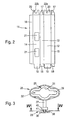
Figur 1 einen Verpackungsbehälter mit einem Aufhänger in schaubildlicher Ansicht, -
Figur 2 einen Packstoffzuschnitt des Verpackungsbehälters nachFigur 1 in Draufsicht, -
Figur 3 einen Aufhänger für den Verpackungsbehälter nach -
Figur 1 in Vorderansicht, -
Figur 4 einen Querschnitt durch den Aufhänger in der Ebene IV-IV derFigur 3 und -
Figuren 5 und 6 den Befestigungsvorgang eines modifizierten Aufhängers an dem Verpackungsbehälter in schaubildlicher Ansicht. - Der Verpackungsbehälter besteht aus einer Faltschachtel 10, die aus einem Zuschnitt 11 aus Pappe oder Karton hergestellt ist. Die Faltschachtel 10 hat die Form eines Quaders mit zwei schmalen Seitenwänden 12 und 13, einer Vorderwand 14 mit zwei Ausschnitten 21 zum Erkennen des Inhalts der Faltschachtel 10 und einer Rückwand 15. Eine Längslasche 16 verbindet die schmale Seitenwand 12 mit der Vorderwand 14. An den Querseiten der Seitenwände 12 und 13 sind schmale Faltlappen 17 und 18 und an der Vorderwand 14 und der Rückwand 15 breite Verschlusslappen 19 und 20 angeformt. Die schmalen Faltlappen 17 und 18 an den Seitenwänden 12 und 13 haben eine geringere Höhe als die Verschlusslappen 19 und 20 an der Vorder- 14 und Rückwand 15, deren Höhe der Breite der schmalen Seitenwände 12 und 13 entspricht. Die zwei gegenüberliegenden, einen Verschluss an einem Ende der Faltschachtel 10 bildenden Verschlusslappen 20 haben einen weitgehend V-förmig ausgebildeten Ausschnitt 22a bzw. einen weitgehend U-förmig ausgebildeten Ausschnitt 22b. Die Tiefe der Ausschnitte 22a und 22b an den Verschlusslappen 20 beträgt mindestens deren halbe Höhe, so dass beim Übereinanderfalten der beiden Verschlusslappen 20 ein Loch 23 entsteht.
- Ein mit der Faltschachtel 10 verbundener Aufhänger 25 (
Figur 3 ) hat eine Aufhängeöse 26 und einen über einen Steg 27 mit dieser verbundenen Anker 28. Die Aufhängeöse 26 hat einen Längsschlitz 29 und mittig in diesem bogenförmige Aussparungen 31, die zusammen eine Aufhängeöffnung 32 bilden. An die Aufhängeöse 26 schließt sich quer zu deren Längserstreckung der Steg 27 an. Am freien Ende des Stegs 27 hat der Anker 28 eine im Wesentlichen kreisförmige Platte 36. Oberhalb der Platte 36 ist über ein Zwischenstück 38 am Steg 27 ein Bund 40 angeordnet. Der Abstand zwischen dem Bund 40 und der Platte 36 entspricht mindestens der Dicke zweier Verschlusslappen 20, die bei mit der Faltschachtel 10 verbundenem Aufhänger 25 zwischen der Platte 36 und dem Bund 40 angeordnet sind. Weiterhin ist die Querschnittsfläche des Zwischenstücks 38 der Größe des Loches 23 bzw. den Ausschnitten 22a und 22b angepasst. - Entsprechend der
Figur 4 weist das Zwischenstück 38 eine im Wesentlichen U-förmige Querschnittsfläche 39 auf. Vom Umfang der Platte 36 geht eine Kerbe in Form eines V-förmigen Ausschnitts 42 aus, der über die offene Seite der U-förmigen Querschnittsfläche 39 bis in den Mittelbereich 43 der Platte 36 reicht. Der Öffnungswinkel α des Ausschnitts 42 beträgt etwa 20 Grad und der Durchmesser d der Platte 36 etwa 14 mm bis 16 mm. - Der Bund 40 hat auf der der Platte 36 zugewandten Seite eine Auflagefläche 41, so dass der Bund 40 bzw. dessen Auflagefläche 41 bei montiertem Aufhänger 25 als Eindrücksicherung für den Aufhänger 25 dient.
- Bei dem in den
Figuren 5 und 6 erkennbaren Aufhänger 25a ist erkennbar, dass das Zwischenstück 38a eine kreisförmige Querschnittsfläche aufweist, und dass der Ausschnitt 42a bis an das Zwischenstück 38a heranreicht. Weiterhin weist der Ausschnitt 42a einen größeren Öffnungswinkel, etwa 90 Grad, auf. - Mittels der Ausschnitte 42 bzw. 42a am Aufhänger 25 bzw. 25a lässt sich der Aufhänger 25, 25a in vorteilhafter Weise bei bereits verschlossener und befüllter Faltschachtel 10 an der Faltschachtel befestigen. Der Montagevorgang des Aufhängers 25 bzw. 25a ist anhand der
Figuren 5 und 6 dargestellt. Man erkennt, dass bei bereits verklebten Verschlusslappen 20 die Platte 36a des Aufhängers 25a mit seinem Ausschnitt 42a in das Loch 23 eingeführt wird (Figur 5 ). Anschließend wird der Aufhänger 25a im Ausführungsbeispiel im Uhrzeigersinn gedreht, wobei die Platte 36a nach und nach vollständig in das Loch 23 eintaucht. In derFigur 6 ist der Zustand dargestellt, in dem die Platte 36a sich vollständig unterhalb der beiden Verschlusslappen 20 befindet, wobei der Bund 40 bzw. die unterhalb der Verschlusslappen 20 befindlichen Verschlusslappen 17 ein weiteres Eintauchen des Aufhängers 25a in die Faltschachtel 10 verhindern.
Claims (7)
- Verpackungsbehälter mit einem Aufhänger (25; 25a), wobei der Verpackungsbehälter aus einer Faltschachtel (10) besteht, die mehrere Verschlusslappen (20) mit wenigstens einem Ausschnitt (22a, 22b) hat, wobei die übereinandergefalteten Verschlusslappen (20) einen Verschluß mit einem Loch (23) im Bereich des Ausschnitts (22a, 22b) ausbilden, in dem ein Anker (28) des Aufhängers (25; 25a) angeordnet ist, und wobei der Anker (28) an einem Ende eine Platte (36; 36a) hat, welche sich bei an der Faltschachtel (10) befestigtem Aufhänger (25; 25a) unterhalb der das Loch (23) ausbildenden Verschlusslappen (20) befindet, dadurch gekennzeichnet, dass in der Platte (36; 36a) ein Ausschnitt (42; 42a) in Form einer Kerbe ausgebildet ist, welche von der äußeren Umrandung der Platte (36; 36a) ausgeht, so dass die Platte (36; 36a), beginnend mit dem Ausschnitt (42; 42a) in das Loch (23) einführbar und anschließend vollständig in das Loch (23) der Faltschachtel (10) eindrehbar ist.
- Verpackungsbehälter nach Anspruch 1, dadurch gekennzeichnet, dass die Platte (36; 36a) eine kreisförmige Form aufweist.
- Verpackungsbehälter nach Anspruch 1 oder 2, dadurch gekennzeichnet, dass die Querschnittsfläche des Ankers (28) unmittelbar oberhalb der Platte (36) einen zumindest einseitig offenem, insbesondere U-förmigen Querschnitt (39) aufweist, dass die Querschnittsfläche den Mittelbereich (43) der Platte (36) freilässt und dass der Ausschnitt (42) von der offenen Seite der Querschnittsfläche bis in den Mittelbereich (43) der Platte (36) reicht.
- Verpackungsbehälter nach einem der Ansprüche 1 oder 2, dadurch gekennzeichnet, dass die Querschnittsfläche des Ankers (28) unmittelbar oberhalb der Platte (36a) kreisförmig ist und dass der Ausschnitt (42a) von der äußeren Umrandung der Platte (36a) bis an diese Querschnittsfläche heranreicht.
- Verpackungsbehälter nach einem der Ansprüche 1 bis 4, dadurch gekennzeichnet, dass der Ausschnitt (42; 42a) V-förmig ausgebildet ist.
- Verpackungsbehälter nach Anspruch 5, dadurch gekennzeichnet, dass der Öffnungswinkel des Ausschnitts (42; 42a) zwischen 20° und 90° beträgt.
- Verpackungsbehälter nach einem der Ansprüche 1 bis 6, dadurch gekennzeichnet, dass der Anker (28) beabstandet zur Platte (36; 36a) einen als Eindrücksicherung dienenden Bund (40) aufweist.
Applications Claiming Priority (2)
| Application Number | Priority Date | Filing Date | Title |
|---|---|---|---|
| DE102004031594A DE102004031594A1 (de) | 2004-06-30 | 2004-06-30 | Verpackungsbehälter mit einem Aufhänger |
| PCT/EP2005/052678 WO2006003072A1 (de) | 2004-06-30 | 2005-06-09 | Verpackungsbehälter mit einem aufhänger |
Publications (2)
| Publication Number | Publication Date |
|---|---|
| EP1763474A1 EP1763474A1 (de) | 2007-03-21 |
| EP1763474B1 true EP1763474B1 (de) | 2009-05-13 |
Family
ID=34972031
Family Applications (1)
| Application Number | Title | Priority Date | Filing Date |
|---|---|---|---|
| EP05762989A Expired - Lifetime EP1763474B1 (de) | 2004-06-30 | 2005-06-09 | Verpackungsbehälter mit einem aufhänger |
Country Status (6)
| Country | Link |
|---|---|
| EP (1) | EP1763474B1 (de) |
| CN (1) | CN100556764C (de) |
| AT (1) | ATE431295T1 (de) |
| DE (2) | DE102004031594A1 (de) |
| RU (1) | RU2373120C2 (de) |
| WO (1) | WO2006003072A1 (de) |
Family Cites Families (7)
| Publication number | Priority date | Publication date | Assignee | Title |
|---|---|---|---|---|
| DE7711963U1 (de) * | 1977-04-16 | 1977-08-18 | Tolges Kunststoffverarbeitung | Befestigungsvorrichtung fuer Haengeverpackungen zum Beispiel Bilderrahmenverpackung |
| SU1713853A1 (ru) * | 1989-02-13 | 1992-02-23 | Пензенский Филиал Научно-Исследовательского И Конструкторско-Технологического Института Местной Промышленности | Складна коробка |
| DE9421903U1 (de) * | 1993-03-12 | 1997-01-09 | Robert Bosch Gmbh, 70469 Stuttgart | Verpackungsbehälter mit einem Aufhänger |
| DE9303626U1 (de) * | 1993-03-12 | 1994-07-14 | Robert Bosch Gmbh, 70469 Stuttgart | Verpackungsbehälter mit einem Aufhänger |
| CN2451484Y (zh) * | 2000-09-29 | 2001-10-03 | 曹仲标 | 具灯笼功效的多用途容置盒 |
| CN2464647Y (zh) * | 2000-12-19 | 2001-12-12 | 中国第一铅笔股份有限公司 | 包装盒 |
| RU34926U1 (ru) * | 2003-08-26 | 2003-12-20 | Общество с ограниченной ответственностью "К-Системс" | Упаковка |
-
2004
- 2004-06-30 DE DE102004031594A patent/DE102004031594A1/de not_active Withdrawn
-
2005
- 2005-06-09 WO PCT/EP2005/052678 patent/WO2006003072A1/de not_active Ceased
- 2005-06-09 CN CNB2005800221145A patent/CN100556764C/zh not_active Expired - Fee Related
- 2005-06-09 EP EP05762989A patent/EP1763474B1/de not_active Expired - Lifetime
- 2005-06-09 RU RU2007103296/11A patent/RU2373120C2/ru not_active IP Right Cessation
- 2005-06-09 AT AT05762989T patent/ATE431295T1/de not_active IP Right Cessation
- 2005-06-09 DE DE502005007284T patent/DE502005007284D1/de not_active Expired - Lifetime
Also Published As
| Publication number | Publication date |
|---|---|
| CN101010240A (zh) | 2007-08-01 |
| DE502005007284D1 (de) | 2009-06-25 |
| EP1763474A1 (de) | 2007-03-21 |
| WO2006003072A1 (de) | 2006-01-12 |
| RU2007103296A (ru) | 2008-08-10 |
| DE102004031594A1 (de) | 2006-02-09 |
| ATE431295T1 (de) | 2009-05-15 |
| RU2373120C2 (ru) | 2009-11-20 |
| CN100556764C (zh) | 2009-11-04 |
Similar Documents
| Publication | Publication Date | Title |
|---|---|---|
| EP2125542B1 (de) | Verschliessvorrichtung aus kunststoff mit schneidhülse | |
| EP2354020B1 (de) | Schachtel, insbesondere Faltschachtel | |
| DE10239711A1 (de) | Wiederverschließbare, quaderförmige Faltschachtel mit Aufbrechsicherheitsverschluss und Aufhängelasche | |
| DE202014001622U1 (de) | Verpackung und Zuschnitt für eine Verpackung | |
| EP0265880A2 (de) | Faltschachtel | |
| WO1996025345A1 (de) | Verpackung für unterlegscheiben | |
| EP2900889B1 (de) | Kraftfahrzeug mit einer tür oder klappe mit einem schloss | |
| DE3340798A1 (de) | Verpackung in form einer schachtel aus karton | |
| DE102014211820A1 (de) | Stapelbarer Faltkarton | |
| EP1763474A1 (de) | Verpackungsbehälter mit einem aufhänger | |
| EP2724953B1 (de) | Transportverpackung mit stabilem Boden | |
| DE9316489U1 (de) | Kappenschachtel | |
| DE4339396C1 (de) | Tür- oder Fensterband | |
| DE8522799U1 (de) | Zuschnitt aus faltbarem Material wie Pappe, Wellpappe od. dgl. für einen Verpackungskarton mit Präsentationsfenster | |
| EP1507714A2 (de) | Ausguss-verschluss f r fl ssigkeitspackungen | |
| DE10355244A1 (de) | Wiederverschließbare, quaderförmige Faltschachtel mit seitlicher wiederverschließbarer Öffnung | |
| DE2832706A1 (de) | Deckel aus blech fuer behaelter mit im deckelspiegel vorgesehener aufreisslinie | |
| DE9314930U1 (de) | Verpackung zum Aufbewahren und gleichzeitigen Exponieren einer Flasche | |
| CH683832A5 (de) | Tragfaltschachtel. | |
| DE69907140T2 (de) | Faltschachtel mit schüttvorrichtung und verfahren zu ihrer herstellung | |
| DE202025102997U1 (de) | Haltevorrichtung für Solarmodule | |
| DE10324022A1 (de) | Befestigungssystem eines Kreuzkopfes auf der Kopfplatte einer Baustütze | |
| EP0381992B1 (de) | Faltschachtelzuschnitt und Schachtel hieraus | |
| DE2116343A1 (de) | Dosendeckel sowie Verfahren und Vorrichtung zu seiner Herstellung | |
| DE202004016649U1 (de) | Verschlusskappe für Behälter |
Legal Events
| Date | Code | Title | Description |
|---|---|---|---|
| PUAI | Public reference made under article 153(3) epc to a published international application that has entered the european phase |
Free format text: ORIGINAL CODE: 0009012 |
|
| 17P | Request for examination filed |
Effective date: 20070130 |
|
| AK | Designated contracting states |
Kind code of ref document: A1 Designated state(s): AT BE BG CH CY CZ DE DK EE ES FI FR GB GR HU IE IS IT LI LT LU MC NL PL PT RO SE SI SK TR |
|
| DAX | Request for extension of the european patent (deleted) | ||
| GRAP | Despatch of communication of intention to grant a patent |
Free format text: ORIGINAL CODE: EPIDOSNIGR1 |
|
| GRAS | Grant fee paid |
Free format text: ORIGINAL CODE: EPIDOSNIGR3 |
|
| GRAA | (expected) grant |
Free format text: ORIGINAL CODE: 0009210 |
|
| RIN1 | Information on inventor provided before grant (corrected) |
Inventor name: MUELLER, ASMUS |
|
| AK | Designated contracting states |
Kind code of ref document: B1 Designated state(s): AT BE BG CH CY CZ DE DK EE ES FI FR GB GR HU IE IS IT LI LT LU MC NL PL PT RO SE SI SK TR |
|
| REG | Reference to a national code |
Ref country code: GB Ref legal event code: FG4D Free format text: NOT ENGLISH |
|
| REG | Reference to a national code |
Ref country code: CH Ref legal event code: EP |
|
| REG | Reference to a national code |
Ref country code: IE Ref legal event code: FG4D |
|
| REF | Corresponds to: |
Ref document number: 502005007284 Country of ref document: DE Date of ref document: 20090625 Kind code of ref document: P |
|
| PG25 | Lapsed in a contracting state [announced via postgrant information from national office to epo] |
Ref country code: ES Free format text: LAPSE BECAUSE OF FAILURE TO SUBMIT A TRANSLATION OF THE DESCRIPTION OR TO PAY THE FEE WITHIN THE PRESCRIBED TIME-LIMIT Effective date: 20090824 Ref country code: PT Free format text: LAPSE BECAUSE OF FAILURE TO SUBMIT A TRANSLATION OF THE DESCRIPTION OR TO PAY THE FEE WITHIN THE PRESCRIBED TIME-LIMIT Effective date: 20090913 Ref country code: FI Free format text: LAPSE BECAUSE OF FAILURE TO SUBMIT A TRANSLATION OF THE DESCRIPTION OR TO PAY THE FEE WITHIN THE PRESCRIBED TIME-LIMIT Effective date: 20090513 Ref country code: LT Free format text: LAPSE BECAUSE OF FAILURE TO SUBMIT A TRANSLATION OF THE DESCRIPTION OR TO PAY THE FEE WITHIN THE PRESCRIBED TIME-LIMIT Effective date: 20090513 |
|
| NLV1 | Nl: lapsed or annulled due to failure to fulfill the requirements of art. 29p and 29m of the patents act | ||
| PG25 | Lapsed in a contracting state [announced via postgrant information from national office to epo] |
Ref country code: SI Free format text: LAPSE BECAUSE OF FAILURE TO SUBMIT A TRANSLATION OF THE DESCRIPTION OR TO PAY THE FEE WITHIN THE PRESCRIBED TIME-LIMIT Effective date: 20090513 Ref country code: SE Free format text: LAPSE BECAUSE OF FAILURE TO SUBMIT A TRANSLATION OF THE DESCRIPTION OR TO PAY THE FEE WITHIN THE PRESCRIBED TIME-LIMIT Effective date: 20090813 Ref country code: NL Free format text: LAPSE BECAUSE OF FAILURE TO SUBMIT A TRANSLATION OF THE DESCRIPTION OR TO PAY THE FEE WITHIN THE PRESCRIBED TIME-LIMIT Effective date: 20090513 Ref country code: PL Free format text: LAPSE BECAUSE OF FAILURE TO SUBMIT A TRANSLATION OF THE DESCRIPTION OR TO PAY THE FEE WITHIN THE PRESCRIBED TIME-LIMIT Effective date: 20090513 Ref country code: IS Free format text: LAPSE BECAUSE OF FAILURE TO SUBMIT A TRANSLATION OF THE DESCRIPTION OR TO PAY THE FEE WITHIN THE PRESCRIBED TIME-LIMIT Effective date: 20090913 |
|
| REG | Reference to a national code |
Ref country code: IE Ref legal event code: FD4D |
|
| BERE | Be: lapsed |
Owner name: ROBERT BOSCH G.M.B.H. Effective date: 20090630 |
|
| PG25 | Lapsed in a contracting state [announced via postgrant information from national office to epo] |
Ref country code: EE Free format text: LAPSE BECAUSE OF FAILURE TO SUBMIT A TRANSLATION OF THE DESCRIPTION OR TO PAY THE FEE WITHIN THE PRESCRIBED TIME-LIMIT Effective date: 20090513 Ref country code: DK Free format text: LAPSE BECAUSE OF FAILURE TO SUBMIT A TRANSLATION OF THE DESCRIPTION OR TO PAY THE FEE WITHIN THE PRESCRIBED TIME-LIMIT Effective date: 20090513 Ref country code: MC Free format text: LAPSE BECAUSE OF NON-PAYMENT OF DUE FEES Effective date: 20090630 Ref country code: IE Free format text: LAPSE BECAUSE OF FAILURE TO SUBMIT A TRANSLATION OF THE DESCRIPTION OR TO PAY THE FEE WITHIN THE PRESCRIBED TIME-LIMIT Effective date: 20090513 Ref country code: RO Free format text: LAPSE BECAUSE OF FAILURE TO SUBMIT A TRANSLATION OF THE DESCRIPTION OR TO PAY THE FEE WITHIN THE PRESCRIBED TIME-LIMIT Effective date: 20090513 Ref country code: CZ Free format text: LAPSE BECAUSE OF FAILURE TO SUBMIT A TRANSLATION OF THE DESCRIPTION OR TO PAY THE FEE WITHIN THE PRESCRIBED TIME-LIMIT Effective date: 20090513 |
|
| REG | Reference to a national code |
Ref country code: CH Ref legal event code: PL |
|
| PG25 | Lapsed in a contracting state [announced via postgrant information from national office to epo] |
Ref country code: SK Free format text: LAPSE BECAUSE OF FAILURE TO SUBMIT A TRANSLATION OF THE DESCRIPTION OR TO PAY THE FEE WITHIN THE PRESCRIBED TIME-LIMIT Effective date: 20090513 |
|
| PLBE | No opposition filed within time limit |
Free format text: ORIGINAL CODE: 0009261 |
|
| STAA | Information on the status of an ep patent application or granted ep patent |
Free format text: STATUS: NO OPPOSITION FILED WITHIN TIME LIMIT |
|
| PG25 | Lapsed in a contracting state [announced via postgrant information from national office to epo] |
Ref country code: BG Free format text: LAPSE BECAUSE OF FAILURE TO SUBMIT A TRANSLATION OF THE DESCRIPTION OR TO PAY THE FEE WITHIN THE PRESCRIBED TIME-LIMIT Effective date: 20090813 |
|
| 26N | No opposition filed |
Effective date: 20100216 |
|
| PG25 | Lapsed in a contracting state [announced via postgrant information from national office to epo] |
Ref country code: CH Free format text: LAPSE BECAUSE OF NON-PAYMENT OF DUE FEES Effective date: 20090630 Ref country code: LI Free format text: LAPSE BECAUSE OF NON-PAYMENT OF DUE FEES Effective date: 20090630 |
|
| PG25 | Lapsed in a contracting state [announced via postgrant information from national office to epo] |
Ref country code: BE Free format text: LAPSE BECAUSE OF NON-PAYMENT OF DUE FEES Effective date: 20090630 |
|
| PG25 | Lapsed in a contracting state [announced via postgrant information from national office to epo] |
Ref country code: AT Free format text: LAPSE BECAUSE OF NON-PAYMENT OF DUE FEES Effective date: 20090609 |
|
| PG25 | Lapsed in a contracting state [announced via postgrant information from national office to epo] |
Ref country code: GR Free format text: LAPSE BECAUSE OF FAILURE TO SUBMIT A TRANSLATION OF THE DESCRIPTION OR TO PAY THE FEE WITHIN THE PRESCRIBED TIME-LIMIT Effective date: 20090814 |
|
| PG25 | Lapsed in a contracting state [announced via postgrant information from national office to epo] |
Ref country code: LU Free format text: LAPSE BECAUSE OF NON-PAYMENT OF DUE FEES Effective date: 20090609 |
|
| PG25 | Lapsed in a contracting state [announced via postgrant information from national office to epo] |
Ref country code: HU Free format text: LAPSE BECAUSE OF FAILURE TO SUBMIT A TRANSLATION OF THE DESCRIPTION OR TO PAY THE FEE WITHIN THE PRESCRIBED TIME-LIMIT Effective date: 20091114 |
|
| PG25 | Lapsed in a contracting state [announced via postgrant information from national office to epo] |
Ref country code: TR Free format text: LAPSE BECAUSE OF FAILURE TO SUBMIT A TRANSLATION OF THE DESCRIPTION OR TO PAY THE FEE WITHIN THE PRESCRIBED TIME-LIMIT Effective date: 20090513 |
|
| PG25 | Lapsed in a contracting state [announced via postgrant information from national office to epo] |
Ref country code: CY Free format text: LAPSE BECAUSE OF FAILURE TO SUBMIT A TRANSLATION OF THE DESCRIPTION OR TO PAY THE FEE WITHIN THE PRESCRIBED TIME-LIMIT Effective date: 20090513 |
|
| REG | Reference to a national code |
Ref country code: FR Ref legal event code: PLFP Year of fee payment: 12 |
|
| REG | Reference to a national code |
Ref country code: FR Ref legal event code: PLFP Year of fee payment: 13 |
|
| REG | Reference to a national code |
Ref country code: FR Ref legal event code: PLFP Year of fee payment: 14 |
|
| PGFP | Annual fee paid to national office [announced via postgrant information from national office to epo] |
Ref country code: ES Payment date: 20180801 Year of fee payment: 14 |
|
| PGFP | Annual fee paid to national office [announced via postgrant information from national office to epo] |
Ref country code: IT Payment date: 20190619 Year of fee payment: 15 |
|
| PGFP | Annual fee paid to national office [announced via postgrant information from national office to epo] |
Ref country code: FR Payment date: 20190625 Year of fee payment: 15 |
|
| PGFP | Annual fee paid to national office [announced via postgrant information from national office to epo] |
Ref country code: GB Payment date: 20190624 Year of fee payment: 15 |
|
| REG | Reference to a national code |
Ref country code: DE Ref legal event code: R119 Ref document number: 502005007284 Country of ref document: DE |
|
| PG25 | Lapsed in a contracting state [announced via postgrant information from national office to epo] |
Ref country code: DE Free format text: LAPSE BECAUSE OF NON-PAYMENT OF DUE FEES Effective date: 20200101 |
|
| GBPC | Gb: european patent ceased through non-payment of renewal fee |
Effective date: 20200609 |
|
| PG25 | Lapsed in a contracting state [announced via postgrant information from national office to epo] |
Ref country code: GB Free format text: LAPSE BECAUSE OF NON-PAYMENT OF DUE FEES Effective date: 20200609 Ref country code: FR Free format text: LAPSE BECAUSE OF NON-PAYMENT OF DUE FEES Effective date: 20200630 |
|
| PG25 | Lapsed in a contracting state [announced via postgrant information from national office to epo] |
Ref country code: IT Free format text: LAPSE BECAUSE OF NON-PAYMENT OF DUE FEES Effective date: 20200609 |