EP1762909A2 - Bilderzeugungsvorrichtung - Google Patents
Bilderzeugungsvorrichtung Download PDFInfo
- Publication number
- EP1762909A2 EP1762909A2 EP06254674A EP06254674A EP1762909A2 EP 1762909 A2 EP1762909 A2 EP 1762909A2 EP 06254674 A EP06254674 A EP 06254674A EP 06254674 A EP06254674 A EP 06254674A EP 1762909 A2 EP1762909 A2 EP 1762909A2
- Authority
- EP
- European Patent Office
- Prior art keywords
- toner
- image
- light
- dark
- toner image
- Prior art date
- Legal status (The legal status is an assumption and is not a legal conclusion. Google has not performed a legal analysis and makes no representation as to the accuracy of the status listed.)
- Withdrawn
Links
Images



Classifications
-
- G—PHYSICS
- G03—PHOTOGRAPHY; CINEMATOGRAPHY; ANALOGOUS TECHNIQUES USING WAVES OTHER THAN OPTICAL WAVES; ELECTROGRAPHY; HOLOGRAPHY
- G03G—ELECTROGRAPHY; ELECTROPHOTOGRAPHY; MAGNETOGRAPHY
- G03G15/00—Apparatus for electrographic processes using a charge pattern
- G03G15/14—Apparatus for electrographic processes using a charge pattern for transferring a pattern to a second base
- G03G15/16—Apparatus for electrographic processes using a charge pattern for transferring a pattern to a second base of a toner pattern, e.g. a powder pattern, e.g. magnetic transfer
- G03G15/1605—Apparatus for electrographic processes using a charge pattern for transferring a pattern to a second base of a toner pattern, e.g. a powder pattern, e.g. magnetic transfer using at least one intermediate support
-
- G—PHYSICS
- G03—PHOTOGRAPHY; CINEMATOGRAPHY; ANALOGOUS TECHNIQUES USING WAVES OTHER THAN OPTICAL WAVES; ELECTROGRAPHY; HOLOGRAPHY
- G03G—ELECTROGRAPHY; ELECTROPHOTOGRAPHY; MAGNETOGRAPHY
- G03G2215/00—Apparatus for electrophotographic processes
- G03G2215/06—Developing structures, details
- G03G2215/0602—Developer
Definitions
- the present invention relates to an image-forming apparatus which primarily transfers a toner image from an image carrier onto an intermediate transfer body, and then secondarily transfers the toner image onto a recording medium, by using toners having the same hue and having different color densities, such as a dark magenta toner and a light magenta toner, or the like.
- an electrophotographic type image-forming apparatus has used toners having the same hue and having the different color densities, such as dark magenta toner and light magenta toner, or the like, for extending a color-reproduction range.
- a dark magenta toner image-forming unit and a light magenta toner image-forming unit are provided in this type of image-forming apparatus, so that a dark magenta toner image and a light magenta toner image are formed.
- the toner images formed on a photoconductor drum are primarily transferred onto the intermediate transfer body at a primary transfer region sequentially and electrostatically.
- the toner images of the respective colors which have been primarily transferred onto the intermediate transfer body are secondarily transferred onto a recording medium by a secondary transfer member with a bias applied.
- Remaining toner which is not primarily transferred onto the intermediate transfer body and remains at the photoconductor drum is collected by a cleaner provided at the photoconductor drum.
- secondary transfer remaining toner which is not transferred onto the recording medium and remains at the intermediate transfer body is collected by a cleaner provided at the intermediate transfer body.
- the toner images transferred onto the recording medium are conveyed to a fixer, and the toner images are heated and pressed on the recording medium to be fixed.
- the former toner image which has been primarily transferred can pass the primary transfer region and become charged when the other latter toner image is primarily transferred. Due to this, the amount of electric charge of the first primary toner image becomes greater than that of the subsequent primary toner image. Accordingly, there may be a difference between the amount of electric charge of the first transferred toner image and that of the second transferred toner image.
- the present invention provides an image-forming apparatus which uses toners having the same hue and having different densities so as to form toner images with desirable colors on a recording medium while the toner remaining after secondary transfer is decreased.
- the particle diameter of the formerly primarily transferred toner image is increased. Since toner having large particles is hard to charge, the amount of electric charge to be applied to the toner when passing the primary transfer region can be decreased. In addition, in order to prevent the image quality being impaired due to the usage of large-particle toner, the particle diameter of the light toner, of which image deterioration is less noticeable, is increased.
- the difference between the amounts of electric charge of the toner images can be decreased, and toner images having the desired colors can be formed on the recording medium.
- Fig. 1 is a schematic cross-sectional view showing an image-forming apparatus according to a first embodiment.
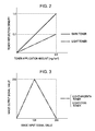
- Fig. 2 is an illustration showing the relationship between a dark toner and a light toner in terms of application amounts and optical densities of the toners.
- Fig. 3 is an illustration showing an image output signal with respect to an image input signal when a light magenta toner image and a light cyan toner image are formed.
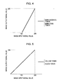
- Fig. 4 is an illustration showing an image output signal with respect to an image input signal when a dark magenta toner image and a dark cyan toner image are formed.
- Fig. 5 is an illustration showing an image output signal with respect to an image input signal when a yellow toner image and a black toner image are formed.
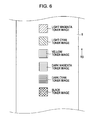
- Fig. 6 is an illustration schematically showing the toner images formed on an intermediate transfer belt when secondary transfer efficiency is measured.
- Fig. 7 is an illustration showing amounts of secondary transfer remaining toners with respect to secondary transfer biases when the volume mean particle diameter of a dark magenta toner and a light magenta toner is 5 ⁇ m.
- Fig. 8 is an illustration showing amounts of secondary transfer remaining toners with respect to secondary transfer biases when the volume mean particle diameter of the dark magenta toner is 5 ⁇ m, and that of the light magenta toner is 7 ⁇ m.
- Fig. 9 is a schematic cross-sectional view showing an image-forming apparatus according to a second embodiment.
- An image-forming apparatus is a full-color image-forming apparatus which primarily transfers a toner image formed on a photoconductor drum (image carrier) 1 onto an intermediate transfer belt (intermediate transfer body) 5, and then secondarily transfers the toner image onto a recording medium.
- the image-forming apparatus includes one photoconductor drum 1 and six developing devices (developer or toner image-forming devices) 4 which develop electrostatic images formed on the photoconductor drum 1.
- the six developing devices 4 are filled with toners of light cyan, light magenta, dark magenta, dark cyan, yellow and black, respectively.
- toner images of the light cyan, light magenta, dark magenta, dark cyan, yellow, and black, which are formed on the photoconductor drum 1 are primarily transferred onto the intermediate transfer belt 5 to be superimposed on each other. Then, the toner images are secondarily transferred onto the recording medium, collectively.
- Fig. 1 is a schematic cross-sectional view showing an image-forming apparatus 100 according to the present embodiment.
- the image-forming apparatus 100 includes a reader section A for reading an original document and a printer section B for forming an image based on image data.
- the original document is placed on an original-document glass plate (not shown), and is exposed to and scanned by an exposure lamp (not shown). Then, a reflected optical image of the original document is condensed at a full-color CCD sensor (not shown) by a lens (not shown) to acquire an image signal.
- the image signal is image processed by a video processing unit (not shown) via an amplifying circuit (not shown), and then sent to the printer section B.
- the printer section B forms an image on the basis of the image signal sent from the reader section A.
- the image-forming apparatus 100 can also form an image on the basis of an image signal sent from a computer or a facsimile in addition to the image signal sent from the reader section A.
- the image signal sent from the reader section A is converted into color signals which correspond to the colors of the light magenta, light cyan, yellow, dark magenta, dark cyan, and black, respectively, by a signal converter (not shown) provided at the printer section B.
- the color signals are stored in a storage unit (not shown).
- a laser optical system (exposure unit) 3 emits laser light L on the photoconductor drum 1 which rotates in a direction of an arrow R1 Fig. 1.
- the surface of the photoconductor drum 1 is evenly charged to have negative polarity by a primary charging device (primary transfer unit) 2 prior to the emitting of the laser light L.
- the surface of the photoconductor drum 1 is exposed to and destaticized by a pre-exposure lamp 11 before it is charged by the primary charging device 2.
- the six developing devices 4 are held by a rotary developing device holder 41.
- the rotary developing device holder 41 rotates in a direction of an arrow R2 in Fig. 1, the developing device 4 is moved to a position (development position D1) facing the photoconductor drum 1, so that the electrostatic image can be developed.
- the rotation of the rotary developing device holder 41 allows a light magenta developing device 41a, which is moved to the development position D1, to develop an electrostatic image of the light magenta, so that the toner image of the light magenta is formed on the photoconductor drum 1. At this time, the light magenta toner is charged to have negative polarity due to the developing device 4a.
- the light magenta toner image on the photoconductor drum 1 is transferred (primarily transferred) onto the intermediate transfer belt 5 by a primary transfer roller (primary transfer unit) 51 when the light magenta toner image reaches a primary transfer region T1 where the photoconductor drum 1 is in contact with the intermediate transfer belt 5.
- a primary transfer bias positive polarity which is opposite to the polarity of the toner is applied from a primary transfer bias supply (not shown) to the primary transfer roller 51.
- Light magenta toner which is not transferred onto the intermediate transfer belt 5 and remains at the photoconductor drum 1 is collected by a photoconductor drum cleaner 6.
- a toner image of the light cyan which is the second color, is formed in the same manner as that of the first-color toner image of the light magenta.
- a light cyan developing device 4b having light cyan toner is moved to the development position D1.
- the light cyan developing device 4b develops the electrostatic image, so that a light cyan toner image is formed on the photoconductor drum 1.
- the light cyan toner image is transferred by the primary transfer roller 51 so as to be superimposed on the light magenta toner image on the intermediate transfer belt 5 at the primary transfer region T1.
- the primary transfer bias (positive polarity) which is opposite to the polarity of the toner is applied to the primary transfer roller 51.
- a yellow toner image of the third color, a dark magenta toner image of the fourth color, a dark cyan toner image of the fifth color, and a black toner image of the sixth color are formed on the photoconductor drum 1. Then, the images are sequentially transferred to the intermediate transfer belt 5 so as to be superimposed on the intermediate transfer belt 5.
- the toner images of the above-mentioned six colors transferred onto the intermediate transfer belt 5 are collectively transferred onto a recording medium by a secondary transfer roller (secondary transfer unit) 52 at a secondary transfer region T2 where the secondary transfer roller 52 is in contact with the intermediate transfer belt 5.
- a secondary transfer bias is applied from a secondary transfer bias supply (not shown) to the secondary transfer roller 52.
- the secondary transfer bias (positive polarity) is opposite to the polarity of the toner.
- the recording medium is housed in a recording medium housing 7, and is supplied to the secondary transfer region T2 by a supplier 8.
- Remaining toner which is not transferred onto the recording medium during the secondary transfer process and which remains on the intermediate transfer belt 5 is collected by an intermediate transfer belt cleaner 57 which can move into contact with and away from the intermediate transfer belt 5.
- the recording medium on which the toner images are transferred is conveyed to a fixer 9 by a conveyor belt 82.
- the fixer 9 includes a pair of rollers which are biased towards one another, and a heater (not shown). When the recording medium with the toner image transferred passes the fixer 9, the recording medium is heated and pressed between the rollers, so that the toner images are fixed on the recording medium.
- the photoconductor drum 1 rotates in the direction of the arrow R1 in Fig. 1 by a driver (not shown).
- the photoconductor drum 1 has a conductive base layer, and a photoconductive layer is provided thereon.
- the photoconductor drum 1 may use an organic photosensitive member or an amorphous silicon photosensitive member. In this embodiment, the organic photosensitive member is used.
- the primary charging device 2 evenly charges the surface of the photoconductor drum 1 to have a predetermined polarity by applying a bias from a primary charge bias supply (not shown).
- the primary charging device 2 may be a corona charging device or a roller charging device.
- the primary charging device 2 employs a charging roller of contact charging type.
- the charging roller has an elastic layer made of urethane foam with carbon dispersed therein, on a metal core of the charging roller.
- the surface of the elastic layer is coated with fluorocarbon resin.
- the charging roller is pressed to the photoconductor drum 1 with a predetermined pressure applied by a presser (not shown), and is rotated along with the rotation of the photoconductor drum 1.
- a bias in which a direct voltage (-350 to -500 V) is superimposed on an alternating voltage (1000 Hz frequency and 1400 V amplitude) is applied to the charging roller by the primary charge bias supply.
- the application of the primary transfer bias, the primary charging device 2 evenly charges the photoconductor drum 1 to be approximately -500 V.
- the direct voltage of the bias to be applied is based on the measurement result of an electric potential sensor 12 which measures an electric potential of the charged surface of the photoconductor drum 1, and is controlled by a controller (not shown), so that the photoconductor drum 1 is charged to have a desirable electric potential.
- the laser optical system 3 is provided on the downstream of the primary charging device 2 in the rotation direction of the photoconductor drum 1.
- a light-emitting element 31 emits the laser light L.
- the laser light L is reflected by a rotatable polygon mirror 32, passes a lens 33, is reflected by reflection mirrors 34, and then impinges on the photoconductor drum 1.
- the laser light L impinges on the charged photoconductor drum 1
- an electrostatic image corresponding to the color signal is formed.
- the six developing devices 4 are provided, and are filled with the toners of light magenta, light cyan, yellow, dark magenta, dark cyan and black, respectively.
- the six developing devices 4 are held by the rotary developing device holder 41.
- the rotary developing device holder 41 rotates in the direction of the arrow R2
- the developing device 4 which develops the electrostatic image on the photoconductor drum 1 is moved to the development position D1.
- the developing device 4 of this embodiment uses a so-called two-component developing system.
- a toner and a carrier are mixed and the toner is friction charged by the carrier to have negative polarity.
- the developing device is filled with two-component developer in which the toner and the carrier are mixed.
- the toner contains coloring resin particles including biding resin, a coloring agent, and other additive if necessary; and coloring particles in which an external additive such as colloidal silica fine powder is externally added.
- the toner is negative-charged polyester resin.
- the toner is manufactured by polymerizing or grinding.
- the volume mean particle diameter of the manufactured toner is controlled to be uniform by selecting with a mesh, or by other method.
- the volume mean particle diameter may be 5 to 8 ⁇ m.
- the volume mean particle diameter of the toners of the light magenta and light cyan is 7 ⁇ m, while that of toners of the dark magenta, dark cyan, yellow and black is 5 ⁇ m. The method of measuring the volume mean particle diameter of the toners will be described later.
- the light cyan and the dark cyan have the same hue and have different reflection densities.
- the light magenta and the dark magenta have the above-stated correlation. The method of measuring the reflection density and the hue of the toner will be described later.
- the light cyan and light magenta are collectively referred to as a "light toner”, while the dark magenta, dark cyan, yellow and black are collectively referred to as a “dark toner”.
- the use of the light toner in addition to the dark toner may increase the color variations of the toner images to be formed.
- an amount of the coloring agent is controlled such that the reflection density of the toner becomes 1.4 when a mass per unit area (hereinafter, referred to as the "application amount") of the toner on a sheet of high-quality paper is 0.5 mg/cm 2 .
- an amount of the coloring agent is controlled such that the reflection density of the toner becomes 0.7 when the application amount of the toner on the sheet of the high-quality paper is 0.5 mg/cm 2 .
- Fig. 2 shows a comparison between the light toner and the dark toner in terms of the application amount on the sheet of the high-quality paper, and the reflection density. Both the light toner and the dark toner increase in the reflection density along with the increase in the application amount.
- the application amount is 0.5 mg/cm 2
- the reflection amount of the light toner is 0.7
- that of the dark toner is 1.4.
- the carrier may use surface oxidized or unoxidized metal, such as iron, nickel, cobalt, manganese, chrome, or rear earth, or an alloy of these, oxide ferrite, or the like.
- the method of manufacturing the carrier may be polymerizing.
- the volume mean particle diameter of the carrier may be 20 to 50 ⁇ m, and more particularly, the diameter may be 30 to 40 ⁇ m, while the resistivity thereof may be 10 7 ⁇ cm or higher, and more particularly, the resistivity may be 10 8 ⁇ cm or higher.
- toner housings lOa to 10f which house the toners of the respective colors are provided. If the toners in the developing devices 4a to 4f are used, the toners are supplied from the toner housings 10a to 10f as necessary.
- a toner image formed on the photoconductor drum under a given condition is transferred onto the intermediate transfer belt 5, and then is detected by a detection sensor 56.
- the amounts of the toners to be supplied to the developing devices 4a to 4f are controlled, so that the weight ratio (TD ratio) of the toner and the carrier in each of the developing devices 4a to 4f is kept to fall in a predetermined value.
- the TD ratio is represented by T/(T + D) where T(g) is a weight of the toner in the developing device 4 and D(g) is a weight of the carrier. In this embodiment, the TD ratio is kept to be approximately 8% in each of the developing devices 4a to 4f.
- the signal converter converts an image signal (image input signal) sent from the reader section A into a signal (image output signal) to be sent to the laser optical system 3 to form an electrostatic image.
- the relationship between the image input signal and the image output signal is different corresponding to the color of the toner image to be formed.
- Fig. 3 is an illustration showing the relationship between an image output signal value and an image input signal value with respect to the light magenta toner and the light cyan toner.
- a line shown in Fig. 3 represents both the light magenta toner and the light cyan toner.
- Fig. 4 is an illustration showing the relationship between an image output signal value and an image input signal value with respect to the dark magenta toner and the dark cyan toner.
- a line shown in Fig. 4 represents both the dark magenta toner and the dark cyan toner.
- Fig. 5 is an illustration showing the relationship between an image output signal value and an image input signal value with respect to the yellow toner and the black toner.
- a line shown in Fig. 5 represents both the yellow toner and the black toner.
- the intermediate transfer belt 5 is an endless belt, and is supported by a driving roller 55, a plurality of driven rollers 53, and a secondary transfer inner roller 54.
- the driving roller 55 is rotated by the driver (not shown), the intermediate transfer belt 5 rotates in a direction of an arrow R3 in Fig. 1.
- the material of the intermediate transfer belt 5 may be resin such as polyimide or polycarbonate. In this embodiment, polyimide is used.
- the thickness of the intermediate transfer belt 5 may be approximately 0.1 to 2 mm. In this embodiment, the thickness is 0.2 mm.
- the resistance of the intermediate transfer belt 5 is controlled to a desirable value by using a resistance regulating agent such as carbon.
- the resistance may be 1 ⁇ 10 6 to 1 ⁇ 10 13 ⁇ cm in terms of volume resistivity.
- the volume resistivity is 1 ⁇ 10 8 ⁇ cm.
- the primary transfer roller 51 is positioned at the primary transfer region T1 to face the photoconductor drum 1 with the intermediate transfer belt 5 interposed therebetween.
- the primary transfer roller 51 is rotatably supported by a supporting member (not shown).
- the primary transfer roller 51 may be a member provided with an elastic layer on a core metal thereof.
- the elastic layer uses polyurethane formed rubber.
- the hardness (Asker C) of the elastic layer is 10.
- the resistance regulating agent is dispersed in the elastic layer, and the volume resistivity thereof is controlled to approximately 1 ⁇ 10 6 ⁇ cm.
- the primary transfer bias supply (not shown) applies the bias (positive polarity) which is opposite to the polarity of the toner image
- the toner image on the photoconductor drum 1 is transferred onto the intermediate transfer belt 5.
- the direct voltage of +500 to +750 V is applied to the primary transfer roller 51.
- the secondary transfer roller 52 is positioned at the secondary transfer region T2 to face the secondary transfer inner roller 54 with the intermediate transfer belt 5 interposed therebetween.
- the secondary transfer roller 52 is rotatably supported by a supporting member (not shown).
- the secondary transfer roller 52 may be a member provided with an elastic layer on a core metal thereof.
- the elastic layer uses polyurethane formed rubber.
- the hardness (Asker C) of the elastic layer is 10.
- the resistance regulating agent is dispersed in the elastic layer, and the volume resistivity thereof is controlled to approximately 1 ⁇ 10 7 ⁇ cm.
- the secondary transfer bias supply (not shown) applies the bias (positive polarity) which is opposite to the polarity of the toner image
- the toner image on the intermediate transfer belt 5 is transferred onto the recording medium.
- +1 to +3 kV is applied to the secondary transfer roller 52.
- the intermediate transfer belt cleaner 57 is provided so as to move into contact with and away from the intermediate transfer belt 5. That is, while the toner image on the photoconductor drum 1 is primarily transferred onto the intermediate transfer belt 5, the intermediate transfer belt cleaner 57 is away from the intermediate transfer belt 5. When the primary transfer is completed, the intermediate transfer belt cleaner 57 comes into contact with the intermediate transfer belt 5.
- the intermediate transfer belt cleaner 57 uses a polyurethane blade member with the durometer A hardness being 75 and the thickness being 2 mm.
- the rollers for the fixer 9 are made of metal and are covered with a fluorocarbon rubber such as PTFA on the surface(which has mold release properties).
- this embodiment uses the six-color toners.
- the volume particle diameter of the toners of the first-color light magenta and the second-color light cyan is 7 ⁇ m, while that of the third-color dark magenta, the fourth-color dark cyan, the fifth-color yellow, and the sixth-color black is 5 ⁇ m.
- particle-diameter combination 1 represents the secondary transfer efficiency of each toner image of the first to sixth colors when the volume mean particle diameter of the toners of the first and second colors is 7 ⁇ m, while that of the third to sixth colors is 5 ⁇ m.
- particle-diameter combination 2 represents the secondary transfer efficiency when the volume mean particle diameter of each toner of the first to sixth colors is 5 ⁇ m.
- the secondary transfer efficiency is measured by forming each toner image of the respective colors on the intermediate transfer belt 5 in a line along the advancing direction of the intermediate transfer belt 5. Then, the mass per unit area of each toner image on the intermediate transfer belt 5 is compared with that on the recording medium after the secondary transfer.
- the secondary transfer efficiency in Table 1 is expressed by the following expression.
- secondary transfer efficiency mass of toner image per unit area on recording medium / ( mass of toner image per unit area on intermediate transfer belt ) ] ⁇ 100
- Table 1 Order of Color First Color Second Color Third Color Fourth Color Fifth Color Sixth Color Particle-Diameter Combination 1 90.0% 91.0% 90.3% 91.8% 93.2% 95.2%
- Particle-Diameter Combination 2 88.0% 89.0% 90.2% 91.5% 93.1% 95.0%
- Table 2 shows an amount of electric charge per unit area of each toner image of the respective colors on the photoconductor drum 1, according to the "particle-diameter combination 2".
- the toner image on the intermediate transfer belt 5 is charged with the primary transfer bias which is applied to the primary transfer roller 51 each time when passing the primary transfer region T1. Accordingly, the toner image which is first transferred passes the primary transfer region T1 for larger number of times. In addition, the toner image which is first primarily transferred receives higher electric charge in the secondary transfer.
- Fig. 7 represents the relationship between the voltage of the secondary transfer bias and the amount of the secondary transfer remaining toner, according to the "particle-diameter combination 2".
- Fig. 7 shows the relationship between the first-color light magenta toner image and the fourth-color dark magenta toner image.
- Table 3 shows an amount of electric charge per unit area of each toner image of the respective colors on the photoconductor drum 1, according to the "particle-diameter combination 1".
- the amounts of electric charge of the toner images of the first and second colors are decreased relative to that of the third to sixth colors. This is possibly because the contact area of the toner and the carrier is decreased if the particle diameter of the toner is increased, so that the amount of electric charge applied due to the contact charging with the carrier is decreased.
- this is possibly because the area to be charged at the primary transfer region T1 is decreased if the particle diameter of the toner is increased, so that the amount of electric charge applied to the toner per unit weight when passing the primary transfer region T1 is decreased.
- the amounts of electric charge of the toner images of the first and second colors are decreased relative to that of the third to sixth colors.
- the number of times each toner image of the first and second colors passes the primary transfer region T1 are grater than the number of times each toner image of the third to sixth colors passes the primary transfer region T1. Accordingly, when the sixth-color toner image has been primarily transferred, and the secondary transfer is performed, the differences of the amounts of electric charge among the six-color toners become small. This is possibly because the difference between the secondary transfer bias which allows the amount of the secondary transfer remaining toner of the first-color light magenta toner to be the least; and that of the sixth-color black toner to become small.
- the secondary transfer remaining toner of the dark magenta toner image and that of the light magenta toner image can be decreased together, thereby realizing good secondary transfer efficiency.
- the volume mean particle diameter of the toner for forming the toner image which is formerly primarily transferred is set larger than that of the toner for forming the toner image which is latterly primarily transferred, thereby attaining the good secondary transfer efficiency. Accordingly, the toner images of the desirable colors can be formed on the recording medium.
- E-SPART MODEL EST-II manufactured by Hosokawa Micron Corporation was used.
- the measurement condition included that Field Voltage is 100 (V) and Particle Density is 1 (g/cm 3 ), and the mean amount of electric charge per unit mass was assumed as the amount of electric charge per unit mass of the toner of the toner image.
- volume mean particle diameter of the toner employed according to the present invention was measured as follows.
- the measurement was carried out within a range between 0.4 to 60 ⁇ m, by using laser scan type particle size distribution measuring apparatus (CIS-100, manufactured by GALAI Co., Ltd.) for the toner having the volume mean particle diameter of 3 ⁇ m or more.
- the sample for the measurement was prepared as follows. First, 0.2 ml of a surfactant (alkylbenzene sulphonate) is added to 100 ml of water and 0.5 to 2 mg of the toner for the measurement was added thereto. Then, this was dispersed by ultrasonic disperser for 2 minutes, then 1 or 2 drops of the resulting sample were added to a cubic cell filled with water to nearly 80% containing a magnet stirrer.
- a surfactant alkylbenzene sulphonate
- the reflection density and the hue of the toner were measured as follows.
- the toner images of the respective colors as shown in Fig. 6 are formed on the intermediate transfer belt 5, and then are secondarily transferred on a sheet of CLC paper (80 g/m 2 ) manufactured by CANON HANBAI KABUSHIKI KAISHA.
- the secondary transfer allows the toner image with a predetermined application amount to be formed on a sheet of CLC paper (80 g/m 2 ).
- the toner images are fixed on the sheet of CLC paper (80 g/m 2 ) by using the fixer of the image-forming apparatus.
- the fixing condition employs one used for usually forming an image by using the sheet of CLC paper (80 g/m 2 ).
- each toner image formed on the sheet of CLC paper (80 g/m 2 ) is measured with X-Rite 504 manufactured by X-Rite, Inc. (optical system condition: incident angle is 45° and light-receiving angle is 0°, and filter condition: status A). Accordingly, the density and the hue of the toner can be obtained.
- the application amount of each toner image formed on the sheet of CLC paper 80 g/m 2
- the application amount of each toner image formed on the sheet of CLC paper 80 g/m 2
- the optical density and the hue of each toner is measured.
- Fig. 9 is a second embodiment of the present invention.
- the image-forming apparatus according to the present embodiment employs tandem system where image-forming units Pa to Pf each of which is provided with the photoconductor drum 1 are disposed along the intermediate transfer belt 5 which rotates in the direction of the arrow R2.
- volume mean particle diameter, density and hue of each toner are equivalent to that of the first embodiment, and the measurement of the amount of electric charge per unit mass ot each toner employs the same method as that of the first embodiment.
- toner images of the light magenta, light cyan, yellow, dark magenta, dark cyan and black are formed at Pa, Pb, Pc, Pd, Pe, Pf. Then the formed toner images are transferred (primarily transferred) onto the intermediate transfer belt 5 in a superimposed manner. The toner images are collectively transferred (secondarily transferred) onto the recording medium.
- a light magenta toner image-forming unit Pa and a light cyan toner image-forming unit Pb are disposed sequentially from the upstream in the rotation direction of the intermediate transfer belt 5 toward the downstream.
- a yellow toner image-forming unit Pc, a dark magenta toner image-forming unit Pd, a dark cyan toner image-forming unit Pe, and a black toner image-forming unit Pf are disposed. Note that these toners have similar configurations except that the colors of the toner images to be formed are different.
- the image-forming units Pa, Pb, Pc, Pd, Pe, Pf include processing units disposed around rotatable photoconductor drums 1a, 1b, 1c, 1d, 1e, 1f, respectively. Particularly, primary charging devices 2a, 2b, 2c, 2d, 2e, 2f, and developing devices 4a, 4b, 4c, 4d, 4e, 4f are so disposed. In addition, photoconductor drum cleaners 6a, 6b, 6c, 6d, 6e, 6f, and pre-exposure lamps 11a, 11b, 11c, 11d, 11e, 11f are provided. Further, primary transfer rollers 51a, 51b, 51c, 51d, 51e, 51f are provided at positions where the photoconductor drums 1 each are in contact with the intermediate transfer belt 5.
- the rotatable photoconductor drum 1 is discharged by the pre-exposure lamp 11a, and then evenly charged to have negative polarity by the primary charging device 2a.
- the laser optical system 3a emits laser light La corresponding to the color signal to impinge on the charged photoconductor drum 1a, thereby forming an electrostatic image.
- the developing device 4a of the two-component system develops the electrostatic image by using the light magenta toner to form a light magenta toner image.
- the rotation of the photoconductor drum 1a allows the light magenta toner image on the photoconductor drum 1a to reach a primary transfer region T1a where the intermediate transfer belt 5 is in contact with the photoconductor drum 1a.
- a bias (positive polarity) opposite to the polarity of the light magenta toner is applied to the primary transfer roller 5a at the primary transfer region T1a, the light magenta toner image is primarily transferred onto the intermediate transfer belt 5. Further, the toner remaining at the photoconductor drum 1a is removed by the photoconductor drum cleaner 6a.
- toner images are formed on other image-forming units Pb, Pc, Pd, Pe, Pf, respectively. Also, the toner images are primarily transferred onto the intermediate transfer belt 5 which moves in the direction of the arrow R2.
- the recording medium housed in the recording medium housing 7 which is provided at a lower portion of the printer section B is supplied to the secondary transfer region T2 by the supplier 8, synchronously with the image formation.
- the toner images on the intermediate transfer belt 5 are transferred onto the supplied recording medium. Further, the recording medium is conveyed to the fixer 9, so that the toner images are fixed on the recording medium by the fixer 9.
- the toner which is not transferred onto the recording medium and remains at the intermediate transfer belt 5 is collected by the intermediate transfer belt cleaner 57.
- the same toners as that of the first embodiment are used.
- the volume mean particle diameter of the first-color light magenta toner and the second-color light cyan toner is 7 ⁇ m.
- the volume mean particle diameter of the third-color yellow toner, fourth-color dark magenta toner, fifth-color dark cyan toner and sixth-color black toner is 5 ⁇ m.
- the amount of electric charge per unit area of the toner image of the toner on the photoconductor drum 1 of each image-forming unit exhibits the following results, which is the same as the result of the first embodiment.
- the toner image formerly primarily transferred on the intermediate transfer belt 5 is charged when passing other primary transfer regions located downstream in the rotation direction of the intermediate transfer belt 5.
- the amount of electric charge of the toner image which is first primarily transferred on the photoconductor drum 1 is decreased relative to that of the toner image which is latterly primarily transferred, by taking into account the charge applied to the former toner image when passing the primary transfer region T1 located on the downstream.
- the particle diameter of the toner of the toner image which is first primarily transferred is larger than that of the toner image which is latterly primarily transferred. This decreases the amount of electric charge applied when the toner image, which is formerly transferred, passes the primary transfer region T1, and enables good secondary transfer.
- toner images with the desired colors can be formed on the recording medium.
Landscapes
- Physics & Mathematics (AREA)
- General Physics & Mathematics (AREA)
- Developing Agents For Electrophotography (AREA)
- Color Electrophotography (AREA)
- Electrostatic Charge, Transfer And Separation In Electrography (AREA)
Applications Claiming Priority (1)
| Application Number | Priority Date | Filing Date | Title |
|---|---|---|---|
| JP2005265526 | 2005-09-13 |
Publications (2)
| Publication Number | Publication Date |
|---|---|
| EP1762909A2 true EP1762909A2 (de) | 2007-03-14 |
| EP1762909A3 EP1762909A3 (de) | 2009-11-25 |
Family
ID=37530619
Family Applications (1)
| Application Number | Title | Priority Date | Filing Date |
|---|---|---|---|
| EP06254674A Withdrawn EP1762909A3 (de) | 2005-09-13 | 2006-09-07 | Bilderzeugungsvorrichtung |
Country Status (3)
| Country | Link |
|---|---|
| US (1) | US20070059056A1 (de) |
| EP (1) | EP1762909A3 (de) |
| CN (1) | CN100524080C (de) |
Families Citing this family (2)
| Publication number | Priority date | Publication date | Assignee | Title |
|---|---|---|---|---|
| JP4708922B2 (ja) * | 2005-08-31 | 2011-06-22 | キヤノン株式会社 | 画像形成装置 |
| JP5496022B2 (ja) * | 2010-08-27 | 2014-05-21 | キヤノン株式会社 | 画像形成装置 |
Family Cites Families (7)
| Publication number | Priority date | Publication date | Assignee | Title |
|---|---|---|---|---|
| US6498910B2 (en) * | 2000-04-07 | 2002-12-24 | Konica Corporation | Image forming with light and dark hue toners |
| JP2002072572A (ja) * | 2000-08-30 | 2002-03-12 | Konica Corp | 画像形成装置及びカラー画像形成装置 |
| JP2002236396A (ja) * | 2001-02-08 | 2002-08-23 | Konica Corp | 画像形成装置と画像形成方法 |
| US6819902B2 (en) * | 2002-03-29 | 2004-11-16 | Canon Kabushiki Kaisha | Image forming apparatus with interchangeable developing devices |
| KR100538497B1 (ko) * | 2002-05-20 | 2005-12-23 | 캐논 가부시끼가이샤 | 토너 키트, 토너 및 화상 형성 방법 |
| JP2004029057A (ja) * | 2002-06-21 | 2004-01-29 | Canon Inc | 画像形成装置 |
| KR100564958B1 (ko) * | 2002-09-12 | 2006-03-30 | 가부시키가이샤 리코 | 컬러 화상 형성 장치 |
-
2006
- 2006-08-31 US US11/469,249 patent/US20070059056A1/en not_active Abandoned
- 2006-09-07 EP EP06254674A patent/EP1762909A3/de not_active Withdrawn
- 2006-09-13 CN CNB2006101518244A patent/CN100524080C/zh not_active Expired - Fee Related
Also Published As
| Publication number | Publication date |
|---|---|
| EP1762909A3 (de) | 2009-11-25 |
| CN100524080C (zh) | 2009-08-05 |
| US20070059056A1 (en) | 2007-03-15 |
| CN1932681A (zh) | 2007-03-21 |
Similar Documents
| Publication | Publication Date | Title |
|---|---|---|
| US7729650B2 (en) | Image forming apparatus | |
| KR0171167B1 (ko) | 화상 형성 장치 | |
| US7321741B2 (en) | Image forming apparatus featuring a transparent image forming station to achieve uniform gloss | |
| US8326195B2 (en) | Transfer device and image forming apparatus | |
| KR100198170B1 (ko) | 화상 형성 장치 | |
| CN101510066B (zh) | 转印装置及成像设备 | |
| JP2002207334A (ja) | 画像形成装置 | |
| CN100394318C (zh) | 图像形成装置 | |
| JP2002072613A (ja) | 画像形成装置 | |
| EP0706097B1 (de) | Bilderzeugungsverfahren | |
| EP1762909A2 (de) | Bilderzeugungsvorrichtung | |
| JP2002341606A (ja) | 画像形成装置 | |
| US6097920A (en) | Recording apparatus and method including intermediate transfer medium | |
| JP4926845B2 (ja) | 画像形成装置 | |
| US6519422B1 (en) | Image forming apparatus featuring a temperature-sensitive apparatus identifying feature | |
| JP2004029514A (ja) | 画像形成装置 | |
| AU2014200724B2 (en) | Image forming apparatus, and image forming method | |
| JP2002174910A (ja) | カラー用画像形成装置 | |
| JP4627251B2 (ja) | 画像形成装置 | |
| JP3337731B2 (ja) | 画像形成装置 | |
| JP4212267B2 (ja) | 所望のカラー印刷ができる電子写真現像装置 | |
| JP2005077842A (ja) | 画像形成装置 | |
| JP2010181666A (ja) | カラー画像形成装置 | |
| JP2007108692A (ja) | 画像形成装置 | |
| JP2002214870A (ja) | 画像形成装置 |
Legal Events
| Date | Code | Title | Description |
|---|---|---|---|
| PUAI | Public reference made under article 153(3) epc to a published international application that has entered the european phase |
Free format text: ORIGINAL CODE: 0009012 |
|
| AK | Designated contracting states |
Kind code of ref document: A2 Designated state(s): AT BE BG CH CY CZ DE DK EE ES FI FR GB GR HU IE IS IT LI LT LU LV MC NL PL PT RO SE SI SK TR |
|
| AX | Request for extension of the european patent |
Extension state: AL BA HR MK YU |
|
| PUAL | Search report despatched |
Free format text: ORIGINAL CODE: 0009013 |
|
| AK | Designated contracting states |
Kind code of ref document: A3 Designated state(s): AT BE BG CH CY CZ DE DK EE ES FI FR GB GR HU IE IS IT LI LT LU LV MC NL PL PT RO SE SI SK TR |
|
| AX | Request for extension of the european patent |
Extension state: AL BA HR MK RS |
|
| 17P | Request for examination filed |
Effective date: 20100525 |
|
| 17Q | First examination report despatched |
Effective date: 20100622 |
|
| AKX | Designation fees paid |
Designated state(s): AT BE BG CH CY CZ DE DK EE ES FI FR GB GR HU IE IS IT LI LT LU LV MC NL PL PT RO SE SI SK TR |
|
| STAA | Information on the status of an ep patent application or granted ep patent |
Free format text: STATUS: THE APPLICATION HAS BEEN WITHDRAWN |
|
| 18W | Application withdrawn |
Effective date: 20100910 |