EP1759898A1 - Vorrichtung zur Belüftung eines Fahrzeugs - Google Patents
Vorrichtung zur Belüftung eines Fahrzeugs Download PDFInfo
- Publication number
- EP1759898A1 EP1759898A1 EP06015333A EP06015333A EP1759898A1 EP 1759898 A1 EP1759898 A1 EP 1759898A1 EP 06015333 A EP06015333 A EP 06015333A EP 06015333 A EP06015333 A EP 06015333A EP 1759898 A1 EP1759898 A1 EP 1759898A1
- Authority
- EP
- European Patent Office
- Prior art keywords
- actuator
- frequency
- actuators
- control
- control signal
- Prior art date
- Legal status (The legal status is an assumption and is not a legal conclusion. Google has not performed a legal analysis and makes no representation as to the accuracy of the status listed.)
- Granted
Links
Images
Classifications
-
- B—PERFORMING OPERATIONS; TRANSPORTING
- B60—VEHICLES IN GENERAL
- B60H—ARRANGEMENTS OF HEATING, COOLING, VENTILATING OR OTHER AIR-TREATING DEVICES SPECIALLY ADAPTED FOR PASSENGER OR GOODS SPACES OF VEHICLES
- B60H1/00—Heating, cooling or ventilating devices
- B60H1/00421—Driving arrangements for parts of a vehicle air-conditioning
- B60H1/00428—Driving arrangements for parts of a vehicle air-conditioning electric
-
- B—PERFORMING OPERATIONS; TRANSPORTING
- B60—VEHICLES IN GENERAL
- B60H—ARRANGEMENTS OF HEATING, COOLING, VENTILATING OR OTHER AIR-TREATING DEVICES SPECIALLY ADAPTED FOR PASSENGER OR GOODS SPACES OF VEHICLES
- B60H1/00—Heating, cooling or ventilating devices
- B60H1/00642—Control systems or circuits; Control members or indication devices for heating, cooling or ventilating devices
- B60H1/00664—Construction or arrangement of damper doors
- B60H1/00671—Damper doors moved by rotation; Grilles
-
- B—PERFORMING OPERATIONS; TRANSPORTING
- B60—VEHICLES IN GENERAL
- B60H—ARRANGEMENTS OF HEATING, COOLING, VENTILATING OR OTHER AIR-TREATING DEVICES SPECIALLY ADAPTED FOR PASSENGER OR GOODS SPACES OF VEHICLES
- B60H1/00—Heating, cooling or ventilating devices
- B60H1/00642—Control systems or circuits; Control members or indication devices for heating, cooling or ventilating devices
- B60H1/00814—Control systems or circuits characterised by their output, for controlling particular components of the heating, cooling or ventilating installation
- B60H1/00821—Control systems or circuits characterised by their output, for controlling particular components of the heating, cooling or ventilating installation the components being ventilating, air admitting or air distributing devices
- B60H1/00835—Damper doors, e.g. position control
- B60H1/00857—Damper doors, e.g. position control characterised by the means connecting the initiating means, e.g. control lever, to the damper door
-
- B—PERFORMING OPERATIONS; TRANSPORTING
- B60—VEHICLES IN GENERAL
- B60H—ARRANGEMENTS OF HEATING, COOLING, VENTILATING OR OTHER AIR-TREATING DEVICES SPECIALLY ADAPTED FOR PASSENGER OR GOODS SPACES OF VEHICLES
- B60H1/00—Heating, cooling or ventilating devices
- B60H1/34—Nozzles; Air-diffusers
- B60H2001/3471—Details of actuators
-
- Y—GENERAL TAGGING OF NEW TECHNOLOGICAL DEVELOPMENTS; GENERAL TAGGING OF CROSS-SECTIONAL TECHNOLOGIES SPANNING OVER SEVERAL SECTIONS OF THE IPC; TECHNICAL SUBJECTS COVERED BY FORMER USPC CROSS-REFERENCE ART COLLECTIONS [XRACs] AND DIGESTS
- Y02—TECHNOLOGIES OR APPLICATIONS FOR MITIGATION OR ADAPTATION AGAINST CLIMATE CHANGE
- Y02T—CLIMATE CHANGE MITIGATION TECHNOLOGIES RELATED TO TRANSPORTATION
- Y02T10/00—Road transport of goods or passengers
- Y02T10/80—Technologies aiming to reduce greenhouse gasses emissions common to all road transportation technologies
- Y02T10/88—Optimized components or subsystems, e.g. lighting, actively controlled glasses
Definitions
- the invention relates to a device for ventilating a vehicle according to the preamble of claim 1 and a use of this device.
- WO 20051016673 A1 describes various air vents for motor vehicles, in which it can be provided that a metering device or a flap of a first air duct and a second metering device or flap of a second air duct are opened and closed alternately by means of a control device, wherein the mutual opening and closing can be made oscillating and the oscillation frequency is adjustable.
- adjustment of an air vent may be via stepper motors, which include control electronics located mostly on the engine.
- a setpoint number of steps is transmitted to the actuator by means of a data bus system via a central main control unit. After the stepping motor has been moved by the desired number of steps, if necessary, an actual step number is returned to the main control unit for checking purposes.
- the step frequency of the motors is fixed.
- At least one of the actuators comprises a stepping motor, wherein a number of pulses of the control signal corresponds to a number of setting steps of the stepping motor.
- the control electronics of the actuator or stepping motor is connected via a signal bus to a main control unit, wherein a desired frequency or target step frequency of the control signal from the main control unit to the control electronics is transferable and wherein the control signal for the motor is generated by the control electronics.
- a change of an air flow of a first discharge nozzle from a directional adjustment causes a diffuse adjustment.
- a directional control unit of a discharge nozzle is adjustable in its direction (waving operation). It is also possible for any combination of two or more actuators to be controlled in synchronism with one another, so that any combined movement sequence of directional or spot-diffuse transitions can be achieved. This also applies to the case of different rotational angles of the individual actuators.
- an oscillating or periodic adjusting movement of the actuator can be set by means of a specification of the step frequency.
- the first actuator as well as the second actuator perform an oscillating adjusting movement, synchronization of the one actuator to the other actuator being achieved by setting the frequency, in particular of two different step frequencies assigned to the respective actuators.
- an oscillating conversion of two different discharge nozzles between a spot mode and a diffuse mode can be carried out reliably and simply.
- a device according to the invention can advantageously be used in places where previously, by means of mostly complicated kinematic connections or control means, different, mutually correlated flaps be adjusted.
- This can be the setting of the air distribution of a vehicle air conditioning system, for example for the regulation of defrosting, footwell and ventilation flaps via a common servomotor and a flap connecting the optionally adjustable kinematics.
- a device according to the invention By means of the device according to the invention, such contiguous movements can be simulated in a simple and cost-effective manner by using a plurality of actuators, whereby additional degrees of freedom are regularly added to improve the functional diversity.
- the preferred embodiment of the device according to the invention comprises two discharge nozzles 1, which are each of the type shown in Fig. 2.
- Each of these discharge nozzles 1 has a mechanical adjustment, not shown, via which a respective first and second actuator (not shown) with louvers 2 of the discharge nozzles 1 connectable is.
- the louvers 2 effect an air outflow only through a central, substantially cylindrical outflow region 3 or only through an edge-side, spiral outflow region 4 or through both regions 3, 4.
- the outflow of the air through the central region 3 is a directional outflow (FIG. Spot setting), whereas the outflow through the edge-side guide 4 is a diffuse outflow.
- the discharge nozzles 1 generally differ in details of their shape and in the design of the mechanical adjustment. As a result, a different rotational angle of the actuators is assigned even with identical design of the two actuators an adjustment of the exhaust nozzles 1.
- the actuators are stepper motors, which can be controlled via a control electronics arranged on them in a manner known per se.
- the control electronics generally comprise a microprocessor and / or an ASIC.
- a substantially pulse-shaped control signal for the stepper motors is generated (step pattern), wherein each of the pulses causes one step of the stepping motor.
- the rotational speed of the motor is proportional to the frequency of the pulsed control signal.
- the respective control electronics of the respective stepping motor is connected via a signal bus system of the motor vehicle with a central main control unit.
- a signal bus system of the motor vehicle By transmitting data from the main control unit to the control electronics of the stepper motors, both the running distance (total number of pulses) and the running speed, namely the frequency of the control signal, can be set.
- the parameterization can also be an indirect, z. B. by not the total number of pulses for setting the running distance is transmitted, but the running time, which corresponds to the frequency at a given frequency of the track.
- the main control unit issues the command via the signal bus, the first stepper motor with a first frequency f1 and the second stepper motor with start a second frequency f2, wherein a running distance of f1 * T steps of the first motor and f2 * T steps of the second motor is to take place.
- T is the period of an oscillation between spot and diffuse adjustment of an oscillating operating mode of the discharge nozzles.
- the goal here is that after the time T, each of the exhaust nozzles has returned to their original position and in the meantime a complete switchover between diffuse mode and spot mode has taken place.
- the respective control electronics After receiving the command, the respective control electronics generate the control signal for the respective stepper motor and maintain the required number of pulses. After the end of a period, which may well last up to several seconds, a check can be made for the presence of a desired starting position, after which a further oscillation can be started.
- the check request is advantageous, but not essential.
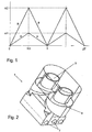
- the diagram of Fig. 1 shows a rotation angle-time curves A, B of the first and second actuator.
- the first actuator (curve A) has to run at a constant angular velocity up to a rotation angle ⁇ 1 at T / 2 to achieve such a full period of time T and then reset to its initial position (typically 0 °). become.
- the second actuator must run within the period T up to a rotation angle or2 and then back.
Landscapes
- Physics & Mathematics (AREA)
- Thermal Sciences (AREA)
- Engineering & Computer Science (AREA)
- Mechanical Engineering (AREA)
- Control Of Stepping Motors (AREA)
- Air-Conditioning For Vehicles (AREA)
- Control Of Vehicle Engines Or Engines For Specific Uses (AREA)
- Electrical Control Of Air Or Fuel Supplied To Internal-Combustion Engine (AREA)
- Motor Or Generator Cooling System (AREA)
- Vehicle Interior And Exterior Ornaments, Soundproofing, And Insulation (AREA)
- Sewage (AREA)
Abstract
Description
- Die Erfindung betrifft eine Vorrichtung zur Belüftung eines Fahrzeugs nach dem Oberbegriff des Anspruchs 1 und eine Verwendung dieser Vorrichtung.
-
WO 20051016673 A1 - Es ist die Aufgabe der Erfindung, eine Vorrichtung zur Belüftung eines Fahrzeugs anzugeben, bei der eine verbesserte Bewegungssteuerung eines Aktuators, insbesondere im Hinblick auf eine kontrollierbare Stellgeschwindigkeit des Aktuators, erzielt ist.
- Diese Aufgabe wird für eine eingangs genannte Vorrichtung erfindungsgemäß mit den kennzeichnenden Merkmalen des Anspruchs 1 gelöst. Durch die definierte Einstellung der Frequenz des Steuersignals zumindest eines Aktuators ist eine Anpassung der Geschwindigkeit des einen Aktuators an den anderen Aktuator und somit eine Synchronisation der Bewegungen der Aktuatoren erzielbar. Ganz allgemein wird hierdurch eine zielgerichtete Kombination der Bewegungen der beiden Aktuatoren ermöglicht.
- In vorteilhafter Ausführung umfasst zumindest einer der Aktuatoren einen Schrittmotor, wobei eine Anzahl von Pulsen des Steuersignals einer Anzahl von Stellschritten des Schrittmotors entspricht. Insbesondere vorteilhaft ist die Steuerelektronik des Aktuators bzw. Schrittmotors über einen Signalbus mit einem Hauptsteuergerät verbunden, wobei eine Sollfrequenz bzw. Soll-Schrittfrequenz des Steuersignals von dem Hauptsteuergerät an die Steuerelektronik übertragbar ist und wobei das Steuersignal für den Motor von der Steuerelektronik erzeugt wird. Hierdurch ist eine einfache technische Realisierung einer erfindungsgemäßen Vorrichtung ermöglicht, wobei eine hohe Belastung des Signalbusses durch die Übermittlung lediglich des Sollwertes der Schrittfrequenz vermieden wird. Durch die nachfolgende Generierung des mit der Frequenz gepulsten Steuersignals durch die Steuerelektronik ist eine nicht stockende Bewegung des als Schrittmotor ausgebildeten Aktuators bei zugleich einstellbar vorgegebener Schrittmotorgeschwindigkeit erzielt.
- In einer vorteilhaften Ausführung der Erfindung wird mittels zumindest einer der mechanischen Stellmöglichkeiten eine Umstellung eines Luftstroms einer ersten Ausströmdüse von einer gerichteten Einstellung zu einer diffusen Einstellung bewirkt. Alternativ oder ergänzend dazu kann es auch vorgesehen sein, dass mittels zumindest einer der mechanischen Stellmöglichkeiten ein Richtungsleitwerk einer Ausströmdüse in seiner Richtung einstellbar ist (Wedelbetrieb). Es können auch beliebige Kombination von zwei oder mehr Aktuatoren zueinander synchronisiert angesteuert werden, so dass ein beliebiger kombinierter Bewegungsablauf von Richtungsleitwerken oder Spot-Diffus-Umstellungen erreicht werden kann. Dies gilt auch für den Fall unterschiedlicher Drehwinkel der einzelnen Aktuatoren.
- Um einen Betrieb des Aktuators in einem kritischen Zustand, beispielsweise im Bereich einer mechanischen oder elektronischen Resonanzfrequenz, zu vermeiden, kann es vorgesehen sein, dass eine Auswahl von Frequenzen, insbesondere zumindest ein Frequenzbereich, von der Einstellbarkeit ausgenommen ist.
- Bevorzugt ist es vorgesehen, dass mittels einer Vorgabe der Schrittfrequenz eine oszillierende oder periodische Stellbewegung des Aktuators einstellbar ist. Besonders bevorzugt vollführen dabei der erste Aktuator als auch der zweite Aktuator eine oszillierende Stellbewegung, wobei durch die Vorgabe der Frequenz, insbesondere von zwei verschiedenen, den jeweiligen Aktuatoren zugeordneten Schrittfrequenzen, eine Synchronisation des einen Aktuators zu dem anderen Aktuator erzielt ist. Auf diese Weise kann zuverlässig und einfach eine oszillierende Umstellung zweier verschiedener Ausströmdüsen zwischen einem Spotbetrieb und einem Diffusbetrieb erfolgen. Alternativ oder ergänzend kann auch eine oszillierende Umstellung der Richtungsleitwerke zweier verschiedener Ausströmdüsen vorgesehen sein, welche durch die erfindungsgemäße Synchronisation der Aktuatoren zueinander synchron verläuft.
- Eine dem Erfindungsgedanken folgende Verwendung einer vorgenannten Vorrichtung wird durch die Merkmale des Anspruchs 9 angegeben. Allgemein kann eine erfindungsgemäße Vorrichtung vorteilhaft an Stellen Verwendung finden, an denen bisher mittels meist aufwendiger kinematischer Verbindungen oder Steuermitteln verschiedene, zueinander korrelierte Klappen verstellt werden. Dies kann die Einstellung der Luftverteilung einer Fahrzeug-Klimaanlage sein, etwa zur Regelung von Entfrostungs-, Fußraum- und Belüftungsklappen über einen gemeinsamen Stellmotors und eine die Klappen verbindende, gegebenenfalls einstellbare Kinematik. Durch die erfindungsgemäße Vorrichtung können solche zusammenhängenden Bewegungsabläufe auf einfache und kostengünstige Weise durch Verwendung mehrerer Aktuatoren nachgebildet werden, wobei regelmäßig zusätzliche Freiheitsgrade zur Verbesserung der Funktionsvielfalt hinzukommen. Ein weiteres konkretes Beispiel ist der Einsatz in Klimaanlagen mit bezüglich des Fahrzeugsraumes links-rechts-getrennter Luftverteilung, die bisher meist über eine zentrale Kinematik realisiert wird. Konstruktiv bedingte unterschiedliche Klappenwinkel für die linke und rechte Seite können durch die erfindungsgemäße Vorrichtung besonders einfach kompensiert werden. Ebenso ist zum Beispiel in einem sogenannten "Mono-Modus" einer zweizonigen Klimaregelung eine einfache Synchronisation der Luft- und/oder Temperaturklappen der linken und rechten Seite der Klimaanlage ermöglicht.
- Weitere Vorteile und Merkmale ergeben sich aus dem nachfolgend beschriebenen Ausführungsbeispiel sowie aus den abhängigen Ansprüchen.
- Nachfolgend wird ein bevorzugtes Ausführungsbeispiel einer erfindungsgemäßen Vorrichtung beschrieben und anhand der anliegenden Zeichnungen näher erläutert.
- Fig. 1
- zeigt ein Diagramm, in dem die Verstellwinkel von zwei erfindungsgemäß zueinander synchronisierten Aktuatoren von. Ausströmdüsen über die Zeit eingetragen sind.
- Fig. 2
- zeigt eine räumliche Ansicht einer Ausströmdüse einer erfindungsgemäßen Vorrichtung.
- Das bevorzugte Ausführungsbeispiel der erfindungsgemäßen Vorrichtung umfasst zwei Ausströmdüsen 1, die jeweils von der in Fig. 2 dargestellten Bauart sind. Jede dieser Ausströmdüsen 1 weist eine nicht dargestellte mechanische Stellmöglichkeit auf, über die einen jeweiligen ersten und zweiten Aktuator (nicht dargestellt) mit Luftklappen 2 der Ausströmdüsen 1 verbindbar ist. Die Luftklappen 2 bewirken je nach Stellung eine Luftausströmung nur durch einen zentralen, im Wesentlichen zylindrischen Ausströmbereich 3 oder nur durch einen randseitigen, spiraligen Ausströmbereich 4 oder durch beide Bereiche 3, 4. Das Ausströmen der Luft durch den zentralen Bereich 3 ist ein gerichtetes Ausströmen (Spot-Einstellung), wogegen das Ausströmen durch die randseitige Leiteinrichtung 4 ein diffuses Ausströmen ist. Durch geeignetes Betätigen der Klappen 2 über die Stellmöglichkeit und den Aktuator ist somit für jede der beiden Ausströmdüsen 1 eine kontinuierliche Umstellung zwischen einem Spotbetrieb und einem Diffusbetrieb möglich. Die Ausströmdüsen 1 unterscheiden sich im Allgemeinen in Details ihrer Ausformung und in der Auslegung der mechanischen Stellmöglichkeit. Hierdurch ist selbst bei baugleicher Ausführung der beiden Aktuatoren einer Verstellung der Ausströmdüsen 1 ein jeweils unterschiedlicher Drehwinkel der Aktuatoren zugeordnet. Die Aktuatoren sind Schrittmotoren, die über eine an ihnen angeordnete Steuerelektronik auf an sich bekannte Weise ansteuerbar sind. Die Steuerelektronik umfasst im allgemeinen einen Mikroprozessor und/oder einen ASIC. In der Steuerelektronik wird ein im Wesentlichen pulsförmiges Steuersignal für die Schrittmotoren erzeugt (Schrittmuster), wobei jeder der Pulse einen Schritt des Schrittmotors bewirkt. Somit ist die Drehgeschwindigkeit des Motors proportional zu der Frequenz des gepulsten Steuersignals.
- Die jeweilige Steuerelektronik des jeweiligen Schrittmotors ist über ein Signalbussystem des Kraftfahrzeugs mit einem zentralen Hauptsteuergerät verbunden. Durch Übermittlung von Daten von dem Hauptsteuergerät an die Steuerelektroniken der Schrittmotoren kann sowohl die Laufweite (Gesamtpulszahl) als auch die Laufgeschwindigkeit, nämlich die Frequenz des Steuersignals, eingestellt werden. Die Parametrisierung kann dabei auch eine indirekte sein, z. B. indem nicht die Gesamtpulszahl zur Einstellung der Laufweite übermittelt wird, sondern die Laufdauer, welche bei gegebener Frequenz der Laufweite entspricht.
- Das Hauptsteuergerät erteilt über den Signalbus den Befehl, den ersten Schrittmotor mit einer ersten Frequenz f1 und den zweiten Schrittmotor mit einer zweiten Frequenz f2 zu starten, wobei eine Laufweite von f1*T Schritten des ersten Motors und von f2*T Schritten des zweiten Motors erfolgen soll. T ist dabei die Periodendauer einer Oszillation zwischen Spot- und Diffuseinstellung eines oszillierenden Betriebsmodus der Ausströmdüsen. Ziel ist es dabei, dass nach der Zeit T jede der Ausströmdüsen in ihre Ausgangsstellung zurückgekehrt ist und zwischenzeitlich eine vollständige Umschaltung zwischen diffusem Betrieb und Spotbetrieb stattgefunden hat. Nach Erhalt des Befehls wird von der jeweiligen Steuerelektronik das Steuersignal für den jeweiligen Schrittmotor generiert und die erforderliche Anzahl von Pulsen aufrecht erhalten. Nach Ende einer Periode, die durchaus bis zu mehreren Sekunden dauern kann, kann eine Kontrollabfrage nach dem Vorliegen einer gewünschten Ausgangsstellung erfolgen, wonach eine weitere Oszillation gestartet werden kann. Die Kontrollabfrage ist vorteilhaft, aber nicht unbedingt erforderlich.
- Das Diagramm aus Fig. 1 zeigt eine Drehwinkel-Zeit-Kurven A, B des ersten bzw. zweiten Aktuators. Wie dem Diagramm entnommen werden kann, muss der erste Aktuator (Kurve A) zur Erzielung einer solchen vollen Periode der Dauer T mit konstanter Winkelgeschwindigkeit bis zu einem Drehwinkel α1 bei T/2 laufen und nachfolgend auf seine Ausgangsstellung (typisch: 0°) zurückgestellt .werden. Der zweite Aktuator muss innerhalb der Periodendauer T bis zu einem Drehwinkel or2 und dann zurück laufen. Die hierzu erforderlichen unterschiedlichen Drehgeschwindigkeiten der beiden Aktuatoren werden durch die unterschiedlichen Frequenzen f1, f2 der Steuersignale realisiert, wobei unter der Bedingung der Synchronisation (gleiche Periodendauer T für beide Verstellungen) gilt: α1 : α2 = f1 : f2.
Claims (9)
- Vorrichtung zur Belüftung eines Fahrzeugs, umfassend
eine einstellbare Luftleitvorrichtung (1) mit mindestens einer ersten und einer zweiten mechanischen Stellmöglichkeit (2),
einen ersten und zumindest einen zweiten elektromechanischen Aktuator, wobei jeder der Aktuatoren jeweils einer der Stellmöglichkeiten (2) als Antrieb zugeordnet ist, und
eine Steuerelektronik zur Ansteuerung der Aktuatoren,
wobei eine Stellgeschwindigkeit von zumindest einem der Aktuatoren von der Frequenz (f1, f2) eines dem Aktuator zugeführten Steuersignals abhängt,
dadurch gekennzeichnet,
dass die Frequenz (f1, f2) des Steuersignals des einen Aktuators zumindest in einem bestimmten Betriebsmodus auf eine Stellgeschwindigkeit des anderen Aktuators abgestimmt ist. - Vorrichtung nach Anspruch 1, dadurch gekennzeichnet, dass zumindest einer der Aktuatoren einen Schrittmotor umfasst, wobei eine Anzahl von Pulsen des Steuersignals einer Anzahl von Stellschritten des Aktuators entspricht.
- Vorrichtung nach Anspruch 2, dadurch gekennzeichnet, dass die Steuerelektronik über einen Signalbus mit einem Hauptsteuergerät verbunden ist, wobei eine Sollfrequenz des Steuersignals von dem Hauptsteuergerät über den Signalbus an die Steuerelektronik übertragbar ist und wobei das Steuersignal von der Steuerelektronik erzeugt wird.
- Vorrichtung nach einem der vorhergehenden Ansprüche, dadurch gekennzeichnet, dass mittels zumindest einer der mechanischen Stellmöglichkeiten (2) eine Umstellung eines Luftstroms einer ersten Ausströmdüse (1) von einer gerichteten Einstellung (3) zu einer diffusen Einstellung (4) bewirkt wird.
- Vorrichtung nach einem der vorhergehenden Ansprüche, dadurch gekennzeichnet, dass mittels zumindest einer der mechanischen Stellmöglichkeiten (2) ein Richtungsleitwerk einer Ausströmdüse in seiner Richtung einstellbar ist.
- Vorrichtung nach einem der vorhergehenden Ansprüche, dadurch gekennzeichnet, dass eine Auswahl von Frequenzen, insbesondere zumindest ein Frequenzbereich, von der Einstellbarkeit ausgenommen ist.
- Vorrichtung nach einem der vorhergehenden Ansprüche, dadurch gekennzeichnet, dass mittels einer Vorgabe der Frequenz (f1, f2) eine oszillierende oder periodische Stellbewegung des Aktuators regelbar ist.
- Vorrichtung nach Anspruch 7, dadurch gekennzeichnet, dass sowohl der erste Aktuator als auch der zweite Aktuator eine oszillierende oder periodische Stellbewegung vollführen, wobei durch die Vorgabe der Frequenz, insbesondere von zwei verschiedenen, den jeweiligen Aktuatoren zugeordneten Frequenzen, eine Synchronisation des einen Aktuators zu dem anderen Aktuator erzielt ist.
- Verwendung einer Vorrichtung nach Anspruch 1 zur Ansteuerung von Bewegungen zumindest zweier Steuerklappen eines Luftsteuersystems eines Kraftfahrzeugs, die auf herkömmliche Weise über eine Verbindungskinematik in ihrer Bewegung relativ zueinander gesteuert sind.
Applications Claiming Priority (1)
| Application Number | Priority Date | Filing Date | Title |
|---|---|---|---|
| DE102005040993A DE102005040993A1 (de) | 2005-08-29 | 2005-08-29 | Vorrichtung zur Belüftung eines Fahrzeugs |
Publications (2)
| Publication Number | Publication Date |
|---|---|
| EP1759898A1 true EP1759898A1 (de) | 2007-03-07 |
| EP1759898B1 EP1759898B1 (de) | 2009-09-09 |
Family
ID=37106266
Family Applications (1)
| Application Number | Title | Priority Date | Filing Date |
|---|---|---|---|
| EP06015333A Expired - Lifetime EP1759898B1 (de) | 2005-08-29 | 2006-07-24 | Vorrichtung zur Belüftung eines Fahrzeugs |
Country Status (3)
| Country | Link |
|---|---|
| EP (1) | EP1759898B1 (de) |
| AT (1) | ATE442272T1 (de) |
| DE (2) | DE102005040993A1 (de) |
Citations (4)
| Publication number | Priority date | Publication date | Assignee | Title |
|---|---|---|---|---|
| DE19918515A1 (de) * | 1999-04-23 | 2000-10-26 | Daimler Chrysler Ag | Einrichtung zum Zuführen von Luft in die Fahrgastzelle von Fahrzeugen |
| US6170274B1 (en) * | 1998-05-13 | 2001-01-09 | Denso Corporation | Vehicle air-conditioning system with automatic louver oscillation control |
| WO2005016673A1 (de) * | 2003-08-11 | 2005-02-24 | Behr Gmbh & Co. Kg | Luftausströmer, insbesondere für ein kraftfahrzeug |
| EP1535768A2 (de) * | 2003-11-26 | 2005-06-01 | Volkswagen Aktiengesellschaft | Vorrichtung und Verfahren zur Einstellung eines Stellgliedes |
Family Cites Families (2)
| Publication number | Priority date | Publication date | Assignee | Title |
|---|---|---|---|---|
| DE10121904A1 (de) * | 2001-05-03 | 2002-11-14 | Buhler Motor Gmbh | Belüftungsvorrichtung für Fahrzeuge |
| DE10350232A1 (de) * | 2003-10-27 | 2005-05-19 | Behr Gmbh & Co. Kg | Luftausströmer für Kraftfahrzeuge |
-
2005
- 2005-08-29 DE DE102005040993A patent/DE102005040993A1/de not_active Withdrawn
-
2006
- 2006-07-24 DE DE502006004780T patent/DE502006004780D1/de not_active Expired - Lifetime
- 2006-07-24 AT AT06015333T patent/ATE442272T1/de active
- 2006-07-24 EP EP06015333A patent/EP1759898B1/de not_active Expired - Lifetime
Patent Citations (4)
| Publication number | Priority date | Publication date | Assignee | Title |
|---|---|---|---|---|
| US6170274B1 (en) * | 1998-05-13 | 2001-01-09 | Denso Corporation | Vehicle air-conditioning system with automatic louver oscillation control |
| DE19918515A1 (de) * | 1999-04-23 | 2000-10-26 | Daimler Chrysler Ag | Einrichtung zum Zuführen von Luft in die Fahrgastzelle von Fahrzeugen |
| WO2005016673A1 (de) * | 2003-08-11 | 2005-02-24 | Behr Gmbh & Co. Kg | Luftausströmer, insbesondere für ein kraftfahrzeug |
| EP1535768A2 (de) * | 2003-11-26 | 2005-06-01 | Volkswagen Aktiengesellschaft | Vorrichtung und Verfahren zur Einstellung eines Stellgliedes |
Also Published As
| Publication number | Publication date |
|---|---|
| DE102005040993A1 (de) | 2007-03-08 |
| EP1759898B1 (de) | 2009-09-09 |
| DE502006004780D1 (de) | 2009-10-22 |
| ATE442272T1 (de) | 2009-09-15 |
Similar Documents
| Publication | Publication Date | Title |
|---|---|---|
| DE3820431C2 (de) | ||
| DE102015112378B4 (de) | System zur Luftverteilung einer Klimaanlage eines Kraftfahrzeugs und Verfahren zum Betreiben des Systems | |
| EP3941766B1 (de) | Belüftungsanordnung zur belüftung eines kraftfahrzeuginnenraums | |
| EP0116904A1 (de) | Antriebsvorrichtung für eine Klappe in Kraftfahrzeugen | |
| EP1708899B1 (de) | Stellvorrichtung und heizungs- oder klimatisierungseinrichtung | |
| EP1306241B1 (de) | Fahrzeugheiz- und Klimaanlage mit kombinierter Luftmisch- und -verteilklappe | |
| EP1759898B1 (de) | Vorrichtung zur Belüftung eines Fahrzeugs | |
| DE102014210264A1 (de) | Klimaanlage und Verfahren zur Lufttemperierung | |
| DE102008016238A1 (de) | Lüftdüse | |
| EP3645322A1 (de) | Verfahren und vorrichtung zur steuerung von klimatisierungseinrichtungen in einem kraftfahrzeug | |
| DE3211962A1 (de) | Verfahren und einrichtung zum regeln von klappen einer lueftungs- und temperaturregelanlage fuer ein fahrzeug | |
| EP1531068B1 (de) | Kraftfahrzeug-Klimaanlage | |
| DE10310022B4 (de) | Vorrichtung und Verfahren für eine Klimatisierung der hinteren Sitzplätze in einem Fahrzeug | |
| DE4110229A1 (de) | Heiz- und/oder klimaanlage fuer den innenraum eines personenkraftwagens | |
| DE19750160B4 (de) | Innenluft/Außenluft-Schaltvorrichtung mit Staudruck-Regeleinheit für eine Klimaanlage für ein Fahrzeug | |
| DE102021002008A1 (de) | Luftausströmer für ein Fahrzeug | |
| DE19704432C1 (de) | Heizungs- oder Klimaanlage | |
| EP1002677A1 (de) | Heiz- und/oder Klimaanlage für ein Kraftfahrzeug | |
| DE2914180C2 (de) | Regelvorrichtung für eine Heizungs- oder Klimaanlage, insbesondere für Kraftfahrzeuge | |
| EP0876930A2 (de) | Klimaanlage für den Innenraum eines Fahrzeuges | |
| EP1187733A1 (de) | Vorrichtung zur regelung der innenraumtemperatur eines kraftfahrzeuges | |
| EP1738941A1 (de) | Kraftfahrzeug-Klimaanlage | |
| EP2011676A2 (de) | Klimaanlage | |
| EP1479545B1 (de) | Klimaanlage, insbesondere für Fahrzeuge sowie Verfahren zur Klimatisierung | |
| DE102004035570A1 (de) | Klimaanlage eines Kraftfahrzeugs |
Legal Events
| Date | Code | Title | Description |
|---|---|---|---|
| PUAI | Public reference made under article 153(3) epc to a published international application that has entered the european phase |
Free format text: ORIGINAL CODE: 0009012 |
|
| AK | Designated contracting states |
Kind code of ref document: A1 Designated state(s): AT BE BG CH CY CZ DE DK EE ES FI FR GB GR HU IE IS IT LI LT LU LV MC NL PL PT RO SE SI SK TR |
|
| AX | Request for extension of the european patent |
Extension state: AL BA HR MK YU |
|
| 17P | Request for examination filed |
Effective date: 20070907 |
|
| 17Q | First examination report despatched |
Effective date: 20071011 |
|
| AKX | Designation fees paid |
Designated state(s): AT BE BG CH CY CZ DE DK EE ES FI FR GB GR HU IE IS IT LI LT LU LV MC NL PL PT RO SE SI SK TR |
|
| GRAP | Despatch of communication of intention to grant a patent |
Free format text: ORIGINAL CODE: EPIDOSNIGR1 |
|
| GRAS | Grant fee paid |
Free format text: ORIGINAL CODE: EPIDOSNIGR3 |
|
| GRAA | (expected) grant |
Free format text: ORIGINAL CODE: 0009210 |
|
| AK | Designated contracting states |
Kind code of ref document: B1 Designated state(s): AT BE BG CH CY CZ DE DK EE ES FI FR GB GR HU IE IS IT LI LT LU LV MC NL PL PT RO SE SI SK TR |
|
| REG | Reference to a national code |
Ref country code: GB Ref legal event code: FG4D Free format text: NOT ENGLISH |
|
| REG | Reference to a national code |
Ref country code: CH Ref legal event code: EP |
|
| REG | Reference to a national code |
Ref country code: IE Ref legal event code: FG4D |
|
| REF | Corresponds to: |
Ref document number: 502006004780 Country of ref document: DE Date of ref document: 20091022 Kind code of ref document: P |
|
| PG25 | Lapsed in a contracting state [announced via postgrant information from national office to epo] |
Ref country code: FI Free format text: LAPSE BECAUSE OF FAILURE TO SUBMIT A TRANSLATION OF THE DESCRIPTION OR TO PAY THE FEE WITHIN THE PRESCRIBED TIME-LIMIT Effective date: 20090909 Ref country code: LT Free format text: LAPSE BECAUSE OF FAILURE TO SUBMIT A TRANSLATION OF THE DESCRIPTION OR TO PAY THE FEE WITHIN THE PRESCRIBED TIME-LIMIT Effective date: 20090909 Ref country code: SE Free format text: LAPSE BECAUSE OF FAILURE TO SUBMIT A TRANSLATION OF THE DESCRIPTION OR TO PAY THE FEE WITHIN THE PRESCRIBED TIME-LIMIT Effective date: 20090909 |
|
| NLV1 | Nl: lapsed or annulled due to failure to fulfill the requirements of art. 29p and 29m of the patents act | ||
| LTIE | Lt: invalidation of european patent or patent extension |
Effective date: 20090909 |
|
| PG25 | Lapsed in a contracting state [announced via postgrant information from national office to epo] |
Ref country code: SI Free format text: LAPSE BECAUSE OF FAILURE TO SUBMIT A TRANSLATION OF THE DESCRIPTION OR TO PAY THE FEE WITHIN THE PRESCRIBED TIME-LIMIT Effective date: 20090909 Ref country code: PL Free format text: LAPSE BECAUSE OF FAILURE TO SUBMIT A TRANSLATION OF THE DESCRIPTION OR TO PAY THE FEE WITHIN THE PRESCRIBED TIME-LIMIT Effective date: 20090909 Ref country code: NL Free format text: LAPSE BECAUSE OF FAILURE TO SUBMIT A TRANSLATION OF THE DESCRIPTION OR TO PAY THE FEE WITHIN THE PRESCRIBED TIME-LIMIT Effective date: 20090909 Ref country code: LV Free format text: LAPSE BECAUSE OF FAILURE TO SUBMIT A TRANSLATION OF THE DESCRIPTION OR TO PAY THE FEE WITHIN THE PRESCRIBED TIME-LIMIT Effective date: 20090909 |
|
| PG25 | Lapsed in a contracting state [announced via postgrant information from national office to epo] |
Ref country code: CY Free format text: LAPSE BECAUSE OF FAILURE TO SUBMIT A TRANSLATION OF THE DESCRIPTION OR TO PAY THE FEE WITHIN THE PRESCRIBED TIME-LIMIT Effective date: 20090909 |
|
| REG | Reference to a national code |
Ref country code: IE Ref legal event code: FD4D |
|
| PG25 | Lapsed in a contracting state [announced via postgrant information from national office to epo] |
Ref country code: RO Free format text: LAPSE BECAUSE OF FAILURE TO SUBMIT A TRANSLATION OF THE DESCRIPTION OR TO PAY THE FEE WITHIN THE PRESCRIBED TIME-LIMIT Effective date: 20090909 Ref country code: PT Free format text: LAPSE BECAUSE OF FAILURE TO SUBMIT A TRANSLATION OF THE DESCRIPTION OR TO PAY THE FEE WITHIN THE PRESCRIBED TIME-LIMIT Effective date: 20100111 Ref country code: EE Free format text: LAPSE BECAUSE OF FAILURE TO SUBMIT A TRANSLATION OF THE DESCRIPTION OR TO PAY THE FEE WITHIN THE PRESCRIBED TIME-LIMIT Effective date: 20090909 Ref country code: ES Free format text: LAPSE BECAUSE OF FAILURE TO SUBMIT A TRANSLATION OF THE DESCRIPTION OR TO PAY THE FEE WITHIN THE PRESCRIBED TIME-LIMIT Effective date: 20091220 Ref country code: IE Free format text: LAPSE BECAUSE OF FAILURE TO SUBMIT A TRANSLATION OF THE DESCRIPTION OR TO PAY THE FEE WITHIN THE PRESCRIBED TIME-LIMIT Effective date: 20090909 Ref country code: IS Free format text: LAPSE BECAUSE OF FAILURE TO SUBMIT A TRANSLATION OF THE DESCRIPTION OR TO PAY THE FEE WITHIN THE PRESCRIBED TIME-LIMIT Effective date: 20100109 Ref country code: CZ Free format text: LAPSE BECAUSE OF FAILURE TO SUBMIT A TRANSLATION OF THE DESCRIPTION OR TO PAY THE FEE WITHIN THE PRESCRIBED TIME-LIMIT Effective date: 20090909 |
|
| PG25 | Lapsed in a contracting state [announced via postgrant information from national office to epo] |
Ref country code: SK Free format text: LAPSE BECAUSE OF FAILURE TO SUBMIT A TRANSLATION OF THE DESCRIPTION OR TO PAY THE FEE WITHIN THE PRESCRIBED TIME-LIMIT Effective date: 20090909 |
|
| PLBE | No opposition filed within time limit |
Free format text: ORIGINAL CODE: 0009261 |
|
| STAA | Information on the status of an ep patent application or granted ep patent |
Free format text: STATUS: NO OPPOSITION FILED WITHIN TIME LIMIT |
|
| PG25 | Lapsed in a contracting state [announced via postgrant information from national office to epo] |
Ref country code: DK Free format text: LAPSE BECAUSE OF FAILURE TO SUBMIT A TRANSLATION OF THE DESCRIPTION OR TO PAY THE FEE WITHIN THE PRESCRIBED TIME-LIMIT Effective date: 20090909 |
|
| 26N | No opposition filed |
Effective date: 20100610 |
|
| PG25 | Lapsed in a contracting state [announced via postgrant information from national office to epo] |
Ref country code: GR Free format text: LAPSE BECAUSE OF FAILURE TO SUBMIT A TRANSLATION OF THE DESCRIPTION OR TO PAY THE FEE WITHIN THE PRESCRIBED TIME-LIMIT Effective date: 20091210 |
|
| PGFP | Annual fee paid to national office [announced via postgrant information from national office to epo] |
Ref country code: FR Payment date: 20100802 Year of fee payment: 5 |
|
| BERE | Be: lapsed |
Owner name: BEHR G.M.B.H. & CO. KG Effective date: 20100731 |
|
| PG25 | Lapsed in a contracting state [announced via postgrant information from national office to epo] |
Ref country code: MC Free format text: LAPSE BECAUSE OF NON-PAYMENT OF DUE FEES Effective date: 20100731 |
|
| REG | Reference to a national code |
Ref country code: CH Ref legal event code: PL |
|
| GBPC | Gb: european patent ceased through non-payment of renewal fee |
Effective date: 20100724 |
|
| PG25 | Lapsed in a contracting state [announced via postgrant information from national office to epo] |
Ref country code: IT Free format text: LAPSE BECAUSE OF FAILURE TO SUBMIT A TRANSLATION OF THE DESCRIPTION OR TO PAY THE FEE WITHIN THE PRESCRIBED TIME-LIMIT Effective date: 20090909 |
|
| PG25 | Lapsed in a contracting state [announced via postgrant information from national office to epo] |
Ref country code: CH Free format text: LAPSE BECAUSE OF NON-PAYMENT OF DUE FEES Effective date: 20100731 Ref country code: LI Free format text: LAPSE BECAUSE OF NON-PAYMENT OF DUE FEES Effective date: 20100731 |
|
| PG25 | Lapsed in a contracting state [announced via postgrant information from national office to epo] |
Ref country code: BE Free format text: LAPSE BECAUSE OF NON-PAYMENT OF DUE FEES Effective date: 20100731 |
|
| PG25 | Lapsed in a contracting state [announced via postgrant information from national office to epo] |
Ref country code: GB Free format text: LAPSE BECAUSE OF NON-PAYMENT OF DUE FEES Effective date: 20100724 |
|
| REG | Reference to a national code |
Ref country code: FR Ref legal event code: ST Effective date: 20120330 |
|
| PG25 | Lapsed in a contracting state [announced via postgrant information from national office to epo] |
Ref country code: FR Free format text: LAPSE BECAUSE OF NON-PAYMENT OF DUE FEES Effective date: 20110801 |
|
| PG25 | Lapsed in a contracting state [announced via postgrant information from national office to epo] |
Ref country code: HU Free format text: LAPSE BECAUSE OF FAILURE TO SUBMIT A TRANSLATION OF THE DESCRIPTION OR TO PAY THE FEE WITHIN THE PRESCRIBED TIME-LIMIT Effective date: 20100310 Ref country code: LU Free format text: LAPSE BECAUSE OF NON-PAYMENT OF DUE FEES Effective date: 20100724 Ref country code: BG Free format text: LAPSE BECAUSE OF FAILURE TO SUBMIT A TRANSLATION OF THE DESCRIPTION OR TO PAY THE FEE WITHIN THE PRESCRIBED TIME-LIMIT Effective date: 20090909 |
|
| PG25 | Lapsed in a contracting state [announced via postgrant information from national office to epo] |
Ref country code: TR Free format text: LAPSE BECAUSE OF FAILURE TO SUBMIT A TRANSLATION OF THE DESCRIPTION OR TO PAY THE FEE WITHIN THE PRESCRIBED TIME-LIMIT Effective date: 20090909 |
|
| REG | Reference to a national code |
Ref country code: AT Ref legal event code: MM01 Ref document number: 442272 Country of ref document: AT Kind code of ref document: T Effective date: 20110724 |
|
| PG25 | Lapsed in a contracting state [announced via postgrant information from national office to epo] |
Ref country code: AT Free format text: LAPSE BECAUSE OF NON-PAYMENT OF DUE FEES Effective date: 20110724 |
|
| REG | Reference to a national code |
Ref country code: DE Ref legal event code: R082 Ref document number: 502006004780 Country of ref document: DE Representative=s name: GRAUEL, ANDREAS, DIPL.-PHYS. DR. RER. NAT., DE |
|
| REG | Reference to a national code |
Ref country code: DE Ref legal event code: R082 Ref document number: 502006004780 Country of ref document: DE Representative=s name: GRAUEL, ANDREAS, DIPL.-PHYS. DR. RER. NAT., DE Effective date: 20150223 Ref country code: DE Ref legal event code: R081 Ref document number: 502006004780 Country of ref document: DE Owner name: MAHLE INTERNATIONAL GMBH, DE Free format text: FORMER OWNER: BEHR GMBH & CO. KG, 70469 STUTTGART, DE Effective date: 20150223 |
|
| PGFP | Annual fee paid to national office [announced via postgrant information from national office to epo] |
Ref country code: DE Payment date: 20190919 Year of fee payment: 14 |
|
| REG | Reference to a national code |
Ref country code: DE Ref legal event code: R119 Ref document number: 502006004780 Country of ref document: DE |
|
| PG25 | Lapsed in a contracting state [announced via postgrant information from national office to epo] |
Ref country code: DE Free format text: LAPSE BECAUSE OF NON-PAYMENT OF DUE FEES Effective date: 20210202 |