EP1759785A1 - Method and device for supply of connecting elements to a processing apparatus - Google Patents
Method and device for supply of connecting elements to a processing apparatus Download PDFInfo
- Publication number
- EP1759785A1 EP1759785A1 EP06017725A EP06017725A EP1759785A1 EP 1759785 A1 EP1759785 A1 EP 1759785A1 EP 06017725 A EP06017725 A EP 06017725A EP 06017725 A EP06017725 A EP 06017725A EP 1759785 A1 EP1759785 A1 EP 1759785A1
- Authority
- EP
- European Patent Office
- Prior art keywords
- connecting elements
- passage
- intermediate reservoir
- reservoir
- chamber
- Prior art date
- Legal status (The legal status is an assumption and is not a legal conclusion. Google has not performed a legal analysis and makes no representation as to the accuracy of the status listed.)
- Granted
Links
- 238000012545 processing Methods 0.000 title claims abstract description 42
- 238000000034 method Methods 0.000 title claims abstract description 26
- 238000003860 storage Methods 0.000 claims abstract description 51
- 230000004888 barrier function Effects 0.000 claims description 6
- 230000000977 initiatory effect Effects 0.000 claims description 5
- 238000004891 communication Methods 0.000 description 2
- 238000004519 manufacturing process Methods 0.000 description 2
- 239000002184 metal Substances 0.000 description 2
- 230000005540 biological transmission Effects 0.000 description 1
- 230000003750 conditioning effect Effects 0.000 description 1
- 238000010276 construction Methods 0.000 description 1
- 230000003111 delayed effect Effects 0.000 description 1
- 238000006073 displacement reaction Methods 0.000 description 1
- 230000000694 effects Effects 0.000 description 1
- 238000012423 maintenance Methods 0.000 description 1
- 238000012986 modification Methods 0.000 description 1
- 230000004048 modification Effects 0.000 description 1
- 210000002445 nipple Anatomy 0.000 description 1
- 230000003287 optical effect Effects 0.000 description 1
- 230000000149 penetrating effect Effects 0.000 description 1
- 238000004886 process control Methods 0.000 description 1
- 229920002994 synthetic fiber Polymers 0.000 description 1
- 238000012546 transfer Methods 0.000 description 1
- 238000003466 welding Methods 0.000 description 1
Images


Classifications
-
- B—PERFORMING OPERATIONS; TRANSPORTING
- B23—MACHINE TOOLS; METAL-WORKING NOT OTHERWISE PROVIDED FOR
- B23P—METAL-WORKING NOT OTHERWISE PROVIDED FOR; COMBINED OPERATIONS; UNIVERSAL MACHINE TOOLS
- B23P19/00—Machines for simply fitting together or separating metal parts or objects, or metal and non-metal parts, whether or not involving some deformation; Tools or devices therefor so far as not provided for in other classes
- B23P19/001—Article feeders for assembling machines
-
- B—PERFORMING OPERATIONS; TRANSPORTING
- B21—MECHANICAL METAL-WORKING WITHOUT ESSENTIALLY REMOVING MATERIAL; PUNCHING METAL
- B21J—FORGING; HAMMERING; PRESSING METAL; RIVETING; FORGE FURNACES
- B21J15/00—Riveting
- B21J15/10—Riveting machines
- B21J15/16—Drives for riveting machines; Transmission means therefor
- B21J15/18—Drives for riveting machines; Transmission means therefor operated by air pressure or other gas pressure, e.g. explosion pressure
-
- B—PERFORMING OPERATIONS; TRANSPORTING
- B21—MECHANICAL METAL-WORKING WITHOUT ESSENTIALLY REMOVING MATERIAL; PUNCHING METAL
- B21J—FORGING; HAMMERING; PRESSING METAL; RIVETING; FORGE FURNACES
- B21J15/00—Riveting
- B21J15/10—Riveting machines
- B21J15/30—Particular elements, e.g. supports; Suspension equipment specially adapted for portable riveters
- B21J15/32—Devices for inserting or holding rivets in position with or without feeding arrangements
-
- B—PERFORMING OPERATIONS; TRANSPORTING
- B21—MECHANICAL METAL-WORKING WITHOUT ESSENTIALLY REMOVING MATERIAL; PUNCHING METAL
- B21J—FORGING; HAMMERING; PRESSING METAL; RIVETING; FORGE FURNACES
- B21J15/00—Riveting
- B21J15/10—Riveting machines
- B21J15/36—Rivet sets, i.e. tools for forming heads; Mandrels for expanding parts of hollow rivets
-
- B—PERFORMING OPERATIONS; TRANSPORTING
- B23—MACHINE TOOLS; METAL-WORKING NOT OTHERWISE PROVIDED FOR
- B23P—METAL-WORKING NOT OTHERWISE PROVIDED FOR; COMBINED OPERATIONS; UNIVERSAL MACHINE TOOLS
- B23P19/00—Machines for simply fitting together or separating metal parts or objects, or metal and non-metal parts, whether or not involving some deformation; Tools or devices therefor so far as not provided for in other classes
- B23P19/001—Article feeders for assembling machines
- B23P19/003—Escapement mechanisms used therewith
-
- Y—GENERAL TAGGING OF NEW TECHNOLOGICAL DEVELOPMENTS; GENERAL TAGGING OF CROSS-SECTIONAL TECHNOLOGIES SPANNING OVER SEVERAL SECTIONS OF THE IPC; TECHNICAL SUBJECTS COVERED BY FORMER USPC CROSS-REFERENCE ART COLLECTIONS [XRACs] AND DIGESTS
- Y10—TECHNICAL SUBJECTS COVERED BY FORMER USPC
- Y10T—TECHNICAL SUBJECTS COVERED BY FORMER US CLASSIFICATION
- Y10T29/00—Metal working
- Y10T29/49—Method of mechanical manufacture
- Y10T29/49002—Electrical device making
- Y10T29/49007—Indicating transducer
-
- Y—GENERAL TAGGING OF NEW TECHNOLOGICAL DEVELOPMENTS; GENERAL TAGGING OF CROSS-SECTIONAL TECHNOLOGIES SPANNING OVER SEVERAL SECTIONS OF THE IPC; TECHNICAL SUBJECTS COVERED BY FORMER USPC CROSS-REFERENCE ART COLLECTIONS [XRACs] AND DIGESTS
- Y10—TECHNICAL SUBJECTS COVERED BY FORMER USPC
- Y10T—TECHNICAL SUBJECTS COVERED BY FORMER US CLASSIFICATION
- Y10T29/00—Metal working
- Y10T29/49—Method of mechanical manufacture
- Y10T29/49826—Assembling or joining
- Y10T29/49833—Punching, piercing or reaming part by surface of second part
- Y10T29/49835—Punching, piercing or reaming part by surface of second part with shaping
- Y10T29/49837—Punching, piercing or reaming part by surface of second part with shaping of first part
-
- Y—GENERAL TAGGING OF NEW TECHNOLOGICAL DEVELOPMENTS; GENERAL TAGGING OF CROSS-SECTIONAL TECHNOLOGIES SPANNING OVER SEVERAL SECTIONS OF THE IPC; TECHNICAL SUBJECTS COVERED BY FORMER USPC CROSS-REFERENCE ART COLLECTIONS [XRACs] AND DIGESTS
- Y10—TECHNICAL SUBJECTS COVERED BY FORMER USPC
- Y10T—TECHNICAL SUBJECTS COVERED BY FORMER US CLASSIFICATION
- Y10T29/00—Metal working
- Y10T29/49—Method of mechanical manufacture
- Y10T29/49826—Assembling or joining
- Y10T29/49908—Joining by deforming
- Y10T29/49938—Radially expanding part in cavity, aperture, or hollow body
- Y10T29/49943—Riveting
-
- Y—GENERAL TAGGING OF NEW TECHNOLOGICAL DEVELOPMENTS; GENERAL TAGGING OF CROSS-SECTIONAL TECHNOLOGIES SPANNING OVER SEVERAL SECTIONS OF THE IPC; TECHNICAL SUBJECTS COVERED BY FORMER USPC CROSS-REFERENCE ART COLLECTIONS [XRACs] AND DIGESTS
- Y10—TECHNICAL SUBJECTS COVERED BY FORMER USPC
- Y10T—TECHNICAL SUBJECTS COVERED BY FORMER US CLASSIFICATION
- Y10T29/00—Metal working
- Y10T29/49—Method of mechanical manufacture
- Y10T29/49826—Assembling or joining
- Y10T29/49947—Assembling or joining by applying separate fastener
- Y10T29/49954—Fastener deformed after application
- Y10T29/49956—Riveting
-
- Y—GENERAL TAGGING OF NEW TECHNOLOGICAL DEVELOPMENTS; GENERAL TAGGING OF CROSS-SECTIONAL TECHNOLOGIES SPANNING OVER SEVERAL SECTIONS OF THE IPC; TECHNICAL SUBJECTS COVERED BY FORMER USPC CROSS-REFERENCE ART COLLECTIONS [XRACs] AND DIGESTS
- Y10—TECHNICAL SUBJECTS COVERED BY FORMER USPC
- Y10T—TECHNICAL SUBJECTS COVERED BY FORMER US CLASSIFICATION
- Y10T29/00—Metal working
- Y10T29/51—Plural diverse manufacturing apparatus including means for metal shaping or assembling
- Y10T29/5116—Plural diverse manufacturing apparatus including means for metal shaping or assembling forging and bending, cutting or punching
- Y10T29/5118—Riveting
-
- Y—GENERAL TAGGING OF NEW TECHNOLOGICAL DEVELOPMENTS; GENERAL TAGGING OF CROSS-SECTIONAL TECHNOLOGIES SPANNING OVER SEVERAL SECTIONS OF THE IPC; TECHNICAL SUBJECTS COVERED BY FORMER USPC CROSS-REFERENCE ART COLLECTIONS [XRACs] AND DIGESTS
- Y10—TECHNICAL SUBJECTS COVERED BY FORMER USPC
- Y10T—TECHNICAL SUBJECTS COVERED BY FORMER US CLASSIFICATION
- Y10T29/00—Metal working
- Y10T29/53—Means to assemble or disassemble
- Y10T29/5343—Means to drive self-piercing work part
-
- Y—GENERAL TAGGING OF NEW TECHNOLOGICAL DEVELOPMENTS; GENERAL TAGGING OF CROSS-SECTIONAL TECHNOLOGIES SPANNING OVER SEVERAL SECTIONS OF THE IPC; TECHNICAL SUBJECTS COVERED BY FORMER USPC CROSS-REFERENCE ART COLLECTIONS [XRACs] AND DIGESTS
- Y10—TECHNICAL SUBJECTS COVERED BY FORMER USPC
- Y10T—TECHNICAL SUBJECTS COVERED BY FORMER US CLASSIFICATION
- Y10T29/00—Metal working
- Y10T29/53—Means to assemble or disassemble
- Y10T29/53709—Overedge assembling means
- Y10T29/5377—Riveter
Definitions
- the invention relates to a method of supplying connecting elements to a processing apparatus, in which the connecting elements are placed in readiness by a supplying apparatus and individually conveyed to a loading device arranged on the processing apparatus.
- the invention relates further to a device for supply of connecting elements to a processing apparatus having a supply device for placing connecting elements in readiness, a loading device arranged on the processing apparatus and a conveyor passage connecting the supply unit to the loading device.
- connecting elements for example the setting of rivets, the tightening of screws or the welding on of studs
- the mechanical automatic processing of connecting elements requires a rapid and reliable supply of the connecting elements to the processing apparatus. Any interference with the supply leads to a retardation of the production process and sometimes to costly maintenance operations, and therefore causes considerable costs.
- a rapid supply of connecting elements suffers, in many applications, from the circumstance that the processing apparatus, whether stationary or guided by a robot, is in a production cell, while the supply apparatus with individuation and supply container is outside the cell and connected to the processing apparatus by way of a comparatively long supply tube.
- Such an arrangement is especially unfavorable when the system is designed for simultaneous processing of two different connecting elements.
- On the supply unit there is then a switch which guides the connecting element variant required in each instance for the next processing operation into the supply tube. If for reasons of control the call for the next connecting element is transmitted to the supply unit very late, undesirably long cycles result from the long supply tube.
- EP 0,922,538 B1 discloses a method in which a connecting element in the form of a self-piercing rivet having a head and a shank offset from the head is supplied by a supply unit through a passage of a loading device arranged at the self-piercing riveter.
- the passage has a T-shaped cross-section, substantially corresponding to the projected area of the rivet.
- the rivet is here supplied to the passage with longitudinal axis directed transverse to the direction of travel, and individually transported through the passage to the loading device by means of air.
- the self-piercing rivet supplied is braked and held in an initial position suitable for the operation with the aid of movable positioning segments and a locking element.
- the parts are arranged in the same direction, with the shank forward, in a column in a cylindrical supply tube, provided at the top with an opening for feeding with parts and a compressed air entrance and an exit below, associated with a means for intermittent delivery of the parts.
- the cylindrical tube is annularly arranged in several turns inside a rigid container forming a magazine in which a large number of parts are stored.
- the inside diameter of the tube is greater in a certain ratio than the greatest diameter of the parts, so that a stream of air by which the parts are driven ahead towards the exit along the tube can flow past the parts to the exit end.
- This known method has the disadvantage that it requires a comparatively large space near the processing apparatus. Besides, the energy required to transport the parts is relatively large, since in each delivery of a part, the entire column of many parts must be moved. Short-time exchange between parts of different lengths is not readily possible.
- a device for supplying rivets to a self-piercing rivet tongs is disclosed by DE 10,064,241 A1 .
- the rivets are singly arranged one behind another in a tubular magazine, the magazine being acted upon by compressed air and so dimensioned that a small stream of compressed air can flow past the rivets towards the anterior end of the magazine.
- a means of rivet individuation and delivery consisting of a slide having a rivet-receiving opening slidable to and fro on the tongs transverse to the principal extent of the magazine between a first position for accepting a rivet from the magazine and a second position for delivering the accepted rivet to the tongs.
- the conveyance of the connecting elements takes place in two steps separate from each other, a first conveyance step in which the connecting elements are individually conveyed from a supply unit into an intermediate reservoir in the neighborhood of the loading means, and a second step in which an individual connecting element is conveyed from the intermediate reservoir into the loading device of the processing unit, at least two like or unlike connecting elements being picked up from the intermediate reservoir, and an arbitrary one of the connecting elements picked up from the intermediate reservoir, being selected and supplied by the process in the second step.
- the supply time governing the cycle is considerably reduced, so that only the second step has an effect on the length of the cycle, and the period of the second step, owing to the arrangement of the intermediate reservoir on the processing unit near the loading means, is extraordinarily short. Even with delayed supply commands, a short timing can be realized.
- the first step in the method according to the invention expediently occurs depending on the fill level of the intermediate reservoir, i.e. immediately in each instance when the execution of a second step withdrew a connecting element from the intermediate reservoir.
- the method according to the invention has the further advantage that with at least two different connecting elements, the order in which the several connecting elements are supplied to the processing unit may be random, and the connecting element variant to be supplied need not be determined until just before initiation of the second step. Since the intermediate reservoir at any time contains only one connecting element of each variant to be supplied, it may be of comparatively light and compact construction. The interference contour and weight of the processing unit are therefore not especially encumbered by the intermediate reservoir.
- the device for supplying connecting elements to a processing unit comprises an intermediate reservoir preceding the loading device of the processing unit, arranged to accommodate at least two connecting elements supplied through the passage and having at least two storage chambers, each having an entrance opening and an exit opening, the segment of the passage leading to an arbitrary one of the entrance openings and the segment of the passage leading to the loading device being connectable to an arbitrary one of the exit openings.
- each storage chamber of the intermediate reservoir can be supplied with a connecting element via the passage in any sequence, and any one of the stored connecting elements can be taken from a storage chamber and supplied to the operating unit.
- the intermediate reservoir is configured to accommodate at least two different connecting elements, for example of different lengths.
- connection desired in each instance between the entrance and exit openings and the segments of the passage associated with them can be effected for example by a slide control, in which the passage openings are moved relative to the openings of the storage chambers.
- a slide control in which the passage openings are moved relative to the openings of the storage chambers.
- switch-controlled branchings or passage segments movable relative to the chamber openings are arranged between the chamber and the passage openings.
- the storage chambers are arranged side-by-side in a chamber housing, the entrance openings and the exit openings being located on opposed sides of the chamber housing and the chamber housing being movable to and fro between two placements in a housing, a first chamber and a second chamber being connected with the connecting openings provided for the passage in the housing of the intermediate reservoir.
- This conformation of the intermediate reservoir is simple and inexpensive to produce, and ensures a reliable mode of operation.
- a double-action pneumatic cylinder is provided to move the chamber housing.
- the entrance opening and the exit opening of a reservoir chamber are connectable simultaneously to the associated segment of the passage in each instance. So that a connecting element supplied to the intermediate reservoir can here be held back in the intermediate reservoir, the exit opening is closable by means of a controllable barrier, preferably arranged in the housing of the intermediate reservoir. To actuate the barrier, a double-action pneumatic cylinder may be provided.
- the chamber housing may advantageously be configured as a slide of rectangular shape, lodged movable lengthwise in a prism-shaped opening in the housing of the intermediate reservoir and penetrated by the storage chambers transverse to its direction of motion. It is expedient further if, in the storage chambers behind the entrance openings in the direction of conveyance, latches are arranged that permit a motion of the connecting elements in forward direction and block it in the opposed direction.
- a nozzle opening into the passage may be provided for the supply of blown air in the housing of the intermediate reservoir, and be so arranged that the jet of blown air leaving the nozzle is directed into the entrance opening of the storage chamber connected to the passage at the time.
- This conformation has the advantage that no blown air openings are required on the movable chamber housing. Besides, with the help of this blown air supply, the motion of supplied connecting elements passing the latch can be supported, and any connecting elements can be prevented from getting stuck in the vicinity of the latch.
- sensors are arranged on the storage chambers whose signals serve to control the supply of connecting elements and the individual steps.
- sensors may be arranged in the connection openings, which produce a signal when a connecting element passes through.
- Other sensors detecting when a connecting element leaves the supply unit are preferably provided on the latter.
- Fig. 1 shows a processing apparatus 1 intended for processing self-piercing rivets.
- Self-piercing rivets serve to connect sheet metal parts. They are pressed by a ram with great force from one side into the stacked metal sheets, the sheets being supported on a die forming an abutment.
- the processing apparatus 1 comprises a C-shaped bow 2, bearing a die 3 at one end and a housing 4 at the opposed end, in which a ram movable against the die 3 and a device for driving the ram are arranged.
- a loading device 5 on the processing apparatus 1 to which self-piercing rivets placed in readiness by a supply unit 7 are supplied by way of a passage 6.
- the passage 6 consists in part of a yielding tube of synthetic material, in some applications bridging a distance of several meters between the supply unit 7 and the processing unit 1.
- the supply unit 7 comprises two supply containers 8, 9, serving to store two different self-piercing rivets A, B, differing from each other in length for example.
- a controllable switch 10 on the supply unit 7 makes sure that in each instance the conveyed self-piercing rivet A or B, as the case may be, is supplied to the passage 6.
- two separate supply units may be provided, whose exits are connected to the controlled switch 10.
- the interim reservoir 12 comprises a storage housing 13 having connection openings 14, 15 on opposed sides for the segments of the passage 6.
- the connection openings 14, 15 have a common longitudinal axis and consist of passage segments 141, 151 and fastening segments 142, 152, comprising fastening sleeves 16, 17.
- the fastening sleeve 16 With fastening sleeve 16, the tube of passage 6 is fastened to the storage housing 13.
- the fastening sleeve 17 fastens the segment of passage 6 leading to the loading device 5, provided with a means of length equalization, for example a telescoping tube, if the loading device 5 is movable relative to the interim reservoir 12.
- the storage housing 13 has a central prism-shaped recess 18 with mutually opposed walls 19, 20, into which the connection openings 14, 15 open.
- the recess 18 is closed on top by a lid 21.
- a prism-shaped chamber housing 22 is arranged, movable to and fro in lengthwise direction of the walls 19, 20 between two positions.
- the chamber housing 22 contains two storage chambers 23, 24 arranged side-by-side, having the cross-sectional profile of the passage 6 and completely penetrating the chamber housing 22.
- the storage chambers 23, 24 are so arranged that in the one position of the chamber housing 22 shown in Fig. 2, the storage chamber 23 is aligned with the passage segments 141, 151 of the junction openings 14, 15, and the storage chamber 24 in the other position.
- each storage chamber 23, 24 in a bore contains a sensor 27 whose cable passes out through a slit in the lid 21. With the aid of the sensors 27, the presence of self-piercing rivets in the storage chambers 23, 24 can be detected.
- the motion of the chamber housing 22 is effected by a double-action pneumatic cylinder 28 fastened to the storage housing 13 whose piston 29 is connected to the chamber housing 22 by a piston rod 30.
- the two positions of the chamber housing 22 are defined by transverse walls 31, 32 of the reservoir housing 13, against which the chamber housing 22 strikes in each instance.
- the intermediate reservoir 12 comprises a shut-off slide 33 actuable by means of a double-action pneumatic cylinder 34.
- the shut-off slide 33 is arranged in an opening leading laterally into a passage segment 151 and, in the locking position shown in Fig. 3, projects into the passage segment 151. In the open position, the locking slide 33 is completely retracted from the passage segment 151, so that a self-piercing rivet can pass the passage segment 151 without hindrance.
- a nozzle 35 configured in the reservoir housing 13 opens, in communication with a nipple 16 for connection of a blown air line.
- the nozzle opening 35 is inclined in the direction of conveyance, so that a blown jet of air exiting from it is directed into the entrance opening of the particular connected reservoir chamber 23, 24.
- the sensors 27 are used to inquire whether self-piercing rivets are present in the storage chambers 23, 24. If this is not the case, then the storage chambers 23, 24 must first be loaded. For this purpose, the slide 23 is moved into the closing position, and the chamber housing 22 into the desired position for loading a rivet A, in which position for example the storage chamber 23 is in connection with the junction openings 14, 15. As soon as this has been done, the supply unit 7 is prompted to perform a first conveyance step for the self-piercing rivet A.
- the supply unit 7 individuates a rivet A, guides it through the switch 10 into the passage 6, and drives it with blown air into the connected storage chamber 23, where rivet A, after it has passed the latch 25, is held back at the outlet opening of the storage chamber 23 by the closing slide 33.
- the presence of the rivet A is detected by the sensor 27 and communicated to the control. This terminates the operation, and initiates the loading of the storage chamber 24 with a self-piercing rivet B.
- the chamber housing 22 is moved for this purpose into the second position, in which the storage chamber 24 is in communication with the junction opening 14. Then the first step is repeated as described with a self-piercing rivet B.
- control can initiate a cycle of operations.
- Process control then instructs supply control as to which self-piercing rivet variant, A or B, is to be supplied. If it is self-piercing rivet B, then no displacement of the chamber housing 22 is required, since the storage chamber 24 containing self-piercing rivet B is in junction position. If a rivet A is to be supplied, then the chamber housing 22 is moved into the other position. Execution of the second step with rivet B merely runs the slide 33 into open position, and supply of blown air by the nozzle opening 35 puts the rivet B through the junction opening 15 and the passage 6 connected thereto to the loading device.
- Step 2 slide 33 and chamber housing 22 hold their position while the self-piercing rivet B, now absent in storage chamber 24, signals to control that in a renewed first step, a rivet B is again to be loaded in the storage chamber 24.
- the first step is to be repeated at once as described above with a new rivet B, so that before completion of the processing step, both storage chambers 23, 24 are filled again.
- a new rivet A or B can be supplied in a second step.
- the device described permits a reliable delivery of self-piercing rivets of different lengths into the loading device of a processor, and by dividing the delivery into two independent steps, provides for a short cycle and correspondingly high operating speed of the processor.
Landscapes
- Engineering & Computer Science (AREA)
- Mechanical Engineering (AREA)
- Insertion Pins And Rivets (AREA)
- Automatic Assembly (AREA)
Abstract
Description
- The invention relates to a method of supplying connecting elements to a processing apparatus, in which the connecting elements are placed in readiness by a supplying apparatus and individually conveyed to a loading device arranged on the processing apparatus. The invention relates further to a device for supply of connecting elements to a processing apparatus having a supply device for placing connecting elements in readiness, a loading device arranged on the processing apparatus and a conveyor passage connecting the supply unit to the loading device.
- The mechanical automatic processing of connecting elements, for example the setting of rivets, the tightening of screws or the welding on of studs, requires a rapid and reliable supply of the connecting elements to the processing apparatus. Any interference with the supply leads to a retardation of the production process and sometimes to costly maintenance operations, and therefore causes considerable costs.
- A rapid supply of connecting elements suffers, in many applications, from the circumstance that the processing apparatus, whether stationary or guided by a robot, is in a production cell, while the supply apparatus with individuation and supply container is outside the cell and connected to the processing apparatus by way of a comparatively long supply tube. Such an arrangement is especially unfavorable when the system is designed for simultaneous processing of two different connecting elements. On the supply unit, there is then a switch which guides the connecting element variant required in each instance for the next processing operation into the supply tube. If for reasons of control the call for the next connecting element is transmitted to the supply unit very late, undesirably long cycles result from the long supply tube.
-
EP 0,922,538 B1 discloses a method in which a connecting element in the form of a self-piercing rivet having a head and a shank offset from the head is supplied by a supply unit through a passage of a loading device arranged at the self-piercing riveter. The passage has a T-shaped cross-section, substantially corresponding to the projected area of the rivet. The rivet is here supplied to the passage with longitudinal axis directed transverse to the direction of travel, and individually transported through the passage to the loading device by means of air. In the direction of loading, the self-piercing rivet supplied is braked and held in an initial position suitable for the operation with the aid of movable positioning segments and a locking element. This known method and the devices disclosed in the said document for the purpose have proved successful in practice. In the case of rapid cycles and long transmission routes, however, the duration of direct individual supply of connecting elements by the supply unit proves disadvantageous. - In a method disclosed by
EP 0,511,093 B1 for conditioning and delivering small cylindrical parts, such as screws or rivets, the parts are arranged in the same direction, with the shank forward, in a column in a cylindrical supply tube, provided at the top with an opening for feeding with parts and a compressed air entrance and an exit below, associated with a means for intermittent delivery of the parts. The cylindrical tube is annularly arranged in several turns inside a rigid container forming a magazine in which a large number of parts are stored. The inside diameter of the tube is greater in a certain ratio than the greatest diameter of the parts, so that a stream of air by which the parts are driven ahead towards the exit along the tube can flow past the parts to the exit end. This known method has the disadvantage that it requires a comparatively large space near the processing apparatus. Besides, the energy required to transport the parts is relatively large, since in each delivery of a part, the entire column of many parts must be moved. Short-time exchange between parts of different lengths is not readily possible. - A device for supplying rivets to a self-piercing rivet tongs is disclosed by
DE 10,064,241 A1 . In this known device, the rivets are singly arranged one behind another in a tubular magazine, the magazine being acted upon by compressed air and so dimensioned that a small stream of compressed air can flow past the rivets towards the anterior end of the magazine. At the anterior end of the magazine, there is a means of rivet individuation and delivery consisting of a slide having a rivet-receiving opening slidable to and fro on the tongs transverse to the principal extent of the magazine between a first position for accepting a rivet from the magazine and a second position for delivering the accepted rivet to the tongs. To remove the rivet from the opening of the slide, it is acted upon in the second position of the slide by compressed air, advancing the rivet into a rivet-receiving opening of the tongs and holding it there by negative pressure generated at the anterior end of the ram by way of a bore through it. After transfer of the rivet, to perform a riveting operation the tubular magazine and the means of individuation and delivery pass from a rivet delivery position into a riveting position, in which the head of the rivet tongs is exposed. This known device is costly. A short-time exchange between two rivet versions is not possible. - The object of the invention is to specify a method of the kind initially mentioned that makes possible the feeding of the connecting elements to a processing apparatus in a short time and distinguished by a reliable and trouble-free mode of operation. It is also to be possible to supply at least two different connecting elements within a short time. Another object of the invention is to create a device suitable for operation of the method.
- According to the invention, this object is accomplished by the method specified in
Claim 1, and the device specified in Claim 9. Advantageous modifications of the method and of the device are specified in the subsidiary claims referred back to these claims respectively. - In the method according to the invention, the conveyance of the connecting elements takes place in two steps separate from each other, a first conveyance step in which the connecting elements are individually conveyed from a supply unit into an intermediate reservoir in the neighborhood of the loading means, and a second step in which an individual connecting element is conveyed from the intermediate reservoir into the loading device of the processing unit, at least two like or unlike connecting elements being picked up from the intermediate reservoir, and an arbitrary one of the connecting elements picked up from the intermediate reservoir, being selected and supplied by the process in the second step.
- By the method according to the invention, the supply time governing the cycle is considerably reduced, so that only the second step has an effect on the length of the cycle, and the period of the second step, owing to the arrangement of the intermediate reservoir on the processing unit near the loading means, is extraordinarily short. Even with delayed supply commands, a short timing can be realized. The first step in the method according to the invention expediently occurs depending on the fill level of the intermediate reservoir, i.e. immediately in each instance when the execution of a second step withdrew a connecting element from the intermediate reservoir. There is then enough time available to refill the emptied storage space, since the first step can be executed simultaneously with a processing step, the disadvantage of a long conveyance passage is therefore no longer a problem, and a late call for the second step is actually of advantage to the available time window.
- The method according to the invention has the further advantage that with at least two different connecting elements, the order in which the several connecting elements are supplied to the processing unit may be random, and the connecting element variant to be supplied need not be determined until just before initiation of the second step. Since the intermediate reservoir at any time contains only one connecting element of each variant to be supplied, it may be of comparatively light and compact construction. The interference contour and weight of the processing unit are therefore not especially encumbered by the intermediate reservoir.
- The device for supplying connecting elements to a processing unit, according to the invention, comprises an intermediate reservoir preceding the loading device of the processing unit, arranged to accommodate at least two connecting elements supplied through the passage and having at least two storage chambers, each having an entrance opening and an exit opening, the segment of the passage leading to an arbitrary one of the entrance openings and the segment of the passage leading to the loading device being connectable to an arbitrary one of the exit openings. Owing to the conformation according to the invention, each storage chamber of the intermediate reservoir can be supplied with a connecting element via the passage in any sequence, and any one of the stored connecting elements can be taken from a storage chamber and supplied to the operating unit. Preferably the intermediate reservoir is configured to accommodate at least two different connecting elements, for example of different lengths.
- The connection desired in each instance between the entrance and exit openings and the segments of the passage associated with them can be effected for example by a slide control, in which the passage openings are moved relative to the openings of the storage chambers. Another possibility consists in that switch-controlled branchings or passage segments movable relative to the chamber openings are arranged between the chamber and the passage openings.
- In a preferred embodiment of the intermediate reservoir, according to the invention the storage chambers are arranged side-by-side in a chamber housing, the entrance openings and the exit openings being located on opposed sides of the chamber housing and the chamber housing being movable to and fro between two placements in a housing, a first chamber and a second chamber being connected with the connecting openings provided for the passage in the housing of the intermediate reservoir. This conformation of the intermediate reservoir is simple and inexpensive to produce, and ensures a reliable mode of operation. To move the chamber housing, preferably a double-action pneumatic cylinder is provided.
- Another contribution to the simplification of the intermediate reservoir is that the entrance opening and the exit opening of a reservoir chamber are connectable simultaneously to the associated segment of the passage in each instance. So that a connecting element supplied to the intermediate reservoir can here be held back in the intermediate reservoir, the exit opening is closable by means of a controllable barrier, preferably arranged in the housing of the intermediate reservoir. To actuate the barrier, a double-action pneumatic cylinder may be provided.
- The chamber housing may advantageously be configured as a slide of rectangular shape, lodged movable lengthwise in a prism-shaped opening in the housing of the intermediate reservoir and penetrated by the storage chambers transverse to its direction of motion. It is expedient further if, in the storage chambers behind the entrance openings in the direction of conveyance, latches are arranged that permit a motion of the connecting elements in forward direction and block it in the opposed direction.
- To convey the connecting elements located in the intermediate reservoir to the loading device, a nozzle opening into the passage may be provided for the supply of blown air in the housing of the intermediate reservoir, and be so arranged that the jet of blown air leaving the nozzle is directed into the entrance opening of the storage chamber connected to the passage at the time. This conformation has the advantage that no blown air openings are required on the movable chamber housing. Besides, with the help of this blown air supply, the motion of supplied connecting elements passing the latch can be supported, and any connecting elements can be prevented from getting stuck in the vicinity of the latch.
- So that the presence of connecting elements in the storage chambers can be monitored, sensors are arranged on the storage chambers whose signals serve to control the supply of connecting elements and the individual steps. As an alternative, sensors may be arranged in the connection openings, which produce a signal when a connecting element passes through. Other sensors detecting when a connecting element leaves the supply unit are preferably provided on the latter. These sensors make possible a simple and reliable control of the supply process and an early recognition of trouble. As sensors, electromechanical, electromagnetic and optical sensors are available.
- The invention will now be illustrated in more detail in terms of an embodiment represented in the drawing by way of example. In the drawing,
- Fig. 1 shows a riveting apparatus having a device for supplying self-piercing rivets,
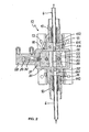
- Fig. 2 shows a cross-section of an interim storage,
- Fig. 3 shows a cross-section of the interim storage in a plane perpendicular to the cross-section of Fig. 2.
- Fig. 1 shows a
processing apparatus 1 intended for processing self-piercing rivets. Self-piercing rivets serve to connect sheet metal parts. They are pressed by a ram with great force from one side into the stacked metal sheets, the sheets being supported on a die forming an abutment. For this purpose, theprocessing apparatus 1 comprises a C-shaped bow 2, bearing a die 3 at one end and ahousing 4 at the opposed end, in which a ram movable against the die 3 and a device for driving the ram are arranged. To supply self-piercing rivets, there is aloading device 5 on theprocessing apparatus 1, to which self-piercing rivets placed in readiness by asupply unit 7 are supplied by way of apassage 6. Thepassage 6 consists in part of a yielding tube of synthetic material, in some applications bridging a distance of several meters between thesupply unit 7 and theprocessing unit 1. - The
supply unit 7 comprises twosupply containers 8, 9, serving to store two different self-piercing rivets A, B, differing from each other in length for example. Acontrollable switch 10 on thesupply unit 7 makes sure that in each instance the conveyed self-piercing rivet A or B, as the case may be, is supplied to thepassage 6. Alternatively, two separate supply units may be provided, whose exits are connected to the controlledswitch 10. - In the vicinity of the
loading device 5, there is aninterim reservoir 12 in thepassage 6, fastened to thehousing 4 of theprocessing unit 1. As may be seen in Figs. 2 and 3, theinterim reservoir 12 comprises astorage housing 13 havingconnection openings passage 6. Theconnection openings passage segments fastening segments fastening sleeves sleeve 16, the tube ofpassage 6 is fastened to thestorage housing 13. Thefastening sleeve 17 fastens the segment ofpassage 6 leading to theloading device 5, provided with a means of length equalization, for example a telescoping tube, if theloading device 5 is movable relative to theinterim reservoir 12. - The
storage housing 13 has a central prism-shapedrecess 18 with mutuallyopposed walls 19, 20, into which theconnection openings recess 18 is closed on top by alid 21. In therecess 18, a prism-shapedchamber housing 22 is arranged, movable to and fro in lengthwise direction of thewalls 19, 20 between two positions. Thechamber housing 22 contains twostorage chambers passage 6 and completely penetrating thechamber housing 22. Thestorage chambers chamber housing 22 shown in Fig. 2, thestorage chamber 23 is aligned with thepassage segments junction openings storage chamber 24 in the other position. The openings of thestorage chambers wall 19 form entrance openings, and the openings of thestorage chambers storage chambers latch 25 projecting at one end into theparticular storage chamber storage chamber spring 26. Thelatches 25 are so arranged that they permit a motion of a self-piercing rivet in the direction of the outlet openings and block it in the opposed direction. In the neighborhood of the outlet openings, eachstorage chamber sensor 27 whose cable passes out through a slit in thelid 21. With the aid of thesensors 27, the presence of self-piercing rivets in thestorage chambers - The motion of the
chamber housing 22 is effected by a double-action pneumatic cylinder 28 fastened to thestorage housing 13 whosepiston 29 is connected to thechamber housing 22 by apiston rod 30. The two positions of thechamber housing 22 are defined bytransverse walls reservoir housing 13, against which thechamber housing 22 strikes in each instance. - The
intermediate reservoir 12 comprises a shut-offslide 33 actuable by means of a double-action pneumatic cylinder 34. The shut-offslide 33 is arranged in an opening leading laterally into apassage segment 151 and, in the locking position shown in Fig. 3, projects into thepassage segment 151. In the open position, the lockingslide 33 is completely retracted from thepassage segment 151, so that a self-piercing rivet can pass thepassage segment 151 without hindrance. - In the bottom of the
passage segment 141, anozzle 35 configured in thereservoir housing 13 opens, in communication with anipple 16 for connection of a blown air line. Thenozzle opening 35 is inclined in the direction of conveyance, so that a blown jet of air exiting from it is directed into the entrance opening of the particularconnected reservoir chamber - In the following, the mode of operation of the supply device and the intermediate reservoir will be described in more detail.
- On commencement of operation, first the
sensors 27 are used to inquire whether self-piercing rivets are present in thestorage chambers storage chambers slide 23 is moved into the closing position, and thechamber housing 22 into the desired position for loading a rivet A, in which position for example thestorage chamber 23 is in connection with thejunction openings supply unit 7 is prompted to perform a first conveyance step for the self-piercing rivet A. Thesupply unit 7 individuates a rivet A, guides it through theswitch 10 into thepassage 6, and drives it with blown air into the connectedstorage chamber 23, where rivet A, after it has passed thelatch 25, is held back at the outlet opening of thestorage chamber 23 by theclosing slide 33. The presence of the rivet A is detected by thesensor 27 and communicated to the control. This terminates the operation, and initiates the loading of thestorage chamber 24 with a self-piercing rivet B. Thechamber housing 22 is moved for this purpose into the second position, in which thestorage chamber 24 is in communication with thejunction opening 14. Then the first step is repeated as described with a self-piercing rivet B. - After both
storage chambers sensors 27, control can initiate a cycle of operations. Process control then instructs supply control as to which self-piercing rivet variant, A or B, is to be supplied. If it is self-piercing rivet B, then no displacement of thechamber housing 22 is required, since thestorage chamber 24 containing self-piercing rivet B is in junction position. If a rivet A is to be supplied, then thechamber housing 22 is moved into the other position. Execution of the second step with rivet B merely runs theslide 33 into open position, and supply of blown air by thenozzle opening 35 puts the rivet B through thejunction opening 15 and thepassage 6 connected thereto to the loading device. After a short time interval X, at which the self-piercing rivet B will in any case be located in the loading device, the supply of blown air to thenozzle opening 35 shuts off again, and theslide 33 is run back into the closed position. At the same time, likewise time-controlled, the operation of the processing apparatus is started. - After completion of Step 2, slide 33 and
chamber housing 22 hold their position while the self-piercing rivet B, now absent instorage chamber 24, signals to control that in a renewed first step, a rivet B is again to be loaded in thestorage chamber 24. Thus the first step is to be repeated at once as described above with a new rivet B, so that before completion of the processing step, bothstorage chambers - The device described permits a reliable delivery of self-piercing rivets of different lengths into the loading device of a processor, and by dividing the delivery into two independent steps, provides for a short cycle and correspondingly high operating speed of the processor.
Claims (21)
- Method of supplying at least connecting elements to a processing unit, in which the connecting elements are placed in readiness by a supply unit and individually conveyed by a passage to a loading device arranged on the processing unit, said conveyance of the connecting elements taking place in two separate steps, a first step in which the connecting elements are individually conveyed into a intermediate reservoir arranged near the loading means, and a second step in which an individual connecting element in each instance is conveyed from the intermediate reservoir into the loading device of the processing system.
- Method according to claim 1, characterized in that at least two different connecting elements are supplied to the intermediate reservoir and accepted by the latter, and of the ones picked up by the intermediate reservoir, at least two different connecting elements intended for the second step are selected.
- Method according to either of claims 1 and 2, characterized in that the initiation of the first step takes place in response to the full condition of the intermediate reservoir.
- Method according to any of the preceding claims, characterized in that upon withdrawal of a connecting element from the intermediate reservoir by initiation of a second step, a first step is initiated to supply a new connecting element of the type withdrawn.
- Method according to any of the preceding claims, characterized in that the initiation of the second step takes place in response to the processing step to be executed by the processing unit.
- Method according to any of the preceding claims, characterized in that a processing step of the processor is initiated in response to the initiation of a second step with time delay.
- Method according to any of the preceding claims, characterized in that the conveyance of the individual connecting elements to the intermediate reservoir and from the intermediate reservoir to the processing unit is effected pneumatically.
- Method according to any of the preceding claims, characterized in that the state of fill of the intermediate reservoir is monitored by sensors.
- Device for supplying connecting elements to a processing unit (1) including a supply unit (7) by which connecting elements are placed in readiness individually, a passage (6) connecting the supply unit (7) to a loading device (5) arranged on a processing unit (1), and an intermediate reservoir (12) preceding the loading device (5) arranged to accommodate the connecting elements supplied by way of the passage and having at least two storage chambers (23, 24) each having an entrance opening and an exit opening, the segment of the passage (6) leading to the supply unit (7) being connectable with the segment of the passage (6) leading to the loading device (5) and either one of the exit openings of the storage chambers (23, 24).
- Device according to the preceding claim, characterized in that the interim reservoir (12) is configured to accept at least two different connecting elements.
- Device according to either of claims 9 and 10, characterized in that the entrance opening and the exit opening of a storage chamber (23, 24) are simultaneously connectable to the particular associated segment of the passage, the exit opening being closable by a controllable barrier (33).
- Device according to any of claims 9 to 11, characterized in that the storage chambers (23, 24) are arranged side-by-side in a chamber housing (22), the entrance openings and the exit openings being located on opposed sides of the chamber housing (22) and the chamber housing (22) being movable to and fro between two positions in a housing (13) of the interim reservoir (12), a first chamber (23) of the interim reservoir being connected to the junction openings (14, 15) for the passage (6) in the first position and a second chamber (24) in the second position.
- Device according to any of claims 9 to 12, characterized in that the chamber housing is movable by means of a double-action pneumatic cylinder.
- Device according to any of claims 9 to 13, characterized in that the entrance opening and the exit opening of a storage chamber (23 or 24) are connectable simultaneously to the segment of the passage (6) associated in each instance.
- Device according to any of claims 9 to 14, characterized in that the exit opening (15) is closable by a controllable barrier (33).
- Device according to claim 15, characterized in that the barrier (33) is actuable by a double-action pneumatic cylinder (34).
- Device according to any of claims 9 to 16, characterized in that the chamber housing (22) is configured as a prism-shaped slide movable lengthwise in a prism-shaped recess (18) in the housing of the interim reservoir (12) and penetrated transverse to its direction of motion by the storage chambers (23, 24).
- Device according to any of claims 9 to 17, characterized in that in the storage chambers (23, 24) barrier latches (25) are arranged behind the entrance openings in the direction of conveyance, permitting a motion of the connecting elements in the direction of advancement and barring it in the opposed direction.
- Device according to any of claims 9 to 18, characterized in that in the housing (13) of the intermediate reservoir (12), a nozzle opening into the passage for supply of blown air is provided and so arranged that a jet of blown air emerging from the nozzle is directed into the entrance opening of the particular storage chamber (23 or 24) connected to the passage.
- Device according to any of claims 9 to 19, characterized in that sensors are arranged on the storage chambers (23, 24) whose signals serve to control the supply of connecting elements and individual advancing steps.
- Device according to any of claims 9 to 20, characterized in that sensors are arranged on the supply unit, detecting when a connecting element leaves the supply unit (7).
Applications Claiming Priority (1)
| Application Number | Priority Date | Filing Date | Title |
|---|---|---|---|
| DE102005041534A DE102005041534A1 (en) | 2005-08-31 | 2005-08-31 | Supplying connecting elements, e.g. rivets or screws, to processing apparatus, involves two-stage conveyance via intermediate reservoir, allowing rapid, reliable interchange of different types of elements |
Publications (2)
| Publication Number | Publication Date |
|---|---|
| EP1759785A1 true EP1759785A1 (en) | 2007-03-07 |
| EP1759785B1 EP1759785B1 (en) | 2008-12-17 |
Family
ID=37510829
Family Applications (1)
| Application Number | Title | Priority Date | Filing Date |
|---|---|---|---|
| EP06017725A Ceased EP1759785B1 (en) | 2005-08-31 | 2006-08-25 | Method and device for supply of connecting elements to a processing apparatus |
Country Status (4)
| Country | Link |
|---|---|
| US (3) | US8015686B2 (en) |
| EP (1) | EP1759785B1 (en) |
| JP (1) | JP2007061909A (en) |
| DE (2) | DE102005041534A1 (en) |
Cited By (1)
| Publication number | Priority date | Publication date | Assignee | Title |
|---|---|---|---|---|
| CN112170767A (en) * | 2020-09-18 | 2021-01-05 | 山东大学 | A rivet feeding device and method |
Families Citing this family (24)
| Publication number | Priority date | Publication date | Assignee | Title |
|---|---|---|---|---|
| DE102005041534A1 (en) * | 2005-08-31 | 2007-03-01 | Newfrey Llc, Newark | Supplying connecting elements, e.g. rivets or screws, to processing apparatus, involves two-stage conveyance via intermediate reservoir, allowing rapid, reliable interchange of different types of elements |
| JP2010036214A (en) * | 2008-08-05 | 2010-02-18 | Nippon Pop Rivets & Fasteners Ltd | Self-piercing rivet setting machine |
| DE102008051489B4 (en) * | 2008-10-13 | 2021-07-01 | Böllhoff Verbindungstechnik GmbH | Setting tool with a magazine and a supply module for joining elements |
| DE102009024433A1 (en) * | 2009-06-05 | 2010-12-09 | Newfrey Llc, Newark | Separating slide for a device for feeding a connecting element |
| DE102009049616B4 (en) * | 2009-10-16 | 2019-05-09 | Böllhoff Verbindungstechnik GmbH | Setting tool, feeding module of the setting device and joining method for connecting at least two components |
| DE102012212502B4 (en) | 2012-04-16 | 2016-01-14 | Magna Steyr Fahrzeugtechnik Ag & Co Kg | Nietweiche for more than two different types of loose rivets |
| JP5809597B2 (en) * | 2012-05-08 | 2015-11-11 | 本田技研工業株式会社 | Nut supply system |
| US9027220B2 (en) * | 2012-08-07 | 2015-05-12 | Newfrey Llc | Rivet setting machine |
| DE102013000799B4 (en) * | 2013-01-17 | 2015-05-28 | Audi Ag | Device for feeding connecting elements to a processing device |
| EP3052267B1 (en) * | 2013-10-04 | 2023-06-07 | Structural Services, Inc. | Method for automatically welding studs on a surface of a beam |
| DE102013019519A1 (en) * | 2013-11-22 | 2015-05-28 | Tox Pressotechnik Gmbh & Co. Kg | "Device for attaching a joining element to a component section and tool" |
| DE102013226578A1 (en) * | 2013-12-19 | 2015-06-25 | Hauni Maschinenbau Ag | Machine arrangement and method for controlling a machine arrangement of the tobacco processing industry |
| DE102014119189A1 (en) * | 2014-12-19 | 2016-06-23 | Newfrey Llc | Fügeelementzuführvorrichtung |
| CN104668427B (en) * | 2014-12-31 | 2017-01-25 | 大连运明自动化技术有限公司 | High-speed intelligent distributing and feeding equipment of rivets |
| JP6647915B2 (en) * | 2016-02-29 | 2020-02-14 | パナソニックホームズ株式会社 | Piercing nut fixing device |
| DE102016112732A1 (en) | 2016-07-12 | 2018-01-18 | Böllhoff Verbindungstechnik GmbH | Non-variable path element switch and feed method |
| DE102017101705A1 (en) * | 2017-01-30 | 2018-08-02 | Newfrey Llc | Joining device, loading station, feeding arrangement and method for loading a magazine |
| US10675776B2 (en) * | 2017-06-06 | 2020-06-09 | Alliance Automation, Llc | Pallet assembly system |
| GB2569127A (en) | 2017-12-05 | 2019-06-12 | Atlas Copco Ias Uk Ltd | Nose arrangements for fastener setting machines, and related methods |
| GB2569122A (en) | 2017-12-05 | 2019-06-12 | Atlas Copco Ias Uk Ltd | Fastener handling devices for fastener setting machines, and related methods |
| GB2569126A (en) | 2017-12-05 | 2019-06-12 | Atlas Copco Ias Uk Ltd | Fastener magazines, and related supply systems and methods |
| CN110640028B (en) * | 2018-06-26 | 2024-10-18 | 北京长征火箭装备科技有限公司 | Automatic feeding riveting device and riveting method thereof |
| DE102018210473B4 (en) | 2018-06-27 | 2020-06-04 | Audi Ag | Compact separator |
| EP4616974A1 (en) * | 2020-05-06 | 2025-09-17 | Newfrey LLC | Fastening device, fastening device system and method for feeding fasteners |
Citations (7)
| Publication number | Priority date | Publication date | Assignee | Title |
|---|---|---|---|---|
| US4220275A (en) * | 1978-07-31 | 1980-09-02 | The Boeing Company | Fastener selection system |
| FR2662622A1 (en) * | 1990-06-05 | 1991-12-06 | Garonne Ets Auriol & Cie | Device for selecting and dispensing components such as rivets |
| EP0511093A1 (en) * | 1991-04-25 | 1992-10-28 | Etablissements SAINT - CHAMOND - GRANAT S.A. | Method and device for conditioning and distributing small cylindrical parts |
| EP0922538A2 (en) * | 1997-11-06 | 1999-06-16 | Emhart Inc. | Conveyor for elongate components designed with a head and shank |
| WO2000007751A1 (en) * | 1998-08-03 | 2000-02-17 | Henrob Ltd. | Improvements in or relating to fastening machines |
| EP1116678A1 (en) * | 2000-01-11 | 2001-07-18 | Peter Schindler | Handlings method for transferring a workpiece by keeping it into an exact orientation |
| DE10064241A1 (en) * | 2000-12-22 | 2002-07-04 | Strama Maschb Gmbh & Co Kg | Rivet feed device, for riveting machine, has rivet separator and issuer with pusher having rivet receiving aperture |
Family Cites Families (129)
| Publication number | Priority date | Publication date | Assignee | Title |
|---|---|---|---|---|
| US1859081A (en) | 1929-05-04 | 1932-05-17 | Elsner Heinrich | Riveting machine |
| US2216403A (en) | 1938-05-30 | 1940-10-01 | Frankfurter Maschb Ag | Drilling and riveting machine |
| DE744513C (en) | 1939-05-25 | 1944-01-18 | Messerschmitt Boelkow Blohm | Rivet loading device for rivet sorting devices on riveting machines |
| US2330052A (en) | 1942-12-10 | 1943-09-21 | Edgar G Henry | Portable fastener self-feeding tool |
| US2493868A (en) | 1943-10-26 | 1950-01-10 | Curtiss Wright Corp | Air gun rivet feed |
| US2544165A (en) | 1948-06-05 | 1951-03-06 | Air A Feed Equipment Inc | Power-operated semiautomatic screw driver |
| US2662626A (en) | 1950-02-17 | 1953-12-15 | Graham Mfg Corp | Orienting device |
| US2755538A (en) | 1952-01-05 | 1956-07-24 | Hoover Co | Commutator assembling machine |
| US2706504A (en) | 1952-09-04 | 1955-04-19 | Frank Manton | Power operated screwdriver with screw delivering means |
| FR1230342A (en) | 1959-07-18 | 1960-09-15 | Riveter-punching machine | |
| US3279045A (en) | 1964-08-03 | 1966-10-18 | Paul H Dixon | Assembling mechanism |
| US3289884A (en) | 1964-09-29 | 1966-12-06 | Adolph V Klancnik | Vibratory hopper with attached article guide means positionable adjacent a vertical magazine means |
| US3339799A (en) | 1965-09-07 | 1967-09-05 | Gregory Ind Inc | Fastener feed assembly including fastener size adjusting means |
| US3561641A (en) | 1968-12-19 | 1971-02-09 | Eltec Inc | Fastener supply device |
| US3623208A (en) | 1969-09-23 | 1971-11-30 | Hofmann Maschf Dionys | Method and apparatus for automatic balancing of motor vehicle wheels |
| US3750257A (en) | 1971-12-30 | 1973-08-07 | Kaynar Mfg Co | Systematized apparatus for driving fasteners |
| US3789490A (en) | 1972-02-17 | 1974-02-05 | Omark Industries Inc | Stud storage system |
| DE2403904A1 (en) | 1973-01-30 | 1974-08-08 | Paterex Ltd | WORKPIECE FEEDING DEVICE |
| CH563841A5 (en) | 1973-04-12 | 1975-07-15 | Lecureux Bernard | Automatic item feed to hand tool tip - involves moving lever with suction passage bringing items to tip held by suction only |
| US4005519A (en) | 1975-05-28 | 1977-02-01 | Marson Fastener Corporation | Apparatus for setting blind rivets |
| US4047281A (en) | 1975-05-28 | 1977-09-13 | Marson Corporation | Method of setting blind rivets |
| US4075748A (en) | 1977-01-28 | 1978-02-28 | Eaton Corporation | Fastener emplacement mechanism |
| JPS5645337A (en) | 1979-09-11 | 1981-04-25 | Hitachi Ltd | Feeding and assembling device for parts |
| JPS6018263Y2 (en) | 1979-09-28 | 1985-06-03 | 有限会社新城製作所 | Shoot hose connection device for automatic pierced nut assembly machine |
| US4765057A (en) | 1980-02-02 | 1988-08-23 | Multifastener Corporation | Self-attaching fastener, panel assembly and installation apparatus |
| US4555838A (en) | 1983-03-28 | 1985-12-03 | Multifastener Corp. | Method of installing self-attaching fasteners |
| US4633560A (en) | 1980-02-02 | 1987-01-06 | Multifastener Corporation | Self-attaching fastener, die set |
| USRE35619E (en) | 1981-01-28 | 1997-10-07 | Multifastener Corporation | Installation apparatus for installing self-attaching fasteners |
| JPS57156174U (en) | 1981-03-25 | 1982-10-01 | ||
| US4463888A (en) | 1981-04-22 | 1984-08-07 | Duo-Fast Corporation | Fastener driving tool |
| DE3222557C2 (en) * | 1982-06-16 | 1985-11-28 | ARO GmbH, 7024 Filderstadt | Separation device for screwdrivers, riveting machines, insertion machines or the like. |
| JPS5997862A (en) | 1982-11-24 | 1984-06-05 | 株式会社日立製作所 | Part feeder |
| US4620656A (en) | 1983-04-11 | 1986-11-04 | Herbert L. Engineering Corp. | Automatic rivet-feeding system for reliable delivery of plural rivet sizes |
| JPS6062429A (en) | 1983-09-13 | 1985-04-10 | Nissan Motor Co Ltd | Method and device for assembling parts |
| CA1255880A (en) | 1983-12-21 | 1989-06-20 | Rudolf R.M. Muller | Self-attaching fastener, method of installation and installation apparatus |
| US4729163A (en) | 1983-12-21 | 1988-03-08 | Multifastener Corporation | Die set assembly for attaching a fastener |
| JPS60216947A (en) | 1984-04-13 | 1985-10-30 | Hitachi Ltd | Device for supplying blind rivet |
| JPS60182288U (en) | 1984-05-16 | 1985-12-03 | 本田技研工業株式会社 | Vehicle door tightening device |
| CA1260174A (en) * | 1984-06-29 | 1989-09-26 | Kureha Chemical Ind Co Ltd | Para-phenylene sulfide, block copolymers, process for the production of the same and use thereof |
| US4625903A (en) | 1984-07-03 | 1986-12-02 | Sencorp | Multiple impact fastener driving tool |
| JPS61109644U (en) | 1984-12-24 | 1986-07-11 | ||
| JPS61109646U (en) | 1984-12-24 | 1986-07-11 | ||
| US4604889A (en) | 1984-12-27 | 1986-08-12 | Huck Manufacturing Company | Automated installation tool for blind fasteners |
| SE447552B (en) | 1985-04-09 | 1986-11-24 | Asea Ab | PROCEDURE AND INSTALLATION FOR MOUNTING NUTS IN A WORK PIECE |
| US4773156A (en) | 1985-09-18 | 1988-09-27 | Toyoda Gosei Co., Ltd. | Apparatus for securing parts |
| US4801043A (en) | 1985-11-18 | 1989-01-31 | Cindric Emil J | Parts orientor & method |
| US4630460A (en) | 1986-02-14 | 1986-12-23 | Usm Corporation | Fastener-setting tool |
| US4782588A (en) | 1986-11-19 | 1988-11-08 | Ruvo Automation Corp. | Door hinge applicator |
| US4715114A (en) | 1986-12-08 | 1987-12-29 | Tachi-S Co., Ltd. | Tension spring takeout device in an automatic tension spring mounting apparatus |
| US4819856A (en) | 1986-12-30 | 1989-04-11 | Gemcor Engineering Corp. | Method and apparatus for inserting fasteners |
| JPS6451234A (en) * | 1987-08-18 | 1989-02-27 | Mazda Motor | Parts feeder |
| US4852376A (en) | 1987-10-05 | 1989-08-01 | Huck Manufacturing Company | Lockbolt installation tool with cartridge feed |
| US4815343A (en) | 1987-11-05 | 1989-03-28 | United Container Machinery Group, Inc. | Robotic die mounting mechanism and method |
| US4885836A (en) | 1988-04-19 | 1989-12-12 | Imta | Riveting process and apparatus |
| US4901431A (en) | 1988-06-06 | 1990-02-20 | Textron Inc. | Powered fastener installation apparatus |
| GB2232110A (en) | 1989-05-26 | 1990-12-05 | Avdel Systems Ltd | Fastener installation apparatus |
| JP2678383B2 (en) | 1989-05-30 | 1997-11-17 | 信越半導体 株式会社 | Device for single crystal |
| US5201892A (en) | 1989-06-30 | 1993-04-13 | Ltv Areospace And Defense Company | Rivet orientating device |
| US4960360A (en) | 1989-07-19 | 1990-10-02 | Grumman Aerospace Corporation | Rivet orientation device and method |
| US5260734A (en) * | 1989-11-30 | 1993-11-09 | Asahi Kogaku Kogyo Kabushiki Kaisha | Determining a direction in which an eye gazes |
| DE9016493U1 (en) | 1990-12-05 | 1991-03-14 | Paslode GmbH, 6236 Eschborn | Nail driver |
| US5231747A (en) | 1990-12-21 | 1993-08-03 | The Boeing Company | Drill/rivet device |
| US5259104A (en) | 1990-12-21 | 1993-11-09 | The Boeing Company | Rivet recovery method |
| US5216819A (en) | 1990-12-21 | 1993-06-08 | The Boeing Company | Method of detecting long and short rivets |
| US5193717A (en) | 1991-04-30 | 1993-03-16 | Electroimpact, Inc. | Fastener feed system |
| JP3159474B2 (en) | 1991-06-20 | 2001-04-23 | 国際計測器株式会社 | Tire wheel balance weight mounting device |
| US5193729A (en) | 1991-09-26 | 1993-03-16 | Illinois Tool Works Inc. | Fastener-driving tool assembly with improved fastener-loading features |
| JP2950662B2 (en) | 1991-10-11 | 1999-09-20 | 東京マルチファスナー株式会社 | Parts continuous supply device |
| US5236341A (en) | 1992-03-09 | 1993-08-17 | Teledyne Ryan Aeronautical, Div. Of Teledyne Ind., Inc. | Automatic blind rivet feeding system attachment |
| ATE157916T1 (en) | 1992-04-21 | 1997-09-15 | Ariel Ind Plc | FEED PIPE FOR FASTENING ELEMENTS |
| US5360137A (en) | 1992-07-17 | 1994-11-01 | Yugenkaisha Shinjo Seisakusho | Row feeder for distributing nuts |
| US5565242A (en) * | 1992-09-21 | 1996-10-15 | The Boeing Company | Lubricant applications to a hole |
| GB9226517D0 (en) | 1992-12-19 | 1993-02-10 | Henrob Ltd | Improvements in or relating to sefl-piercing riveting |
| DE4244403A1 (en) | 1992-12-29 | 1994-07-07 | Deutsche Aerospace Airbus | Automatic riveting machine |
| WO1994015736A1 (en) | 1993-01-07 | 1994-07-21 | Henrob Ltd. | Improved fastening tools |
| IT1272121B (en) * | 1993-03-22 | 1997-06-11 | Bears Srl | SYSTEM FOR THE SELECTION AND AUTOMATIC FEEDING OF PRE-ORIENTED RIVETS FOR RIVETING MACHINES |
| DE4310953A1 (en) | 1993-04-02 | 1994-10-13 | Wolfgang Dipl Ing Luckhardt | Press-in device for pressing in parts to be joined |
| DE4400350C2 (en) | 1994-01-08 | 1997-08-07 | Bettermann Obo Ohg | Stud welding device |
| JP2824735B2 (en) | 1994-04-02 | 1998-11-18 | 好高 青山 | Parts supply device |
| AUPM507094A0 (en) | 1994-04-14 | 1994-05-05 | Henrob Ltd | Improved fastening machine |
| FR2720963B1 (en) | 1994-06-13 | 1996-09-06 | Haute Garonne Ateliers | Device for distributing single pieces and device for storing these pieces. |
| JPH08229847A (en) | 1995-02-28 | 1996-09-10 | Max Co Ltd | Attachment for box nailing machine |
| US5640758A (en) | 1995-04-12 | 1997-06-24 | Emhart Inc. | Component feeder with reciprocal and rotatable magazine |
| US5579975A (en) | 1995-04-19 | 1996-12-03 | Senco Products, Inc. | Fastener driving tool for locating a pre-existing through hole in a workpiece and driving a fastener therethrough |
| US5758798A (en) | 1996-07-19 | 1998-06-02 | Nylok Fastener Corporation | Parts orientor and method |
| DE19731344B4 (en) | 1997-06-07 | 2006-09-14 | Dieter Schmidt | System for feeding fasteners to a punch head |
| US6276050B1 (en) | 1998-07-20 | 2001-08-21 | Emhart Inc. | Riveting system and process for forming a riveted joint |
| US5897045A (en) | 1997-09-12 | 1999-04-27 | Illinois Tool Works Inc. | Fastener dispensing apparatus for stand-up fastener driving tool and method therefor |
| DE19756798A1 (en) | 1997-12-19 | 1999-06-24 | Schmidt Dieter Maschbau | Connector components supply system for presses etc. |
| WO1999034953A1 (en) * | 1998-01-07 | 1999-07-15 | Fabristeel Products, Inc. | A fastener installation head having a pivoting fastener drive assembly |
| JP4028926B2 (en) | 1998-02-12 | 2008-01-09 | 株式会社シマノ | Fishing rod and method of manufacturing the rod |
| US6796454B1 (en) | 1998-08-03 | 2004-09-28 | Henrob Limited | Fastening machines |
| US6347449B1 (en) | 1998-10-21 | 2002-02-19 | Emhart Inc. | Modular portable rivet setting tool |
| US6264063B1 (en) * | 1998-10-23 | 2001-07-24 | Vought Aircraft Industries, Inc. | Orientation maintained fastener delivery system and method |
| US6196414B1 (en) * | 1998-10-23 | 2001-03-06 | Vought Aircraft Industries, Inc. | Fastener injector system and method |
| DE19924310B4 (en) | 1999-05-27 | 2007-11-22 | Böllhoff GmbH | Hydraulic drive device for a joining tool |
| US6588576B1 (en) * | 1999-06-14 | 2003-07-08 | Newfrey Llc | Methods of and device for feeding fastening elements |
| US6388224B1 (en) | 1999-12-28 | 2002-05-14 | Abb T&D Technology Ltd. | Systems for robotic stud arc welding without ferrule |
| US6789309B2 (en) | 2000-02-22 | 2004-09-14 | Newfrey Llc | Self-piercing robotic rivet setting system |
| JP2001353549A (en) | 2000-06-14 | 2001-12-25 | Nippon Pop Rivets & Fasteners Ltd | Automatic drilling type riveting machine |
| DE10031073B4 (en) * | 2000-06-30 | 2016-11-24 | Gustav Klauke Gmbh | Method of riveting |
| FR2823065B1 (en) * | 2001-04-04 | 2004-08-13 | Chevillot Sa | EAR LABEL FOR MARKING ANIMALS WITH ORGANIC MATTER COLLECTION SYSTEM |
| DE20106207U1 (en) | 2001-04-09 | 2001-06-21 | Böllhoff GmbH, 33649 Bielefeld | Drive device for a press tool |
| US6942134B2 (en) | 2001-04-17 | 2005-09-13 | Newfrey Llc | Self-piercing rivet setting machine |
| US6910263B2 (en) | 2001-12-25 | 2005-06-28 | Newfrey Llc | Self-piercing rivet setting apparatus and system |
| DE10223154A1 (en) | 2002-05-16 | 2003-11-27 | Newfrey Llc | Joining system head, joining system and method for feeding and joining elements |
| DE10223147A1 (en) | 2002-05-16 | 2003-11-27 | Newfrey Llc | Joining system head, joining system and method for feeding and joining elements |
| GB2392716B (en) | 2002-09-09 | 2005-09-07 | Emhart Llc | Self-piercing blind fastener |
| US6892921B2 (en) * | 2002-10-30 | 2005-05-17 | Porter-Cable Corporation | Apparatus and method to indicate required compressor pressure for use with pneumatic tool device |
| US20040111876A1 (en) * | 2002-12-13 | 2004-06-17 | Andrew Cheng | Reworking device for removing electrical elements mounted on motherboard |
| US6986450B2 (en) * | 2003-04-30 | 2006-01-17 | Henrob Limited | Fastener insertion apparatus |
| DE102005006795A1 (en) * | 2005-02-14 | 2006-08-24 | Newfrey Llc, Newark | Method and device for feeding connecting elements to a processing device |
| DE102005041534A1 (en) * | 2005-08-31 | 2007-03-01 | Newfrey Llc, Newark | Supplying connecting elements, e.g. rivets or screws, to processing apparatus, involves two-stage conveyance via intermediate reservoir, allowing rapid, reliable interchange of different types of elements |
| GB0518696D0 (en) * | 2005-09-14 | 2005-10-19 | Henrob Ltd | Fastener feed method and apparatus |
| US8046898B2 (en) * | 2005-10-18 | 2011-11-01 | The Boeing Company | Fastener clearing systems and methods |
| US7832074B2 (en) * | 2006-05-25 | 2010-11-16 | Gm Global Technology Operations, Inc. | Method for installation of blind rivets |
| WO2009112804A2 (en) * | 2008-03-10 | 2009-09-17 | Henrob Limited | Die condition detection |
| GB0818401D0 (en) * | 2008-10-08 | 2008-11-12 | Henrob Ltd | Fastener feed method and apparatus |
| DE102009030103A1 (en) * | 2009-06-22 | 2010-12-23 | Tox Pressotechnik Gmbh & Co. Kg | Device for providing fastening elements for a production tool and production tool |
| US20110131776A1 (en) * | 2009-12-04 | 2011-06-09 | Stoeger Lorenz | Automatic device for setting rivets |
| EP2637812B1 (en) * | 2010-11-10 | 2018-02-21 | Henrob Limited | Riveting method |
| US8769788B2 (en) * | 2011-06-17 | 2014-07-08 | Btm Corporation | Rivet machine |
| US8769789B2 (en) * | 2011-06-17 | 2014-07-08 | Btm Corporation | Die for rivet machine |
| US8869365B2 (en) * | 2011-06-24 | 2014-10-28 | Btm Corporation | Rivet guide head |
| DE102012212502B4 (en) * | 2012-04-16 | 2016-01-14 | Magna Steyr Fahrzeugtechnik Ag & Co Kg | Nietweiche for more than two different types of loose rivets |
| DE102013000799B4 (en) * | 2013-01-17 | 2015-05-28 | Audi Ag | Device for feeding connecting elements to a processing device |
| CN105916625B (en) * | 2014-01-16 | 2020-04-21 | 阿特拉斯·科普柯 Ias (英国) 有限公司 | Install components |
| US9662754B2 (en) * | 2014-10-01 | 2017-05-30 | Honda Motor Co., Ltd. | Automatic fastener driving system, apparatus and method |
| DE102015111227A1 (en) * | 2015-07-10 | 2017-01-12 | Heiko Schmidt | processing pliers |
-
2005
- 2005-08-31 DE DE102005041534A patent/DE102005041534A1/en not_active Withdrawn
-
2006
- 2006-08-25 EP EP06017725A patent/EP1759785B1/en not_active Ceased
- 2006-08-25 DE DE602006004270T patent/DE602006004270D1/en active Active
- 2006-08-25 JP JP2006228990A patent/JP2007061909A/en active Pending
- 2006-08-25 US US11/510,856 patent/US8015686B2/en active Active
-
2011
- 2011-08-02 US US13/196,190 patent/US8973247B2/en not_active Expired - Fee Related
-
2015
- 2015-03-06 US US14/640,462 patent/US20150174711A1/en not_active Abandoned
Patent Citations (7)
| Publication number | Priority date | Publication date | Assignee | Title |
|---|---|---|---|---|
| US4220275A (en) * | 1978-07-31 | 1980-09-02 | The Boeing Company | Fastener selection system |
| FR2662622A1 (en) * | 1990-06-05 | 1991-12-06 | Garonne Ets Auriol & Cie | Device for selecting and dispensing components such as rivets |
| EP0511093A1 (en) * | 1991-04-25 | 1992-10-28 | Etablissements SAINT - CHAMOND - GRANAT S.A. | Method and device for conditioning and distributing small cylindrical parts |
| EP0922538A2 (en) * | 1997-11-06 | 1999-06-16 | Emhart Inc. | Conveyor for elongate components designed with a head and shank |
| WO2000007751A1 (en) * | 1998-08-03 | 2000-02-17 | Henrob Ltd. | Improvements in or relating to fastening machines |
| EP1116678A1 (en) * | 2000-01-11 | 2001-07-18 | Peter Schindler | Handlings method for transferring a workpiece by keeping it into an exact orientation |
| DE10064241A1 (en) * | 2000-12-22 | 2002-07-04 | Strama Maschb Gmbh & Co Kg | Rivet feed device, for riveting machine, has rivet separator and issuer with pusher having rivet receiving aperture |
Cited By (1)
| Publication number | Priority date | Publication date | Assignee | Title |
|---|---|---|---|---|
| CN112170767A (en) * | 2020-09-18 | 2021-01-05 | 山东大学 | A rivet feeding device and method |
Also Published As
| Publication number | Publication date |
|---|---|
| US20150174711A1 (en) | 2015-06-25 |
| DE602006004270D1 (en) | 2009-01-29 |
| US20110289763A1 (en) | 2011-12-01 |
| US20070049067A1 (en) | 2007-03-01 |
| DE102005041534A1 (en) | 2007-03-01 |
| US8973247B2 (en) | 2015-03-10 |
| US8015686B2 (en) | 2011-09-13 |
| JP2007061909A (en) | 2007-03-15 |
| EP1759785B1 (en) | 2008-12-17 |
Similar Documents
| Publication | Publication Date | Title |
|---|---|---|
| US8973247B2 (en) | Method and device for supply of connecting elements to a processing apparatus | |
| US20070289354A1 (en) | Method And Apparatus For Feeding Fasteners To A Processing Device | |
| US4790470A (en) | Fastener installation apparatus | |
| US6986450B2 (en) | Fastener insertion apparatus | |
| EP2308613B1 (en) | Fastener feed method and apparatus | |
| EP2640536B1 (en) | Method and apparatus for feeding joining elements | |
| EP2340135B1 (en) | Fastener feed method and apparatus | |
| CA2194145A1 (en) | Rivet feed device | |
| US4278184A (en) | Escapement mechanism for automatic fastener insert mechanisms | |
| US3658230A (en) | Automatic blind riveting machines | |
| DE69617298D1 (en) | riveter | |
| CZ317796A3 (en) | Equipment intended for use in a press for supply connecting elements and their fastening in workpieces by pressing | |
| EP0130076B1 (en) | Riveting machines | |
| US5065898A (en) | Apparatus for orienting and injecting fasteners | |
| US3828603A (en) | Riveting apparatus | |
| US5143572A (en) | Dowel shooting apparatus | |
| US5687613A (en) | Crimp connector applicator | |
| US3460664A (en) | Equipment for sorting grooved pins | |
| IL39631A (en) | Apparatus for setting blind tubular rivets including means for automatically supplying the rivets | |
| CN121604382A (en) | Feeding device for a coupling element, mounting tool with a feeding device, and associated feeding and mounting method | |
| US20060075618A1 (en) | Automatic nailing system |
Legal Events
| Date | Code | Title | Description |
|---|---|---|---|
| PUAI | Public reference made under article 153(3) epc to a published international application that has entered the european phase |
Free format text: ORIGINAL CODE: 0009012 |
|
| AK | Designated contracting states |
Kind code of ref document: A1 Designated state(s): AT BE BG CH CY CZ DE DK EE ES FI FR GB GR HU IE IS IT LI LT LU LV MC NL PL PT RO SE SI SK TR |
|
| AX | Request for extension of the european patent |
Extension state: AL BA HR MK YU |
|
| 17P | Request for examination filed |
Effective date: 20070712 |
|
| 17Q | First examination report despatched |
Effective date: 20070817 |
|
| AKX | Designation fees paid |
Designated state(s): DE |
|
| GRAP | Despatch of communication of intention to grant a patent |
Free format text: ORIGINAL CODE: EPIDOSNIGR1 |
|
| GRAS | Grant fee paid |
Free format text: ORIGINAL CODE: EPIDOSNIGR3 |
|
| GRAA | (expected) grant |
Free format text: ORIGINAL CODE: 0009210 |
|
| AK | Designated contracting states |
Kind code of ref document: B1 Designated state(s): DE |
|
| REF | Corresponds to: |
Ref document number: 602006004270 Country of ref document: DE Date of ref document: 20090129 Kind code of ref document: P |
|
| PLBI | Opposition filed |
Free format text: ORIGINAL CODE: 0009260 |
|
| PLAX | Notice of opposition and request to file observation + time limit sent |
Free format text: ORIGINAL CODE: EPIDOSNOBS2 |
|
| 26 | Opposition filed |
Opponent name: BOELLHOF VERBINDUNGSTECHNIK GMBH Effective date: 20090917 |
|
| PLBB | Reply of patent proprietor to notice(s) of opposition received |
Free format text: ORIGINAL CODE: EPIDOSNOBS3 |
|
| PLBP | Opposition withdrawn |
Free format text: ORIGINAL CODE: 0009264 |
|
| PLBD | Termination of opposition procedure: decision despatched |
Free format text: ORIGINAL CODE: EPIDOSNOPC1 |
|
| PLBM | Termination of opposition procedure: date of legal effect published |
Free format text: ORIGINAL CODE: 0009276 |
|
| STAA | Information on the status of an ep patent application or granted ep patent |
Free format text: STATUS: OPPOSITION PROCEDURE CLOSED |
|
| 27C | Opposition proceedings terminated |
Effective date: 20101220 |
|
| PGFP | Annual fee paid to national office [announced via postgrant information from national office to epo] |
Ref country code: DE Payment date: 20190813 Year of fee payment: 14 |
|
| REG | Reference to a national code |
Ref country code: DE Ref legal event code: R119 Ref document number: 602006004270 Country of ref document: DE |
|
| PG25 | Lapsed in a contracting state [announced via postgrant information from national office to epo] |
Ref country code: DE Free format text: LAPSE BECAUSE OF NON-PAYMENT OF DUE FEES Effective date: 20210302 |