EP1759263B1 - Laufwerkträger - Google Patents
Laufwerkträger Download PDFInfo
- Publication number
- EP1759263B1 EP1759263B1 EP05758789A EP05758789A EP1759263B1 EP 1759263 B1 EP1759263 B1 EP 1759263B1 EP 05758789 A EP05758789 A EP 05758789A EP 05758789 A EP05758789 A EP 05758789A EP 1759263 B1 EP1759263 B1 EP 1759263B1
- Authority
- EP
- European Patent Office
- Prior art keywords
- carrier
- receiving location
- drive
- drive carrier
- handle portion
- Prior art date
- Legal status (The legal status is an assumption and is not a legal conclusion. Google has not performed a legal analysis and makes no representation as to the accuracy of the status listed.)
- Expired - Lifetime
Links
Images


Classifications
-
- G—PHYSICS
- G11—INFORMATION STORAGE
- G11B—INFORMATION STORAGE BASED ON RELATIVE MOVEMENT BETWEEN RECORD CARRIER AND TRANSDUCER
- G11B33/00—Constructional parts, details or accessories not provided for in the other groups of this subclass
- G11B33/12—Disposition of constructional parts in the apparatus, e.g. of power supply, of modules
- G11B33/125—Disposition of constructional parts in the apparatus, e.g. of power supply, of modules the apparatus comprising a plurality of recording/reproducing devices, e.g. modular arrangements, arrays of disc drives
- G11B33/126—Arrangements for providing electrical connections, e.g. connectors, cables, switches
-
- G—PHYSICS
- G06—COMPUTING OR CALCULATING; COUNTING
- G06F—ELECTRIC DIGITAL DATA PROCESSING
- G06F1/00—Details not covered by groups G06F3/00 - G06F13/00 and G06F21/00
- G06F1/16—Constructional details or arrangements
- G06F1/18—Packaging or power distribution
- G06F1/183—Internal mounting support structures, e.g. for supporting printed circuit boards
- G06F1/184—Mounting of motherboards
-
- G—PHYSICS
- G06—COMPUTING OR CALCULATING; COUNTING
- G06F—ELECTRIC DIGITAL DATA PROCESSING
- G06F1/00—Details not covered by groups G06F3/00 - G06F13/00 and G06F21/00
- G06F1/16—Constructional details or arrangements
- G06F1/18—Packaging or power distribution
- G06F1/183—Internal mounting support structures, e.g. for supporting printed circuit boards
- G06F1/187—Mounting of fixed or removable disk drives
-
- G—PHYSICS
- G11—INFORMATION STORAGE
- G11B—INFORMATION STORAGE BASED ON RELATIVE MOVEMENT BETWEEN RECORD CARRIER AND TRANSDUCER
- G11B33/00—Constructional parts, details or accessories not provided for in the other groups of this subclass
- G11B33/12—Disposition of constructional parts in the apparatus, e.g. of power supply, of modules
- G11B33/125—Disposition of constructional parts in the apparatus, e.g. of power supply, of modules the apparatus comprising a plurality of recording/reproducing devices, e.g. modular arrangements, arrays of disc drives
- G11B33/127—Mounting arrangements of constructional parts onto a chassis
- G11B33/128—Mounting arrangements of constructional parts onto a chassis of the plurality of recording/reproducing devices, e.g. disk drives, onto a chassis
Definitions
- This invention relates to drive carriers for media drives. More specifically, this invention relates to drive carriers which are configured to receive a media drive, and which are also configured to be removably receivable in a receiving location of a computer system.
- Computer systems typically include one or more media drives such as a hard disk drives, CD ROM drives or DVD drives.
- One or more receiving locations can be included in the chassis of a computer for receiving these drives.
- the media drives can either be directly mounted within those receiving locations, or may be first received in a carrier, which is itself receivable in a receiving location.
- a media drive be configured as a field replaceable unit (FRU) and that it be hot-pluggable so as to reduce down time in the event that the media drive needs replacing. Accordingly, it is desirable that the media drive be quickly and easily installable within the chassis of a computer system, as well as quickly and easily removable. While it is known to provide drive carriers which allow a media drive to be slideably inserted into a receiving location, these drive carriers require a number of separate steps to be taken to insert and then secure the drive carrier in place. For example, it may be necessary to first push the drive carrier into the receiving location and then perform a separate operation to secure the drive carrier once it is in place.
- FRU field replaceable unit
- a first movement in a first direction may be required to insert the drive carrier into a receiving location and then a second, separate movement of a handle of the drive carrier in a direction different to the first direction (for example a pivotal motion) may be required to secure the drive carrier in the receiving location.
- Existing drive carriers also often fail to provide a user with feedback on insertion of the drive into a receiving location, whereby it is often not apparent whether the drive is correctly positioned/received.
- a media drive be provided with a degree of electromagnetic interference (EMI) protection. Protection against electrostatic discharge (ESD) is also desirable.
- EMI electromagnetic interference
- ESD electrostatic discharge
- features which protect against EMI and ESD often include metal protrusions which protrude from the drive carrier to press against a metallic feature of a receiving location such as a wall of the receiving location or a neighbouring media drive. These features can thus hinder easy insertion/removal of the media drive within/from the receiving location since sliding resistance against the insertion/removal is increased.
- the present invention aims to provide a drive carrier for a media drive which addresses at least some of the problems of existing drive carriers indicated above.
- US 6,227,630 describes a mounting for a computer accessory such as a hard disc drive that comprises a tray for accommodating the accessory which can be inserted into a mounting bay in the computer against a pair of springs.
- the tray carries a bezel member movable along the insertion path independently of the tray to latch or unlatch the tray in place, using latching members in association with latching tracks formed in the bezel by way of a push-push action.
- An embodiment of the invention can provide a drive carrier.
- the drive carrier is configured to receive a media drive and is also configured to be removably receivable in a receiving location of a computer system.
- the carrier includes a base portion, a handle portion and a latch mechanism for securing the carrier within the receiving location.
- the base portion and the handle portion are configured to co-operate to operate the latch mechanism on insertion and/or removal of the carrier from the receiving location, for inserting and/or removing the carrier from the receiving location and operating the latch mechanism with a single movement of the handle portion.
- the single movement is a linear movement in the direction of insertion/removal of the drive carrier from the receiving location.
- the handle portion is actuable to move between a first position and a second position relative to the base portion for operating the latch mechanism.
- the single movement of the handle portion includes actuating the handle between the first position and the second position.
- the latch mechanism can include a resilient latch portion and an aperture in the handle portion.
- the latch portion When the latch mechanism is in the deployed state, the latch portion can protrude through the aperture in the handle portion for engaging with a formation of a receiving location. Movement of the handle from the first position to the second position can cause the latch portion to be retracted through the aperture in the handle portion.
- the drive carrier can also include a plurality of electromagnetic interference (EMI) fingers.
- the fingers can be configured to occupy a deployed position in which they can abut a neighbouring drive carrier, media drive or inner wall of the receiving location, and a retracted position for reducing sliding resistance on insertion and/or removal of the drive carrier from the receiving location. Movement of the handle portion between the first position and the second position can move the EMI fingers between the deployed position and the retracted position, as well as operate the latch mechanism.
- EMI electromagnetic interference
- the drive carrier can be provided with one or more electrostatic discharge (ESD) fingers.
- ESD electrostatic discharge
- An embodiment of the invention can provide a drive carrier having a media drive received therein.
- An embodiment of the invention can provide a computer system which includes a receiving location and a drive carrier as set out above.
- a method of removing a media drive from a computer system can include providing a such a drive carrier.
- the drive carrier has the media drive received therein and is removably received within a receiving location of the computer system.
- the drive carrier includes a base portion, a handle portion and a latch mechanism for securing the carrier within the receiving location.
- the base portion and the handle portion are configured to co-operate to operate the latch mechanism on insertion and/or removal of the carrier from the receiving location, for inserting and/or removing the carrier from the receiving location and operating the latch mechanism with a single movement of the handle portion.
- the method also includes moving the handle to operate the latch mechanism and remove the carrier from the receiving location.
- the handle portion is moved relative to the base portion with a single, linear movement in the direction of removal of the drive carrier from the receiving location from a first position in which the latch mechanism is in a deployed state for securing the drive carrier within the receiving location, to a second position in which the latch mechanism is in a retracted state.
- a method of installing a media drive in a computer system can include providing such a drive carrier having the media drive received therein.
- the drive carrier includes a base portion, a handle portion and a latch mechanism for securing the carrier within the receiving location.
- the base portion and the handle portion are configured to co-operate to operate the latch mechanism on insertion and/or removal of the carrier from the receiving location, for inserting and/or removing the carrier from the receiving location and operating the latch mechanism with a single movement of the handle portion.
- the method also includes moving the handle to insert the carrier within the receiving location and to operate the latch mechanism.
- the handle portion is moved relative to the base portion with a single, linear movement in the direction of insertion of the drive carrier to the receiving location from a second position in which the latch mechanism is in a retracted state to a first position in which the latch mechanism is in a deployed state for securing the drive carrier within the receiving location.
- Figure 1 shows an example of a computer system 10.
- the computer system 10 includes a housing which has a front side 14, a rear side 26 and two opposing sides 12. For the purposes of clarity the top side of the housing is not shown in Figure 1 so as not to obscure the interior of the housing.
- the computer system 10 may also include a number of peripheral devices such as a monitor, a keyboard and a mouse - these are also omitted in Figure 1 .
- a number of components can be provided within the housing.
- a motherboard 20 which itself has a number of components 22 mounted thereon.
- a receiving location 24 for receiving a media drive within the housing. In this example, the receiving location 24 is accessible through an aperture in the rear side 26 of the housing.
- the receiving location may be accessible from another side of the housing (eg the front side 14).
- the rear side 26 can also include other features such as a power socket 18, a number of ports 16 and so forth.
- a media drive is received within a carrier, which is itself received within the receiving location 24.
- a handle portion 30 of the drive carrier is accessible at the aperture in the rear side 26.
- FIG 2 shows an example of a storage array 40 which may be incorporated as part of a larger computer system.
- the storage array 40 includes a housing 42 within which a number of drive carriers are received.
- the housing 42 includes a front face 44 through which the drive carriers may be inserted/removed.
- the storage array 40 shown in Figure 2 has four drive carriers received therein.
- Each drive carrier includes a handle portion 30, which is accessible through the front face 44 of the housing 42.
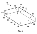
- Figure 3 shows an example of a media drive 50, which is receivable within a drive carrier.
- the media drive may, for example, be a hard disk drive such as a 2.5" serial attached SCSI (SAS) or serial ATA (SATA) hard disk drive.
- SAS serial attached SCSI
- SATA serial ATA
- the media drive 50 may be a CD ROM drive or DVD drive.
- the media drive has a front side 52, a rear side 58, two opposing sides 54, an upper side 57 and a lower side 56.
- the media drive can include a number of features 62 (eg screw holes) to facilitate mounting of the media drive 50 in a drive carrier.
- the media drive 50 can include a number of indicator lights for indicating a status of the drive e.g. an on/off state and/or whether the drive is presently being accessed. In this example, three indicator lights 60 are provided on the front side 52 of the media drive 50.
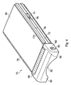
- the drive carrier 70 shown in Figures 4 to 8 includes a base portion 110 and a handle portion 30.
- a media drive 50 is received in the drive carrier 70 by mounting the media drive 50 directly onto the base portion 110. Attachments such as screws or bolts can be used to attach the media drive 50 to the base portion 110.
- the drive carrier 70 also includes a latch mechanism.
- the latch mechanism can include a resilient latch portion 80 located toward either side of the handle portion 30, and two apertures 82 through which each of the resilient latch portions 80 can protrude when in a deployed state.
- the deployed state is illustrated in Figure 4 , which shows one of the resilient latch portions 80 protruding through a corresponding aperture 82 in the handle portion 30.
- the base portion 110 and the handle portion 30 are configured to cooperate for operating the latch mechanism.
- the handle portion 30 can be actuated to move relative to the base portion 110 for operating the latch mechanism.
- the handle portion 30 can be moved linearly from a first position (shown in Figure 4 ) and second position (shown in Figure 5 ), whereby the resilient latch portions 80 engage with one side of their respective apertures 82, and are thereby caused to retract through those apertures 82 into a retracted position.
- the handle portion 30 can be provided with slides 72, which are received with guide rails 78 attached to the base portion 110.
- the slides 72 can be integrally formed with the remainder of the handle portion 30.
- the handle portion 30 may be constructed from, for example, a plastics material or from some other non-conductive material.
- the guide rails 78 may also be formed from a plastics material or some other non-conductive material. The materials used can be chosen to minimise sliding resistance (friction) between the slides 72 and the guide rails 78.
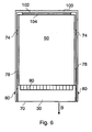
- FIGs 6 and 7 illustrate a receiving location 100 within which there is received a drive carrier 70 such as that illustrated in Figures 4 and 5 .
- the media drive 50 has a connector 104 provided on a rear surface thereof, for connecting with a connector 102 of the receiving location 100.
- the latch mechanism is shown in its deployed state. Accordingly, the handle portion 30 is in the first position relative to the base portion 110 as illustrated in Figure 4 .
- the resilient latch portions 80 of the latch mechanism protrude through the apertures 82 as illustrated in Figure 4 and engage with formations of the receiving location 100, for securing the drive carrier 70 within the receiving location 100.
- the formations with which the latch portions 80 engage are apertures located in the side walls of the receiving location 100.
- the resilient latch portions 80 protrude through the apertures of the receiving location and engage therewith.
- the apertures in this example are so positioned on the side walls of the receiving location 100 such that they align with the apertures 82 of the handle portion 30 when the handle portion is in the first position shown in Figure 4 .
- the example shown in Figure 2 includes apertures of this kind, which are visible on the sides of the housing 42.
- Figure 7 shows the drive carrier still received within the receiving location 100, but with the handle portion 30 in the second position.
- the resilient latch portions 80 are retracted through their respective apertures 82 in the handle portion 30; and accordingly are not visible in Figure 7 .
- the resilient latch portions 82 do not engage with the formations of the receiving location 100 and the drive carrier 70 is not secured within the receiving location 100.
- the drive carrier 70 can therefore be removed from the receiving location 100 by continuing to pull on the handle portion 30 in the direction shown by the arrow labelled B in Figure 6 to disengage the connectors 102 and 104 and withdraw the drive carrier 70 from the receiving location 100.
- the drive carrier 70 and/or the receiving location 100 can be provided with formations such as guide rails for guiding the drive carrier 70 as it is inserted and/or withdrawn from the receiving location 100.
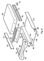
- the example of a drive carrier 70 shown in Figures 4 to 9 also includes a number of features to protect against electromagnetic interference (EMI) and electrostatic discharge (ESD).
- Attached to a front surface of the media drive 50 is an array of EMI fingers 90.
- the array 90 includes a plurality of fingers which are curved to protrude outwardly from the drive carrier 70 and engage with a neighbouring surface.
- the neighbouring surface may, for example, be a surface of a neighbouring drive carrier and/or media drive or a surface of a receiving location
- the handle portion 30 includes a ramp 92.
- the fingers of the array 90 occupy a retracted position in which they do not significantly protrude away from the drive carrier 70.
- the fingers may be flush with the upper surface of the received media drive 50. It is envisaged that when the drive carrier 70 is being inserted or removed from a receiving location 100, the handle portion 30 will be in the second position, whereby the protracted fingers of the EMI array 90 cannot scrape against a neighbouring surface, which would increase sliding resistance against movement of the drive carrier 70 within the receiving location 100 and potentially damage the neighbouring surface.
- the fingers of the EMI array 90 engage with the ramp 92 and are thereby urged outwards and away from the drive carrier 70. Accordingly, moving the handle portion 30 from the second position to the first position can actuate the fingers of the EMI array 90 into a deployed position for abutting against a neighbouring surface. In its deployed position, the EMI array 90 provides an effective EMI gasket for the media drive 50. Conversely, moving the handle portion 30 from the first position shown in Figure 4 to the second position shown in Figure 5 actuates the fingers of the EMI array 90 from the deployed position to a retracted position.
- the drive carrier 70 also includes two electrostatic discharge (ESD) fingers 74.
- the ESD fingers are mounted at the sides of the drive carrier 70. More specifically, the ESD fingers 74 can be mounted using fixings such as screw attachments, rivets or spot welds 76, which pass through the (plastic) guide rails 78 to attach to the base portion 110 and/or the media drive 50. This kind of attachment allows the ESD fingers 74 to be in electrical communication with the base portion 110.
- the ESD fingers 74 may be formed integrally with the base portion 110 and protrude through apertures provided in the guide rails 78.
- the guide rails 78 only extend a limited distance along the sides of the media drive 50, whereby no special arrangement for the ESD fingers 74 and the guide rails 78 is required.
- the base portion 110 can be formed from a metal such as aluminium or stainless steel, includes a lower portion 112 and two side walls 114.
- the resilient latch portions 80 of the drive carrier 70 are formed integrally with the side walls 114 of the base portion 110.
- the latch portions 80 can be formed separately and attached to the side walls 114.
- the media drive 50 can be attached to the base portion using, for example, screw attachments. Accordingly, a number of holes 116 are provided in the lower portion 112 of the base portion 110 through which the screws may pass.
- the base portion 110 can, for example, be manufactured by stamping out a single flat piece of metal and then folding it to form the side walls 114.
- the resilient latch portions 80 can be formed by stamping a slot in each side wall 114 and then shaping a flap of metal produced by the slot to protrude outwardly and away from the side walls.
- the guide rails 78 are mounted on the side walls 114.
- the guide rails can, for example, be mounted by means of a screw attachment which also serves to mount the ESD fingers 74. Further attachments (for example, further screw attachments/rivets/spot welds and/or gluing) can be employed.
- the handle portion 30 can be manufactured from a plastics material, for example, by moulding. As described above, the slides 72 are received with the guide rails 78.
- the EMI array 90 in this example is attached directly to an outer surface of the media drive 50 such that it is in electrical communication with the media drive 50.
- the drive carrier 70 can also include an EMI contact plate 120, which is also attached to the media drive 50.
- Figure 9 shows a view of the handle portion from beneath the drive carrier 70.
- Figure 9a shows the handle portion 30 in the first position
- Figure 9b shows this in the second position.
- the lower portion 112 of the base portion 110 is indicated only by a dotted line so as not to obscure the components located behind it.
- the handle portion 30 is shown in cross section to more clearly illustrate the configuration of the apertures 82.
- Figure 9a shows the latch mechanism in its deployed state.
- the resilient latch portions 80 each protrude through a respective aperture 82 in the handle portion 30.
- Each resilient latch portion 80 has an engaging edge 86 and sloped edge 84.
- the engaging edge 86 is substantially perpendicular to the side walls 114 of the base portion 110. Accordingly, when the latch mechanism is deployed, the engaging edge 86 can abut against an engaging formation of a receiving location thereby to prevent removal of the drive carrier 70 from that receiving location.
- the sloped edge 84 allows movement of the handle portion 30 to cause the retraction/deployment of the resilient latch portions 80, which are biased outward and away from the side walls 114.
- a user can grip the handle portion 30 and slide it in the direction shown by the arrow labelled C.
- the sloped edge 84 of each resilient latch portion rise against a leading edge wall 83 of each aperture 82.
- the leading edge walls 83 push against the sloped edges 84 and thereby cause the resilient latch portions 80 to be retracted through the apertures 80 to a retracted position.
- FIG. 9b The retracted position of the resilient latch portions 80 is illustrated in Figure 9b .
- the latch portion 30 is in the second position described above in relation to Figure 5 .
- the resilient latch portions 80 are retracted to a position within the handle portion and do not protrude through the apertures 82. Consequently, the resilient latch portions 80 cannot engage with any engaging formations of a receiving location when in the retracted position, and do not hinder insertion and/removal of the drive carrier 70 from a receiving location 100.
- a user can grip the handle 30 and move it in the direction shown generally in Figure 9b by the arrow labelled D. Since the resilient latch portions 80 are biased outward and away from the side walls 114, when the handle portion 30 is in the second position shown in Figure 9b , the resilient latch portions 80 urge against the inner side walls of the handle portion. Accordingly, as the handle portion is moved toward the position shown in Figure 9a , the apertures 82 come into alignment with the resilient latch portions 80 and the resilient latch portions 80 spring into their deployed position.
- linear movement of the handle portion 30 relative to the base portion 110 allows operation of the latch mechanism between a deployed state and a retracted state. Furthermore, as described above, movement of the handle portion 30 between the first position and the second position can cause the deployment/retraction of the fingers of an EMI finger array.
- the example shown in Figure 10 has a base portion 110 which has a front wall 115, a pair of EMI contact plates 120 and an array of EMI fingers all integrally formed therewith.
- the base portion 110 in this example may be manufactured; for example, using a single piece of stamped metal folded to form the front wall 115, EMI contact plates and EMI array.
- the drive carrier 70 includes two side walls 78 which are joined by a front wall 152.
- the media drive is mounted upon the base portion 110 and the media drive is positioned in between the side walls 78.
- the side walls are attached to side walls of the media drive using attachments 79 such as screw attachments.
- the EMI finger array 90 and the EMI contact plates 120 reach above and under the front wall 152 respectively.
- Each of the sides 78 include a guide rail 75 within which tongue portions 73 of the slides 72 of the handle portion 30 are accommodated.
- the resilient latch portions 80 protrude from the front wall 152.
- the resilient latch portions 80, the front wall 152 and the sides 78 may all be integrally formed, for example they may all be formed from a single piece of moulded plastics material.
- the operation of the latch mechanism and the EMI finger array 90 in this example is similar to that described above. Movement of the handle portion 30 relative to the base portion 110 can cause the latch mechanism to deploy/undeploy by allowing the resilient latch portions 80 to deploy through the apertures 82 in the handle 30 or by retracting the resilient latch portions 80 through those apertures 82. Movement of the handle portion 30 relative to the base portion 110 can also cause deployment/retraction of the EMI finger array, which rides upon the ramp 92 of the handle portion 30 as described above.
- one or more ESD fingers maybe deployed to provide protection against electrostatic discharge. These fingers may, for example, be provided on the outer faces of the slide walls 78 to protrude away from the media drive 50 and urge against, for example, a wall of receiving location.
- the example shown in Figure 11 includes a base portion 110 with which is integrally formed a front wall 115 and an EMI finger array 90.
- the base portion in this example may be formed from a single piece stamped metal folded into shape.
- the drive carrier 70 includes two sides 78 which can be mounted on the sides of the media drive 50 using attachments 79 such as screw attachments.
- Each of the sides 78 includes a guide rail 75 for receiving the tongue portions 73 of respective slides 72 of the handle portion 30 as described above in relation to Figure 10 .
- the latch mechanism includes a single piece of folded metal 81, which is mounted on the front face 115.
- the piece of metal 81 is folded to form two resilient latch portions 80, which can protrude through the apertures 82 of the handle portion 30 or be retracted through those apertures 82 as described above.
- the piece of metal 81 may comprise a springy metal so as to allow it to be biased outward from the drive carrier 70 which it is deployed.
- an EMI contact plate 120 which also serves to prevent misalignment of the resilient latch portions.
- the present example may also include one or more ESD fingers.
- the handle portion does not include slides such as those described in respect of the examples given above. Instead, the handle portion is provided guide rails 140 within which the tongue portions 132 of the sides 150 of the drive carrier 70 are received.
- the sides 150 are mounted on the sides of the drive carrier using attachments 152 such as screw attachments as described above.
- the sides 150 are also provided with apertures 83 through which the resilient latch portions 80 may protrude, when those apertures 83 are aligned with the apertures 82 of the handle portion 30.
- the handle portion 30 is provided with two guiding features 142 which served to prevent misalignment of both the portions 130 of the sides 150 which bear the tongue portions 132. These guide features 142 can also serve to guide the resilient latch portions 80.
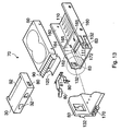
- Figure 13 illustrates one example of how light pipes 172 may be employed to carry indicator signals from the media drive 50 to the front of the drive carrier 70.
- the base portion 110 includes a front portion 111, which extends between the sides 160 and toward the front of the drive carrier 70.
- the front portion 111 has mounted within it three light pipes (shown as the dashed line in Figure 13 ).
- the light pipes 172 terminates at the front of the front portion 111, where appropriate caps 170 may be provided.
- the base portion 110 is provided with a dividing wall 164.
- the EMI finger array 90 and EMI contact plate 120 in this example can be mounted on the dividing wall 164 using attachments 165 such as screw attachments, rivets or spot welds. When mounted, the EMI contact plate 120 can align with and extend through an aperture 162, which is provided in the front portion 111 of the base portion 110.
- ESD fingers may be provided. These ESD fingers may, for example, be mounted on the sides 160 of the drive carrier 70.
- the handle portion 30 can include features 32 for facilitating a user to grip the handle portion 30.
- a curved slot 32 is provided on the handle portion to allow a users fingers to engage with the underside of the handle portion 30.
- two depressions 32 are formed in the handle portion 30 for a user to hold.
- the media drive 50 can be received within a drive carrier such as one of those described above.
- the handle portion 30 of the drive carrier 70 can then be moved to the second position whereby the latch mechanism is in a retracted state. Holding the handle, the user can then, with a single movement, slide the drive carrier holding the media drive 50 into the receiving location 100 of a computer system. As the drive carrier 70 is inserted into the receiving location 100 any connectors on the rear of the media drive 50 will eventually meet and connect with corresponding connectors of the receiving location 100.
- the user can continue to push the handle portion 30 toward the receiving location 100, whereby the handle portion 30 can be actuated from a second position to a first position as described above.
- resilient latch portions such as those described above may deploy through apertures in the handle portion 30 to engage with engaging formations of the receiving location 100 such as apertures which are aligned with the apertures of the handle portion 30.
- a single linear movement when holding the handle portion 30, can be used to both insert the drive carrier 70 into the receiving location 100 and to operate the latch mechanism.
- the movement is a single, linear movement in the direction of insertion of the drive carrier within the receiving location.
- This single movement can also cause the fingers of an EMI finger array to be deployed to urge against, for example, a wall of the receiving location 100 as described above.
- a user can move the handle portion 30 from the first position to the second position which, as described above, operates the latch mechanism to move into a retracted state.
- resilient latch portions of the latching mechanism may be caused to retract through apertures in the handle portion 30.
- the user may continue to pull on the handle portion 30 to disconnect any connectors of the media drive 50 from corresponding connectors within the receiving location 100 and to withdraw the drive carrier from the receiving location 100.
- a single linear movement allows the latch mechanism to be operated to move into a retracted state and also allows the drive carrier 70 to be withdrawn from the receiving location 100.
- the movement is a single, linear movement in the direction of withdrawl of the drive carrier from the receiving location.
- this single linear movement may also cause the retraction of the fingers of an EMI finger array where such an array is provided. Retraction of any EMI fingers is beneficial prior to withdrawal of the drive carrier 70 from the receiving location 100, since this reduces sliding resistance and also prevents damage (scraping) of neighbouring components such as a neighbouring media drive.
Landscapes
- Engineering & Computer Science (AREA)
- Theoretical Computer Science (AREA)
- General Physics & Mathematics (AREA)
- Human Computer Interaction (AREA)
- Physics & Mathematics (AREA)
- General Engineering & Computer Science (AREA)
- Power Engineering (AREA)
- Computer Hardware Design (AREA)
- Casings For Electric Apparatus (AREA)
- Die Bonding (AREA)
- Control Of Motors That Do Not Use Commutators (AREA)
- Input Circuits Of Receivers And Coupling Of Receivers And Audio Equipment (AREA)
- Automatic Analysis And Handling Materials Therefor (AREA)
Claims (26)
- Laufwerkträger (70) welcher so ausgestattet ist, dass er ein Medienlaufwerk (50) aufnimmt und weiterhin so ausgestattet ist, dass er abnehmbar in einer Aufnahmestelle (24) eines Computersystems (10) aufnehmbar ist, wobei der Träger aufweist:einen Basisabschnitt (110),einen Handgriffabschnitt (30), undeinen Verriegelungsmechanismus (80), welcher einen nachgiebigen Verriegelungsabschnitt aufweist, um den Träger in der Aufnahmestelle zu sichern,wobei der Basisabschnitt und der Handgriffabschnitt so ausgestaltet sind, dass sie in der Weise zusammenwirken, dass sie den Verriegelungsmechanismus beim Einsetzen oder beim Herausnehmen des Trägers aus der Aufnahmestelle betätigen, um den Träger in die Aufnahmestelle einzusetzen oder aus dieser zu entnehmen, und wobei sie den Verriegelungsmechanismus mit einer einzigen Bewegung des Handgriffabschnittes betätigen,wobei der Handgriffabschnitt so betätigbar ist, dass er sich von einer ersten Position in eine zweite Position relativ zu dem Basisabschnitt bewegt, um den Verriegelungsmechanismus durch eine lineare Bewegung in Richtung der Entnahme des Laufwerkträgers bezüglich der Aufnahmestelle zu bewegen, wobei der Verriegelungsmechanismus sich in einem eingesetzten bzw. ausgefahrenen Zustand befindet, um den Laufwerkträger an der Aufnahmestelle zu sichern, wenn der Handgriff sich in der ersten Position befindet, und der Verriegelungsmechanismus sich in einem zurückgezogenen Zustand befindet, um ein Einsetzen des Laufwerkträgers in die Aufnahmestelle und/oder eine Entnahme des Laufwerkträgers aus der Aufnahmestelle zu ermöglichen, wenn der Handgriff sich in der zweiten Position befindet.
- Laufwerkträger nach Anspruch 1, wobei der Verriegelungsmechanismus eine Öffnung in dem Handgriffabschnitt aufweist, wobei dann, wenn der Verriegelungsmechanismus sich in dem eingesetzten Zustand befindet, der Verriegelungsabschnitt durch die Öffnung in dem Handgriffabschnitt hervorsteht, um mit einem Gestaltungselement der Aufnahmestelle in Eingriff zu treten und wobei eine Bewegung des Handgriffs aus der ersten Position in die zweite Position bewirkt, dass der Verriegelungsabschnitt durch die Öffnung in dem Handgriffabschnitt zurückgezogen wird.
- Laufwerkträger nach Anspruch 2, wobei der Verriegelungsabschnitt mit dem Basisabschnitt einstückig ausgebildet ist.
- Laufwerkträger nach Anspruch 2 oder 3, wobei der Verriegelungsabschnitt einen gefalteten Abschnitt aus einem federnden Metall aufweist.
- Laufwerkträger nach einem der Ansprüche 2 bis 4, wobei dann, wenn der Verriegelungsmechanismus sich in dem zurückgezogenen Zustand befindet, der Verriegelungsabschnitt gegen eine innere Fläche des Handgriffabschnitts drückt.
- Laufwerkträger nach einem der vorstehenden Ansprüche, welcher weiterhin eine oder mehrere Führungsschienen für eine Führungsbewegung des Handgriffabschnittes zwischen der ersten Position und der zweiten Position aufweist.
- Laufwerkträger nach Anspruch 6, wobei der Handgriffabschnitt ein oder mehrere Schlitten aufweist, die in den Führungsschienen angeordnet sind.
- Laufwerkträger nach Anspruch 6 oder 7, wobei die Führungsschienen einstückig mit dem Basisteil ausgebildet sind.
- Laufwerkträger nach einem der Ansprüche 6 bis 8, wobei die Führungsschienen aus einem Kunststoffmaterial hergestellt sind.
- Laufwerkträger nach einem der vorstehenden Ansprüche, welcher weiterhin eine Mehrzahl elektromagnetischer (EMI) Finger (74) aufweist, die so ausgestaltet sind, dass sie folgendes einnehmen:eine Einsatzposition zum Anliegen an einem benachbarten Laufwerkträger, einem Mediumlaufwerk oder der inneren Wand der Aufnahmestelle, undeine zurückgezogene Position für das Vermindern des Gleitwiderstandes beim Einsetzen und/oder Entfernen des Laufwerkträgers in die bzw. aus der Aufnahmestelle.
- Laufwerkträger nach Anspruch 10, wobei der Handgriffabschnitt so betätigbar ist, dass er sich zwischen einer ersten Position und einer zweiten Position relativ zu dem Basisabschnitt bewegt, um den Verriegelungsmechanismus zu betätigen und um die EMI-Finger zwischen der eingesetzten und der zurückgezogenen Positionen zu bewegen, und wobei die einzige Bewegung des Handgriffabschnittes das Betätigen des Handgriffes zwischen der ersten Position und der zweiten Position umfasst.
- Laufwerkträger nach Anspruch 11, wobei die EMI-Finger relativ zu dem Basisabschnitt fixiert sind und wobei der Handgriffabschnitt eine Rampe aufweist, auf welcher die EMI-Finger auflaufen können, wodurch eine Bewegung des Handgriffabschnittes aus der zweiten Position in die erste Position bewirkt, dass der Rampenabschnitt die EMI-Finger in die eingesetzte Position drückt.
- Laufwerkträger nach einem der Ansprüche 10 bis 12, wobei die EMI-Finger mit dem Basisabschnitt einstückig ausgebildet sind.
- Laufwerkträger nach einem der vorstehenden Ansprüche, wobei der Handgriffabschnitt einen oder mehrere Hohllichtleiter aufweist, um Licht von einem Anzeigelicht eines aufgenommenen Medienlaufwerkes zu leiten.
- Laufwerkträger nach einem der vorstehenden Ansprüche, welcher einen oder mehrere elektrostatische Entladungsfinger (ESD-Finger) aufweist, die so ausgestaltet sind, dass sie gegen eine innere Wand der Aufnahmestelle drücken, wenn der Laufwerkträger in der Aufnahmestelle aufgenommen ist.
- Laufwerkträger nach Anspruch 15, wobei einer oder mehrere der ESD-Finger einstückig mit dem Basisabschnitt ausgebildet sind.
- Laufwerkträger nach einem der vorstehenden Ansprüche, welcher weiterhin eine oder mehrere Ausgestaltungen für eine Führungsbewegung des Trägers innerhalb der Aufnahmestelle aufweist.
- Laufwerkträger nach einem der vorstehenden Ansprüche, wobei der Basisabschnitt ein Metallblech aufweist.
- Laufwerkträger nach einem der vorstehenden Ansprüche, wobei der Basisabschnitt ein Kunststoffmaterial aufweist.
- Laufwerkträger nach einem der vorstehenden Ansprüche, welcher ein darin aufgenommenes Medienlaufwerk hat.
- Computersystem, welches aufweist:eine Aufnahmestelle, undden Laufwerkträger nach einem der vorstehenden Ansprüche, der herausnehmbar in der Aufnahmestelle aufgenommen ist.
- Computersystem nach Anspruch 21, welches weiterhin zumindest einen zusätzlichen Laufwerkträger und ein Medienlaufwerk aufweist, die in der Aufnahmestelle aufgenommen sind.
- Verfahren zum Entnehmen eines Medienlaufwerks (50) aus einem Computersystem (10), wobei das Verfahren aufweist:Bereitstellen eines Laufwerkträgers (70) in welchem das Medienlaufwerk aufgenommen ist, wobei der Laufwerkträger herausnehmbar in einer Aufnahmestelle des Computersystems aufgenommen ist und wobei der Laufwerkträger aufweist:einen Basisabschnitt (110),einen Handgriffabschnitt (30) undeinen Verriegelungsmechanismus, welcher einen nachgiebigen Verriegelungsabschnitt aufweist, um den Träger in der Aufnahmestelle zu sichern,wobei der Basisabschnitt und der Handgriffabschnitt so ausgestaltet sind, dass sie in der Weise zusammenwirken, dass sie den Verriegelungsmechanismus beim Einsetzen und/oder Herausnehmen des Trägers in die bzw. aus der Aufnahmestelle betätigen, um den Träger in die Aufnahmestelle einzusetzen,und/oder aus dieser herauszunehmen, und zum Betätigen des Verriegelungsmechanismus mit einer einzigen Bewegung des Handgriffabschnittes, undBewegen des Handgriffs zum Betätigen des Verriegelungsmechanismus und zum Entnehmen des Trägers aus der Aufnahmestelle, was das Betätigen des Handgriffabschnittes relativ zu dem Basisabschnitt mit einer einzigen linearen Bewegung in Richtung der Entnahme des Laufwerkträgers aus der Aufnahmestelle aus der ersten Position einschließt, in welcher der Verriegelungsmechanismus in einem eingesetzten Zustand ist, um den Laufwerkträger in der Aufnahmestelle zu sichern, hin zu einer zweiten Position, in welcher der Verriegelungsmechanismus sich in einem zurückgezogenen Zustand befindet.
- Verfahren nach Anspruch 23, wobei die einzige Bewegung anschließend das gleitende Bewegen des Laufwerkträgers und des Medienlaufwerks aus der Aufnahmestelle heraus umfasst.
- Verfahren zum Einsetzen eines Medienlaufwerks (50) in ein Computersystem (10), wobei das Verfahren aufweist:Bereitstellen eines Laufwerkträgers (70) in welchem das Medienlaufwerk aufgenommen ist, wobei der Laufwerkträger aufweist:einen Basisabschnitt (110),einen Handgriffabschnitt (30) undeinen Verriegelungsmechanismus (80), welcher einen nachgiebigen Verriegelungsabschnitt aufweist, um den Träger in der Aufnahmestelle zu sichern,wobei der Basisabschnitt und der Handgriffabschnitt so ausgestaltet sind, dass sie in der Weise zusammenwirken, dass sie den Verriegelungsmechanismus beim Einsetzen des Trägers und/oder beim Entnehmen desselben in bzw. aus der Aufnahmestelle betätigen, um den Träger in die Aufnahmestelle einzusetzen und/oder aus dieser herauszunehmen, und Betätigen des Verriegelungsmechanismus mit einer einzigen Bewegung des Handgriffabschnittes, undBewegen des Handgriffabschnittes, um den Träger in die Aufnahmestelle einzusetzen und um den Verriegelungsmechanismus zu betätigen, einschließlich einer Betätigung des Handgriffabschnittes relativ zu dem Basisabschnitt mit einer einzigen, linearen Bewegung in Richtung des Einsetzens des Laufwerkträgers in die Aufnahmestelle aus einer zweiten Position heraus, in welcher der Verriegelungsmechanismus sich in einem zurückgezogenen Zustand befindet, in eine erste Position hinein, in welcher der Verriegelungsmechanismus in einem eingesetzten Zustand ist, um den Laufwerkträger in der Aufnahmestelle zu halten.
- Verfahren nach Anspruch 25, wobei die einzige Bewegung das gleitende Bewegen des Laufwerkträgers und des Medienlaufwerks in die Aufnahmestelle sowie das Betätigen des Handgriffabschnittes relativ zu dem Basisabschnitt umfasst.
Applications Claiming Priority (2)
| Application Number | Priority Date | Filing Date | Title |
|---|---|---|---|
| US10/862,687 US7280352B2 (en) | 2004-06-07 | 2004-06-07 | Drive carrier |
| PCT/US2005/019655 WO2005121931A1 (en) | 2004-06-07 | 2005-06-03 | Drive carrier |
Publications (2)
| Publication Number | Publication Date |
|---|---|
| EP1759263A1 EP1759263A1 (de) | 2007-03-07 |
| EP1759263B1 true EP1759263B1 (de) | 2010-08-04 |
Family
ID=35058989
Family Applications (1)
| Application Number | Title | Priority Date | Filing Date |
|---|---|---|---|
| EP05758789A Expired - Lifetime EP1759263B1 (de) | 2004-06-07 | 2005-06-03 | Laufwerkträger |
Country Status (5)
| Country | Link |
|---|---|
| US (1) | US7280352B2 (de) |
| EP (1) | EP1759263B1 (de) |
| AT (1) | ATE476695T1 (de) |
| DE (1) | DE602005022710D1 (de) |
| WO (1) | WO2005121931A1 (de) |
Families Citing this family (70)
| Publication number | Priority date | Publication date | Assignee | Title |
|---|---|---|---|---|
| US7259966B2 (en) * | 2004-08-31 | 2007-08-21 | International Business Machines Corporation | Apparatus, system, and method for reducing rotational vibration transmission within a data storage system |
| TWI258330B (en) * | 2004-12-10 | 2006-07-11 | Asustek Comp Inc | Shockproof locking assembly device |
| JP2006172675A (ja) * | 2004-12-20 | 2006-06-29 | Hitachi Global Storage Technologies Netherlands Bv | 回転円板形記憶装置の取付構造及び取付方法 |
| TWM275448U (en) * | 2005-03-21 | 2005-09-11 | Compal Electronics Inc | Positioning apparatus for data storage device |
| US7654706B2 (en) * | 2006-01-25 | 2010-02-02 | Cooper Technologies Company | Method and apparatus for securing a door to a lighting device chassis |
| US7499271B2 (en) * | 2006-03-20 | 2009-03-03 | International Business Machines Corporation | Hard disk enclosure blade |
| US8111514B2 (en) * | 2006-04-21 | 2012-02-07 | Maxvision Corporation | Removable hard drive module for a computer with improved thermal performance |
| US7542295B2 (en) * | 2006-04-21 | 2009-06-02 | Maxvision Corporation | Removable hard drive module for a computer |
| US7627221B2 (en) * | 2006-06-23 | 2009-12-01 | Stephen James Morris | Mounting system for telecommunications panels |
| US7996174B2 (en) | 2007-12-18 | 2011-08-09 | Teradyne, Inc. | Disk drive testing |
| US8549912B2 (en) * | 2007-12-18 | 2013-10-08 | Teradyne, Inc. | Disk drive transport, clamping and testing |
| CN101515470B (zh) * | 2008-02-21 | 2011-06-22 | 鸿富锦精密工业(深圳)有限公司 | 硬盘固定装置 |
| US8102173B2 (en) | 2008-04-17 | 2012-01-24 | Teradyne, Inc. | Thermal control system for test slot of test rack for disk drive testing system with thermoelectric device and a cooling conduit |
| US8238099B2 (en) | 2008-04-17 | 2012-08-07 | Teradyne, Inc. | Enclosed operating area for disk drive testing systems |
| US8095234B2 (en) | 2008-04-17 | 2012-01-10 | Teradyne, Inc. | Transferring disk drives within disk drive testing systems |
| US8160739B2 (en) | 2008-04-17 | 2012-04-17 | Teradyne, Inc. | Transferring storage devices within storage device testing systems |
| US8305751B2 (en) | 2008-04-17 | 2012-11-06 | Teradyne, Inc. | Vibration isolation within disk drive testing systems |
| US7848106B2 (en) | 2008-04-17 | 2010-12-07 | Teradyne, Inc. | Temperature control within disk drive testing systems |
| US8117480B2 (en) | 2008-04-17 | 2012-02-14 | Teradyne, Inc. | Dependent temperature control within disk drive testing systems |
| US20090262455A1 (en) | 2008-04-17 | 2009-10-22 | Teradyne, Inc. | Temperature Control Within Disk Drive Testing Systems |
| US7945424B2 (en) | 2008-04-17 | 2011-05-17 | Teradyne, Inc. | Disk drive emulator and method of use thereof |
| US8041449B2 (en) | 2008-04-17 | 2011-10-18 | Teradyne, Inc. | Bulk feeding disk drives to disk drive testing systems |
| US7782606B2 (en) * | 2008-05-12 | 2010-08-24 | International Business Machines Corporation | Hard disk drive carrier latch apparatus |
| US8023263B2 (en) * | 2008-05-12 | 2011-09-20 | International Business Machines Corporation | Latch for securing a hardware component into a component bay |
| CN102112887B (zh) | 2008-06-03 | 2015-06-10 | 泰拉丁公司 | 处理存储设备 |
| KR100960098B1 (ko) * | 2009-02-13 | 2010-05-31 | (주)넷메이커 | 서버 컴퓨터용 하드디스크 드라이브의 핫스왑 랙 및 이를 구비한 서버 컴퓨터 |
| JP2010243719A (ja) * | 2009-04-03 | 2010-10-28 | Victor Co Of Japan Ltd | 筐体組み立て構造及び画像表示装置 |
| US8264822B2 (en) * | 2009-03-30 | 2012-09-11 | JVC Kenwood Corporation | Image display apparatus and housing assembly configuration |
| USD624539S1 (en) * | 2009-06-12 | 2010-09-28 | A-Data Technology (Suzhou) Co., Ltd. | Portable electronic storage device |
| US8628239B2 (en) * | 2009-07-15 | 2014-01-14 | Teradyne, Inc. | Storage device temperature sensing |
| US7920380B2 (en) | 2009-07-15 | 2011-04-05 | Teradyne, Inc. | Test slot cooling system for a storage device testing system |
| US8466699B2 (en) | 2009-07-15 | 2013-06-18 | Teradyne, Inc. | Heating storage devices in a testing system |
| US8687356B2 (en) | 2010-02-02 | 2014-04-01 | Teradyne, Inc. | Storage device testing system cooling |
| US8116079B2 (en) | 2009-07-15 | 2012-02-14 | Teradyne, Inc. | Storage device testing system cooling |
| US8547123B2 (en) | 2009-07-15 | 2013-10-01 | Teradyne, Inc. | Storage device testing system with a conductive heating assembly |
| US7995349B2 (en) * | 2009-07-15 | 2011-08-09 | Teradyne, Inc. | Storage device temperature sensing |
| US8035961B2 (en) * | 2009-10-06 | 2011-10-11 | Dell Products L.P. | Controlled compression of hard drive carrier CAM |
| US8320116B2 (en) * | 2010-04-29 | 2012-11-27 | Sanmina-Sci Corporation | Multi-use removable electronic data storage device carrier module |
| US9779780B2 (en) | 2010-06-17 | 2017-10-03 | Teradyne, Inc. | Damping vibrations within storage device testing systems |
| US8687349B2 (en) | 2010-07-21 | 2014-04-01 | Teradyne, Inc. | Bulk transfer of storage devices using manual loading |
| US9001456B2 (en) | 2010-08-31 | 2015-04-07 | Teradyne, Inc. | Engaging test slots |
| WO2012054061A1 (en) * | 2010-10-22 | 2012-04-26 | Hewlett-Packard Development Company, L.P. | Handle module |
| TWI459383B (zh) | 2010-10-29 | 2014-11-01 | Ibm | 承載裝置、主機與組裝主機的方法 |
| DE112011105760T5 (de) | 2011-10-25 | 2014-11-13 | Hewlett-Packard Development Company, L.P. | Lichtquellensteuerung für Laufwerksträger |
| US8611093B2 (en) | 2011-10-25 | 2013-12-17 | Dell Products, Lp | Top accessible disk drive carrier for horizontally mounted hard drive |
| US9459312B2 (en) | 2013-04-10 | 2016-10-04 | Teradyne, Inc. | Electronic assembly test system |
| TWI584276B (zh) * | 2013-09-18 | 2017-05-21 | 樺漢科技股份有限公司 | 接地件及設有該接地件的硬碟機固定裝置 |
| US9437250B2 (en) | 2014-01-31 | 2016-09-06 | Dell Products, Lp | Hard drive carrier that locks in a shipping position |
| US9886069B2 (en) | 2014-02-06 | 2018-02-06 | Hewlett Packard Enterprise Development Lp | Disk drive module |
| CN105578833B (zh) * | 2014-10-14 | 2019-06-28 | 鸿富锦精密电子(天津)有限公司 | 滑轨连锁装置及设有该滑轨连锁装置的电子装置 |
| US9420718B2 (en) * | 2014-11-19 | 2016-08-16 | Dell Products, L.P. | Adjustable device carrier for modular chassis |
| US9538682B1 (en) * | 2015-09-25 | 2017-01-03 | International Business Machines Corporation | Strengthening electronic equipment |
| WO2017127048A1 (en) * | 2016-01-19 | 2017-07-27 | Hewlett Packard Enterprise Development Lp | Support devices for drive carrier electromagnetic interference shields |
| US10845410B2 (en) | 2017-08-28 | 2020-11-24 | Teradyne, Inc. | Automated test system having orthogonal robots |
| US10725091B2 (en) | 2017-08-28 | 2020-07-28 | Teradyne, Inc. | Automated test system having multiple stages |
| US11226390B2 (en) | 2017-08-28 | 2022-01-18 | Teradyne, Inc. | Calibration process for an automated test system |
| US10948534B2 (en) | 2017-08-28 | 2021-03-16 | Teradyne, Inc. | Automated test system employing robotics |
| US10983145B2 (en) | 2018-04-24 | 2021-04-20 | Teradyne, Inc. | System for testing devices inside of carriers |
| US10775408B2 (en) | 2018-08-20 | 2020-09-15 | Teradyne, Inc. | System for testing devices inside of carriers |
| CN112083765B (zh) * | 2019-06-14 | 2023-01-06 | 纬联电子科技(中山)有限公司 | 服务器设备及其托盘机构 |
| CN114333922B (zh) * | 2020-09-27 | 2023-09-08 | 华为技术有限公司 | 一种硬盘托架、硬盘及电子设备 |
| US11953519B2 (en) | 2020-10-22 | 2024-04-09 | Teradyne, Inc. | Modular automated test system |
| US11754622B2 (en) | 2020-10-22 | 2023-09-12 | Teradyne, Inc. | Thermal control system for an automated test system |
| US11754596B2 (en) | 2020-10-22 | 2023-09-12 | Teradyne, Inc. | Test site configuration in an automated test system |
| US11899042B2 (en) | 2020-10-22 | 2024-02-13 | Teradyne, Inc. | Automated test system |
| US11867749B2 (en) | 2020-10-22 | 2024-01-09 | Teradyne, Inc. | Vision system for an automated test system |
| US12007411B2 (en) | 2021-06-22 | 2024-06-11 | Teradyne, Inc. | Test socket having an automated lid |
| US12016167B2 (en) | 2022-04-11 | 2024-06-18 | Dell Products L.P. | Tear-drop shaped HDD carrier EMI finger |
| US20250324530A1 (en) * | 2024-04-12 | 2025-10-16 | Sanmina Corporation | Drive carrier for data storage systems |
| EP4650911A1 (de) * | 2024-05-13 | 2025-11-19 | Samsung Electronics Co., Ltd. | Speichervorrichtung, elektronische vorrichtung damit und betriebsverfahren der elektronischen vorrichtung |
Family Cites Families (56)
| Publication number | Priority date | Publication date | Assignee | Title |
|---|---|---|---|---|
| US3193342A (en) | 1963-05-27 | 1965-07-06 | Deutsch Fastener Corp | Latch handle |
| US3899794A (en) | 1973-11-30 | 1975-08-12 | Wangco Inc | Front loading disc drive apparatus |
| US4421372A (en) | 1979-06-13 | 1983-12-20 | The Babcock & Wilcox Company | Insertion-withdrawal mechanism for rack mounted circuit boards |
| US4365831A (en) | 1980-04-04 | 1982-12-28 | Hartwell Corporation | Channel latch |
| US4597173A (en) | 1984-06-20 | 1986-07-01 | The United States Of America As Represented By The Secretary Of The Navy | Electronic module insertion and retraction mechanism |
| US4778401A (en) | 1987-05-28 | 1988-10-18 | Digital Equipment Corporation | Extraction-insertion card guide mechanism |
| US4941841A (en) | 1988-06-09 | 1990-07-17 | Darden Julius C | Adapter and a removable slide-in cartridge for an information storage system |
| US4872853A (en) | 1988-12-08 | 1989-10-10 | Amp Incorporated | Circuit card retaining device |
| US5003431A (en) | 1989-12-18 | 1991-03-26 | Unisys Corporation | Insertion, extraction, and clamping apparatus for electrical modules |
| JPH04169917A (ja) | 1990-05-07 | 1992-06-17 | Toshiba Corp | 携帯型電子機器 |
| US5504648A (en) | 1991-09-06 | 1996-04-02 | Kabushiki Kaisha Toshiba | Electronic apparatus and electronic system with expanding apparatus having interlock, ejector, grounding, and lock mechanisms, for expanding function of electronic apparatus |
| US5172520A (en) | 1991-09-16 | 1992-12-22 | Vinyl Tech | Window assembly having a horizontally slidable window unit latchable in a closed position |
| US5483419A (en) | 1991-09-24 | 1996-01-09 | Teac Corporation | Hot-swappable multi-cartridge docking module |
| US5222897A (en) | 1992-04-01 | 1993-06-29 | Emc Corporation | Circuit board inserter/ejector system |
| US5332306A (en) | 1992-06-05 | 1994-07-26 | Compaq Computer Corporation | Computer disk drive mounting apparatus |
| US5229919A (en) | 1992-08-20 | 1993-07-20 | Chen Pao Chin | Hard disk drive case with electrical switch and dust guard for receiving a hard disk drive |
| US5277615A (en) * | 1992-09-24 | 1994-01-11 | Compaq Computer Corporation | Apparatus for removably supporting a plurality of hot plug-connected hard disk drives |
| US5653518A (en) | 1993-09-10 | 1997-08-05 | Compaq Computer Corporation | Quick release drive unit rail members |
| US5442513A (en) | 1994-02-18 | 1995-08-15 | Lo; Hsin Y. | Hard disk drive and casing slidably received within frame having double-swinging door and lock |
| US5557499A (en) | 1994-06-28 | 1996-09-17 | Ast Research, Inc. | Hard-disk drive tray assembly with pivotally rotatable front bezel |
| US5506758A (en) | 1994-09-30 | 1996-04-09 | Hewlett-Packard Company | Circuit board inserter and extractor |
| US5563767A (en) | 1995-05-04 | 1996-10-08 | Chen; Teng-Chun | Drawer type hard diskdrive adapter |
| US5673171A (en) * | 1995-12-05 | 1997-09-30 | Compaq Computer Corporation | Hard disc drive support tray apparatus with built-in handling shock reduction, EMI shielding and mounting alignment structures |
| US5691859A (en) | 1995-12-19 | 1997-11-25 | Exabyte Corporation | Drive with features which adjust and actuate cartridge transport and library with such drive |
| US5673172A (en) | 1996-01-05 | 1997-09-30 | Compaq Computer Corporation | Apparatus for electromagnetic interference and electrostatic discharge shielding of hot plug-connected hard disk drives |
| US5654873A (en) * | 1996-01-29 | 1997-08-05 | Silicon Graphics, Inc. | Single connector attachment drive sled assembly having light pipe coupled to a rail |
| US5734557A (en) | 1996-09-13 | 1998-03-31 | Deli U.S.A., L.P. | Mounting assembly for electronic equipment |
| US5765933A (en) * | 1997-02-13 | 1998-06-16 | Kingston Technology Company | Cam assisted ejection handle for a removable drive carrier |
| US6067225A (en) * | 1997-08-04 | 2000-05-23 | Sun Microsystems, Inc. | Disk drive bracket |
| US6433825B1 (en) | 1997-12-18 | 2002-08-13 | Eastman Kodak Company | EMI-protected eject interface for an electronic device |
| US5980281A (en) | 1998-02-11 | 1999-11-09 | International Business Machines Corporation | Mechanism to assist in insertion or removal of PCI cards |
| US6050658A (en) * | 1998-02-23 | 2000-04-18 | Richmount Computer Limited | Carrier for an electronic device |
| GB2335799B (en) * | 1998-03-27 | 2002-04-03 | Ibm | Electro-magnetic compatibility (EMC) shield |
| GB2336248A (en) * | 1998-04-08 | 1999-10-13 | Ibm | Accessory mounting for digital computer |
| US6277630B1 (en) * | 1998-05-29 | 2001-08-21 | Sorenson Bioscience, Inc. | Expandable sequencing tray |
| US6056567A (en) | 1998-09-22 | 2000-05-02 | Berg Technology, Inc. | Insertion and/or extraction device for electronic component |
| US6193339B1 (en) | 1999-04-12 | 2001-02-27 | Inclose Design, Inc. | Docking adapter for memory storage devices |
| US6473297B1 (en) * | 1999-04-23 | 2002-10-29 | Inclose Design, Inc. | Memory storage device docking adapted having a laterally mounted fan |
| US6288902B1 (en) | 1999-05-25 | 2001-09-11 | Hewlett-Packard Company | Modular data storage system for reducing mechanical shock and vibrations |
| US6252514B1 (en) | 1999-06-07 | 2001-06-26 | Convergent Technologies, Inc. | Hot-swap assembly for computers |
| US6460948B2 (en) * | 1999-10-29 | 2002-10-08 | Hewlett-Packard Company | Drive bracket |
| JP2001185880A (ja) | 1999-12-22 | 2001-07-06 | Nec Corp | 誤挿入防止機構及び誤挿入防止システム |
| US6480391B1 (en) * | 2000-01-12 | 2002-11-12 | International Business Machines Corporation | Modular cage for an electronic component |
| US6421236B1 (en) * | 2000-08-07 | 2002-07-16 | Intel Corporation | Hot swap disk drive carrier and disk drive bay |
| US6373713B1 (en) | 2000-09-28 | 2002-04-16 | Oresis Communications | Single handle printed circuit board assembly insertion, extraction, sensing and locking mechanism |
| GB2371413A (en) * | 2001-01-17 | 2002-07-24 | Sun Microsystems Inc | Removable media drives |
| US6802117B2 (en) | 2001-02-05 | 2004-10-12 | George Dalisay | Device for circuit board insertion and extraction |
| US20030033463A1 (en) * | 2001-08-10 | 2003-02-13 | Garnett Paul J. | Computer system storage |
| US6665908B1 (en) * | 2001-10-31 | 2003-12-23 | Unisys Corporation | Modular computer system and latching handle for same |
| US6618264B2 (en) | 2001-11-28 | 2003-09-09 | Hewlett-Packard-Company, L.P. | Tool-less coupling system for electronic modules |
| US6826056B2 (en) * | 2001-12-11 | 2004-11-30 | Hewlett-Packard Development Company, L.P. | Systems for use with data storage devices |
| WO2003073246A1 (en) * | 2002-02-26 | 2003-09-04 | Fujitsu Limited | Electronic apparatus and function extension device for extending function of electronic apparatus |
| US6820953B2 (en) * | 2002-03-22 | 2004-11-23 | Frank Wojcik | Memory storage device carrier having a locking handle |
| US6795307B2 (en) | 2002-10-31 | 2004-09-21 | Hewlett-Packard Development Company, L.P. | Tool-less latch mechanism for an enclosure panel |
| US7054965B2 (en) * | 2003-03-18 | 2006-05-30 | Oqo Incorporated | Component for use as a portable computing device and pointing device |
| US7139166B2 (en) * | 2004-09-14 | 2006-11-21 | Dell Products L.P. | Hard drive carrier |
-
2004
- 2004-06-07 US US10/862,687 patent/US7280352B2/en not_active Expired - Lifetime
-
2005
- 2005-06-03 WO PCT/US2005/019655 patent/WO2005121931A1/en not_active Ceased
- 2005-06-03 AT AT05758789T patent/ATE476695T1/de not_active IP Right Cessation
- 2005-06-03 EP EP05758789A patent/EP1759263B1/de not_active Expired - Lifetime
- 2005-06-03 DE DE602005022710T patent/DE602005022710D1/de not_active Expired - Lifetime
Also Published As
| Publication number | Publication date |
|---|---|
| WO2005121931A1 (en) | 2005-12-22 |
| US20050270737A1 (en) | 2005-12-08 |
| DE602005022710D1 (de) | 2010-09-16 |
| ATE476695T1 (de) | 2010-08-15 |
| US7280352B2 (en) | 2007-10-09 |
| EP1759263A1 (de) | 2007-03-07 |
Similar Documents
| Publication | Publication Date | Title |
|---|---|---|
| EP1759263B1 (de) | Laufwerkträger | |
| US7272012B2 (en) | Removable storage modules | |
| EP0834880B1 (de) | Montageanordnung für die Befestigung einer Systemeinheit | |
| US7369403B2 (en) | Mounting apparatus for securing storage device | |
| US6373690B1 (en) | Apparatus for mounting a panel to a chassis of a computer | |
| US7254017B2 (en) | Storage device assembly | |
| US6421236B1 (en) | Hot swap disk drive carrier and disk drive bay | |
| US5673172A (en) | Apparatus for electromagnetic interference and electrostatic discharge shielding of hot plug-connected hard disk drives | |
| US7466544B2 (en) | Latching mechanism | |
| US8083197B2 (en) | Mounting apparatus for data storage device | |
| EP3772244B1 (de) | Gehäusemodul zur installation verschiedener module und elektronische vorrichtung damit | |
| US20060146490A1 (en) | Mounting assembly of computer enclosure | |
| US20130176676A1 (en) | Self-latching storage device module | |
| US20070205010A1 (en) | Mounting apparatus for data storage device | |
| US20110173805A1 (en) | Hard-disk Drive Insertion | |
| WO2013039644A1 (en) | Push-push eject disk drive chassis | |
| US6634898B2 (en) | Switch mechanism for online replacement of PCI cards | |
| CN101907907A (zh) | 电子装置 | |
| US8474769B2 (en) | Mounting apparatus for back panel | |
| US7841565B2 (en) | Mounting apparatus for data storage devices | |
| US12443250B2 (en) | Electronic device having keying mechanisms for a drive carrier and a drive cage | |
| US8363395B2 (en) | Release mechanism for electronic device unit and disk array device | |
| US20070246948A1 (en) | Mounting apparatus for data storage device | |
| US8305749B2 (en) | Detachable clip mechanism and related computer system | |
| US20060056103A1 (en) | Cartridge carrier |
Legal Events
| Date | Code | Title | Description |
|---|---|---|---|
| PUAI | Public reference made under article 153(3) epc to a published international application that has entered the european phase |
Free format text: ORIGINAL CODE: 0009012 |
|
| 17P | Request for examination filed |
Effective date: 20061222 |
|
| AK | Designated contracting states |
Kind code of ref document: A1 Designated state(s): AT BE BG CH CY CZ DE DK EE ES FI FR GB GR HU IE IS IT LI LT LU MC NL PL PT RO SE SI SK TR |
|
| DAX | Request for extension of the european patent (deleted) | ||
| 17Q | First examination report despatched |
Effective date: 20080328 |
|
| GRAP | Despatch of communication of intention to grant a patent |
Free format text: ORIGINAL CODE: EPIDOSNIGR1 |
|
| GRAS | Grant fee paid |
Free format text: ORIGINAL CODE: EPIDOSNIGR3 |
|
| GRAA | (expected) grant |
Free format text: ORIGINAL CODE: 0009210 |
|
| AK | Designated contracting states |
Kind code of ref document: B1 Designated state(s): AT BE BG CH CY CZ DE DK EE ES FI FR GB GR HU IE IS IT LI LT LU MC NL PL PT RO SE SI SK TR |
|
| REG | Reference to a national code |
Ref country code: GB Ref legal event code: FG4D |
|
| REG | Reference to a national code |
Ref country code: CH Ref legal event code: EP |
|
| REG | Reference to a national code |
Ref country code: IE Ref legal event code: FG4D |
|
| REF | Corresponds to: |
Ref document number: 602005022710 Country of ref document: DE Date of ref document: 20100916 Kind code of ref document: P |
|
| RAP2 | Party data changed (patent owner data changed or rights of a patent transferred) |
Owner name: ORACLE AMERICA, INC. |
|
| REG | Reference to a national code |
Ref country code: NL Ref legal event code: VDEP Effective date: 20100804 |
|
| LTIE | Lt: invalidation of european patent or patent extension |
Effective date: 20100804 |
|
| PG25 | Lapsed in a contracting state [announced via postgrant information from national office to epo] |
Ref country code: AT Free format text: LAPSE BECAUSE OF FAILURE TO SUBMIT A TRANSLATION OF THE DESCRIPTION OR TO PAY THE FEE WITHIN THE PRESCRIBED TIME-LIMIT Effective date: 20100804 Ref country code: NL Free format text: LAPSE BECAUSE OF FAILURE TO SUBMIT A TRANSLATION OF THE DESCRIPTION OR TO PAY THE FEE WITHIN THE PRESCRIBED TIME-LIMIT Effective date: 20100804 Ref country code: LT Free format text: LAPSE BECAUSE OF FAILURE TO SUBMIT A TRANSLATION OF THE DESCRIPTION OR TO PAY THE FEE WITHIN THE PRESCRIBED TIME-LIMIT Effective date: 20100804 Ref country code: FI Free format text: LAPSE BECAUSE OF FAILURE TO SUBMIT A TRANSLATION OF THE DESCRIPTION OR TO PAY THE FEE WITHIN THE PRESCRIBED TIME-LIMIT Effective date: 20100804 |
|
| PG25 | Lapsed in a contracting state [announced via postgrant information from national office to epo] |
Ref country code: SI Free format text: LAPSE BECAUSE OF FAILURE TO SUBMIT A TRANSLATION OF THE DESCRIPTION OR TO PAY THE FEE WITHIN THE PRESCRIBED TIME-LIMIT Effective date: 20100804 Ref country code: PT Free format text: LAPSE BECAUSE OF FAILURE TO SUBMIT A TRANSLATION OF THE DESCRIPTION OR TO PAY THE FEE WITHIN THE PRESCRIBED TIME-LIMIT Effective date: 20101206 Ref country code: PL Free format text: LAPSE BECAUSE OF FAILURE TO SUBMIT A TRANSLATION OF THE DESCRIPTION OR TO PAY THE FEE WITHIN THE PRESCRIBED TIME-LIMIT Effective date: 20100804 Ref country code: CY Free format text: LAPSE BECAUSE OF FAILURE TO SUBMIT A TRANSLATION OF THE DESCRIPTION OR TO PAY THE FEE WITHIN THE PRESCRIBED TIME-LIMIT Effective date: 20100804 Ref country code: BG Free format text: LAPSE BECAUSE OF FAILURE TO SUBMIT A TRANSLATION OF THE DESCRIPTION OR TO PAY THE FEE WITHIN THE PRESCRIBED TIME-LIMIT Effective date: 20101104 Ref country code: IS Free format text: LAPSE BECAUSE OF FAILURE TO SUBMIT A TRANSLATION OF THE DESCRIPTION OR TO PAY THE FEE WITHIN THE PRESCRIBED TIME-LIMIT Effective date: 20101204 |
|
| PG25 | Lapsed in a contracting state [announced via postgrant information from national office to epo] |
Ref country code: BE Free format text: LAPSE BECAUSE OF FAILURE TO SUBMIT A TRANSLATION OF THE DESCRIPTION OR TO PAY THE FEE WITHIN THE PRESCRIBED TIME-LIMIT Effective date: 20100804 Ref country code: SE Free format text: LAPSE BECAUSE OF FAILURE TO SUBMIT A TRANSLATION OF THE DESCRIPTION OR TO PAY THE FEE WITHIN THE PRESCRIBED TIME-LIMIT Effective date: 20100804 Ref country code: GR Free format text: LAPSE BECAUSE OF FAILURE TO SUBMIT A TRANSLATION OF THE DESCRIPTION OR TO PAY THE FEE WITHIN THE PRESCRIBED TIME-LIMIT Effective date: 20101105 |
|
| PG25 | Lapsed in a contracting state [announced via postgrant information from national office to epo] |
Ref country code: DK Free format text: LAPSE BECAUSE OF FAILURE TO SUBMIT A TRANSLATION OF THE DESCRIPTION OR TO PAY THE FEE WITHIN THE PRESCRIBED TIME-LIMIT Effective date: 20100804 |
|
| PG25 | Lapsed in a contracting state [announced via postgrant information from national office to epo] |
Ref country code: CZ Free format text: LAPSE BECAUSE OF FAILURE TO SUBMIT A TRANSLATION OF THE DESCRIPTION OR TO PAY THE FEE WITHIN THE PRESCRIBED TIME-LIMIT Effective date: 20100804 Ref country code: EE Free format text: LAPSE BECAUSE OF FAILURE TO SUBMIT A TRANSLATION OF THE DESCRIPTION OR TO PAY THE FEE WITHIN THE PRESCRIBED TIME-LIMIT Effective date: 20100804 Ref country code: SK Free format text: LAPSE BECAUSE OF FAILURE TO SUBMIT A TRANSLATION OF THE DESCRIPTION OR TO PAY THE FEE WITHIN THE PRESCRIBED TIME-LIMIT Effective date: 20100804 Ref country code: RO Free format text: LAPSE BECAUSE OF FAILURE TO SUBMIT A TRANSLATION OF THE DESCRIPTION OR TO PAY THE FEE WITHIN THE PRESCRIBED TIME-LIMIT Effective date: 20100804 Ref country code: IT Free format text: LAPSE BECAUSE OF FAILURE TO SUBMIT A TRANSLATION OF THE DESCRIPTION OR TO PAY THE FEE WITHIN THE PRESCRIBED TIME-LIMIT Effective date: 20100804 |
|
| PLBE | No opposition filed within time limit |
Free format text: ORIGINAL CODE: 0009261 |
|
| STAA | Information on the status of an ep patent application or granted ep patent |
Free format text: STATUS: NO OPPOSITION FILED WITHIN TIME LIMIT |
|
| PG25 | Lapsed in a contracting state [announced via postgrant information from national office to epo] |
Ref country code: ES Free format text: LAPSE BECAUSE OF FAILURE TO SUBMIT A TRANSLATION OF THE DESCRIPTION OR TO PAY THE FEE WITHIN THE PRESCRIBED TIME-LIMIT Effective date: 20101115 |
|
| 26N | No opposition filed |
Effective date: 20110506 |
|
| REG | Reference to a national code |
Ref country code: DE Ref legal event code: R097 Ref document number: 602005022710 Country of ref document: DE Effective date: 20110506 |
|
| REG | Reference to a national code |
Ref country code: CH Ref legal event code: PL |
|
| REG | Reference to a national code |
Ref country code: FR Ref legal event code: ST Effective date: 20120229 |
|
| REG | Reference to a national code |
Ref country code: IE Ref legal event code: MM4A |
|
| PG25 | Lapsed in a contracting state [announced via postgrant information from national office to epo] |
Ref country code: LI Free format text: LAPSE BECAUSE OF NON-PAYMENT OF DUE FEES Effective date: 20110630 Ref country code: IE Free format text: LAPSE BECAUSE OF NON-PAYMENT OF DUE FEES Effective date: 20110603 Ref country code: CH Free format text: LAPSE BECAUSE OF NON-PAYMENT OF DUE FEES Effective date: 20110630 Ref country code: FR Free format text: LAPSE BECAUSE OF NON-PAYMENT OF DUE FEES Effective date: 20110630 |
|
| PG25 | Lapsed in a contracting state [announced via postgrant information from national office to epo] |
Ref country code: MC Free format text: LAPSE BECAUSE OF NON-PAYMENT OF DUE FEES Effective date: 20110630 |
|
| PG25 | Lapsed in a contracting state [announced via postgrant information from national office to epo] |
Ref country code: LU Free format text: LAPSE BECAUSE OF NON-PAYMENT OF DUE FEES Effective date: 20110603 |
|
| PG25 | Lapsed in a contracting state [announced via postgrant information from national office to epo] |
Ref country code: TR Free format text: LAPSE BECAUSE OF FAILURE TO SUBMIT A TRANSLATION OF THE DESCRIPTION OR TO PAY THE FEE WITHIN THE PRESCRIBED TIME-LIMIT Effective date: 20100804 |
|
| PG25 | Lapsed in a contracting state [announced via postgrant information from national office to epo] |
Ref country code: HU Free format text: LAPSE BECAUSE OF FAILURE TO SUBMIT A TRANSLATION OF THE DESCRIPTION OR TO PAY THE FEE WITHIN THE PRESCRIBED TIME-LIMIT Effective date: 20100804 |
|
| REG | Reference to a national code |
Ref country code: DE Ref legal event code: R082 Ref document number: 602005022710 Country of ref document: DE Representative=s name: DENDORFER & HERRMANN PATENTANWAELTE PARTNERSCH, DE |
|
| P01 | Opt-out of the competence of the unified patent court (upc) registered |
Effective date: 20230522 |
|
| PGFP | Annual fee paid to national office [announced via postgrant information from national office to epo] |
Ref country code: GB Payment date: 20240502 Year of fee payment: 20 |
|
| PGFP | Annual fee paid to national office [announced via postgrant information from national office to epo] |
Ref country code: DE Payment date: 20240502 Year of fee payment: 20 |
|
| REG | Reference to a national code |
Ref country code: DE Ref legal event code: R071 Ref document number: 602005022710 Country of ref document: DE |
|
| REG | Reference to a national code |
Ref country code: GB Ref legal event code: PE20 Expiry date: 20250602 |
|
| PG25 | Lapsed in a contracting state [announced via postgrant information from national office to epo] |
Ref country code: GB Free format text: LAPSE BECAUSE OF EXPIRATION OF PROTECTION Effective date: 20250602 |