EP1757811B1 - Attachment plate for a hydrostatic piston machine and method of fabrication of said plate - Google Patents
Attachment plate for a hydrostatic piston machine and method of fabrication of said plate Download PDFInfo
- Publication number
- EP1757811B1 EP1757811B1 EP06023672A EP06023672A EP1757811B1 EP 1757811 B1 EP1757811 B1 EP 1757811B1 EP 06023672 A EP06023672 A EP 06023672A EP 06023672 A EP06023672 A EP 06023672A EP 1757811 B1 EP1757811 B1 EP 1757811B1
- Authority
- EP
- European Patent Office
- Prior art keywords
- connecting plate
- extruded profile
- plate
- connection plate
- produced
- Prior art date
- Legal status (The legal status is an assumption and is not a legal conclusion. Google has not performed a legal analysis and makes no representation as to the accuracy of the status listed.)
- Expired - Fee Related
Links
Images

Classifications
-
- B—PERFORMING OPERATIONS; TRANSPORTING
- B23—MACHINE TOOLS; METAL-WORKING NOT OTHERWISE PROVIDED FOR
- B23P—METAL-WORKING NOT OTHERWISE PROVIDED FOR; COMBINED OPERATIONS; UNIVERSAL MACHINE TOOLS
- B23P13/00—Making metal objects by operations essentially involving machining but not covered by a single other subclass
- B23P13/04—Making metal objects by operations essentially involving machining but not covered by a single other subclass involving slicing of profiled material
-
- B—PERFORMING OPERATIONS; TRANSPORTING
- B22—CASTING; POWDER METALLURGY
- B22D—CASTING OF METALS; CASTING OF OTHER SUBSTANCES BY THE SAME PROCESSES OR DEVICES
- B22D11/00—Continuous casting of metals, i.e. casting in indefinite lengths
- B22D11/009—Continuous casting of metals, i.e. casting in indefinite lengths of work of special cross-section, e.g. I-beams, U-profiles
-
- F—MECHANICAL ENGINEERING; LIGHTING; HEATING; WEAPONS; BLASTING
- F04—POSITIVE - DISPLACEMENT MACHINES FOR LIQUIDS; PUMPS FOR LIQUIDS OR ELASTIC FLUIDS
- F04B—POSITIVE-DISPLACEMENT MACHINES FOR LIQUIDS; PUMPS
- F04B1/00—Multi-cylinder machines or pumps characterised by number or arrangement of cylinders
- F04B1/12—Multi-cylinder machines or pumps characterised by number or arrangement of cylinders having cylinder axes coaxial with, or parallel or inclined to, main shaft axis
- F04B1/14—Multi-cylinder machines or pumps characterised by number or arrangement of cylinders having cylinder axes coaxial with, or parallel or inclined to, main shaft axis having stationary cylinders
- F04B1/141—Details or component parts
- F04B1/145—Housings
-
- F—MECHANICAL ENGINEERING; LIGHTING; HEATING; WEAPONS; BLASTING
- F04—POSITIVE - DISPLACEMENT MACHINES FOR LIQUIDS; PUMPS FOR LIQUIDS OR ELASTIC FLUIDS
- F04B—POSITIVE-DISPLACEMENT MACHINES FOR LIQUIDS; PUMPS
- F04B1/00—Multi-cylinder machines or pumps characterised by number or arrangement of cylinders
- F04B1/12—Multi-cylinder machines or pumps characterised by number or arrangement of cylinders having cylinder axes coaxial with, or parallel or inclined to, main shaft axis
- F04B1/20—Multi-cylinder machines or pumps characterised by number or arrangement of cylinders having cylinder axes coaxial with, or parallel or inclined to, main shaft axis having rotary cylinder block
- F04B1/2014—Details or component parts
- F04B1/2064—Housings
-
- F—MECHANICAL ENGINEERING; LIGHTING; HEATING; WEAPONS; BLASTING
- F04—POSITIVE - DISPLACEMENT MACHINES FOR LIQUIDS; PUMPS FOR LIQUIDS OR ELASTIC FLUIDS
- F04B—POSITIVE-DISPLACEMENT MACHINES FOR LIQUIDS; PUMPS
- F04B53/00—Component parts, details or accessories not provided for in, or of interest apart from, groups F04B1/00 - F04B23/00 or F04B39/00 - F04B47/00
- F04B53/007—Cylinder heads
-
- F—MECHANICAL ENGINEERING; LIGHTING; HEATING; WEAPONS; BLASTING
- F04—POSITIVE - DISPLACEMENT MACHINES FOR LIQUIDS; PUMPS FOR LIQUIDS OR ELASTIC FLUIDS
- F04B—POSITIVE-DISPLACEMENT MACHINES FOR LIQUIDS; PUMPS
- F04B53/00—Component parts, details or accessories not provided for in, or of interest apart from, groups F04B1/00 - F04B23/00 or F04B39/00 - F04B47/00
- F04B53/16—Casings; Cylinders; Cylinder liners or heads; Fluid connections
-
- Y—GENERAL TAGGING OF NEW TECHNOLOGICAL DEVELOPMENTS; GENERAL TAGGING OF CROSS-SECTIONAL TECHNOLOGIES SPANNING OVER SEVERAL SECTIONS OF THE IPC; TECHNICAL SUBJECTS COVERED BY FORMER USPC CROSS-REFERENCE ART COLLECTIONS [XRACs] AND DIGESTS
- Y10—TECHNICAL SUBJECTS COVERED BY FORMER USPC
- Y10T—TECHNICAL SUBJECTS COVERED BY FORMER US CLASSIFICATION
- Y10T29/00—Metal working
- Y10T29/49—Method of mechanical manufacture
- Y10T29/49229—Prime mover or fluid pump making
- Y10T29/49236—Fluid pump or compressor making
Definitions
- the invention relates to the connection plate of a hydrostatic machine, in particular an axial piston machine.
- connection plate in an axial piston machine in bent axis design.
- the connection plate closes an elliptical housing section.
- a formed as a biconvex control lens molded control body is slidably disposed in a circular path-shaped support and pivot bearing in the connection plate.
- the control body has openings for the passage of hydraulic medium.
- connection plates are made of individual slab-cast or forged blanks.
- connection plate can only be changed by high costs in the manufacturing process, for example by a new mold or a new die.
- connection plate which can be manufactured inexpensively and with little effort.
- the terminal plate blank formed as an intermediate step for manufacturing the terminal plate is cut from an extruded profile and not individually cast or forged as in conventional manufacturing processes.
- the extruded profile can be made particularly simple and inexpensive.
- the extruded profile consists at least partially of aluminum, copper or iron or of an alloy with at least one of these metals.
- the connection plate can thereby be easily manufactured with the desired material properties.
- the extruded profile covers in cross-section with the contour of the finished connection plate.
- the cut from the extruded connection plate blank must then not be reworked in its contour.
- the extruded profile is cut to at least two terminal board blanks.
- the manufacturing process is much easier, since a plurality of terminal plate blanks can be produced in a simple manner from an extruded profile.
- connection plate according to the invention and the inventive method for producing the connection plate on the basis of FIGS. 2 and 3 will be described using the Fig. 1 a hydrostatic machine with a connection plate according to the prior art for a better understanding of the invention explained.
- the in the Fig. 1 shown axial piston machine is designed in swash plate design with adjustable displacement volume and a current direction and includes in a known manner as essential components a hollow cylindrical housing 1 with a frontally open end (upper end in FIG. 1 ), a housing 1 attached to the open end closing terminal plate 2, a lifting or swash plate 3, a control body 4, a drive shaft 5, a cylinder drum 6 and in the illustrated embodiment, an optional cooling circuit 7.1.
- the swash plate 3 is formed as a so-called pivoting cradle with a semi-cylindrical cross-section and is supported by two spaced parallel to the pivot direction bearing surfaces under hydrostatic discharge to two correspondingly shaped bearing shells 8, attached to the inner surface of the terminal plate 2 opposite housing end wall 9 are.
- the hydrostatic discharge takes place in a known manner via pressure pockets 10 which are formed in the bearing shells 8 and are supplied via connections 11 with pressure medium.
- Actuator 13 engages over an extending in the direction of the terminal plate 2 arm 14 on the swash plate 3 and serves to pivot the same about a pivot axis perpendicular to the pivot axis.
- the control body 4 is fixed to the housing interior facing the inner surface of the connection plate 2 and provided with two through openings 15 in the form of kidney-shaped control slots, which via a pressure channel 16D and suction channel 16S in the connection plate 2 to a pressure and suction line, not shown are connected.
- the pressure channel 16D has a smaller flow area than the suction channel 16S.
- the housing interior facing and spherically formed control surface of the control body 4 serves as a bearing surface for the cylinder drum. 6
- the drive shaft 5 protrudes through a through hole in the housing end wall 9 in the housing 1 and is by means of a bearing 17 in this through hole and by means of another bearing 18 in a narrower bore portion of an end extended blind bore 19 in the terminal plate 2 and one of these narrower bore portion adjacent region of a central through hole 20 in the control body 4 rotatably mounted.
- the drive shaft 5 passes through in the interior of the housing 1 further has a central through hole 21 in the swash plate 3, whose diameter is dimensioned according to the largest swing deflection of the swash plate 3, and a central through hole in the cylinder drum 6 with two bore sections.
- One of these bore sections is integrally formed on the cylinder drum 6, via the Swash plate 3 facing end face 22 protruding sleeve-shaped extension 23 is formed, via which the cylinder drum 6 by means of a splined connection 24 rotatably connected to the drive shaft 5 is connected.
- the remaining bore portion is formed with a conical shape. It tapers from its cross section of largest diameter near the first bore section to its cross section of smallest diameter near the control body 4 adjacent end face or bearing surface of the cylinder drum 6.
- the defined by the drive shaft 5 and this conical bore portion annular space is denoted by the reference numeral 25th designated.
- the cylinder drum 6 has generally axially extending, stepped cylinder bores 26 which are arranged uniformly on a coaxial to the drive shaft axis pitch circle.
- the cylinder bores 26 open on the cylinder drum end face 22 directly and on the cylinder body bearing surface facing the control body 4 via mouth channels 27 on the same pitch circle as the control slots.
- a bushing 28 is used in each of the cylinder drum end face 22 directly opening cylinder bore portions of larger diameter a bushing 28 is used.
- the cylinder bores 26 including the liners 28 are referred to herein as cylinders.
- piston 29 are provided at their swash plate 3 facing the ends with ball heads 30 which are mounted in sliding blocks 31 and are hydrostatically mounted on this attached to the swash plate 3 annular sliding disk 32.
- Each slide shoe 31 is provided on its sliding surface 32 facing sliding surface, each with a pressure pocket, not shown, which has a Through hole 33 in the shoe 31 is connected to a stepped axial passage 34 in the piston 29 and connected in this way with the delimited by the piston 29 in the cylinder bore 26 working space of the cylinder.
- a throttle is formed in the region of the associated ball head 30.
- An axially displaceable means of the spline connection 24 arranged on the drive shaft 5 and acted upon by a spring 35 in the direction of the swash plate 3 hold-down device 36 holds the sliding blocks 31 in abutment against the sliding disk 32nd
- the space not occupied in the housing interior by the components 3 to 6 accommodated therein serves as a leakage space 37 which, during operation of the axial piston machine, passes through all gaps, such as between the cylinders and the pistons 29, the control body 4 and the cylinder drum 6, the swash plate 3 and the sliding disk 32 and the bearing shells 8, etc., absorbs leaking leakage fluid.
- the axial piston machine is intended for operation with oil as a fluid.
- the cylinder drum 6 is rotated together with the piston 29 in rotation.
- the swashplate 3 is pivoted into an inclined position relative to the cylinder drum 6 by actuation of the adjusting device 13, all pistons 29 perform lifting movements.
- each piston 29 passes through a suction and a Compression stroke, with corresponding oil flows are generated, the supply and discharge via the orifice channels 27, the control slots 15 and the pressure and suction channel 16 D, 16 S done.
- each piston 29 pressure oil from the cylinder in question via the axial passage 34 and the through hole 33 in the associated shoe 31 in the pressure pocket and builds a pressure field between the sliding disk 32 and the respective shoe 31, as a hydrostatic bearing for the latter serves. Furthermore, pressurized oil is fed via the connections 11 to the pressure pockets 10 in the bearing shells 8 for the hydrostatic support of the swashplate 3.
- necessary cooling circuit 7.1 is connected to the leakage chamber 37 and includes the conical annular space 25 (so-called leakage fluid receiving space), the through hole 20 in the control body 4, the blind bore 19 (so-called further leakage fluid -Avem fortuneraum), a connecting this with the leakage chamber 37 connecting line 38, which opens into a circumferential groove 39 in the inner surface of the connection plate 2, and the cylinders 26, 28 circumferentially associated cooling regions which are connected via inlet channels 40 to the conical annular space 25 and via drain channels 41 on the cylindrical boundary surface 42 of the cylinder drum 6 open into the leakage chamber 37. All inlet channels 40 open into the conical annular space 25 at its cross section of the largest diameter and, like all drainage channels 41, extend essentially radially through the cylinder drum 6.
- Each cylinder is associated with a cooling area in the form of an annular space 43, which is formed as a circumferential groove in the wall of the cylinder bore portion of larger diameter and covered by the bushing 28.
- the annular space 43 extends from near the mouth region of the cylinder bore 26 over approximately two-thirds of the length thereof in the direction of the mouth channels 27 and thus represents a top cooling zone associated with the upper dead center position of the piston 29.
- An inflow channel 40 and an outlet channel 41 all open approximately in the middle in the annular space 43 and extend coaxially to each other.
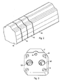
- Fig. 2 shows an extruded profile 44 from which the first three terminal plate blanks 45 are cut to length in an inventive method step.
- the extruded profile has a cross section that is the same throughout along its longitudinal axis and is shaped according to the desired contour of the finished connection plate 2.
- complex subsequent processing steps for shaping the contour of the connection plate 2 can be omitted.
- the extruded profile 44 is cut to several connection plate blanks 45 of the same or different thickness or thickness. This makes it very easy to make connection plate blanks 45 for the production of connection plates 2 for different types of hydrostatic machines, especially for pumps of different performance.
- connection plate blanks 45 are separated from the extruded profile 44, for example by sawing or water jet cutting. Depending on the material of the extruded profile 44, the necessary accuracy and the desired quantities of the connection plates 2, other separation methods can be used, for example laser cutting or a burn-out.
- the terminal plate blanks 45 are separated at right angles to the longitudinal axis of the extruded profile 44, so that the two perpendicular to the longitudinal axis of the connection plate blanks 45 lying surfaces parallel.
- the connection plate blanks 45 can also be separated or cut to length from the extruded profile 44 by an oblique cut, whereby the connection plate blank 45 or the connection plate 2 is wedge-shaped or concave.
- the extruded profile 44 is preferably at least partially made of aluminum, iron or copper or a corresponding alloy.
- the extruded profile 44 is produced for example by casting or pressing.
- the extruded profile 44 is thus designed or manufactured, for example, as a continuous casting profile 44 or as an extruded profile 44.
- Fig. 3 shows an exemplary embodiment of a connection plate according to the invention 2.
- the connection plate 2 has been cut in a method step according to the invention first of the extruded profile 44 with a perpendicular to the longitudinal axis of the extruded profile 44 extending section of the extruded profile 44.
- the resulting connection plate blank 45 is further processed Service.
- the pressure channel 16D, the suction channel 16S and several other openings 46 which may be part of a screw, for example, introduced by drilling in the terminal plate blank 45.
- the connection line 38, the blind bore 19 and the channel 39 can be introduced into the connection plate blank 45.
- connection plate 2 produced by the method according to the invention can be produced very inexpensively and quickly in various thicknesses or thicknesses, so that there are great cost advantages over the manufacturing process known from the prior art.
Description
Die Erfindung betrifft die Anschlußplatte einer hydrostatischen Maschine, insbesondere einer Axialkolbenmaschine.The invention relates to the connection plate of a hydrostatic machine, in particular an axial piston machine.
Beispielsweise wird in der
Weiterhin ist aus der
Aus der
Herkömmlicherweise werden solche oben erwähnten Anschlußplatten aus einzeln zu plattenförmig gegossenen oder geschmiedeten Rohlingen gefertigt.Conventionally, such above-mentioned connection plates are made of individual slab-cast or forged blanks.
Nachteilig dabei ist die relativ kostenintensive Herstellung solcher plattenförmiger Halbzeuge mit vielen und energieintensiven Verarbeitungsschritten. Der Herstellungsaufwand, die Herstellungskosten und die Herstellungszeit der Anschlußplatte ist dadurch deutlich erhöht. Insbesondere die Dicke der Anschlußplatte kann nur durch hohen Aufwand im Herstellungsverfahren, beispielsweise durch eine neue Gießform oder ein neues Gesenk, verändert werden.The disadvantage here is the relatively costly production of such plate-shaped semi-finished products with many and energy-intensive processing steps. The production cost, the manufacturing cost and the production time of the connection plate is thereby significantly increased. In particular, the thickness of the connection plate can only be changed by high costs in the manufacturing process, for example by a new mold or a new die.
Es ist die Aufgabe der Erfindung eine Anschlußplatte zu beschreiben, die kostengünstig und mit geringem Aufwand gefertigt werden kann.It is the object of the invention to describe a connection plate, which can be manufactured inexpensively and with little effort.
Die Aufgabe wird erfindungsgemäß durch die Merkmale des Anspruchs 1 gelöst.The object is achieved by the features of claim 1.
Bei dem Herstellungsverfahren zur Herstellung einer Anschlußplatte wird der als Zwischenschritt zur Herstellung der Anschlußplatte entstehende Anschlußplatten-Rohling von einem Strangprofil abgelängt und nicht einzeln, wie in herkömmlichen Herstellungsverfahren, gegossen oder geschmiedet.In the manufacturing method of manufacturing a terminal plate, the terminal plate blank formed as an intermediate step for manufacturing the terminal plate is cut from an extruded profile and not individually cast or forged as in conventional manufacturing processes.
Die in den Unteransprüchen ausgeführten Maßnahmen betreffen vorteilhafte Weiterbildungen der erfindungsgemäßen Anschlußplatte.The measures carried out in the dependent claims relate to advantageous developments of the connection plate according to the invention.
Insbesondere ist es vorteilhaft, das Strangprofil durch Gießen oder Pressen herzustellen. Das Strangprofil kann dadurch besonders einfach und kostengünstig hergestellt werden.In particular, it is advantageous to produce the extruded profile by casting or pressing. The extruded profile can be made particularly simple and inexpensive.
Weiterhin ist es vorteilhaft, wenn das Strangprofil zumindest teilweise aus Aluminium, Kupfer oder Eisen besteht oder aus einer Legierung mit zumindest einem dieser Metalle. Die Anschlußplatte kann dadurch einfach mit den gewünschten Materialeigenschaften hergestellt werden.Furthermore, it is advantageous if the extruded profile consists at least partially of aluminum, copper or iron or of an alloy with at least one of these metals. The connection plate can thereby be easily manufactured with the desired material properties.
Weiterhin ist es vorteilhaft, wenn sich das Strangprofil im Querschnitt mit der Kontur der fertigen Anschlußplatte deckt. Der von dem Strangprofil abgelängte Anschlußplatten-Rohling muß in seiner Kontur dann nicht mehr nachbearbeitet werden.Furthermore, it is advantageous if the extruded profile covers in cross-section with the contour of the finished connection plate. The cut from the extruded connection plate blank must then not be reworked in its contour.
Vorteilhaft ist es zudem, wenn das Strangprofil zu zumindest zwei Anschlußplatten-Rohlingen abgelängt wird. Dadurch wird das Herstellungsverfahren deutlich einfacher, da aus einem Strangprofil mehrere Anschlußplatten-Rohlinge in einfacher Weise erzeugt werden können.It is also advantageous if the extruded profile is cut to at least two terminal board blanks. As a result, the manufacturing process is much easier, since a plurality of terminal plate blanks can be produced in a simple manner from an extruded profile.
Eine bevorzugte Ausführungsform der erfindungsgemäßen Anschlußplatte ist in der Zeichnung dargestellt und wird in der nachfolgenden Beschreibung näher erläutert. Es zeigen:
- Fig. 1
- eine schematisch dargestellte hydrostatische Maschine mit Anschlußplatte nach dem Stand der Technik,
- Fig. 2
- ein Strangprofil mit drei abgelängten Anschlußplatten-Rohlingen zur Beschreibung des erfindungsgemäßen Herstellungsverfahrens und
- Fig. 3
- ein Ausführungsbeispiel einer erfindungsgemäßen Anschlußplatte.
- Fig. 1
- a schematically illustrated hydrostatic machine with connection plate according to the prior art,
- Fig. 2
- an extruded profile with three cut terminal block blanks to describe the manufacturing process of the invention and
- Fig. 3
- An embodiment of a connection plate according to the invention.
Bevor die erfindungsgemäße Anschlußplatte und das erfindungsgemäße Verfahren zur Herstellung der Anschlußplatte anhand der
Die in der
Die Schrägscheibe 3 ist als sogenannte Schwenkwiege mit halbzylindrischem Querschnitt ausgebildet und stützt sich mit zwei, mit gegenseitigem Abstand parallel zur Schwenkrichtung verlaufenden Lagerflächen unter hydrostatischer Entlastung an zwei entsprechend geformten Lagerschalen 8 ab, die an der Innenfläche der der Anschlußplatte 2 gegenüberliegenden Gehäuse-Stirnwand 9 befestigt sind. Die hydrostatische Entlastung erfolgt in bekannter Weise über Drucktaschen 10, die in den Lagerschalen 8 ausgebildet sind und über Anschlüsse 11 mit Druckmittel versorgt werden. Eine in einer Ausbuchtung einer zylindrischen Gehäusewandung 12 untergebrachte Stelleinrichtung 13 greift über einen sich in Richtung der Anschlußplatte 2 erstreckenden Arm 14 an der Schrägscheibe 3 an und dient zum Verschwenken derselben um eine zur Schwenkrichtung senkrechte Schwenkachse.The swash plate 3 is formed as a so-called pivoting cradle with a semi-cylindrical cross-section and is supported by two spaced parallel to the pivot direction bearing surfaces under hydrostatic discharge to two correspondingly shaped bearing
Der Steuerkörper 4 ist an der dem Gehäuse-Innenraum zugewandten Innenfläche der Anschlußplatte 2 befestigt und mit zwei durchgehenden Öffnungen 15 in Form von nierenförmigen Steuerschlitzen versehen, die über einen Druckkanal 16D bzw. Saugkanal 16S in der Anschlußplatte 2 an eine nicht gezeigte Druck- und Saugleitung angeschlossen sind. Der Druckkanal 16D weist einen kleineren Strömungsquerschnitt als der Saugkanal 16S auf. Die dem Gehäuse-Innenraum zugewandte und sphärisch ausgebildete Steuerfläche des Steuerkörpers 4 dient als Lagerfläche für die Zylindertrommel 6.The control body 4 is fixed to the housing interior facing the inner surface of the
Die Triebwelle 5 ragt durch eine Durchgangsbohrung in der Gehäuse-Stirnwand 9 in das Gehäuse 1 hinein und ist mittels eines Lagers 17 in dieser Durchgangsbohrung sowie mittels eines weiteren Lagers 18 in einem engeren Bohrungsabschnitt einer endseitig erweiterten Sackbohrung 19 in der Anschlußplatte 2 und einem an diesen engeren Bohrungsabschnitt angrenzenden Bereich einer zentrischen Durchgangsbohrung 20 im Steuerkörper 4 drehbar gelagert. Die Triebwelle 5 durchsetzt im Inneren des Gehäuses 1 weiterhin eine zentrische Durchgangsbohrung 21 in der Schrägscheibe 3, deren Durchmesser entsprechend dem größten Schwenkausschlag der Schrägscheibe 3 bemessen ist, sowie eine zentrische Durchgangsbohrung in der Zylindertrommel 6 mit zwei Bohrungsabschnitten.The
Einer dieser Bohrungsabschnitte ist in einer an der Zylindertrommel 6 angeformten, über deren der Schrägscheibe 3 zugewandte Stirnseite 22 hinausragenden hülsenförmigen Verlängerung 23 ausgebildet, über die die Zylindertrommel 6 mittels einer Keilnut-Verbindung 24 drehfest mit der Triebwelle 5 verbunden ist. Der verbleibende Bohrungsabschnitt ist mit konischem Verlauf ausgebildet. Er verjüngt sich ausgehend von seinem Querschnitt größten Durchmessers nahe dem ersten Bohrungsabschnitt bis zu seinem Querschnitt kleinsten Durchmessers nahe der am Steuerkörper 4 anliegenden Stirn- oder Lagerfläche der Zylindertrommel 6. Der von der Triebwelle 5 und diesem konischen Bohrungsabschnitt definierte ringförmige Raum ist mit dem Bezugszeichen 25 bezeichnet.One of these bore sections is integrally formed on the cylinder drum 6, via the Swash plate 3 facing
Die Zylindertrommel 6 weist allgemein axial verlaufende, abgestufte Zylinderbohrungen 26 auf, die gleichmäßig auf einem zur Triebwellenachse koaxialen Teilkreis angeordnet sind. Die Zylinderbohrungen 26 münden an der Zylindertrommel-Stirnseite 22 direkt und an der dem Steuerkörper 4 zugewandten Zylindertrommel-Lagerfläche über Mündungskanäle 27 auf dem gleichen Teilkreis wie die Steuerschlitze aus. In die an der Zylindertrommel-Stirnseite 22 direkt ausmündenden Zylinderbohrungsabschnitte größeren Durchmessers ist je eine Laufbuchse 28 eingesetzt. Die Zylinderbohrungen 26 einschließlich der Laufbuchsen 28 sind hier als Zylinder bezeichnet. Innerhalb dieser Zylinder verschiebbar angeordnete Kolben 29 sind an ihren der Schrägscheibe 3 zugewandten Enden mit Kugelköpfen 30 versehen, die in Gleitschuhen 31 gelagert und über diese an einer an der Schrägscheibe 3 befestigten ringförmigen Gleitscheibe 32 hydrostatisch gelagert sind. Jeder Gleitschuh 31 ist an seiner der Gleitscheibe 32 zugewandten Gleitfläche mit je einer nicht gezeigten Drucktasche versehen, die über eine Durchgangsbohrung 33 im Gleitschuh 31 an einen abgestuften axialen Durchgangskanal 34 im Kolben 29 angeschlossen und auf diese Weise mit dem vom Kolben 29 in der Zylinderbohrung 26 abgegrenzten Arbeitsraum des Zylinders verbunden ist. In jedem axialen Durchgangskanal 34 ist im Bereich des zugeordneten Kugelkopfes 30 eine Drossel ausgebildet. Ein mittels der Keilnut-Verbindung 24 axial verschiebbar auf der Triebwelle 5 angeordneter und durch eine Feder 35 in Richtung der Schrägscheibe 3 beaufschlagter Niederhalter 36 hält die Gleitschuhe 31 in Anlage an die Gleitscheibe 32.The cylinder drum 6 has generally axially extending, stepped
Der im Gehäuse-Innenraum von den darin aufgenommenen Bauteilen 3 bis 6 etc. nicht eingenommene Raum dient als Leckraum 37, der das im Betrieb der Axialkolbenmaschine durch sämtliche Spalte, wie zum Beispiel zwischen den Zylindern und den Kolben 29, dem Steuerkörper 4 und der Zylindertrommel 6, der Schrägscheibe 3 und der Gleitscheibe 32 sowie den Lagerschalen 8 etc., austretende Leckfluid aufnimmt.The space not occupied in the housing interior by the components 3 to 6 accommodated therein serves as a
Die Funktion der vorstehend beschriebenen Axialkolbenmaschine ist allgemein bekannt und in nachstehender Beschreibung bei Einsatz als Pumpe auf das wesentliche beschränkt.The function of the axial piston machine described above is well known and limited in the following description when used as a pump on the essential.
Die Axialkolbenmaschine ist für den Betrieb mit Öl als Fluid vorgesehen. Über die Triebwelle 5 wird die Zylindertrommel 6 mitsamt den Kolben 29 in Drehung versetzt. Wenn durch Betätigung der Stelleinrichtung 13 die Schrägscheibe 3 in eine Schrägstellung gegenüber der Zylindertrommel 6 verschwenkt ist, vollführen sämtliche Kolben 29 Hubbewegungen. Bei Drehung der Zylindertrommel 6 um 360° durchläuft jeder Kolben 29 einen Saug- und einen Kompressionshub, wobei entsprechende Ölströme erzeugt werden, deren Zu- und Abführung über die Mündungskanäle 27, die Steuerschlitze 15 und den Druck- und Saugkanal 16D, 16S erfolgen. Dabei läuft während des Kompressionshubs jedes Kolbens 29 Drucköl von dem betreffenden Zylinder über den axialen Durchgangskanal 34 und die Durchgangsbohrung 33 im zugeordneten Gleitschuh 31 in dessen Drucktasche und baut ein Druckfeld zwischen der Gleitscheibe 32 und dem jeweiligen Gleitschuh 31 auf, das als hydrostatisches Lager für Letzteren dient. Ferner wird Drucköl über die Anschlüsse 11 den Drucktaschen 10 in den Lagerschalen 8 zur hydrostatischen Abstützung der Schrägscheibe 3 zugeführt.The axial piston machine is intended for operation with oil as a fluid. About the
Der im dargestellten Ausführungsbeispiel vorhandene, aber im Rahmen der vorliegenden Erfindung keineswegs notwendige Kühlkreislauf 7.1 ist an den Leckraum 37 angeschlossen und umfaßt den konischen ringförmigen Raum 25 (sogenannter Leckfluid-Aufnahmeraum), die Durchgangsbohrung 20 im Steuerkörper 4, die Sackbohrung 19 (sogenannter weiterer Leckfluid-Aufnahmeraum), eine diesen mit dem Leckraum 37 verbindende Anschlußleitung 38, die in einer umlaufenden Rinne 39 in der Innenfläche der Anschlußplatte 2 ausmündet, sowie den Zylindern 26, 28 umlaufend zugeordnete Kühlbereiche, die über Zulaufkanäle 40 an den konischen ringförmigen Raum 25 angeschlossen sind und über Ablaufkanäle 41 an der zylindrischen Begrenzungsfläche 42 der Zylindertrommel 6 in den Leckraum 37 ausmünden. Sämtliche Zulaufkanäle 40 münden in den konischen ringförmigen Raum 25 an dessen Querschnitt größten Durchmessers ein und verlaufen ebenso wie sämtliche Ablaufkanäle 41 im wesentlichen radial durch die Zylindertrommel 6.The present in the illustrated embodiment, but in the context of the present invention by no means necessary cooling circuit 7.1 is connected to the
In der Ausgestaltung nach
Nachdem vorstehend eine übliche Axialkolbenmaschine beschrieben wurde, wird nun auf die erfindungsgemäßen Besonderheiten eingegangen.After a conventional axial piston machine has been described above, the features of the invention will now be discussed.
Die Anschlußplatten-Rohlinge 45 sind beispielsweise durch Sägen oder Wasserstrahlschneiden vom Strangprofil 44 abgetrennt. Je nach Material des Strangprofils 44, der notwendigen Genauigkeit und der gewünschten Stückzahlen der Anschlußplatten 2 können auch andere Trennverfahren angewandt werden, beispielsweise Laserschneiden oder ein Ausbrennverfahren. In dem in
Je nach erforderlicher Stückzahl der Anschlußplatten 2 und den gewünschten Materialeigenschaften, wird das Strangprofil 44 beispielsweise durch Gießen oder Pressen hergestellt. Das Strangprofil 44 ist folglich beispielsweise als Stranggußprofil 44 oder als Strangpreßprofil 44 ausgeführt bzw. hergestellt.Depending on the required number of connecting
Die durch das erfindungsgemäße Verfahren hergestellte Anschlußplatte 2 kann sehr kostengünstig und schnell auch in verschiedenen Stärken bzw. Dicken hergestellt werden, so daß sich gegenüber dem aus dem Stand der Technik bekannten Herstellungsverfahren große Kostenvorteile ergeben.The
Claims (4)
- Connecting plate (1) of a hydrostatic machine, the connecting plate (2) being produced from an extruded profile (44) and the connecting plate (2) being made from a connecting plate-blank (45) which has been cut off from the extruded profile (44), in cross-section, the contour of the extruded profile (44) and the contour of the connecting plate (2) being congruent and a blind bore (19) and a groove (39) and/or a connecting line (38) being introduced into the connecting plate (2)
characterised in that
a plurality of other apertures (46) are introduced into the connecting plate (1) by drilling, as constituents of a screw connection. - Connecting plate according to Claim 1,
characterised in that
the connecting plate (2) is produced from an extruded profile (44) which is produced by continuous casting or extruding. - Connecting plate according to Claim 1 or 2,
characterised in that
the connecting plate (2) is produced from an extruded profile (44) which consists at least partially of aluminium, iron or copper or an alloy with at least one of these metals. - Connecting plate according to one of Claims 1 to 3,
characterised in that
a connecting plate-blank (45) from which the connecting plate (2) is made, is cut off from the extruded profile (44) by sawing, laser cutting, water jet cutting or by a burning out method.
Applications Claiming Priority (2)
| Application Number | Priority Date | Filing Date | Title |
|---|---|---|---|
| DE10349318A DE10349318B4 (en) | 2003-10-23 | 2003-10-23 | Connection plate of a hydrostatic machine and method for producing the connection plate |
| EP04765920A EP1682777B1 (en) | 2003-10-23 | 2004-10-11 | Method for producing a connecting plate for a hydrostatic machine |
Related Parent Applications (1)
| Application Number | Title | Priority Date | Filing Date |
|---|---|---|---|
| EP04765920A Division EP1682777B1 (en) | 2003-10-23 | 2004-10-11 | Method for producing a connecting plate for a hydrostatic machine |
Publications (2)
| Publication Number | Publication Date |
|---|---|
| EP1757811A1 EP1757811A1 (en) | 2007-02-28 |
| EP1757811B1 true EP1757811B1 (en) | 2008-07-16 |
Family
ID=34484940
Family Applications (2)
| Application Number | Title | Priority Date | Filing Date |
|---|---|---|---|
| EP06023672A Expired - Fee Related EP1757811B1 (en) | 2003-10-23 | 2004-10-11 | Attachment plate for a hydrostatic piston machine and method of fabrication of said plate |
| EP04765920A Expired - Fee Related EP1682777B1 (en) | 2003-10-23 | 2004-10-11 | Method for producing a connecting plate for a hydrostatic machine |
Family Applications After (1)
| Application Number | Title | Priority Date | Filing Date |
|---|---|---|---|
| EP04765920A Expired - Fee Related EP1682777B1 (en) | 2003-10-23 | 2004-10-11 | Method for producing a connecting plate for a hydrostatic machine |
Country Status (4)
| Country | Link |
|---|---|
| US (1) | US20090013864A1 (en) |
| EP (2) | EP1757811B1 (en) |
| DE (3) | DE10349318B4 (en) |
| WO (1) | WO2005042975A1 (en) |
Families Citing this family (11)
| Publication number | Priority date | Publication date | Assignee | Title |
|---|---|---|---|---|
| DE102006003259A1 (en) * | 2006-01-19 | 2007-07-26 | Behr Thermot-Tronik Gmbh | Method for producing valve housings and valve housings |
| DE102006004383A1 (en) * | 2006-01-31 | 2007-08-02 | BSH Bosch und Siemens Hausgeräte GmbH | High level integrated cooking arrangement comprises a door with an upper side equipped with a pinching protection decorative part for testing the position of objects at a sufficient distance from a limiting device of a cooking chamber |
| DE102010013008A1 (en) | 2009-04-09 | 2010-10-14 | Robert Bosch Gmbh | Hydraulic axial piston machine with a connection plate |
| DE102009026417A1 (en) * | 2009-05-22 | 2010-12-02 | Robert Bosch Gmbh | Pump housing of a motor vehicle hydraulic unit |
| DE102010048073A1 (en) * | 2010-04-16 | 2011-10-20 | Robert Bosch Gmbh | Machine housing of a hydraulic machine |
| DE102010062270A1 (en) * | 2010-12-01 | 2012-06-06 | Robert Bosch Gmbh | Block-shaped pump housing of a vehicle brake system and method for its production |
| DE102012221135A1 (en) * | 2012-11-20 | 2014-05-22 | Robert Bosch Gmbh | Method for producing a valve device and corresponding valve device |
| DE102014217143A1 (en) * | 2014-08-28 | 2016-03-03 | Robert Bosch Gmbh | Cylinder drum for a hydrostatic axial piston unit |
| US20200232450A9 (en) * | 2015-09-29 | 2020-07-23 | Kerr Machine Co. | Multi-Piece Fluid End |
| DE102018205884A1 (en) * | 2018-04-18 | 2019-10-24 | Robert Bosch Gmbh | Axial piston machine with pressure relief in the Durchtriebsraum |
| CN110315283B (en) * | 2019-05-09 | 2021-09-24 | 泰州市创新电子有限公司 | Production method of integrated aluminum-extruded aluminum bracket |
Family Cites Families (9)
| Publication number | Priority date | Publication date | Assignee | Title |
|---|---|---|---|---|
| US4782738A (en) * | 1985-09-18 | 1988-11-08 | Gast Manufacturing Corporation | Compressor with adjustable head clearance |
| US4978284A (en) * | 1990-03-01 | 1990-12-18 | Cook James E | Double acting simplex plunger pump |
| US5173039A (en) * | 1991-09-27 | 1992-12-22 | Cook James E | Double acting simplex plunger pump |
| DE4423023C2 (en) * | 1994-06-30 | 1998-07-09 | Brueninghaus Hydromatik Gmbh | Axial piston machine with a cooling circuit for the cylinders and pistons |
| DE29614204U1 (en) * | 1996-08-16 | 1996-10-02 | Kuhnke Gmbh Kg H | Valve body |
| DE19643389C1 (en) * | 1996-10-21 | 1998-01-02 | Brueninghaus Hydromatik Gmbh | Axial piston machine with adjustable control plate |
| DE19914268C2 (en) * | 1999-03-29 | 2002-02-28 | Brueninghaus Hydromatik Gmbh | Axial piston machine and control body for an axial piston machine |
| DE102004043897A1 (en) * | 2004-03-09 | 2005-09-29 | Brueninghaus Hydromatik Gmbh | Drive system for utility vehicles has first and second drive shaft, to which cylinder drum of hydrostatic piston machine is fastened, piston stroke adjusting system and clutch being connected to common control inlet |
| DE102006021570A1 (en) * | 2006-04-10 | 2007-10-18 | Robert Bosch Gmbh | Hydrostatic piston machine with rotating control disc |
-
2003
- 2003-10-23 DE DE10349318A patent/DE10349318B4/en not_active Expired - Fee Related
-
2004
- 2004-10-11 DE DE502004003992T patent/DE502004003992D1/en active Active
- 2004-10-11 EP EP06023672A patent/EP1757811B1/en not_active Expired - Fee Related
- 2004-10-11 WO PCT/EP2004/011350 patent/WO2005042975A1/en active IP Right Grant
- 2004-10-11 DE DE502004007640T patent/DE502004007640D1/en active Active
- 2004-10-11 EP EP04765920A patent/EP1682777B1/en not_active Expired - Fee Related
- 2004-10-11 US US10/577,001 patent/US20090013864A1/en not_active Abandoned
Also Published As
| Publication number | Publication date |
|---|---|
| EP1682777A1 (en) | 2006-07-26 |
| DE10349318A1 (en) | 2005-05-25 |
| DE502004007640D1 (en) | 2008-08-28 |
| US20090013864A1 (en) | 2009-01-15 |
| WO2005042975A1 (en) | 2005-05-12 |
| DE10349318B4 (en) | 2006-10-05 |
| DE502004003992D1 (en) | 2007-07-12 |
| EP1682777B1 (en) | 2007-05-30 |
| EP1757811A1 (en) | 2007-02-28 |
Similar Documents
| Publication | Publication Date | Title |
|---|---|---|
| DE3404056C2 (en) | ||
| EP0767864B1 (en) | Axial piston engine with a cooling circuit for the cylinders and pistons | |
| EP1757811B1 (en) | Attachment plate for a hydrostatic piston machine and method of fabrication of said plate | |
| EP1704329B1 (en) | Piston for axial piston engine with inclined axes, and method for producing one such piston | |
| WO2007140868A1 (en) | Axial piston machine having a hydrostatic support of the hold-down | |
| DE3018711A1 (en) | AXIAL PISTON PUMP WITH PUMP INLET | |
| EP1475518A2 (en) | Bushing for a hydraulic valve | |
| WO2009124745A1 (en) | Flow-optimized cylinder drum for hydrostatic piston engines | |
| DE19528910C2 (en) | Swash plate compressor | |
| DE19802461C2 (en) | Coolant compressor | |
| EP0963506B1 (en) | Hydrostatic machine piston | |
| DE3725411C2 (en) | ||
| EP1427914B1 (en) | Hydrostatic machine with compensated sleeves | |
| DE102004007933B3 (en) | Axial piston engine and associated control system to dampen peak gas flow impulses by an inertia regulation passage | |
| WO2008074499A1 (en) | Hollow piston for an axial piston machine | |
| EP1588051B1 (en) | Piston machine with shaft and antifriction bearing | |
| DE10347085B3 (en) | Hydrostatic piston machine with two hydraulic circuits | |
| DE4039926C2 (en) | Axial piston pump, especially for water high-pressure cleaners | |
| DE19803860C2 (en) | Coolant compressor | |
| DE19815614A1 (en) | Axial piston machine with hydrostatic relief of cylinders | |
| EP0943798B1 (en) | Axial piston machine with hydrostatic relief of the cylinder bores | |
| DE102018205884A1 (en) | Axial piston machine with pressure relief in the Durchtriebsraum | |
| EP1561031B1 (en) | Axial piston machine, swash-plate and method for producing a swash-plate | |
| DE102007051935A1 (en) | Hydraulic actuation device for e.g. retractable hard-top, of opening in bodywork of motor vehicle i.e. passenger car, has circular bearing surface formed eccentrically such that length of each piston is larger than diameter of piston | |
| DE102022200140A1 (en) | Axial piston machine with at least partially machined pre-compression chambers |
Legal Events
| Date | Code | Title | Description |
|---|---|---|---|
| PUAI | Public reference made under article 153(3) epc to a published international application that has entered the european phase |
Free format text: ORIGINAL CODE: 0009012 |
|
| 17P | Request for examination filed |
Effective date: 20061114 |
|
| AC | Divisional application: reference to earlier application |
Ref document number: 1682777 Country of ref document: EP Kind code of ref document: P |
|
| AK | Designated contracting states |
Kind code of ref document: A1 Designated state(s): AT BE BG CH CY CZ DE DK EE ES FI FR GB GR HU IE IT LI LU MC NL PL PT RO SE SI SK TR |
|
| 17Q | First examination report despatched |
Effective date: 20070704 |
|
| AKX | Designation fees paid |
Designated state(s): DE FR GB IT SE |
|
| GRAP | Despatch of communication of intention to grant a patent |
Free format text: ORIGINAL CODE: EPIDOSNIGR1 |
|
| GRAS | Grant fee paid |
Free format text: ORIGINAL CODE: EPIDOSNIGR3 |
|
| GRAA | (expected) grant |
Free format text: ORIGINAL CODE: 0009210 |
|
| AC | Divisional application: reference to earlier application |
Ref document number: 1682777 Country of ref document: EP Kind code of ref document: P |
|
| AK | Designated contracting states |
Kind code of ref document: B1 Designated state(s): DE FR GB IT SE |
|
| REG | Reference to a national code |
Ref country code: GB Ref legal event code: FG4D Free format text: NOT ENGLISH |
|
| REF | Corresponds to: |
Ref document number: 502004007640 Country of ref document: DE Date of ref document: 20080828 Kind code of ref document: P |
|
| REG | Reference to a national code |
Ref country code: SE Ref legal event code: TRGR |
|
| PLBE | No opposition filed within time limit |
Free format text: ORIGINAL CODE: 0009261 |
|
| STAA | Information on the status of an ep patent application or granted ep patent |
Free format text: STATUS: NO OPPOSITION FILED WITHIN TIME LIMIT |
|
| 26N | No opposition filed |
Effective date: 20090417 |
|
| PGFP | Annual fee paid to national office [announced via postgrant information from national office to epo] |
Ref country code: FR Payment date: 20101109 Year of fee payment: 7 |
|
| PGFP | Annual fee paid to national office [announced via postgrant information from national office to epo] |
Ref country code: IT Payment date: 20101028 Year of fee payment: 7 Ref country code: GB Payment date: 20101021 Year of fee payment: 7 Ref country code: SE Payment date: 20101021 Year of fee payment: 7 |
|
| GBPC | Gb: european patent ceased through non-payment of renewal fee |
Effective date: 20111011 |
|
| REG | Reference to a national code |
Ref country code: SE Ref legal event code: EUG |
|
| REG | Reference to a national code |
Ref country code: FR Ref legal event code: ST Effective date: 20120629 |
|
| PG25 | Lapsed in a contracting state [announced via postgrant information from national office to epo] |
Ref country code: IT Free format text: LAPSE BECAUSE OF NON-PAYMENT OF DUE FEES Effective date: 20111011 Ref country code: GB Free format text: LAPSE BECAUSE OF NON-PAYMENT OF DUE FEES Effective date: 20111011 Ref country code: FR Free format text: LAPSE BECAUSE OF NON-PAYMENT OF DUE FEES Effective date: 20111102 |
|
| PG25 | Lapsed in a contracting state [announced via postgrant information from national office to epo] |
Ref country code: SE Free format text: LAPSE BECAUSE OF NON-PAYMENT OF DUE FEES Effective date: 20111012 |
|
| PGFP | Annual fee paid to national office [announced via postgrant information from national office to epo] |
Ref country code: DE Payment date: 20121217 Year of fee payment: 9 |
|
| REG | Reference to a national code |
Ref country code: DE Ref legal event code: R119 Ref document number: 502004007640 Country of ref document: DE Effective date: 20140501 |
|
| PG25 | Lapsed in a contracting state [announced via postgrant information from national office to epo] |
Ref country code: DE Free format text: LAPSE BECAUSE OF NON-PAYMENT OF DUE FEES Effective date: 20140501 |