EP1757214B1 - Encapsulated endoscope and encapsulated endoscope system - Google Patents
Encapsulated endoscope and encapsulated endoscope system Download PDFInfo
- Publication number
- EP1757214B1 EP1757214B1 EP05737179A EP05737179A EP1757214B1 EP 1757214 B1 EP1757214 B1 EP 1757214B1 EP 05737179 A EP05737179 A EP 05737179A EP 05737179 A EP05737179 A EP 05737179A EP 1757214 B1 EP1757214 B1 EP 1757214B1
- Authority
- EP
- European Patent Office
- Prior art keywords
- unit
- capsule endoscope
- illuminating
- timing
- image
- Prior art date
- Legal status (The legal status is an assumption and is not a legal conclusion. Google has not performed a legal analysis and makes no representation as to the accuracy of the status listed.)
- Not-in-force
Links
- 239000002775 capsule Substances 0.000 claims description 113
- 238000003384 imaging method Methods 0.000 claims description 68
- 230000008859 change Effects 0.000 claims description 9
- 230000007423 decrease Effects 0.000 claims description 5
- 238000005286 illumination Methods 0.000 abstract description 11
- 230000000694 effects Effects 0.000 abstract description 2
- 230000002411 adverse Effects 0.000 abstract 1
- 230000001276 controlling effect Effects 0.000 abstract 1
- 230000001105 regulatory effect Effects 0.000 abstract 1
- 230000007246 mechanism Effects 0.000 description 21
- 230000000630 rising effect Effects 0.000 description 19
- 230000006870 function Effects 0.000 description 16
- 239000011159 matrix material Substances 0.000 description 6
- 230000008901 benefit Effects 0.000 description 5
- 230000003287 optical effect Effects 0.000 description 4
- 210000000056 organ Anatomy 0.000 description 4
- 230000005540 biological transmission Effects 0.000 description 3
- 238000001816 cooling Methods 0.000 description 3
- 238000010586 diagram Methods 0.000 description 2
- 230000008030 elimination Effects 0.000 description 2
- 238000003379 elimination reaction Methods 0.000 description 2
- 230000007613 environmental effect Effects 0.000 description 2
- 230000010354 integration Effects 0.000 description 2
- 238000009825 accumulation Methods 0.000 description 1
- 238000004364 calculation method Methods 0.000 description 1
- 230000000295 complement effect Effects 0.000 description 1
- 230000003247 decreasing effect Effects 0.000 description 1
- 238000003745 diagnosis Methods 0.000 description 1
- 238000000605 extraction Methods 0.000 description 1
- 238000001727 in vivo Methods 0.000 description 1
- 238000011503 in vivo imaging Methods 0.000 description 1
- 238000007689 inspection Methods 0.000 description 1
- 239000004973 liquid crystal related substance Substances 0.000 description 1
- 230000006386 memory function Effects 0.000 description 1
- 229910044991 metal oxide Inorganic materials 0.000 description 1
- 150000004706 metal oxides Chemical class 0.000 description 1
- 238000012986 modification Methods 0.000 description 1
- 230000004048 modification Effects 0.000 description 1
- 230000002572 peristaltic effect Effects 0.000 description 1
- 230000004044 response Effects 0.000 description 1
- 239000004065 semiconductor Substances 0.000 description 1
- 210000000813 small intestine Anatomy 0.000 description 1
- 210000002784 stomach Anatomy 0.000 description 1
Images


Classifications
-
- A—HUMAN NECESSITIES
- A61—MEDICAL OR VETERINARY SCIENCE; HYGIENE
- A61B—DIAGNOSIS; SURGERY; IDENTIFICATION
- A61B1/00—Instruments for performing medical examinations of the interior of cavities or tubes of the body by visual or photographical inspection, e.g. endoscopes; Illuminating arrangements therefor
- A61B1/04—Instruments for performing medical examinations of the interior of cavities or tubes of the body by visual or photographical inspection, e.g. endoscopes; Illuminating arrangements therefor combined with photographic or television appliances
- A61B1/041—Capsule endoscopes for imaging
-
- A—HUMAN NECESSITIES
- A61—MEDICAL OR VETERINARY SCIENCE; HYGIENE
- A61B—DIAGNOSIS; SURGERY; IDENTIFICATION
- A61B1/00—Instruments for performing medical examinations of the interior of cavities or tubes of the body by visual or photographical inspection, e.g. endoscopes; Illuminating arrangements therefor
- A61B1/04—Instruments for performing medical examinations of the interior of cavities or tubes of the body by visual or photographical inspection, e.g. endoscopes; Illuminating arrangements therefor combined with photographic or television appliances
-
- A—HUMAN NECESSITIES
- A61—MEDICAL OR VETERINARY SCIENCE; HYGIENE
- A61B—DIAGNOSIS; SURGERY; IDENTIFICATION
- A61B5/00—Measuring for diagnostic purposes; Identification of persons
- A61B5/0002—Remote monitoring of patients using telemetry, e.g. transmission of vital signals via a communication network
- A61B5/0031—Implanted circuitry
Definitions
- the present invention relates to a capsule endoscope that is inserted into a subject and picks up an image inside the subject, and to a capsule endoscope system for the same.
- a swallowable type capsule endoscope has been proposed in recent years.
- the capsule endoscope has an imaging function and a radio transmission function.
- the capsule endoscope travels through inside a body cavity, i.e., inside organs such as a stomach and a small intestine, and sequentially images inside the organs, while following peristaltic motion of the organs.
- Image data obtained inside a body by the capsule endoscope is sequentially transmitted to outside by radio transmission and stored in a memory provided outside, while the capsule endoscope travels through inside the body cavity.
- the subject can freely move during the period from when the capsule endoscope is swallowed until when the capsule endoscope is discharged, since the subject carries around a receiving device that has the radio transmission function and a memory function.
- a diagnosis can be made by a doctor or a nurse by displaying the image, which is based on the image data stored in the memory, of the organs on a display.
- the imaging function provided in the capsule endoscope is realized by, for example, a predetermined optical system and an imaging element such as a charge-coupled device (CCD). Specifically, the capsule endoscope acquires the image inside the subject by converting incident light focused by the optical system to electronic signals.
- CCD charge-coupled device
- Patent Document 1 Japanese Patent Application Laid-Open No. 2003-70728 (page 3, FIG. 1 )
- the conventional capsule endoscope system has a problem in which it is not easy to acquire a high quality subject interior image. Specifically, in the conventional capsule endoscope, it is difficult to acquire the high quality subject interior image due to difficulties in an adjustment of illumination luminance of the capsule endoscope and presence of noise components in acquired image data. Hereinafter, the problem is described in details.
- the conventional capsule endoscope has a problem in which it is not easy to adjust illumination light intensity of a light emitting diode (LED). Since the capsule endoscope needs to be miniaturized to a size insertable into the subject, it is preferred also to simplify a circuit installed in the capsule. Further, since the capsule endoscope needs to be driven for, for example, substantially 8 hours from when the capsule endoscope is inserted into the subject until when the capsule endoscope is discharged, a controlling circuit and the like provided in the capsule endoscope is required to have low power consumption.
- LED light emitting diode
- a photochromatic mechanism which is provided, for example, in a digital camera, in the capsule endoscope, so that it is necessary to provide a photochromatic mechanism specialized for the capsule endoscope.
- a photochromatic mechanism suitable for a use condition of the capsule endoscope does not necessarily exist.
- the dark current is a current component caused independent of incident light, and caused due to a mechanism of an imaging element such as the CCD.
- the noise components are mixed into an acquired image data corresponding to an amount of the dark current.
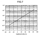
- FIG. 7 is a schematic graph of one example of temperature dependency of the dark current. As shown in FIG. 7 , strength of the dark current tends to monotonously increase as the temperature rises, and the noise components caused due to the dark current increase along with the rise in environmental temperature.
- the environmental temperature of the capsule endoscope becomes approximately 38°C (Celsius).
- the imaging element such as the CCD
- the dark current increases to substantially 3 to 4 times an amount under a room temperature (for example, 20°C). Therefore, when the imaging operation is performed by using the imaging element provided in the capsule endoscope, the amount of the dark current increases compared to when a normal imaging device is used, and the quality of the image is largely affected.
- a configuration in which an imaging is performed while cooling the CCD to eliminate the influence of the dark current has been proposed, and some have already put the configuration into practical use.
- US 2002/158976 discloses an imaging device having an in vivo CMOS image sensor, an illumination source, and a controller.
- the controller controls the illumination source to illuminate for a first period, and to be shut off for a subsequent period. Pixels of an image sensor are illuminated simultaneously in an illumination period. After the illumination period, the pixels are exposed to a dark period, in which only integration of dark signal noise occurs. During the dark period the pixels are successively read out and reset.
- each pixel in the image sensor has the same amount of dark signal integration (i.e., a constant "baseline” of dark noise) such that the dark signal noise is more constant, thereby reducing image distortion.
- WO 2003/009739 discloses a device for operating an in-vivo imaging device, wherein the illumination produced by the device may be varied in intensity and/or duration according to the amount of illumination which is reflected back to the device. When an amount of sensed illumination is larger than a threshold value, power to an LED device is terminated to cease operation of the LED.
- the present invention is provided in view of the foregoing, and an object of the present invention is to realize a capsule endoscope and a capsule endoscope system that can acquire a high quality image.
- a capsule endoscope as set forth in claim 1 is provided.
- the capsule endoscope is inserted into a subject and picks up an image inside the subject, and includes an illuminating unit that illuminates an interior surface of the subject with illuminating light, an imaging unit that generates an electronic signal corresponding to incident light and outputs the electronic signal generated, a noise canceller that eliminates noise charges, which are caused due to dark current and accumulated in the imaging unit, and a timing controller that controls driving timing of the noise canceller so that the driving timing lays within a period after the imaging unit finishes an output operation of the electronic signals and before the illuminating unit starts to emit the illuminating light.
- the capsule endoscope has the timing controller that drive the driving timing of the noise canceller during the period after when the output operation of the imaging unit is finished and before when the emission of the illuminating light is started. Consequently, the noise components caused due to the dark current can be eliminated without negatively affecting output operation of the electronic signals and generation of the electronic signals caused by the incident light.
- the timing controller performs a controlling operation so as to match driving starting timing of the illuminating unit with driving stopping timing of the noise canceller.
- the capsule endoscope includes a comparing unit that compares a predetermined reference luminance with a luminance of the image picked up by the imaging unit, and a light-emission-amount adjustment unit that adjusts an emission amount of the illuminating light output from the illuminating unit based on a comparison result of the comparing unit.
- the comparing unit derives a magnitude correlation between the image luminance and the reference luminance
- the light-emission-amount adjustment unit adjusts a driving period of the illuminating unit so as to decrease the driving period by a predetermined time when the image luminance exceeds the reference luminance, and adjusts the driving period of the illuminating unit so as to increase the driving period by a predetermined time when the image luminance is below the reference luminance.
- the timing controller maintains driving stopping timing of the illuminating unit fixed and changes driving starting timing of the illuminating unit, when a driving period of the illuminating unit is adjusted by the light-emission-amount adjustment unit.
- a capsule endoscope system includes a capsule endoscope and a receiving device.
- the capsule endoscope is inserted into a subject and picks up an image inside the subject as well as radio transmits radio signals including image data to outside.
- the receiving device receives the radio signals transmitted from the capsule endoscope.
- the receiving device includes a receiving antenna unit that receives the radio signal transmitted from the capsule endoscope, and an external device that performs a predetermined processing on the radio signals received by the receiving antenna unit.
- the capsule endoscope includes an illuminating unit that illuminates an interior surface of the subject with illuminating light, an imaging unit that includes a photoelectric transducer and outputs an electronic signal corresponding to incident light, a noise canceller that eliminates noise charges which are caused due to dark current and accumulated in the imaging unit, a timing controller that controls driving timing of the noise canceller so that the driving timing lays within a period after the imaging unit finishes an output operation of the electronic signal and before the illuminating unit starts to emit the illuminating light, and a radio unit that transmits the radio signal including the image data picked up by the imaging unit to outside.
- the capsule endoscope system further includes a comparing unit that compares predetermined reference luminance with luminance of an image picked up by the imaging unit, and a light-emission-amount adjustment unit that adjusts an emission amount of the illuminating light output from the illuminating unit based on a comparison result by the comparing unit, wherein the timing controller maintains a driving stopping timing of the illuminating unit fixed and changes the driving starting timing of the illuminating unit when a driving period of the illuminating unit is adjusted by the light-emission-amount adjustment unit, while controlling so as to match driving starting timing of the illuminating unit with driving stopping timing of the noise canceller.
- the capsule endoscope according to the present invention has a timing controller that sets driving timing of a noise canceller to a point during a period after when an output operation of an imaging unit is finished and before when emission of illuminating light is started, and the capsule endoscope system for the same. Consequently, noise components caused due to dark current can be eliminated without negatively affecting an output operation of electronic signals and generation of electronic signals caused by incident light.
- FIG. 1 is a schematic drawing of an overall configuration of the capsule endoscope system according to the present embodiment.
- the capsule endoscope system according to the present embodiment has a capsule endoscope 2, a receiving device 3, a display device 4, and a portable recording medium 5.
- the capsule endoscope 2 is inserted into a subject 1 to pick up a subject interior image, and radio transmits a picked up data to outside.
- the receiving device 3 detects a position of the capsule endoscope 2 inside the subject 1.
- the display device 4 displays contents of image data received by the receiving device 3.
- the portable recording medium 5 transfers information between the receiving device 3 and the display device 4.
- the display device 4 serves to display the subject interior image picked up by the capsule endoscope 2, and the display device 4 has a configuration such as a work station displaying the image based on data acquired through the portable recording medium 5.
- the display device 4 may directly display the image by a cathode ray tube (CRT) display, a liquid crystal display, and the like, or may output the image to other medium such as a printer and the like.
- CTR cathode ray tube
- the portable recording medium 5 is detachable with respect to an external device 8 described later and the display device 4, and the portable recording medium 5 is capable of outputting and recording the information when the portable recording medium 5 is attached to the external device 8 or the display device 4. Specifically, while the capsule endoscope 2 travels inside the subject 1, the portable recording medium 5 is attached to the external device 8 and records the information related to the position of the capsule endoscope 2. After the capsule endoscope 2 is discharged from the subject 1, the portable recording medium 5 is removed from the external device 8 and attached to the display device 4, and the recorded data is read by the display device 4.
- the subject 1 can freely move while the capsule endoscope 2 travels inside the subject 1 since the data are transferred between the external device 8 and the display device 4 by the portable recording medium 5 such as a Compact Flash (registered trademark) memory and the like.
- the portable recording medium 5 such as a Compact Flash (registered trademark) memory and the like.
- the receiving device 3 serves to receive the image data radio transmitted from the capsule endoscope 2, and to record the image data in the portable recording medium 5 after performing predetermined processing, if necessary, on the image data.
- the receiving device 3 has receiving antennas 7a to 7h and the external device 8, and receives radio signals, which are transmitted from the capsule endoscope 2, through any of the receiving antennas 7a to 7h as well as outputs the image data to the portable recording medium 5 after performing a processing such as an extraction of the image data from the radio signals.
- the capsule endoscope 2 will be described.
- the capsule endoscope 2 has a capsule-like exterior shape shown in FIG. 1 , and is formed with predetermined elements arranged inside the capsule.
- the capsule that forms the capsule endoscope 2 may be a spheroid.
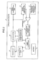
- FIG. 2 is a block diagram of an interior configuration of the capsule endoscope 2.
- the capsule endoscope 2 has a fist mechanism that picks up the subject interior image and the like, a second mechanism that adjusts intensity of the illuminating light when the subject interior image is picked up, and a third mechanism that determines driving timing of each element provided in the capsule endoscope 2.
- a fist mechanism that picks up the subject interior image and the like
- a second mechanism that adjusts intensity of the illuminating light when the subject interior image is picked up
- a third mechanism that determines driving timing of each element provided in the capsule endoscope 2.
- the capsule endoscope 2 has a mechanism that picks up the subject interior image and transmits the picked up subject interior image to outside, as the first mechanism.
- the capsule endoscope 2 has an illuminating unit 11, an imaging unit 12, an A/D converter 13, and a transmitting unit 15.
- the illuminating unit 11 illuminates inside the subject 1 with predetermined illuminating light.
- the imaging unit 12 receives reflected light of the illuminating light output from the illuminating unit 11, and outputs analog electronic signals corresponding to intensity of the incident light.
- the A/D converter 13 converts the analog electronic signals output from the imaging unit 12 into digital electronic signals.
- the transmitting unit 15 performs a necessary processing on the digital electronic signals output from the A/D converter 13, and radio transmits the processed digital electronic signals to outside.
- the illuminating unit 11 serves to output the illuminating light illuminating inside the subject 1, and the illuminating unit 11 allows the imaging unit 12 to pick up the subject interior image by outputting the illuminating light.
- the illuminating unit 11 is formed with, for example, an emission mechanism such as an LED and a driving controlling circuit of the emission mechanism.
- the illuminating unit 11 has a function of performing an emission operation at a time point set by a timing controller 20 described later.
- the imaging unit 12 serves to pick up the image inside the subject 1. Specifically, the imaging unit 12 has an optical system that focuses the incident light, and has a function of picking up the image inside the subject 1 by outputting the electronic signals corresponding to the intensity of the incident light focused by the optical system.
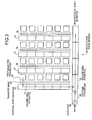
- FIG. 3 is a schematic drawing of a configuration of a solid-state image sensor 24 formed with a so called interline-type CCD element, and FIG. 3 is an example of an imaging element that forms the imaging unit 12.
- the solid-state image sensor 24 shown in FIG. 3 has plural photoelectric transducers 25, plural transfer gates 26, plural vertical shift registers 27, a horizontal shift register 28, a voltage converter 29, and an amplifier 30.
- the photoelectric transducers 25 are arranged in a matrix shape.
- the transfer gates 26 and the vertical shift registers 27 are extended in a column direction of the matrix of the photoelectric transducers 25, and arranged corresponding to number of rows.
- the horizontal shift register 28 is arranged at a downstream side of an output direction of charges of the vertical shift registers 27, and extended in a row direction.
- the voltage converter 29 converts charges output from the horizontal shift register 28 to voltage signals.
- the amplifier 30 amplifies the voltage signals output from the voltage converter 29.
- the number of rows and columns of the matrix of the photoelectric transducers 25 it is not necessary to restrictively interpret the number of rows and columns of the matrix of the photoelectric transducers 25 to the numbers of rows and columns shown in FIG. 3 , and practically, the numbers of rows and columns of the matrix are determined according to number of pixels of the picked up image.
- the photoelectric transducers 25 serve to generate electronic signals corresponding to intensity of the incident light.
- the photoelectric transducers 25 are formed with, for example, photodiodes, and have a function of accumulating charges corresponding to the incident light.
- the transfer gates 26 serve to control the charge transfer from the photoelectric transducers 25 to the vertical shift registers 27. Specifically, the transfer gates 26 have potentials that correspond to potentials applied by electrodes (not shown), and the charges stored in the photoelectric transducers 25 are transferred to the vertical shift registers 27 side according to the changes in the potentials.
- the vertical shift registers 27 serve to shift the charges output from the photoelectric transducers 25 in the column direction.
- the vertical shift registers 27 are configured by electrodes (not shown) controlling square well potentials 31 and potentials of the square well potentials 31 arranged according to the number of rows, and the vertical shift registers 27 have a function of shifting the charges transferred from the photoelectric transducers 25 in the column direction and outputting to the horizontal shift register 28, by sequentially changing the potentials of the square well potentials 31.
- the horizontal shift register 28 serves to transfer the charges in the row direction.
- the horizontal shift register 28 has square well potentials 32 corresponding to the number of rows of the matrix of the photoelectric transducers 25, and has a function of sequentially outputting the charges to the voltage converter 29 by sequentially controlling the potentials of the square well potentials 32.
- the transmitting unit 15 serves to radio transmit image data, which is obtained through the imaging by the imaging unit 12 and converted to digital signals by the A/D converter 13.
- the transmitting unit 15 has, for example, a transmitting circuit and a transmitting antenna.
- the transmitting circuit generates radio signals by performing a modulation processing and the like, if necessary, on the image data.
- the transmitting antenna serves to transmit the generated radio signals to outside.
- the capsule endoscope 2 has a mechanism of adjusting the emission amount of the illuminating unit 11, as the second mechanism.
- the capsule endoscope 2 has an image luminance deriving unit 16, a reference luminance information storage 17, a comparing unit 18, and a light-emission-amount adjustment unit 19.
- the image luminance deriving unit 16 derives image luminance of the image picked up by the imaging unit 12 based on the digital signals output from the A/D converter 13.
- the reference luminance information storage 17 acquires information related to predetermined reference luminance.
- the comparing unit 18 compares the image luminance with the reference luminance.
- the light-emission-amount adjustment unit 19 adjusts the emission amount of the illuminating unit 11 based on a comparison result of the comparing unit 18.
- the image luminance deriving unit 16 serves to derive the image luminance of the image picked up by the imaging unit 12.
- the image luminance deriving unit 16 has a function of deriving average luminance of a single pixel by adding luminance of each pixel constituting the picked up image data and dividing the added result by the number of pixels.
- the image luminance deriving unit 16 has, for example, a detecting circuit.
- the reference luminance information storage 17 stores information on preliminarily determined reference luminance. Specifically, the reference luminance information storage 17, for example, has a function of determining the reference luminance and storing information corresponding to the reference luminance. The reference luminance is set to a level that allows an operator to visually recognize the image content easily according to display ability of the display device 4.
- the reference luminance information storage 17 stores voltage value corresponding to the reference luminance as the reference luminance information, and specifically, the reference luminance information storage 17 has a constant voltage source that outputs the voltage value corresponding to the reference luminance.
- the comparing unit 18 serves to compare the image luminance derived at the image luminance deriving unit 16 with the reference luminance stored in the reference luminance information storage 17, and to output the comparison result to the light-emission-amount adjustment unit 19.
- An arbitrary relationship may be used as the comparison result output by the comparing unit 18 as long as the arbitrary relationship corresponds to a correlation between the image luminance and the reference luminance.
- a magnitude correlation between the image luminance and the reference luminance is simply used as the comparison result derived by the comparing unit 18.
- the light-emission-amount adjustment unit 19 serves to adjust light intensity of the illuminating light output from the illuminating unit 11 based on the comparison result acquired by the comparing unit 18. Specifically, the light-emission-amount adjustment unit 19 has a function of changing an output time of the illuminating light output from the illuminating unit 11 based on the comparison result derived by the comparing unit 18, and outputting information relating to the changed output time to the timing controller 20.
- the emission amount As a configuration to adjust the emission amount, it is proposed to adjust current supplied to the LED constituting the illuminating unit 11, for example, instead of adjusting the output time of the illuminating light.
- the above configuration or the like may be used to adjust the emission amount.
- emission luminance of a light-emitting element such as the LED provided in the illuminating unit 11 is not changed and the emission amount is adjusted by changing the emission time.
- An arbitrary algorithm may be employed to derive the output time of the illuminating light at the light-emission-amount adjustment unit 19 as long as the arbitrary algorithm adjusts the output time so as to decrease a difference between the reference luminance and the image luminance.
- the output time of the illuminating light is uniformly decreased by a predetermined time when the image luminance exceeds the reference luminance and the output time of the illuminating light is uniformly increased by a predetermined time when the image luminance is below the reference luminance, corresponding to the configuration in which the comparing unit 18 simply outputs the magnitude correlation.
- the capsule endoscope 2 has a mechanism that determines driving timing of each element, as the third mechanism.
- the capsule endoscope 2 has a timing controller 20 and a timing generator 21.
- the timing controller 20 controls operation timing of each element.
- the timing generator 21 supplies the driving timing and the like to the imaging unit 12 and the A/D converter 13 based on the control of the timing controller 20.
- the capsule endoscope 2 has a battery 22 that serves to supply driving power to each element.
- the timing generator 21 serves to supply the driving timings to the imaging unit 12 and the A/D converter 13 as well as to output a shutter pulse (reset pulse) for eliminating noise components caused by the dark current. Specifically, the timing generator 21 supplies the driving timings of the imaging unit 12 and the A/D converter 13 as well as supplies the shutter pulse to the imaging unit 12, based on a command from the timing controller 20.
- the timing generator 21 supplies the shutter pulse (reset pulse) to the imaging unit 12. Since the shutter pulse is supplied, predetermined potentials are, for example, supplied to the entire photoelectric transducers 25 and the charges accumulated by the dark current are discharged. Consequently, the timing generator 21 in the present embodiment functions as the noise canceller, and the timing generator 21 supplies the shutter pulse to the imaging unit 12 with predetermined timing commanded by the timing controller 20 to eliminate the noise components.
- the timing controller 20 serves to determine operation timings of the illuminating unit 11, the imaging unit 12, the A/D converter 13, the image luminance deriving unit 16, and the like based on the output from the light-emission-amount adjustment unit 19.
- the elements have a configuration in which the elements are driven according to the pulses output from the timing controller 20 or driven according to the pulses output from the timing generator 21 based on the control of the timing controller 20.
- the timing controller 20 controls the operation timings of the elements by controlling the rising edge and falling edge of the pulses.
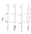
- FIG. 4 is a timing chart of supplying timings of the pulses controlled by the timing controller 20.
- a start pulse is generated under the control of the timing controller 20.
- the start pulse determines a starting of the imaging operation, i.e., starting time of an operation during which the charges accumulated in the photoelectric transducers 25 are output by the vertical shift registers 27 and the horizontal shift register 28.
- an interval between the start pulses defines an imaging period T necessary to acquire one image.
- the solid-state image sensor 24 transfers the charges accumulated in the photoelectric transducers 25 to the vertical shift registers 27 and outputs the analog electronic signals corresponding to the picked up image by operations of the vertical shift registers 27, the horizontal shift register 28, and the like.
- the A/D converter 13 performs the processing, and the image data formed by the digital electronic signals is generated.
- an illuminating unit driving pulse that defines the driving timing of the illuminating unit 11 is supplied in the late imaging period, i.e., right before the start pulse that defines the starting of the next imaging period is supplied.
- the time to start driving the illuminating unit 11 is set on the rising edge of the illuminating unit driving pulse, whereas the time to stop driving the illuminating unit 11 is set on the falling edge of the illuminating unit driving pulse.
- the illuminating unit 11 is operated according to the illuminating unit driving pulse, and in the example shown in FIG. 4 , the illuminating unit 11 outputs the illuminating light right before the start pulse is supplied, i.e., right before the transferring of the charges in the solid-state image sensor 24 is started.
- the shutter pulse is supplied.
- the shutter pulse is supplied at least after the imaging unit finishes data output operation and before the illuminating unit 11 starts to be driven, and in the example shown in FIG. 4 , the supplying timing of the shutter pulse is controlled so that the rising edge of the illuminating unit driving pulse coincides with the falling edge of the shutter pulse.
- the emission amount adjusting operation performed by the light-emission-amount adjustment unit 19 and a control performed by the timing controller 20 to change the pulse supplying timing based on the output from the light-emission-amount adjustment unit 19 will be described.
- the timing controller 20 basically controls the supply of the pulses shown in FIG. 4 , though the timing controller 20 also has a function of changing the supplying timings of respective pulses according to an output value of the light-emission-amount adjustment unit 19.
- the light-emission-amount adjustment unit 19 has a mechanism to adjust the emission amount by changing the output time of the illuminating light output from the illuminating unit 11.
- the timing controller 20 controls the changes in the supplying timings of the pulses based on the output of the light-emission-amount adjustment unit 19.
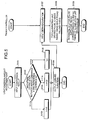
- FIG. 5 is a flowchart of the emission amount adjusting operation performed by the light-emission-amount adjustment unit 19, and the control performed by the timing controller 20 to change the pulse supplying timing subsequently to the emission amount adjusting operation.
- the light-emission-amount adjustment unit 19 inputs the comparison result derived by the comparing unit 18 (step S101), and determines the magnitude correlation between the image luminance and the reference luminance based on the comparison result (step S102).
- the pulse width t of the illuminating unit driving pulse are changed to t - ⁇ t (step S103).
- the timing controller 20 receives a specific value of the pulse width of the illuminating unit driving pulse output from the light-emission-amount adjustment unit 19 (step S107). Then, the timing controller 20 shifts the rising edge of the illuminating unit driving pulse while keeping the falling edge of the illuminating unit driving pulse at the current point so that the pulse width of the illuminating unit driving pulse comes to take the received value (step S108). Thereafter, the timing controller 20 changes the timing of the rise and the fall of the shutter pulse following the shift of the rising edge of the illuminating unit driving pulse so that the falling edge of the shutter pulse coincides with the rising edge of the illuminating unit driving pulse (step S109). Thus, in accordance with the change in the output time of the illuminating light from the illuminating unit 11, the timings of the operation pulses are adjusted and the adjusted timings are notified to each element, whereby the operation by the timing controller 20 finishes.
- FIG. 6 is a schematic drawing illustrating how the timings are changed in steps S108 and S109.
- the light intensity of the illuminating light output by the illuminating unit 11 is changed by adjusting the driving time of the illuminating unit 11; therefore, the pulse width of the illuminating unit driving pulse is changed. More specifically, however, three ways of changing the pulse width of the illuminating unit driving pulse may be considered; firstly to shift only the rising edge of the pulse; secondly to shift only the falling edge of the pulse; and thirdly to shift both the rising edge and the falling edge of the pulse.
- the present embodiment adjusts the pulse width at step S108 by shifting only the rising edge of the illuminating unit driving pulse and not the falling edge of the illuminating unit driving pulse. Since the timing controller 20 performs the controlling operation as described above, the start pulses remain to be supplied at fixed timing, in other words, the imaging unit output timing are kept supplied at fixed timing, independent of the change in the pulse width of the illuminating unit driving pulse.
- the pulse width of the shutter pulse is fixed regardless of the changes in the pulse width of the illuminating unit driving pulse; therefore, the timing of rise and fall of the shutter pulse is changed by an amount that is equivalent to the amount of change in the timing of rise of the illuminating unit driving pulse.
- the charges accumulated due to the dark current are eliminated in the capsule endoscope 2.
- the elimination of the charges prevents the noise components caused by the dark current from mixing into the picked up image data.
- the dark current is eliminated (in other words, the shutter pulse is supplied) at least after the imaging unit finishes supplying an output and before the illuminating unit driving pulse is supplied in each imaging period.
- a reason for setting the aforementioned timing is described hereinafter. It is not preferred from perspective of acquiring a high quality image data to supply the shutter pulse after the illuminating unit driving pulse is supplied, since the charges generated corresponding to the incident light by the photoelectric transducers 25 are, together, eliminated.
- the shutter pulse is supplied before the illuminating unit driving pulse is supplied, and the noise components can be eliminated, without negatively affecting the charges corresponding to the incident light, by supplying the shutter pulse with the timing described above.
- the shutter pulse is generally formed with a high intensity pulse signal.
- the shutter pulses are supplied during the charge transfer by the vertical shift register 27 and the horizontal shift register 28 provided in the solid-state image sensor 24, i.e., if the shutter pulses are supplied during the output of analog electronic signals from the imaging unit 12, the shutter pulse might negatively affect the transfer of the charges. Therefore, in the present embodiment, the shutter pulse is supplied after the output of the analog electronic signals from the imaging unit 12 is finished.
- the noise components can be eliminated without negative influence on the transfer of the charges.
- the supplying timing of the shutter pulse is controlled so that the shutter pulse is supplied right before the illuminating unit driving pulse is supplied, and more preferably the timings are controlled so that the rising edge of the illuminating unit driving pulse coincides with the falling edge of the shutter pulse, as shown in FIGS. 4 and 6 .
- the capsule endoscope system according to the present embodiment has an advantage in which the noise components caused by the dark current can be more surely eliminated. Since the charges caused by the dark current are gradually accumulated over the entire imaging period, the noise components caused by the dark current are reaccumulated after the noise components are eliminated by supplying the shutter pulse once.
- the shutter pulse falls right before the timing of incidence of the light, which corresponds to the subject interior image, into the photoelectric transducer 25 (i.e., the timing the illuminating unit driving pulse is supplied), and more preferably the shutter pulse falls when the illuminating unit driving pulse rises.
- the photoelectric transducer 25 i.e., the timing the illuminating unit driving pulse is supplied
- the shutter pulse falls when the illuminating unit driving pulse rises.
- the capsule endoscope 2 has an advantage in which a high quality image data having luminance that is similar to the reference luminance can be acquired.
- the comparing unit 18 derives only the magnitude correlation between the image luminance and the reference luminance. Since only the magnitude correlation between the image luminance and the reference luminance is derived as the comparison result used by the light-emission-amount adjustment unit 19, the comparing unit 18 can be formed with a comparator using a so-called operational amplifier (op-amp), a resistor, and the like. Since the comparator has a simple configuration as well as power consumption thereof is suppressed to a low value, a problem such as an increase in size of the capsule endoscope 2 and an increase in power consumption therein can be prevented even if the comparator is installed in the capsule endoscope 2.
- op-amp operational amplifier
- the light-emission-amount adjustment unit 19 changes the output time of the illuminating light by a preliminarily determined time ( ⁇ t in the flowchart of FIG. 5 ) based on the magnitude correlation acquired by the comparing unit 18. As shown in the flowchart of FIG. 5 , the light-emission-amount adjustment unit 19 decreases the output time of the illuminating light by ⁇ t when the image luminance exceeds the reference luminance, and the light-emission-amount adjustment unit 19 increases the output time of the illuminating light by ⁇ t when the image luminance is below the reference luminance.
- the capsule endoscope 2 inserted into the subject 1 and picking up the subject interior image sufficiently endures practical use even if the aforementioned mechanism adjusts emission amount.
- the amount of the incident light inside the subject 1 generally changes continuously and gradually, instead of changing dynamically, for example, when the capsule endoscope 2 moves out of a room to the outside.
- the emission amount corresponding to the change of amount of the incident light can be derived without any problems from practical point of view.
- the timing controller 20 may also have a simple configuration. As shown in FIGS. 4 and 6 , the supplying timing of the start pulse is set so that the start pulse has a fixed period and the falling edge of the illuminating unit driving pulse is made to coincide with the rising edge of the start pulse. Even when the pulse width of the illuminating unit driving pulse is changed, the timing controller 20 maintains coincidence between the rising edge of the illuminating unit driving pulse and the falling edge of the shutter pulse while changing the rising edge of the illuminating unit driving pulse.
- the timing controller 20 can sufficiently perform a dynamic control based on the output value of the light-emission-amount adjustment unit 19 only by shifting the rising edge of the illuminating unit driving pulse.
- the supplying timing of the start pulse is always fixed, and the supplying timing is controlled independent of the output value of the light-emission-amount adjustment unit 19.
- the pulse width may be preliminarily fixed and the coincidence between the falling edge of the shutter pulse and the rising edge of the illuminating unit driving pulse may be preliminarily set as a condition.
- the timing controller 20 can control every timing of rises and falls of the driving pulses only by shifting the rising edge of the illuminating unit driving pulse. Therefore, in the capsule endoscope 2 according to the present embodiment, the controlling operation, which is performed to obtain the aforementioned advantages, of the timing controller 20 can be performed by a simple algorithm, and as a result, the capsule endoscope 2 has an advantage in which the timing controller 20 having a simple configuration and low power consumption can be used.
- the noise components may be eliminated by a configuration other than the configuration in which the timing generator 21 supplies the shutter pulse to eliminate the noise components.
- the pulse width of the illuminating unit driving pulse is changed unless the image luminance matches with the reference luminance.
- the pulse width of the illuminating unit driving pulse does not have to be changed when the luminance difference is less than or equal to a predetermined threshold, by contriving the configuration of the comparing unit 18.
- the CCD is used as shown in FIG. 3 as the solid-state image sensor constituting the imaging unit 12; however, the present invention is not limited thereto.
- a complementary metal oxide semiconductor (CMOS) may be used as the solid-state image sensor.
- the capsule endoscope may include any imaging element as long as the imaging element has the explicit noise components attributable to the dark current.
- CMOS complementary metal oxide semiconductor
- a capsule endoscope and a capsule endoscope system is useful for a capsule endoscope system and a capsule endoscope that is inserted into a subject and picks up an image inside the subject, and more particularly suitable for a capsule endoscope and a capsule endoscope system that are capable of acquiring a high quality image.
Landscapes
- Health & Medical Sciences (AREA)
- Life Sciences & Earth Sciences (AREA)
- Surgery (AREA)
- Engineering & Computer Science (AREA)
- General Health & Medical Sciences (AREA)
- Animal Behavior & Ethology (AREA)
- Pathology (AREA)
- Veterinary Medicine (AREA)
- Public Health (AREA)
- Biophysics (AREA)
- Biomedical Technology (AREA)
- Heart & Thoracic Surgery (AREA)
- Medical Informatics (AREA)
- Molecular Biology (AREA)
- Physics & Mathematics (AREA)
- Optics & Photonics (AREA)
- Nuclear Medicine, Radiotherapy & Molecular Imaging (AREA)
- Radiology & Medical Imaging (AREA)
- Computer Networks & Wireless Communication (AREA)
- Endoscopes (AREA)
Abstract
Applications Claiming Priority (2)
| Application Number | Priority Date | Filing Date | Title |
|---|---|---|---|
| JP2004139890A JP4555604B2 (ja) | 2004-05-10 | 2004-05-10 | カプセル型内視鏡およびカプセル型内視鏡システム |
| PCT/JP2005/008421 WO2005107573A1 (ja) | 2004-05-10 | 2005-05-09 | カプセル型内視鏡およびカプセル型内視鏡システム |
Publications (3)
| Publication Number | Publication Date |
|---|---|
| EP1757214A1 EP1757214A1 (en) | 2007-02-28 |
| EP1757214A4 EP1757214A4 (en) | 2009-08-12 |
| EP1757214B1 true EP1757214B1 (en) | 2012-07-18 |
Family
ID=35319992
Family Applications (1)
| Application Number | Title | Priority Date | Filing Date |
|---|---|---|---|
| EP05737179A Not-in-force EP1757214B1 (en) | 2004-05-10 | 2005-05-09 | Encapsulated endoscope and encapsulated endoscope system |
Country Status (5)
| Country | Link |
|---|---|
| US (1) | US7762947B2 (ja) |
| EP (1) | EP1757214B1 (ja) |
| JP (1) | JP4555604B2 (ja) |
| CN (1) | CN100450423C (ja) |
| WO (1) | WO2005107573A1 (ja) |
Families Citing this family (11)
| Publication number | Priority date | Publication date | Assignee | Title |
|---|---|---|---|---|
| KR100869499B1 (ko) * | 2006-04-28 | 2008-11-21 | 주식회사 인트로메딕 | 인체의 체강 내에서 획득한 이미지의 처리 방법, 이를 이용하는 캡슐형 내시경 및 캡슐형 내시경 시스템 |
| JP5096090B2 (ja) * | 2007-09-19 | 2012-12-12 | オリンパスメディカルシステムズ株式会社 | 生体内画像受信装置および生体内画像取得システム |
| JP2009136459A (ja) * | 2007-12-05 | 2009-06-25 | Hoya Corp | ノイズ除去システム、内視鏡プロセッサ、および内視鏡システム |
| JP5284846B2 (ja) * | 2009-03-30 | 2013-09-11 | オリンパス株式会社 | 生体内観察システム、該生体内観察システムの作動方法 |
| JP2010240104A (ja) * | 2009-04-03 | 2010-10-28 | Olympus Corp | 体内観察システム、該体内観察システムの駆動方法 |
| JP5534997B2 (ja) * | 2010-08-03 | 2014-07-02 | 富士フイルム株式会社 | 電子内視鏡システム |
| EP2662016A4 (en) * | 2011-01-28 | 2017-04-12 | Olympus Corporation | Capsule endoscope system |
| DE102011077123A1 (de) * | 2011-06-07 | 2012-12-13 | Siemens Ag | Untersuchungsvorrichtung zur Untersuchung eines Hohlraumes |
| CN103488026A (zh) * | 2013-09-05 | 2014-01-01 | 广东欧珀移动通信有限公司 | 调节摄像头补光灯亮度的方法和系统 |
| JP6028131B1 (ja) * | 2015-03-30 | 2016-11-16 | オリンパス株式会社 | カプセル型内視鏡システムおよび磁界発生装置 |
| KR101851724B1 (ko) * | 2017-09-05 | 2018-04-24 | 심한보 | 경구형 내시경 장치 |
Family Cites Families (18)
| Publication number | Priority date | Publication date | Assignee | Title |
|---|---|---|---|---|
| JPH01207032A (ja) * | 1988-02-16 | 1989-08-21 | Toshiba Corp | 内視鏡装置 |
| JPH01250918A (ja) * | 1988-03-31 | 1989-10-05 | Toshiba Corp | 内視鏡装置 |
| JPH0865578A (ja) * | 1994-08-24 | 1996-03-08 | Olympus Optical Co Ltd | 固体撮像装置 |
| JP3413084B2 (ja) * | 1997-11-20 | 2003-06-03 | キヤノン株式会社 | 放射線撮像装置及び撮像方法 |
| JPH11253397A (ja) * | 1998-03-09 | 1999-09-21 | Olympus Optical Co Ltd | 内視鏡装置 |
| JP2000193896A (ja) * | 1998-12-28 | 2000-07-14 | Asahi Optical Co Ltd | 内視鏡の光量制御装置 |
| US6654054B1 (en) * | 1999-11-02 | 2003-11-25 | Agilent Technologies, Inc. | Method and apparatus for canceling the effects of noise in an electronic signal |
| US7023479B2 (en) * | 2000-05-16 | 2006-04-04 | Canon Kabushiki Kaisha | Image input apparatus having addition and subtraction processing |
| JP2001340324A (ja) * | 2001-03-16 | 2001-12-11 | Toshiba Medical System Co Ltd | X線検出器及びそれを使ったx線診断装置 |
| US7616238B2 (en) * | 2001-03-29 | 2009-11-10 | Given Imaging Ltd. | Method for timing control of an image sensor |
| JP4166509B2 (ja) | 2001-06-20 | 2008-10-15 | オリンパス株式会社 | カプセル式内視鏡 |
| IL155046A (en) * | 2003-03-23 | 2013-12-31 | Given Imaging Ltd | Install in-body imaging capable of defining its location |
| US20030117491A1 (en) | 2001-07-26 | 2003-06-26 | Dov Avni | Apparatus and method for controlling illumination in an in-vivo imaging device |
| CN100341459C (zh) * | 2002-08-05 | 2007-10-10 | 中国人民解放军总医院 | 医用无线电胶囊 |
| JP3934506B2 (ja) * | 2002-08-06 | 2007-06-20 | オリンパス株式会社 | 撮像システムおよび画像処理プログラム |
| JP4390440B2 (ja) * | 2002-10-31 | 2009-12-24 | Hoya株式会社 | 内視鏡用自動調光装置および電子内視鏡装置 |
| JP4328125B2 (ja) * | 2003-04-25 | 2009-09-09 | オリンパス株式会社 | カプセル型内視鏡装置およびカプセル型内視鏡システム |
| JP4349856B2 (ja) * | 2003-07-07 | 2009-10-21 | Hoya株式会社 | 自動調光可能な電子内視鏡装置 |
-
2004
- 2004-05-10 JP JP2004139890A patent/JP4555604B2/ja not_active Expired - Fee Related
-
2005
- 2005-05-09 WO PCT/JP2005/008421 patent/WO2005107573A1/ja not_active Application Discontinuation
- 2005-05-09 CN CNB200580014701XA patent/CN100450423C/zh not_active Expired - Fee Related
- 2005-05-09 EP EP05737179A patent/EP1757214B1/en not_active Not-in-force
-
2006
- 2006-11-08 US US11/594,438 patent/US7762947B2/en not_active Expired - Fee Related
Also Published As
| Publication number | Publication date |
|---|---|
| JP2005319096A (ja) | 2005-11-17 |
| CN100450423C (zh) | 2009-01-14 |
| JP4555604B2 (ja) | 2010-10-06 |
| EP1757214A1 (en) | 2007-02-28 |
| WO2005107573A1 (ja) | 2005-11-17 |
| US20070073105A1 (en) | 2007-03-29 |
| US7762947B2 (en) | 2010-07-27 |
| CN1950018A (zh) | 2007-04-18 |
| EP1757214A4 (en) | 2009-08-12 |
Similar Documents
| Publication | Publication Date | Title |
|---|---|---|
| EP1757214B1 (en) | Encapsulated endoscope and encapsulated endoscope system | |
| EP1411818B1 (en) | Apparatus and method for controlling illumination or imager gain in an in-vivo imaging device | |
| US8866893B2 (en) | Imaging apparatus | |
| US20040199061A1 (en) | Apparatus and methods for in vivo imaging | |
| US20130050455A1 (en) | Endoscope apparatus | |
| US8574151B2 (en) | In-vivo information acquiring system and body-insertable apparatus | |
| US20090299138A1 (en) | Imaging apparatus and in-vivo image obtaining apparatus | |
| JP2004535878A5 (ja) | ||
| US20070115378A1 (en) | Fcc-compliant, movement artifact-free image sensor array with reduced lighting requirement | |
| JP2006524097A (ja) | 生体内撮像装置において光を制御するための装置および方法 | |
| KR100722901B1 (ko) | 내시경용 촬상 장치 | |
| EP2353491B1 (en) | Subject intra-corporeal introduction device and in-vivo information acquiring system | |
| JP2008183049A (ja) | 撮像装置、カプセル型内視カメラ | |
| US8830310B2 (en) | Capsule endoscope | |
| CN107534745B (zh) | 具有集成功率节约控制的图像传感器 | |
| JP4698938B2 (ja) | カプセル型内視鏡およびカプセル型内視鏡システム | |
| WO2022190256A1 (ja) | 被検体内情報取得装置、検査システム、制御方法およびプログラム | |
| JP2005073885A (ja) | 被検体内導入装置および無線型被検体内情報取得システム | |
| JP5896877B2 (ja) | 調光装置 | |
| JP2010082224A (ja) | 撮像装置 |
Legal Events
| Date | Code | Title | Description |
|---|---|---|---|
| PUAI | Public reference made under article 153(3) epc to a published international application that has entered the european phase |
Free format text: ORIGINAL CODE: 0009012 |
|
| 17P | Request for examination filed |
Effective date: 20061108 |
|
| AK | Designated contracting states |
Kind code of ref document: A1 Designated state(s): DE FR GB |
|
| DAX | Request for extension of the european patent (deleted) | ||
| RBV | Designated contracting states (corrected) |
Designated state(s): DE FR GB |
|
| A4 | Supplementary search report drawn up and despatched |
Effective date: 20090714 |
|
| 17Q | First examination report despatched |
Effective date: 20091113 |
|
| REG | Reference to a national code |
Ref country code: DE Ref legal event code: R079 Ref document number: 602005035216 Country of ref document: DE Free format text: PREVIOUS MAIN CLASS: A61B0001000000 Ipc: A61B0005000000 |
|
| GRAP | Despatch of communication of intention to grant a patent |
Free format text: ORIGINAL CODE: EPIDOSNIGR1 |
|
| RIC1 | Information provided on ipc code assigned before grant |
Ipc: A61B 1/04 20060101ALI20120203BHEP Ipc: A61B 5/00 20060101AFI20120203BHEP |
|
| GRAS | Grant fee paid |
Free format text: ORIGINAL CODE: EPIDOSNIGR3 |
|
| GRAA | (expected) grant |
Free format text: ORIGINAL CODE: 0009210 |
|
| AK | Designated contracting states |
Kind code of ref document: B1 Designated state(s): DE FR GB |
|
| REG | Reference to a national code |
Ref country code: GB Ref legal event code: FG4D |
|
| REG | Reference to a national code |
Ref country code: DE Ref legal event code: R096 Ref document number: 602005035216 Country of ref document: DE Effective date: 20120913 |
|
| PLBE | No opposition filed within time limit |
Free format text: ORIGINAL CODE: 0009261 |
|
| STAA | Information on the status of an ep patent application or granted ep patent |
Free format text: STATUS: NO OPPOSITION FILED WITHIN TIME LIMIT |
|
| 26N | No opposition filed |
Effective date: 20130419 |
|
| REG | Reference to a national code |
Ref country code: DE Ref legal event code: R097 Ref document number: 602005035216 Country of ref document: DE Effective date: 20130419 |
|
| GBPC | Gb: european patent ceased through non-payment of renewal fee |
Effective date: 20130509 |
|
| REG | Reference to a national code |
Ref country code: FR Ref legal event code: ST Effective date: 20140131 |
|
| PG25 | Lapsed in a contracting state [announced via postgrant information from national office to epo] |
Ref country code: GB Free format text: LAPSE BECAUSE OF NON-PAYMENT OF DUE FEES Effective date: 20130509 |
|
| PG25 | Lapsed in a contracting state [announced via postgrant information from national office to epo] |
Ref country code: FR Free format text: LAPSE BECAUSE OF NON-PAYMENT OF DUE FEES Effective date: 20130531 |
|
| PGFP | Annual fee paid to national office [announced via postgrant information from national office to epo] |
Ref country code: DE Payment date: 20160504 Year of fee payment: 12 |
|
| REG | Reference to a national code |
Ref country code: DE Ref legal event code: R119 Ref document number: 602005035216 Country of ref document: DE |
|
| PG25 | Lapsed in a contracting state [announced via postgrant information from national office to epo] |
Ref country code: DE Free format text: LAPSE BECAUSE OF NON-PAYMENT OF DUE FEES Effective date: 20171201 |