EP1756601B1 - Method and structure to develop a test program for semiconductor integrated circuits - Google Patents
Method and structure to develop a test program for semiconductor integrated circuits Download PDFInfo
- Publication number
- EP1756601B1 EP1756601B1 EP05743229A EP05743229A EP1756601B1 EP 1756601 B1 EP1756601 B1 EP 1756601B1 EP 05743229 A EP05743229 A EP 05743229A EP 05743229 A EP05743229 A EP 05743229A EP 1756601 B1 EP1756601 B1 EP 1756601B1
- Authority
- EP
- European Patent Office
- Prior art keywords
- test
- file
- pattern
- plan
- header
- Prior art date
- Legal status (The legal status is an assumption and is not a legal conclusion. Google has not performed a legal analysis and makes no representation as to the accuracy of the status listed.)
- Expired - Lifetime
Links
Images


Classifications
-
- G—PHYSICS
- G06—COMPUTING OR CALCULATING; COUNTING
- G06F—ELECTRIC DIGITAL DATA PROCESSING
- G06F11/00—Error detection; Error correction; Monitoring
- G06F11/22—Detection or location of defective computer hardware by testing during standby operation or during idle time, e.g. start-up testing
- G06F11/26—Functional testing
-
- G—PHYSICS
- G01—MEASURING; TESTING
- G01R—MEASURING ELECTRIC VARIABLES; MEASURING MAGNETIC VARIABLES
- G01R31/00—Arrangements for testing electric properties; Arrangements for locating electric faults; Arrangements for electrical testing characterised by what is being tested not provided for elsewhere
- G01R31/28—Testing of electronic circuits, e.g. by signal tracer
- G01R31/317—Testing of digital circuits
- G01R31/3181—Functional testing
- G01R31/3183—Generation of test inputs, e.g. test vectors, patterns or sequences
- G01R31/318307—Generation of test inputs, e.g. test vectors, patterns or sequences computer-aided, e.g. automatic test program generator [ATPG], program translations, test program debugging
-
- G—PHYSICS
- G01—MEASURING; TESTING
- G01R—MEASURING ELECTRIC VARIABLES; MEASURING MAGNETIC VARIABLES
- G01R31/00—Arrangements for testing electric properties; Arrangements for locating electric faults; Arrangements for electrical testing characterised by what is being tested not provided for elsewhere
- G01R31/28—Testing of electronic circuits, e.g. by signal tracer
- G01R31/317—Testing of digital circuits
- G01R31/3181—Functional testing
- G01R31/3183—Generation of test inputs, e.g. test vectors, patterns or sequences
- G01R31/318314—Tools, e.g. program interfaces, test suite, test bench, simulation hardware, test compiler, test program languages
-
- G—PHYSICS
- G01—MEASURING; TESTING
- G01R—MEASURING ELECTRIC VARIABLES; MEASURING MAGNETIC VARIABLES
- G01R31/00—Arrangements for testing electric properties; Arrangements for locating electric faults; Arrangements for electrical testing characterised by what is being tested not provided for elsewhere
- G01R31/28—Testing of electronic circuits, e.g. by signal tracer
- G01R31/317—Testing of digital circuits
- G01R31/3181—Functional testing
- G01R31/3183—Generation of test inputs, e.g. test vectors, patterns or sequences
- G01R31/318342—Generation of test inputs, e.g. test vectors, patterns or sequences by preliminary fault modelling, e.g. analysis, simulation
-
- G—PHYSICS
- G01—MEASURING; TESTING
- G01R—MEASURING ELECTRIC VARIABLES; MEASURING MAGNETIC VARIABLES
- G01R31/00—Arrangements for testing electric properties; Arrangements for locating electric faults; Arrangements for electrical testing characterised by what is being tested not provided for elsewhere
- G01R31/28—Testing of electronic circuits, e.g. by signal tracer
- G01R31/317—Testing of digital circuits
- G01R31/3181—Functional testing
- G01R31/319—Tester hardware, i.e. output processing circuits
- G01R31/31903—Tester hardware, i.e. output processing circuits tester configuration
- G01R31/31907—Modular tester, e.g. controlling and coordinating instruments in a bus based architecture
-
- G—PHYSICS
- G06—COMPUTING OR CALCULATING; COUNTING
- G06F—ELECTRIC DIGITAL DATA PROCESSING
- G06F11/00—Error detection; Error correction; Monitoring
- G06F11/22—Detection or location of defective computer hardware by testing during standby operation or during idle time, e.g. start-up testing
- G06F11/26—Functional testing
- G06F11/263—Generation of test inputs, e.g. test vectors, patterns or sequences ; with adaptation of the tested hardware for testability with external testers
-
- G—PHYSICS
- G06—COMPUTING OR CALCULATING; COUNTING
- G06F—ELECTRIC DIGITAL DATA PROCESSING
- G06F8/00—Arrangements for software engineering
- G06F8/40—Transformation of program code
-
- G—PHYSICS
- G06—COMPUTING OR CALCULATING; COUNTING
- G06F—ELECTRIC DIGITAL DATA PROCESSING
- G06F9/00—Arrangements for program control, e.g. control units
- G06F9/06—Arrangements for program control, e.g. control units using stored programs, i.e. using an internal store of processing equipment to receive or retain programs
-
- G—PHYSICS
- G11—INFORMATION STORAGE
- G11C—STATIC STORES
- G11C29/00—Checking stores for correct operation ; Subsequent repair; Testing stores during standby or offline operation
Definitions
- the present invention relates to the field of automated test equipment for semiconductor testing.
- the present invention relates to a method for developing a test program for a semiconductor test system.
- a semiconductor test system has a complex system environment having multiple devices working together.
- the test system may include a plurality of controllers, which control the operation of a plurality of vendor modules and their corresponding device-under-tests (DUTs).
- DUTs device-under-tests
- a test program for a semiconductor test system is required to run in the complex system environment.
- One method of developing such a test program is to write test codes directly in a system program language (SPL) such as C++.
- SPL system program language
- Another problem with the existing methodology is that errors in the test program may not be identified until the test program is compiled in the SPL or until the test program is run during the testing of a DUT.
- errors in the test program may not be identified until the test program is compiled in the SPL or until the test program is run during the testing of a DUT.
- An embodiment of the present invention provides a method for developing a test program by describing test system resources, test system configuration, module configuration, test sequence, test plan, test condition, test pattern and timing information in general-purpose object-oriented, e.g., C/C++, constructs to test a device under test, e.g., an IC, on a semiconductor test system, such as automated test equipment (ATE).
- ATE automated test equipment
- the files containing these descriptions are stored in memory, i.e., a computer-readable medium, accessible to the test system or related equipment that uses the files.
- Describing test conditions may comprise specifying at least one test condition group, specifying a specification set including at least one variable; and specifying a selector for selecting an expression to be bound to a variable. Association of the test condition group with a selector for the specification set defines a test condition.
- Describing test patterns may comprise specifying the test patterns, associated voltage and current levels, transitions in signal values, corresponding rise and fall times and associated timing.
- a pre-header for generating a test program for a semiconductor test system includes a parameters section for specifying at least one attribute of the test program, and a template section for inserting source code into a header file of the test program, where at least one attribute of the test program relates to a pattern list and a test condition.
- Figure 7 illustrates a ordered pattern tree example according to an embodiment of the present invention.
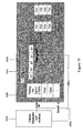
- Figure 3 illustrates a shading of elements according to their organization by nominal source (or collective development as a sub-system) including the tester operating system , user components 292 (e.g., supplied by a user for test purposes), system components 294 (e.g., supplied as software infrastructure for basic connectivity and communication), module development components 296 (e.g., supplied by a module developer), and external components 298 (e.g., supplied by external sources other than module developers).
- nominal source or collective development as a sub-system
- user components 292 e.g., supplied by a user for test purposes
- system components 294 e.g., supplied as software infrastructure for basic connectivity and communication
- module development components 296 e.g., supplied by a module developer
- external components 298 e.g., supplied by external sources other than module developers.
- items 1-3 are created by ICF (installation and configuration files) with information from a CMD (configuration management database), and made available at a well-known location, while items 4-8 are user-specified.
- ICF installation and configuration files
- CMD configuration management database
- items 4-8 are user-specified.
- This section provides descriptions for the items 1-6 above; items 7-8 are described in more detail in section E. Specific methods and rules are preferably used to develop each of these components; these methods and rules will be described in this section with examples.
- Each hardware module provides one or more types of hardware resources (resources for short) for use by the test system.
- the tester Resource Definition is preferably used to declare a set of resource names for the available resource types, and a set of parameter names and types associated with each particular resource type. For instance, the resource name dpin is used to refer to digital tester pins. These resources have parameters such as VIL (for the input low voltage), VIH (for the input high voltage), VOL (for the output low voltage), VOH (for the output high voltage), etc.
- a resource definition file will have the extension ".rsc". Shown below is an example resource definition, containing some tester resources:
- a resource parameter such as Voltage or Time
- Vendors supplying special purpose resources that prefer the specification of different parameters should provide their own resource definition files.
- the Tester Configuration is a set of rules that is preferably used to list the Site Controllers in a particular system configuration, and the connection of the Site Controllers to the Switch Matrix input ports.
- a single Site Controller can be connected to a single switch matrix input port.
- the switch matrix connections serve as implicit identifiers for the Site Controllers in the system (other configurations are possible).
- the following is an example of a typical tester configuration:
- the system configuration for a particular test-floor system is part of the system profile, and is made available as the system configuration file Sys.cfg.
- the Site Controller connected to port 1 (“127.0.0.0" in the above example) may enjoy special status, in which it alone configures the Switch Matrix.
- This "special" Site Controller will be referred to as SITE-1.
- the site controller address in this example is an IP address because the site controllers may be connected to the system controller by an internal network. Conversely, the system controller may be connected to an external network to access files, such as pattern data.
- the Module Configuration allows the specification of the physical configuration of the tester, e.g., the physical location and type of each module in a SYSTEM chassis. This is necessitated by the dynamic nature of the tester bus configuration, which allows a mapping of the tester bus address to the physical slot location. This information allows a hardware discovery process that occurs at system boot-up time to validate the SYSTEM configuration.
- Each output port of the Switch Matrix defines a physical slot, which is preferably occupied by a single hardware module. Shown below is an example of a module configuration specified in the file Modules.cfg in accordance with an embodiment of the invention:
- a slot refers to connector through which a hardware module can be connected, such as an output port of the switch matrix.
- Each configuration definition provides information about the module that may be attached to one or more slots.
- the VendorID specified in a configuration definition is a unique ID associated with a vendor.
- the ModuleID refers to a type of module provided by this vendor. There may be several instances of the same ModuleID in a tester configuration.
- the ModuleDriver refers to a vendor supplied DLL to service the module.
- the Resource refers to the units serviced by this module, and provides a name for the resource type; the resource name is obtained from the resource definition file.
- the first configuration block, slots 1 - 12 and 32 - 48 are serviced by a module produced by vendor 1.
- This vendor provides the module, the identifier "1" to refer to this module type, and the module driver library to control the module.
- This module can provide two types of resource units, one designated by the resource name "dpin”, with preferably a total number of 32 resource units (i.e., "channels"), all of which are available, and the other designated by the resource name "analog”, with a total number of 16 resource units, of which only 9 through 16 are available.
- the second and third configuration blocks are specified in a manner similar to the first configuration.
- a configuration block may have one or more slot identifiers. When a block has more than a single slot identifier, then the identified slots are said to be cloned.
- comments are supported; comments start with the '#' character, and extend to the end of the line.
- DUT pin and pin group definitions are encapsulated within resource type blocks, to allow the compiler to correlate pin and pin group definitions with the allowable parameter settings for Levels, etc.
- the Socket specifies the mapping between DUT pin names and physical tester pin (channel) assignments (the physical tester channel numbers are defined in the module configuration file). Note that different Sockets can be used to support different DUT packages and different load board configurations, etc. For a multi-DUT system, the Socket definitions for DUT/channel assignments can support "cloning" of a basic Socket to multiple sites. However, different Sockets (i.e., different physical mappings for the same logical pins) should respect site module partitions. Thus, in addition to providing DUT pin to tester channel assignments, the socket also effectively defines the site partitioning. A Socket file could thus contain definitions for several individual site sockets. Shown below is a sample socket file defining three DUT sites:
- a Pin Mode Option definition would support the configuration of special options or modes for a tester channel. This could, for example, be used to select and configure channel multiplexing. It is preferred that the Pin Mode Option only be used as part of a Test Plan initialization flow, since it might require significant channel configuration.
- the Pin Option syntax supports vendor-defined options. An example is shown below:
- the resource definition file (Resources.rsc), the system configuration file (Sys.cfg) and the module configuration file (Modules.cfg) are preferably made available at a "well-known" location.
- This "well-known" location is the directory specified by the value of the system environment variable Tester_ACTIVE_CONFIGS. For example, if the value of Tester_ACTIVE_CONFIGS is the directory F: ⁇ Tester_SYS ⁇ configs, the system will expect the following files to be present:
- the Installation and Configuration Management system residing on the host computer will preferably set the value of Tester_ACTIVE_CONFIGS. Every time the ICM creates a new version of one of the above files, it will place the new version in the location pointed to by Tester_ACTIVE_CONFIGS. Note that in addition to the above three files, other system configuration files such as the simulation configuration file are also placed in the location pointed to by Tester_ACTIVE_CONFIGS.
- test plan uses test classes (which are different implementations of a test interface denoted Test), which realize the separation of test data and code for particular types of tests.
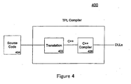
- the plan may be written directly as a C++ test program, or described in a test plan description file, which is processed by a Test Program Generator (translator 402) to produce object-oriented code, such as C++ code.
- the generated C++ code can then be compiled into the executable test program.
- the data required for populating a test class instance, such as levels, timings, etc., are specified by the user in the test plan description file.
- a test program contains a set of user written files that specify details for running a test on a device.
- An embodiment of the invention includes sets of rules that permit a user to write these files using C++ constructs.
- An import of a test description file enables the importing file to refer to names of objects made available by the imported file. This allows the importing file to reference the objects named by the imported file.
- a socket file aaa.soc that imports a pin description file xxx.pin.
- neither of these imports cause the objects described by xxx.pin to come into existence. They merely reference objects that are already assumed to exist.
- test plan mickey.tpl causes the objects in xxx.pin and aaa.soc to be elaborated:
- test program When a test program is compiled, it will elaborate all the objects in the files that are imported by the test plan.
- the set of files imported by a test plan are topologically sorted to yield an order in which the files are elaborated.
- the set of files imported by a test plan is referred to as the import closure of the test plan. If the import closure of a test plan cannot be topologically sorted, then there must be an imports cycle. Such a situation is erroneous, and will be rejected by the compiler.
- Constants are objects whose value is bound at compile time, and cannot be changed. The maximum integer value, for instance, would be a constant.
- the expression bound to variables can change at runtime via an API.
- the types Integer, UnsignedInteger, Double, and String are referred to as Basic Types.
- the Basic Types have no measurement units.
- the Elementary Types which are not basic types are a Double, with an associated measurement unit and a scale.
- the scaling symbols are common engineering scaling symbols:
- constants should not be changed once they are defined.
- the expression bound to a constant can involve previously defined constants and literal values.
- Variables on the other hand, can be changed via an API.
- the expression bound to a variable can involve previously defined variables, constants and literal values.
- Each variable is bound to an expression object which is maintained at runtime. This provides the capability of changing the expression associated with a variable at runtime, and then.re-evaluating all the variables.
- the expression object is a parsed form of the right hand side of a variable or constant definition. In one embodiment, no facility is provided for the changing of constants at runtime. Their value is preferably fixed at compile time.
- the compiler preferably checks that units and types match up. Note that since a Voltage times a Current yields a Power, the equations for PLow and PHigh above will compile. However, a statement such as the following will typically not compile:
- the compiler will allow certain automatic type conversions:
- the TestPlan object provides a UserVars class which is a collection that contains names and their associated expressions, values, and types. User variables can go into a Default User Variables Collection , or into a Named User Variables Collection .
- the name If the name is not qualified, and there is a constant or variable of the same name in the present collection, then the name resolves to that constant or variable.
- Evaluation of a block of definitions in a UserVars collection can be thought of happening sequentially, from the first definition to the last. This may require each variable being defined before it is used.
- a UserVars collection uses a variable from another collection, it preferably uses just the raw value of the variable. No dependency information is maintained between collections. Thus, dependency based re-evaluation can be limited to a single collection.
- the type Expression is a type that is a parsed form of the text corresponding to the right hand side of an assignment.
- the set of user variables in limits.usrv (cf. page) is implemented by the set of calls shown below:
- User-Vars Targeted Re-evaluation is re-evaluation limited to a change to the expression bound to a single name. This would enable the user to change the expression of a single name, and cause the re-evaluation of the collection to take place, taking into consideration only this particular change.
- the setExpression() call can fail if the expression results in a circular dependency. For instance if the following two calls were made, the second call would fail with a circular dependency failure
- a specification set can be thought of as a matrix of expressions, whose columns are the Selectors, whose rows are the variables and whose entries are expressions.
- a particular selector (column) binds each variable (row) to a specific expression (entry). If the list has a single expression, it represents a row with the expression replicated as many times as there are selectors.
- Specification sets can appear in two separate contexts. They could be separately declared in a .spec file, in which case they appear as shown above. These are named specification sets . Otherwise, local specification sets can be declared within a Test Condition Group . In such a declaration, the specification set will not be provided with a name. It will be a local specification set, of significance only to the enclosing test condition group.
- Named specification sets can be modeled after the named user variables collection .
- the above specification set can be modeled as a UserVars collection named Aaa, which will have expressions for xxx[Minnie], xxx[Mickey], xxx[Goofy], xxx[Daisy], yyy[Minnie], and so on.
- Aaa UserVars collection
- a particular selector say Mickey
- the values of xxx, yyy and zzz are obtained from the variable name and the specification set name.
- a test condition group can have at most one specification set, which is either a local specification set, or a reference to a named specification set. Local specification sets appear only in the context of a test condition group, and have no explicitly specified name. Such a specification set has an implicit name that is defined by the name of the enclosing test condition group. To resolve a name in a test condition group at a point where several specification sets and several UserVars collections are visible, the following rules are applied:
- Specification sets can be implemented by the C++ SpecificationSet class.
- the SpecificationSet class has essentially the same API as the UserVars class, except for an extra String parameter for the selector. Consequently, this API is not described in detail.
- All named specification sets are preferably associated with a C++ object of that name.
- a local specification set in the context of a test condition group will have a name that is unique to that test condition group. It is illegal to refer to a variable of a local specification set outside the context of the test condition group that it is defined in.
- the Levels are used to specify parameters of pins and pin groups. It is a collection of declarations of the form:
- each Levels block is preferably made up of a number of levels items , each of which specifies parameters for a pin or pin group.
- Each levels item can specify a number of resource parameters .
- the runtime semantics for the setting of these levels values is as follows:
- the levels items of the Levels block are processed in declaration order. Any pin that occurs in more than one levels item will get processed multiple numbers of times. Multiple specification of values for a single parameter should be maintained and applied in specification order.
- the resource parameters in a levels item are processed in the order they are specified.
- the Delay statements divide up the Levels specification into a number of subsequences, each of which will require separate Test Condition Memory settings for processing.
- the MinDelay statements cause the process of setting levels to pause for at least the specified duration prior to setting the next group of levels.
- Each pin or pin-group name is specified in exactly one resource in a pin description file (suffix .pin), and therefore has a certain set of viable resource parameters specified in the resource file (suffix .rsc). All the parameters named must be from among this set of viable resource parameters, and must be of the same elementary type as the expression used to set their value. Information about the names and types of resource parameters comes from the resource file.
- the resource file Resources.rsc is implicitly imported, providing tester with the names and types for parameters of standard resources such as dpin, and dps.
- Resource parameters are assigned expressions that can use UserVars, and values from named specification sets or a currently visible local specification set.
- Dps pin resources have special parameters PRE_WAIT and POST_WAIT.
- the PRE_WAIT parameter specifies the time that needs to elapse from the time the power pin has reached its destination voltage to the time pattern generation can start.
- the POST_WAIT parameter specifies the time that needs to elapse from the time pattern generation has stopped to the time the power pin shuts off.
- Dps pins also specify how the voltage parameter reaches its final value. They could specify it simply by an equation, as all other pin parameters. In that case the value will be reached as the hardware allows it. They could also specify it using a Slew statement.
- a Slew statement specifies that the power supply voltage reaches its final value from the initial value in a ramp with a specified absolute Voltage Slew Rate.
- the test condition group TCG1 describes a specification set with three selectors named "min”, "typ” and "max”. There can be any number of distinct selectors.
- variables v_il, v_ih, t_le and t_te are initialized with triples of values, corresponding to the selectors. So in the above example, an instance of TCG1 with the selector "min” will bind the variable v_il with the first numeric value, (vInputLow+0.0). It bears repetition that the selectors for a specification set are user defined, and any number of them is allowed. The only requirement is that:
- the selectors of a specification set be unique identifiers.
- Each value specified in the specification set is associated with an array of values that exactly the same number of elements as the set of selectors. Picking the i th selector will cause each value to be bound to the i th value of its associated vector of values.
- Timings there should not be more than one Timings and more than one Levels in a TCG. Thus, in summary, there should be at least one of Timings or Levels, and at most one of each.
- This sequencing order enables the test writer to control the explicit power sequencing of power supplies. Furthermore, if a levels item occurs twice, naming the same pin-parameters for a pin, then that pin-parameter gets set twice. This can happen programmatically also.
- Each bin in a BinGroup has:
- Bin names are local to a BinGroup.
- TestPlan state will be include number of BinGroup members, one for each BinGroup declaration.
- the C++ for the above BinDefinitions would be as follows:
- the TestPlan preferably contains a member variable, m_modifiedCounters, which is the set of counters modified by running the test on a DUT. This set is initialized to the empty set at the start of the test. At each place an IncrementCounters call is made, code will be generated to add the named counters to the m_modifiedCounters member. Thus, this member gathers together all the counters that were modified during the execution of a test on a DUT.
- m_modifiedCounters is the set of counters modified by running the test on a DUT. This set is initialized to the empty set at the start of the test. At each place an IncrementCounters call is made, code will be generated to add the named counters to the m_modifiedCounters member. Thus, this member gathers together all the counters that were modified during the execution of a test on a DUT.
- a TPL provides a generic mechanism for defining a test class in the test system. Test engineers can use this mechanism to create custom test classes that can be loaded and used by the test system without additional facilities. Test engineers can also develop their own test classes implementing the ITest and IFlowable interfaces described above. A pre-header supports the feature of custom test classes by providing introspection capabilities to the C++ language.
- test program compiler 400 The process of conversion from a test plan description to an implementation of ITestPlan is accomplished by the test program compiler 400. This process occurs in two phases: translation and compilation.
- the Site Controller software loads the Test Program DLL into its process space and calls a "factory" function within the DLL to create an instance of the Test Plan object. Once the Test Plan object has been created, the Site Controller software can then execute the test plan or interact with it in any other way necessary.
- the user can override these default values, e.g., through tester environment variables or setup options.
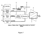
- a single test site in the test system can be associated with multiple top-level pattern lists. However, there is only a single execution context for test plans at any given time. Since a top-level pattern list defines an execution sequence for the patterns referred to (hierarchically) by it, the active execution context is the one corresponding to the currently selected top-level pattern list. Note that this does not imply that only the patterns contained in a single pattern list can be loaded on the hardware at one time; rather, the set of patterns that are required to be loaded on the hardware to make an execution sequence viable must always be a subset of all the currently loaded patterns.
- the execution sequence is as below. As earlier, the
Landscapes
- Engineering & Computer Science (AREA)
- General Engineering & Computer Science (AREA)
- Physics & Mathematics (AREA)
- General Physics & Mathematics (AREA)
- Theoretical Computer Science (AREA)
- Computer Hardware Design (AREA)
- Quality & Reliability (AREA)
- Software Systems (AREA)
- Tests Of Electronic Circuits (AREA)
- Test And Diagnosis Of Digital Computers (AREA)
Applications Claiming Priority (3)
| Application Number | Priority Date | Filing Date | Title |
|---|---|---|---|
| US57357704P | 2004-05-22 | 2004-05-22 | |
| US10/918,714 US7197417B2 (en) | 2003-02-14 | 2004-08-13 | Method and structure to develop a test program for semiconductor integrated circuits |
| PCT/JP2005/009813 WO2005114235A2 (en) | 2004-05-22 | 2005-05-23 | Method and structure to develop a test program for semiconductor integrated circuits |
Publications (2)
| Publication Number | Publication Date |
|---|---|
| EP1756601A2 EP1756601A2 (en) | 2007-02-28 |
| EP1756601B1 true EP1756601B1 (en) | 2009-12-09 |
Family
ID=34975206
Family Applications (1)
| Application Number | Title | Priority Date | Filing Date |
|---|---|---|---|
| EP05743229A Expired - Lifetime EP1756601B1 (en) | 2004-05-22 | 2005-05-23 | Method and structure to develop a test program for semiconductor integrated circuits |
Country Status (6)
| Country | Link |
|---|---|
| US (1) | US7197417B2 (enExample) |
| EP (1) | EP1756601B1 (enExample) |
| JP (1) | JP4516961B2 (enExample) |
| KR (1) | KR20070014206A (enExample) |
| TW (1) | TWI365387B (enExample) |
| WO (1) | WO2005114235A2 (enExample) |
Cited By (1)
| Publication number | Priority date | Publication date | Assignee | Title |
|---|---|---|---|---|
| JP2007528993A (ja) * | 2004-05-22 | 2007-10-18 | 株式会社アドバンテスト | 半導体集積回路のための試験プログラムを開発するための方法及び構造 |
Families Citing this family (62)
| Publication number | Priority date | Publication date | Assignee | Title |
|---|---|---|---|---|
| US7184917B2 (en) | 2003-02-14 | 2007-02-27 | Advantest America R&D Center, Inc. | Method and system for controlling interchangeable components in a modular test system |
| US7437261B2 (en) * | 2003-02-14 | 2008-10-14 | Advantest Corporation | Method and apparatus for testing integrated circuits |
| US7340364B1 (en) * | 2003-02-26 | 2008-03-04 | Advantest Corporation | Test apparatus, and control method |
| CN1567223A (zh) * | 2003-07-09 | 2005-01-19 | 松下电器产业株式会社 | 程序生成装置、方法及程序 |
| US7197416B2 (en) * | 2004-05-22 | 2007-03-27 | Advantest America R&D Center, Inc. | Supporting calibration and diagnostics in an open architecture test system |
| US7430486B2 (en) * | 2004-05-22 | 2008-09-30 | Advantest America R&D Center, Inc. | Datalog support in a modular test system |
| US7210087B2 (en) * | 2004-05-22 | 2007-04-24 | Advantest America R&D Center, Inc. | Method and system for simulating a modular test system |
| KR100548199B1 (ko) * | 2004-07-15 | 2006-02-02 | 삼성전자주식회사 | 아날로그/디지털 혼합 신호 반도체 디바이스 테스트 장치 |
| US8725748B1 (en) * | 2004-08-27 | 2014-05-13 | Advanced Micro Devices, Inc. | Method and system for storing and retrieving semiconductor tester information |
| US7865880B2 (en) * | 2004-11-16 | 2011-01-04 | Lsi Corporation | System and/or method for implementing efficient techniques for testing common information model providers |
| DE102006001776A1 (de) * | 2005-01-12 | 2006-11-09 | Advanced Testing Technologies, Inc. | Testprogrammsatz Minimierung der Veralterung durch Software- und automatische Testgeräteprozesse |
| US8484618B2 (en) | 2005-01-12 | 2013-07-09 | Advanced Testing Technologies, Inc. | Test program set obsolescence mitigation through software and automatic test equipment processes |
| US8214800B2 (en) * | 2005-03-02 | 2012-07-03 | Advantest Corporation | Compact representation of vendor hardware module revisions in an open architecture test system |
| US7487422B2 (en) * | 2005-04-29 | 2009-02-03 | Teradyne, Inc. | Delayed processing of site-aware objects |
| US7253607B2 (en) * | 2005-04-29 | 2007-08-07 | Teradyne, Inc. | Site-aware objects |
| US7254508B2 (en) * | 2005-04-29 | 2007-08-07 | Teradyne, Inc. | Site loops |
| JP4427002B2 (ja) * | 2005-05-20 | 2010-03-03 | 株式会社アドバンテスト | 半導体試験用プログラムデバッグ装置 |
| US7528622B2 (en) * | 2005-07-06 | 2009-05-05 | Optimal Test Ltd. | Methods for slow test time detection of an integrated circuit during parallel testing |
| US7458043B1 (en) * | 2005-09-15 | 2008-11-25 | Unisys Corporation | Generation of tests used in simulating an electronic circuit design |
| US7567947B2 (en) * | 2006-04-04 | 2009-07-28 | Optimaltest Ltd. | Methods and systems for semiconductor testing using a testing scenario language |
| US10838714B2 (en) * | 2006-04-24 | 2020-11-17 | Servicenow, Inc. | Applying packages to configure software stacks |
| US7590903B2 (en) * | 2006-05-15 | 2009-09-15 | Verigy (Singapore) Pte. Ltd. | Re-configurable architecture for automated test equipment |
| US7532024B2 (en) * | 2006-07-05 | 2009-05-12 | Optimaltest Ltd. | Methods and systems for semiconductor testing using reference dice |
| US7558770B2 (en) * | 2006-08-23 | 2009-07-07 | International Business Machines Corporation | Method and system to detect application non-conformance |
| US8359585B1 (en) | 2007-01-18 | 2013-01-22 | Advanced Testing Technologies, Inc. | Instrumentation ATS/TPS mitigation utilizing I/O data stream |
| US7761471B1 (en) * | 2007-10-16 | 2010-07-20 | Jpmorgan Chase Bank, N.A. | Document management techniques to account for user-specific patterns in document metadata |
| US7809520B2 (en) * | 2007-11-05 | 2010-10-05 | Advantest Corporation | Test equipment, method for loading test plan and program product |
| US20090319997A1 (en) * | 2008-06-20 | 2009-12-24 | Microsoft Corporation | Precondition rules for static verification of code |
| WO2010055964A1 (en) * | 2008-11-17 | 2010-05-20 | Industry-University Cooperation Foundation Hanyang University | Method of testing semiconductor device |
| US8149721B2 (en) * | 2008-12-08 | 2012-04-03 | Advantest Corporation | Test apparatus and test method |
| US20110012902A1 (en) * | 2009-07-16 | 2011-01-20 | Jaganathan Rajagopalan | Method and system for visualizing the performance of applications |
| KR101028359B1 (ko) * | 2009-12-10 | 2011-04-11 | 주식회사 이노와이어리스 | 스크립트를 이용한 dut 자동화 테스트 장치 |
| US10089119B2 (en) | 2009-12-18 | 2018-10-02 | Microsoft Technology Licensing, Llc | API namespace virtualization |
| CN103038656B (zh) * | 2010-05-05 | 2015-01-14 | 泰拉丁公司 | 用于半导体装置的并行测试的系统 |
| US8776014B2 (en) * | 2010-09-23 | 2014-07-08 | Microsoft Corporation | Software build analysis |
| JP5626786B2 (ja) * | 2010-11-09 | 2014-11-19 | インターナショナル・ビジネス・マシーンズ・コーポレーションInternational Business Machines Corporation | ソフトウエア開発支援方法とソフトウエア開発支援装置とソフトウエア開発支援プログラム |
| TW201301135A (zh) * | 2011-06-16 | 2013-01-01 | Hon Hai Prec Ind Co Ltd | 零件資料轉檔系統及方法 |
| US8776094B2 (en) | 2011-08-11 | 2014-07-08 | Microsoft Corporation | Runtime system |
| EP2557501B1 (en) * | 2011-08-11 | 2016-03-16 | Intel Deutschland GmbH | Circuit arrangement and method for testing same |
| US8695021B2 (en) | 2011-08-31 | 2014-04-08 | Microsoft Corporation | Projecting native application programming interfaces of an operating system into other programming languages |
| US9217772B2 (en) * | 2012-07-31 | 2015-12-22 | Infineon Technologies Ag | Systems and methods for characterizing devices |
| US8789006B2 (en) * | 2012-11-01 | 2014-07-22 | Nvidia Corporation | System, method, and computer program product for testing an integrated circuit from a command line |
| CN103092156B (zh) * | 2012-12-26 | 2016-02-10 | 莱诺斯科技(北京)有限公司 | 设备可替换型自动化测试系统及方法 |
| US9785542B2 (en) * | 2013-04-16 | 2017-10-10 | Advantest Corporation | Implementing edit and update functionality within a development environment used to compile test plans for automated semiconductor device testing |
| US9785526B2 (en) * | 2013-04-30 | 2017-10-10 | Advantest Corporation | Automated generation of a test class pre-header from an interactive graphical user interface |
| US10635504B2 (en) | 2014-10-16 | 2020-04-28 | Microsoft Technology Licensing, Llc | API versioning independent of product releases |
| EP3213214B1 (fr) * | 2014-10-30 | 2021-03-03 | SPHEREA Test & Services | Banc et logiciel pour tester un appareillage electrique, notamment un calculateur |
| EP3032270A1 (en) * | 2014-12-12 | 2016-06-15 | Airbus Defence and Space, S.A. | Method and system for performing electrical tests to complex devices |
| KR101688632B1 (ko) * | 2015-07-31 | 2016-12-22 | 한국전자통신연구원 | 라이브러리 적재 탐지를 위한 방법 및 장치 |
| US10095596B1 (en) * | 2015-12-18 | 2018-10-09 | Amazon Technologies, Inc. | Executing integration tests in a distributed load and performance evaluation framework |
| US9733930B2 (en) * | 2015-12-21 | 2017-08-15 | Successfactors, Inc. | Logical level difference detection between software revisions |
| US10191736B2 (en) * | 2017-04-28 | 2019-01-29 | Servicenow, Inc. | Systems and methods for tracking configuration file changes |
| TWI676906B (zh) * | 2018-04-13 | 2019-11-11 | 和碩聯合科技股份有限公司 | 提示方法及其電腦系統 |
| KR102583174B1 (ko) | 2018-06-12 | 2023-09-26 | 삼성전자주식회사 | 테스트 인터페이스 보드, 이를 포함하는 테스트 시스템 및 이의 동작 방법 |
| US11159303B1 (en) | 2018-11-20 | 2021-10-26 | Mitsubishi Electric Corporation | Communication system, list distribution station, communication method, and computer readable medium |
| JP7122236B2 (ja) * | 2018-11-28 | 2022-08-19 | 東京エレクトロン株式会社 | 検査装置、メンテナンス方法、及びプログラム |
| US11182265B2 (en) * | 2019-01-09 | 2021-11-23 | International Business Machines Corporation | Method and apparatus for test generation |
| CN110082666B (zh) * | 2019-04-10 | 2022-02-22 | 杭州微纳核芯电子科技有限公司 | 芯片测试分析方法、装置、设备及存储介质 |
| US11656270B2 (en) * | 2019-05-09 | 2023-05-23 | Ase Test, Inc. | Apparatus and method of testing electronic components |
| CN111880079B (zh) * | 2020-07-24 | 2022-12-13 | 安测半导体技术(江苏)有限公司 | 一种芯片测试监控方法及服务器 |
| CN112100954B (zh) * | 2020-08-31 | 2024-07-09 | 北京百度网讯科技有限公司 | 验证芯片的方法、装置和计算机存储介质 |
| CN113051114A (zh) * | 2021-03-19 | 2021-06-29 | 无锡市软测认证有限公司 | 一种用于提高芯片测试效率的方法 |
Family Cites Families (17)
| Publication number | Priority date | Publication date | Assignee | Title |
|---|---|---|---|---|
| DK557884A (da) * | 1983-11-25 | 1985-05-26 | Mars Inc | Automatisk testudstyr |
| US5488573A (en) | 1993-09-02 | 1996-01-30 | Matsushita Electric Industrial Co., Ltd. | Method for generating test programs |
| US5892949A (en) | 1996-08-30 | 1999-04-06 | Schlumberger Technologies, Inc. | ATE test programming architecture |
| US6182258B1 (en) | 1997-06-03 | 2001-01-30 | Verisity Ltd. | Method and apparatus for test generation during circuit design |
| US6028439A (en) | 1997-10-31 | 2000-02-22 | Credence Systems Corporation | Modular integrated circuit tester with distributed synchronization and control |
| US6195774B1 (en) | 1998-08-13 | 2001-02-27 | Xilinx, Inc. | Boundary-scan method using object-oriented programming language |
| US6601018B1 (en) | 1999-02-04 | 2003-07-29 | International Business Machines Corporation | Automatic test framework system and method in software component testing |
| US6427223B1 (en) | 1999-04-30 | 2002-07-30 | Synopsys, Inc. | Method and apparatus for adaptive verification of circuit designs |
| US6678643B1 (en) * | 1999-06-28 | 2004-01-13 | Advantest Corp. | Event based semiconductor test system |
| US6405364B1 (en) | 1999-08-31 | 2002-06-11 | Accenture Llp | Building techniques in a development architecture framework |
| US6779140B2 (en) | 2001-06-29 | 2004-08-17 | Agilent Technologies, Inc. | Algorithmically programmable memory tester with test sites operating in a slave mode |
| JP2003173266A (ja) * | 2001-12-05 | 2003-06-20 | Mitsubishi Electric Corp | プログラム生成システム、プログラム変換システム、プログラム変換方法、半導体装置開発システム、記録媒体及びプログラム |
| JP4508657B2 (ja) * | 2002-04-11 | 2010-07-21 | 株式会社アドバンテスト | Asic/soc製造におけるプロトタイプホールドを回避するための製造方法と装置 |
| US7437261B2 (en) | 2003-02-14 | 2008-10-14 | Advantest Corporation | Method and apparatus for testing integrated circuits |
| US7197417B2 (en) * | 2003-02-14 | 2007-03-27 | Advantest America R&D Center, Inc. | Method and structure to develop a test program for semiconductor integrated circuits |
| US7184917B2 (en) | 2003-02-14 | 2007-02-27 | Advantest America R&D Center, Inc. | Method and system for controlling interchangeable components in a modular test system |
| TWI344595B (en) | 2003-02-14 | 2011-07-01 | Advantest Corp | Method and structure to develop a test program for semiconductor integrated circuits |
-
2004
- 2004-08-13 US US10/918,714 patent/US7197417B2/en not_active Expired - Lifetime
-
2005
- 2005-05-18 TW TW094116145A patent/TWI365387B/zh not_active IP Right Cessation
- 2005-05-23 JP JP2006519571A patent/JP4516961B2/ja not_active Expired - Fee Related
- 2005-05-23 KR KR1020067027010A patent/KR20070014206A/ko not_active Withdrawn
- 2005-05-23 EP EP05743229A patent/EP1756601B1/en not_active Expired - Lifetime
- 2005-05-23 WO PCT/JP2005/009813 patent/WO2005114235A2/en not_active Ceased
Cited By (1)
| Publication number | Priority date | Publication date | Assignee | Title |
|---|---|---|---|---|
| JP2007528993A (ja) * | 2004-05-22 | 2007-10-18 | 株式会社アドバンテスト | 半導体集積回路のための試験プログラムを開発するための方法及び構造 |
Also Published As
| Publication number | Publication date |
|---|---|
| US7197417B2 (en) | 2007-03-27 |
| JP2007528993A (ja) | 2007-10-18 |
| TW200617704A (en) | 2006-06-01 |
| TWI365387B (en) | 2012-06-01 |
| WO2005114235A2 (en) | 2005-12-01 |
| WO2005114235A3 (en) | 2006-04-20 |
| JP4516961B2 (ja) | 2010-08-04 |
| EP1756601A2 (en) | 2007-02-28 |
| US20050154551A1 (en) | 2005-07-14 |
| KR20070014206A (ko) | 2007-01-31 |
Similar Documents
| Publication | Publication Date | Title |
|---|---|---|
| EP1756601B1 (en) | Method and structure to develop a test program for semiconductor integrated circuits | |
| EP1756602B1 (en) | Method and structure to develop a test program for semiconductor integrated circuits | |
| EP1592976B1 (en) | Method and structure to develop a test program for semiconductor integrated circuits | |
| EP1756603B1 (en) | Method and system for controlling interchangeable components in a modular test system | |
| US8255198B2 (en) | Method and structure to develop a test program for semiconductor integrated circuits | |
| CN100541218C (zh) | 开发用于半导体集成电路的测试程序的方法和结构 | |
| JP2007528993A5 (enExample) | ||
| KR20070023762A (ko) | 반도체 집적 회로를 위한 테스트 프로그램을 개발하는 방법및 구조 | |
| KR20070035507A (ko) | 모듈식 테스트 시스템에서 호환성있는 컴포넌트를 제어하는방법 및 시스템 | |
| Rajsuman et al. | Open architecture test system: System architecture and design |
Legal Events
| Date | Code | Title | Description |
|---|---|---|---|
| PUAI | Public reference made under article 153(3) epc to a published international application that has entered the european phase |
Free format text: ORIGINAL CODE: 0009012 |
|
| 17P | Request for examination filed |
Effective date: 20061116 |
|
| AK | Designated contracting states |
Kind code of ref document: A2 Designated state(s): AT BE BG CH CY CZ DE DK EE ES FI FR GB GR HU IE IS IT LI LT LU MC NL PL PT RO SE SI SK TR |
|
| 17Q | First examination report despatched |
Effective date: 20070413 |
|
| DAX | Request for extension of the european patent (deleted) | ||
| GRAP | Despatch of communication of intention to grant a patent |
Free format text: ORIGINAL CODE: EPIDOSNIGR1 |
|
| GRAS | Grant fee paid |
Free format text: ORIGINAL CODE: EPIDOSNIGR3 |
|
| GRAA | (expected) grant |
Free format text: ORIGINAL CODE: 0009210 |
|
| AK | Designated contracting states |
Kind code of ref document: B1 Designated state(s): AT BE BG CH CY CZ DE DK EE ES FI FR GB GR HU IE IS IT LI LT LU MC NL PL PT RO SE SI SK TR |
|
| REG | Reference to a national code |
Ref country code: GB Ref legal event code: FG4D |
|
| REG | Reference to a national code |
Ref country code: CH Ref legal event code: EP |
|
| REG | Reference to a national code |
Ref country code: IE Ref legal event code: FG4D |
|
| REF | Corresponds to: |
Ref document number: 602005018204 Country of ref document: DE Date of ref document: 20100121 Kind code of ref document: P |
|
| REG | Reference to a national code |
Ref country code: NL Ref legal event code: VDEP Effective date: 20091209 |
|
| PG25 | Lapsed in a contracting state [announced via postgrant information from national office to epo] |
Ref country code: SE Free format text: LAPSE BECAUSE OF FAILURE TO SUBMIT A TRANSLATION OF THE DESCRIPTION OR TO PAY THE FEE WITHIN THE PRESCRIBED TIME-LIMIT Effective date: 20091209 Ref country code: FI Free format text: LAPSE BECAUSE OF FAILURE TO SUBMIT A TRANSLATION OF THE DESCRIPTION OR TO PAY THE FEE WITHIN THE PRESCRIBED TIME-LIMIT Effective date: 20091209 Ref country code: LT Free format text: LAPSE BECAUSE OF FAILURE TO SUBMIT A TRANSLATION OF THE DESCRIPTION OR TO PAY THE FEE WITHIN THE PRESCRIBED TIME-LIMIT Effective date: 20091209 |
|
| LTIE | Lt: invalidation of european patent or patent extension |
Effective date: 20091209 |
|
| PG25 | Lapsed in a contracting state [announced via postgrant information from national office to epo] |
Ref country code: SI Free format text: LAPSE BECAUSE OF FAILURE TO SUBMIT A TRANSLATION OF THE DESCRIPTION OR TO PAY THE FEE WITHIN THE PRESCRIBED TIME-LIMIT Effective date: 20091209 Ref country code: PL Free format text: LAPSE BECAUSE OF FAILURE TO SUBMIT A TRANSLATION OF THE DESCRIPTION OR TO PAY THE FEE WITHIN THE PRESCRIBED TIME-LIMIT Effective date: 20091209 |
|
| PG25 | Lapsed in a contracting state [announced via postgrant information from national office to epo] |
Ref country code: AT Free format text: LAPSE BECAUSE OF FAILURE TO SUBMIT A TRANSLATION OF THE DESCRIPTION OR TO PAY THE FEE WITHIN THE PRESCRIBED TIME-LIMIT Effective date: 20091209 |
|
| PG25 | Lapsed in a contracting state [announced via postgrant information from national office to epo] |
Ref country code: RO Free format text: LAPSE BECAUSE OF FAILURE TO SUBMIT A TRANSLATION OF THE DESCRIPTION OR TO PAY THE FEE WITHIN THE PRESCRIBED TIME-LIMIT Effective date: 20091209 Ref country code: PT Free format text: LAPSE BECAUSE OF FAILURE TO SUBMIT A TRANSLATION OF THE DESCRIPTION OR TO PAY THE FEE WITHIN THE PRESCRIBED TIME-LIMIT Effective date: 20100409 Ref country code: NL Free format text: LAPSE BECAUSE OF FAILURE TO SUBMIT A TRANSLATION OF THE DESCRIPTION OR TO PAY THE FEE WITHIN THE PRESCRIBED TIME-LIMIT Effective date: 20091209 Ref country code: ES Free format text: LAPSE BECAUSE OF FAILURE TO SUBMIT A TRANSLATION OF THE DESCRIPTION OR TO PAY THE FEE WITHIN THE PRESCRIBED TIME-LIMIT Effective date: 20100320 Ref country code: IS Free format text: LAPSE BECAUSE OF FAILURE TO SUBMIT A TRANSLATION OF THE DESCRIPTION OR TO PAY THE FEE WITHIN THE PRESCRIBED TIME-LIMIT Effective date: 20100409 Ref country code: BG Free format text: LAPSE BECAUSE OF FAILURE TO SUBMIT A TRANSLATION OF THE DESCRIPTION OR TO PAY THE FEE WITHIN THE PRESCRIBED TIME-LIMIT Effective date: 20100309 Ref country code: EE Free format text: LAPSE BECAUSE OF FAILURE TO SUBMIT A TRANSLATION OF THE DESCRIPTION OR TO PAY THE FEE WITHIN THE PRESCRIBED TIME-LIMIT Effective date: 20091209 |
|
| PG25 | Lapsed in a contracting state [announced via postgrant information from national office to epo] |
Ref country code: SK Free format text: LAPSE BECAUSE OF FAILURE TO SUBMIT A TRANSLATION OF THE DESCRIPTION OR TO PAY THE FEE WITHIN THE PRESCRIBED TIME-LIMIT Effective date: 20091209 Ref country code: BE Free format text: LAPSE BECAUSE OF FAILURE TO SUBMIT A TRANSLATION OF THE DESCRIPTION OR TO PAY THE FEE WITHIN THE PRESCRIBED TIME-LIMIT Effective date: 20091209 Ref country code: CZ Free format text: LAPSE BECAUSE OF FAILURE TO SUBMIT A TRANSLATION OF THE DESCRIPTION OR TO PAY THE FEE WITHIN THE PRESCRIBED TIME-LIMIT Effective date: 20091209 |
|
| PGFP | Annual fee paid to national office [announced via postgrant information from national office to epo] |
Ref country code: DE Payment date: 20100519 Year of fee payment: 6 |
|
| PLBE | No opposition filed within time limit |
Free format text: ORIGINAL CODE: 0009261 |
|
| STAA | Information on the status of an ep patent application or granted ep patent |
Free format text: STATUS: NO OPPOSITION FILED WITHIN TIME LIMIT |
|
| PG25 | Lapsed in a contracting state [announced via postgrant information from national office to epo] |
Ref country code: GR Free format text: LAPSE BECAUSE OF FAILURE TO SUBMIT A TRANSLATION OF THE DESCRIPTION OR TO PAY THE FEE WITHIN THE PRESCRIBED TIME-LIMIT Effective date: 20100310 Ref country code: CY Free format text: LAPSE BECAUSE OF FAILURE TO SUBMIT A TRANSLATION OF THE DESCRIPTION OR TO PAY THE FEE WITHIN THE PRESCRIBED TIME-LIMIT Effective date: 20091209 |
|
| 26N | No opposition filed |
Effective date: 20100910 |
|
| PG25 | Lapsed in a contracting state [announced via postgrant information from national office to epo] |
Ref country code: MC Free format text: LAPSE BECAUSE OF NON-PAYMENT OF DUE FEES Effective date: 20100531 |
|
| REG | Reference to a national code |
Ref country code: CH Ref legal event code: PL |
|
| GBPC | Gb: european patent ceased through non-payment of renewal fee |
Effective date: 20100523 |
|
| PG25 | Lapsed in a contracting state [announced via postgrant information from national office to epo] |
Ref country code: DK Free format text: LAPSE BECAUSE OF FAILURE TO SUBMIT A TRANSLATION OF THE DESCRIPTION OR TO PAY THE FEE WITHIN THE PRESCRIBED TIME-LIMIT Effective date: 20091209 |
|
| REG | Reference to a national code |
Ref country code: FR Ref legal event code: ST Effective date: 20110131 |
|
| PG25 | Lapsed in a contracting state [announced via postgrant information from national office to epo] |
Ref country code: CH Free format text: LAPSE BECAUSE OF NON-PAYMENT OF DUE FEES Effective date: 20100531 Ref country code: LI Free format text: LAPSE BECAUSE OF NON-PAYMENT OF DUE FEES Effective date: 20100531 |
|
| PG25 | Lapsed in a contracting state [announced via postgrant information from national office to epo] |
Ref country code: IT Free format text: LAPSE BECAUSE OF FAILURE TO SUBMIT A TRANSLATION OF THE DESCRIPTION OR TO PAY THE FEE WITHIN THE PRESCRIBED TIME-LIMIT Effective date: 20091209 |
|
| PG25 | Lapsed in a contracting state [announced via postgrant information from national office to epo] |
Ref country code: IE Free format text: LAPSE BECAUSE OF NON-PAYMENT OF DUE FEES Effective date: 20100523 |
|
| PG25 | Lapsed in a contracting state [announced via postgrant information from national office to epo] |
Ref country code: FR Free format text: LAPSE BECAUSE OF NON-PAYMENT OF DUE FEES Effective date: 20100531 |
|
| PG25 | Lapsed in a contracting state [announced via postgrant information from national office to epo] |
Ref country code: GB Free format text: LAPSE BECAUSE OF NON-PAYMENT OF DUE FEES Effective date: 20100523 |
|
| REG | Reference to a national code |
Ref country code: DE Ref legal event code: R119 Ref document number: 602005018204 Country of ref document: DE Effective date: 20111201 |
|
| PG25 | Lapsed in a contracting state [announced via postgrant information from national office to epo] |
Ref country code: LU Free format text: LAPSE BECAUSE OF NON-PAYMENT OF DUE FEES Effective date: 20100523 Ref country code: HU Free format text: LAPSE BECAUSE OF FAILURE TO SUBMIT A TRANSLATION OF THE DESCRIPTION OR TO PAY THE FEE WITHIN THE PRESCRIBED TIME-LIMIT Effective date: 20100610 |
|
| PG25 | Lapsed in a contracting state [announced via postgrant information from national office to epo] |
Ref country code: TR Free format text: LAPSE BECAUSE OF FAILURE TO SUBMIT A TRANSLATION OF THE DESCRIPTION OR TO PAY THE FEE WITHIN THE PRESCRIBED TIME-LIMIT Effective date: 20091209 |
|
| PG25 | Lapsed in a contracting state [announced via postgrant information from national office to epo] |
Ref country code: DE Free format text: LAPSE BECAUSE OF NON-PAYMENT OF DUE FEES Effective date: 20111201 |