EP1754944A2 - Verfahren und Vorrichtung zur gerichteten und kontrollierten Kühlung in Vakuumöfen - Google Patents
Verfahren und Vorrichtung zur gerichteten und kontrollierten Kühlung in Vakuumöfen Download PDFInfo
- Publication number
- EP1754944A2 EP1754944A2 EP06110788A EP06110788A EP1754944A2 EP 1754944 A2 EP1754944 A2 EP 1754944A2 EP 06110788 A EP06110788 A EP 06110788A EP 06110788 A EP06110788 A EP 06110788A EP 1754944 A2 EP1754944 A2 EP 1754944A2
- Authority
- EP
- European Patent Office
- Prior art keywords
- gas
- plenum
- cooling
- vacuum furnace
- hot zone
- Prior art date
- Legal status (The legal status is an assumption and is not a legal conclusion. Google has not performed a legal analysis and makes no representation as to the accuracy of the status listed.)
- Granted
Links
- 238000001816 cooling Methods 0.000 title claims description 50
- 238000000034 method Methods 0.000 title claims description 10
- 239000007789 gas Substances 0.000 claims description 164
- 239000000112 cooling gas Substances 0.000 claims description 9
- 238000005086 pumping Methods 0.000 claims 1
- 238000013461 design Methods 0.000 description 7
- 238000013459 approach Methods 0.000 description 4
- 239000011261 inert gas Substances 0.000 description 4
- 238000004519 manufacturing process Methods 0.000 description 3
- 238000010438 heat treatment Methods 0.000 description 2
- 238000003466 welding Methods 0.000 description 2
- 238000005219 brazing Methods 0.000 description 1
- 238000005094 computer simulation Methods 0.000 description 1
- 230000001276 controlling effect Effects 0.000 description 1
- 238000012423 maintenance Methods 0.000 description 1
- 238000012986 modification Methods 0.000 description 1
- 230000004048 modification Effects 0.000 description 1
- 238000012545 processing Methods 0.000 description 1
- 230000001105 regulatory effect Effects 0.000 description 1
- 238000005245 sintering Methods 0.000 description 1
- 230000003245 working effect Effects 0.000 description 1
Images




Classifications
-
- F—MECHANICAL ENGINEERING; LIGHTING; HEATING; WEAPONS; BLASTING
- F27—FURNACES; KILNS; OVENS; RETORTS
- F27D—DETAILS OR ACCESSORIES OF FURNACES, KILNS, OVENS OR RETORTS, IN SO FAR AS THEY ARE OF KINDS OCCURRING IN MORE THAN ONE KIND OF FURNACE
- F27D9/00—Cooling of furnaces or of charges therein
-
- C—CHEMISTRY; METALLURGY
- C21—METALLURGY OF IRON
- C21D—MODIFYING THE PHYSICAL STRUCTURE OF FERROUS METALS; GENERAL DEVICES FOR HEAT TREATMENT OF FERROUS OR NON-FERROUS METALS OR ALLOYS; MAKING METAL MALLEABLE, e.g. BY DECARBURISATION OR TEMPERING
- C21D1/00—General methods or devices for heat treatment, e.g. annealing, hardening, quenching or tempering
- C21D1/56—General methods or devices for heat treatment, e.g. annealing, hardening, quenching or tempering characterised by the quenching agents
- C21D1/613—Gases; Liquefied or solidified normally gaseous material
-
- C—CHEMISTRY; METALLURGY
- C21—METALLURGY OF IRON
- C21D—MODIFYING THE PHYSICAL STRUCTURE OF FERROUS METALS; GENERAL DEVICES FOR HEAT TREATMENT OF FERROUS OR NON-FERROUS METALS OR ALLOYS; MAKING METAL MALLEABLE, e.g. BY DECARBURISATION OR TEMPERING
- C21D1/00—General methods or devices for heat treatment, e.g. annealing, hardening, quenching or tempering
- C21D1/62—Quenching devices
- C21D1/667—Quenching devices for spray quenching
-
- F—MECHANICAL ENGINEERING; LIGHTING; HEATING; WEAPONS; BLASTING
- F27—FURNACES; KILNS; OVENS; RETORTS
- F27B—FURNACES, KILNS, OVENS OR RETORTS IN GENERAL; OPEN SINTERING OR LIKE APPARATUS
- F27B5/00—Muffle furnaces; Retort furnaces; Other furnaces in which the charge is held completely isolated
- F27B5/06—Details, accessories or equipment specially adapted for furnaces of these types
- F27B5/16—Arrangements of air or gas supply devices
Definitions
- Vacuum furnaces for heat treating, brazing, sintering, and other heat processing generally run cycles with heating ramps that are controlled or uncontrolled to some set point temperature. The parts, load, or work are then cooled down. Cooling modes include vacuum or non-circulated inert gas cooling, forced gas cooling via circulation, controlled cooling, or a combination of different cooling steps.
- the first type involves mounting the blower, fan, and motor assembly with heat exchanger internally to the main vacuum vessel. Alternatively, these parts can also be mounted outside of the vacuum chamber via piping connections. Both approaches work; however, the internal type of cooling arrangement tends to require higher and more frequent maintenance due to the proximity of the moving parts to the heated areas.
- This invention relates to controlled and directional cooling to provide optimum metallurgical results while minimizing distortion on the parts being processed within the vacuum furnace.
- This concept has been used for furnaces with internal cooling arrangements, and directional cooling for such an arrangement has been traditionally achieved via moving baffles. These baffles are, however, directly exposed to the heat inside the furnace. As such, they tend to warp and thus fail to open or close to the desired set point resulting in poor performance.
- the present invention uses an external arrangement that removes the dangers involved in using internal parts and thus provides reliable, repeatable, and predictable performance and results.
- the plenum wraps around a significant portion of the hot zone enclosure (e.g., 95%), and the nozzles are positioned in such a manner as to still provide uniform cooling.
- the present invention is directed at an external gas cooling arrangement providing directional cooling from non-circumferential sectors so that different levels of cooling may be applied to the load from different sections of the circumference of the plenum.
- the present invention in one aspect, comprises a cooling vacuum furnace where there is an external gas cooling arrangement and a design that divides the internal chamber of the plenum into a plurality of non-circumferential sectors.
- This design provides different levels of cooling to different areas of the load so as to minimize warping.
- the plenum may, in one embodiment, comprise both an inner and an outer wall, the outer wall being connected to secondary piping manifolds from which inert gas is supplied and the inner wall having a plurality of gas nozzles, such as threaded tank flanges as in the preferred embodiment.
- the plenum may further comprise a series of gas restricting walls that stand between the inner and outer walls of the plenum when it is fully assembled.
- each secondary piping manifold connects to the outer wall and directs gas into only one of the chambers.
- the gas provided through each piping manifold travels through only one sector of the plenum and into the inner-most chamber of the plenum through that sector's gas nozzles. This allows the invention to provide directional cooling.
- the present invention is directed at the manufacturing of a plenum divided into a plurality of non-circumferential sectors such that the inner wall of the plenum is formed with gas path restrictor walls fixedly attached with the outer wall being formed from several pieces that are then fixedly attached to the opposite side of each wall.
- the present invention is directed at a gas inlet manifold wherein one primary gas inlet supply divides into a plurality of secondary gas inlet supplies, each containing a valve, such as a pneumatic actuating proportional butterfly throttle valve as in the preferred embodiment, for the purpose of regulating gas flow.
- a valve such as a pneumatic actuating proportional butterfly throttle valve as in the preferred embodiment, for the purpose of regulating gas flow.
- the invention is directed at a method of manufacturing said manifold.
- Another aspect of the invention is directed at a manual or automated method for controlling gas flow for cooling within a vacuum furnace.
- the present invention is directed to a gas manifold mounted on only one side of the plenum.
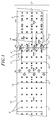
- FIG. 1 is a flat layout of the wall of the inner plenum 10 of the furnace.
- the plenum contains a series of gas restrictor walls 14 that may, in one embodiment, run perpendicular to the inner wall 21 and outer wall of the plenum and that, in the preferred embodiment, divide the inner chamber of the plenum 10 into four sectors or zones 1, 2, 3, and 4.
- the inner chamber of the plenum may have any number of zones that best suits the needs of the user.
- the plenum may be designed to have anywhere between two and eight zones, or it may even have more zones.
- a manufacturer needs to have a level of cooling along the bottom third of the load that is different from the top two-thirds, then a two zone plenum could be manufactured at a cost less expensive than that of a four or eight zone plenum.
- any number of gas restrictor walls 14 can be fixed, such as through welding to the inner wall 21 so as to create the necessary number of zones.
- the outer wall can then be assembled from pieces that, when fixed together, cover the span of each zone and have their edges fixed, such as through welding, to the top edges of the gas restrictor walls 14. Because pieces of the outer wall can be custom fit to any size, the gas restrictor walls 14 can connect to the inner wall 21 at any angle the manufacturer finds suitable.
- each zone contains a plurality of threaded tank flanges on the inner wall that serve as gas nozzles 5 to allow gas to flow into the plenum's inner chamber.
- Each of the secondary gas inlets corresponds to one zone so that gas 11 only flows from one gas inlet into only one zone.
- gas flowing through secondary gas inlet 1' only flows into zone 1; gas flowing through secondary gas inlet 2' only flows into its corresponding zone 2; gas flowing through secondary gas inlet 3' only flows into its corresponding zone 3; and gas flowing through secondary gas inlet 4' only flows into its corresponding zone 4.
- Gas 11 flows from each gas inlet and remains contained within the gas inlet's corresponding zone by the gas restrictor walls 14. Any gas that enters a zone flows through the zone's gas nozzles 5 that lead to the plenum's inner chamber.
- gas 11 flow from the inlets (e.g., 3') into each of the zones or chambers is depicted.
- FIG. 2b a perspective view of the portion of the inlet that lies between the inner and outer walls of the plenum is shown.
- the piping of each inlet 12 contains a 180-degree notch 13 so as to aid in the direction of the gas flow 11 into the chamber that constitutes a particular zone.
- the cooling gas 23 enters the furnace via a main gas inlet pipeline 15.
- the gas 104 reaches the gas inlet manifold 202 and is divided into four separate secondary gas inlet supplies 16.
- a valve 17 in each of the secondary gas inlet supplies 16 controls the flow of the gas.
- the valves 17 may each be opened or closed to varying degrees in order to regulate the amount of gas flowing through each secondary gas inlet that may reach the plenum 20.
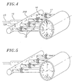
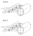
- FIG. 3 shows an alternate view of the process shown in FIG. 4.
- the cooling gas 23 is pumped into the furnace via a main gas inlet supply 15 in the gas manifold 201.
- the gas flow is divided into four secondary gas inlet supplies 16.
- a valve 17 in each of the secondary gas inlet supplies 16 controls the flow of the gas 203.
- the valves 17 may each be opened or closed to varying degrees in order to regulate the amount of gas flowing through each secondary gas inlet that may reach the plenum 20.
- the gas then flows within the cavity 18 between the inner wall 21 (which corresponds to the inner wall 21 in FIG. 1) and the outer wall 301 of the plenum 20.
- the gas is contained within its particular zone by the gas path restrictor walls 14, which correspond to the gas path restrictor walls 14 in FIG. 1.
- the gas then passes through the gas nozzles 5 of its particular zone 1, 2, 3, or 4 into the hot zone of the inner plenum 22.
- FIG. 3b a close-up version of one of the nozzles 5 from FIG. 3 is shown.
- the regulation of the valves is computerized allowing for computer modeling to determine the best sequence for a particular load.
- Thermo couples can be placed in the furnace, by themselves or with the load, so as to provide data feedback to the computer regarding temperature levels at different points.
- the computer can model the ideal cooling sequence for a particular load and can then automatically regulate the valve sequences for subsequent loads to provide optimal cooling.
- the secondary gas inlet supplies all enter the furnace along one side. Conveying the gas to the particular circumferential sector is handled by arranging the restrictor walls appropriately. This approach minimizes the amount of external piping and the foot print or floor space required for a furnace. However, the secondary gas inlet supplies could be configured to enter the furnace at or near the particular sectors with which they are each associated. This alternate approach would require additional external piping, but may simplify the arrangement of the restrictor walls. Either approach or some combination of both may be adopted as suitable for a particular situation.
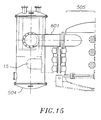
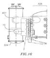
- FIGS. 13-16 show a preferred embodiment of the complete vacuum furnace from both the top and front views.
- an exit gas manifold 601 is connected to the plenum 505 and the gas supply 504. After gas enters the plenum and cools the load, it leaves the plenum through the exit gas manifold 601.
- the entire furnace 501 is supported by stands 502 and 503.
- a fan 506 turns to pump inert gas through the main piping manifold 15. This gas 23 travels up the manifold 15, which corresponds to the manifold 15 in FIG. 3, and enters the secondary gas manifolds and plenum 505, which correspond to the entirety of FIG. 3.
- FIG. 15 shows a top view, with some parts in phantom, of FIG. 13.
- FIG. 16 shows a top view, with different parts in phantom, of FIG. 14.
- the preferred embodiment of this invention provides directional cooling to the load in the plenum of the furnace and thus allows for different portions of the load to be cooled at different rates.
Landscapes
- Engineering & Computer Science (AREA)
- Chemical & Material Sciences (AREA)
- Mechanical Engineering (AREA)
- General Engineering & Computer Science (AREA)
- Physics & Mathematics (AREA)
- Thermal Sciences (AREA)
- Crystallography & Structural Chemistry (AREA)
- Materials Engineering (AREA)
- Metallurgy (AREA)
- Organic Chemistry (AREA)
- Furnace Details (AREA)
Applications Claiming Priority (1)
| Application Number | Priority Date | Filing Date | Title |
|---|---|---|---|
| US11/208,282 US7758339B2 (en) | 2005-08-18 | 2005-08-18 | Method and apparatus for directional and controlled cooling in vacuum furnaces |
Publications (3)
| Publication Number | Publication Date |
|---|---|
| EP1754944A2 true EP1754944A2 (de) | 2007-02-21 |
| EP1754944A3 EP1754944A3 (de) | 2008-04-09 |
| EP1754944B1 EP1754944B1 (de) | 2015-05-06 |
Family
ID=37450901
Family Applications (1)
| Application Number | Title | Priority Date | Filing Date |
|---|---|---|---|
| EP20060110788 Expired - Lifetime EP1754944B1 (de) | 2005-08-18 | 2006-03-07 | Verfahren und Vorrichtung zur gerichteten und kontrollierten Kühlung in Vakuumöfen |
Country Status (2)
| Country | Link |
|---|---|
| US (1) | US7758339B2 (de) |
| EP (1) | EP1754944B1 (de) |
Cited By (1)
| Publication number | Priority date | Publication date | Assignee | Title |
|---|---|---|---|---|
| CN102297602A (zh) * | 2011-08-08 | 2011-12-28 | 中国一拖集团有限公司 | 用于电炉水冷系统的差动切换应急处理装置及配置方法 |
Citations (3)
| Publication number | Priority date | Publication date | Assignee | Title |
|---|---|---|---|---|
| US4713124A (en) | 1983-06-22 | 1987-12-15 | Schmetz Gmbh & Co. Kg Unternehmensverwaltung | Method for cooling a charge after thermal treatment |
| JPH11153386A (ja) | 1997-11-25 | 1999-06-08 | Ishikawajima Harima Heavy Ind Co Ltd | 多室式マルチ冷却真空炉 |
| US6349108B1 (en) | 2001-03-08 | 2002-02-19 | Pv/T, Inc. | High temperature vacuum furnace |
Family Cites Families (14)
| Publication number | Priority date | Publication date | Assignee | Title |
|---|---|---|---|---|
| US2311350A (en) * | 1939-12-26 | 1943-02-16 | Richardson Edward Adams | Method and apparatus for controlling combustion |
| DE2839807C2 (de) * | 1978-09-13 | 1986-04-17 | Degussa Ag, 6000 Frankfurt | Vakuumofen mit Gaskühleinrichtung |
| US4395832A (en) * | 1981-01-02 | 1983-08-02 | Vacuum Furnace System Corporation | Gas duct arrangement for a vacuum furnace |
| US4490110A (en) * | 1983-05-20 | 1984-12-25 | Jones William R | Plenum arrangement |
| US4560348A (en) * | 1984-05-24 | 1985-12-24 | Abar Ipsen Industries | Gas nozzle for a heat treating furnace |
| US4643401A (en) * | 1985-08-28 | 1987-02-17 | Mg Industries | Apparatus for cooling a vacuum furnace |
| FR2614683B1 (fr) * | 1987-04-28 | 1989-06-16 | Bmi Fours Ind | Four de traitement thermique sous vide a refroidissement par courant de gaz |
| US4765068A (en) * | 1987-08-07 | 1988-08-23 | Vacuum Furnace Systems Corporation | Hot zone arrangement for a vacuum furnace |
| US5267257A (en) * | 1991-08-14 | 1993-11-30 | Grier-Jhawar-Mercer, Inc. | Vacuum furnace with convection heating and cooling |
| US5502742A (en) * | 1993-02-26 | 1996-03-26 | Abar Ipsen Industries, Inc. | Heat treating furnace with removable floor, adjustable heating element support, and threaded ceramic gas injection nozzle |
| US7089681B2 (en) * | 2002-11-26 | 2006-08-15 | Alkermes Controlled Therapeutics, Inc. | Method and apparatus for filtering and drying a product |
| EP2116802B1 (de) * | 2003-06-27 | 2011-01-12 | IHI Corporation | Vakuum-Wärmebehandlungsofen der Gaskühlungsart und Vorrichtung zum Wechseln der Richtung von Kühlgas |
| WO2006030504A1 (ja) * | 2004-09-16 | 2006-03-23 | Ishikawajima-Harima Heavy Industries Co., Ltd. | 真空熱処理炉の冷却ガス風路切替え装置 |
| US7514035B2 (en) * | 2005-09-26 | 2009-04-07 | Jones William R | Versatile high velocity integral vacuum furnace |
-
2005
- 2005-08-18 US US11/208,282 patent/US7758339B2/en not_active Expired - Fee Related
-
2006
- 2006-03-07 EP EP20060110788 patent/EP1754944B1/de not_active Expired - Lifetime
Patent Citations (3)
| Publication number | Priority date | Publication date | Assignee | Title |
|---|---|---|---|---|
| US4713124A (en) | 1983-06-22 | 1987-12-15 | Schmetz Gmbh & Co. Kg Unternehmensverwaltung | Method for cooling a charge after thermal treatment |
| JPH11153386A (ja) | 1997-11-25 | 1999-06-08 | Ishikawajima Harima Heavy Ind Co Ltd | 多室式マルチ冷却真空炉 |
| US6349108B1 (en) | 2001-03-08 | 2002-02-19 | Pv/T, Inc. | High temperature vacuum furnace |
Cited By (2)
| Publication number | Priority date | Publication date | Assignee | Title |
|---|---|---|---|---|
| CN102297602A (zh) * | 2011-08-08 | 2011-12-28 | 中国一拖集团有限公司 | 用于电炉水冷系统的差动切换应急处理装置及配置方法 |
| CN102297602B (zh) * | 2011-08-08 | 2013-08-21 | 中国一拖集团有限公司 | 用于电炉水冷系统的差动切换应急处理装置及配置方法 |
Also Published As
| Publication number | Publication date |
|---|---|
| US20070042309A1 (en) | 2007-02-22 |
| EP1754944A3 (de) | 2008-04-09 |
| US7758339B2 (en) | 2010-07-20 |
| EP1754944B1 (de) | 2015-05-06 |
Similar Documents
| Publication | Publication Date | Title |
|---|---|---|
| CA1129645A (en) | Batch coil annealing furnace baseplate | |
| EP2116802B1 (de) | Vakuum-Wärmebehandlungsofen der Gaskühlungsart und Vorrichtung zum Wechseln der Richtung von Kühlgas | |
| US6693263B2 (en) | Convection type brazing apparatus for metal workpieces | |
| US6903306B2 (en) | Directional cooling system for vacuum heat treating furnace | |
| JP6239384B2 (ja) | 圧力容器と圧力容器を冷却するための方法 | |
| US7507368B2 (en) | Hot air circulation furnace | |
| KR100697426B1 (ko) | 열적 프로파일 향상 대류로 | |
| CN214670270U (zh) | 调温设备 | |
| JP2001340958A (ja) | 金属製ワークピースのコンベクション式ろう付け方法およびその装置 | |
| EP2110020B1 (de) | Ofen und Verfahren zur Steuerung des Luftstroms und von Luftlecks zwischen zwei Kammern | |
| TWI781096B (zh) | 熱處理裝置 | |
| US8029865B2 (en) | Method for coating or heat treatment of blisks for aircraft gas turbines | |
| US20040055589A1 (en) | Baking oven | |
| US7758339B2 (en) | Method and apparatus for directional and controlled cooling in vacuum furnaces | |
| HRP20110976T1 (hr) | Peć koja je pogodna za uporabu kod postupaka galvano žarenja i galvanizacije metalne trake | |
| US4317290A (en) | Heat treatment apparatus | |
| US20250008964A1 (en) | Oven ventilation for convective cooking and drying of food | |
| JP2004036908A (ja) | 塗装焼付乾燥炉 | |
| JP4461343B2 (ja) | 給湯器付風呂装置 | |
| JP7548838B2 (ja) | 熱処理装置 | |
| US20230408084A1 (en) | Blown air heating system | |
| US20230400180A1 (en) | Gas burner | |
| US6572368B1 (en) | Method and apparatus for cooling a furnace | |
| CA2442643A1 (en) | Process and apparatus for inner wall toasting of casks for wine guard by hot air convection | |
| JP2025064635A (ja) | 熱風循環炉 |
Legal Events
| Date | Code | Title | Description |
|---|---|---|---|
| PUAI | Public reference made under article 153(3) epc to a published international application that has entered the european phase |
Free format text: ORIGINAL CODE: 0009012 |
|
| 17P | Request for examination filed |
Effective date: 20060315 |
|
| AK | Designated contracting states |
Kind code of ref document: A2 Designated state(s): AT BE BG CH CY CZ DE DK EE ES FI FR GB GR HU IE IS IT LI LT LU LV MC NL PL PT RO SE SI SK TR |
|
| AX | Request for extension of the european patent |
Extension state: AL BA HR MK YU |
|
| PUAL | Search report despatched |
Free format text: ORIGINAL CODE: 0009013 |
|
| RIC1 | Information provided on ipc code assigned before grant |
Ipc: C21D 1/613 20060101ALI20080222BHEP Ipc: F27B 5/16 20060101AFI20080222BHEP Ipc: F27D 9/00 20060101ALI20080222BHEP Ipc: C21D 1/667 20060101ALI20080222BHEP |
|
| AK | Designated contracting states |
Kind code of ref document: A3 Designated state(s): AT BE BG CH CY CZ DE DK EE ES FI FR GB GR HU IE IS IT LI LT LU LV MC NL PL PT RO SE SI SK TR |
|
| AX | Request for extension of the european patent |
Extension state: AL BA HR MK YU |
|
| 17Q | First examination report despatched |
Effective date: 20080821 |
|
| AKX | Designation fees paid |
Designated state(s): AT BE BG CH CY CZ DE DK EE ES FI FR GB GR HU IE IS IT LI LT LU LV MC NL PL PT RO SE SI SK TR |
|
| GRAP | Despatch of communication of intention to grant a patent |
Free format text: ORIGINAL CODE: EPIDOSNIGR1 |
|
| INTG | Intention to grant announced |
Effective date: 20141210 |
|
| GRAS | Grant fee paid |
Free format text: ORIGINAL CODE: EPIDOSNIGR3 |
|
| GRAA | (expected) grant |
Free format text: ORIGINAL CODE: 0009210 |
|
| AK | Designated contracting states |
Kind code of ref document: B1 Designated state(s): AT BE BG CH CY CZ DE DK EE ES FI FR GB GR HU IE IS IT LI LT LU LV MC NL PL PT RO SE SI SK TR |
|
| REG | Reference to a national code |
Ref country code: GB Ref legal event code: FG4D |
|
| REG | Reference to a national code |
Ref country code: CH Ref legal event code: EP |
|
| REG | Reference to a national code |
Ref country code: IE Ref legal event code: FG4D |
|
| REG | Reference to a national code |
Ref country code: AT Ref legal event code: REF Ref document number: 725996 Country of ref document: AT Kind code of ref document: T Effective date: 20150615 |
|
| REG | Reference to a national code |
Ref country code: DE Ref legal event code: R096 Ref document number: 602006045342 Country of ref document: DE Effective date: 20150618 |
|
| REG | Reference to a national code |
Ref country code: NL Ref legal event code: T3 |
|
| REG | Reference to a national code |
Ref country code: AT Ref legal event code: MK05 Ref document number: 725996 Country of ref document: AT Kind code of ref document: T Effective date: 20150506 |
|
| REG | Reference to a national code |
Ref country code: LT Ref legal event code: MG4D |
|
| PG25 | Lapsed in a contracting state [announced via postgrant information from national office to epo] |
Ref country code: ES Free format text: LAPSE BECAUSE OF FAILURE TO SUBMIT A TRANSLATION OF THE DESCRIPTION OR TO PAY THE FEE WITHIN THE PRESCRIBED TIME-LIMIT Effective date: 20150506 Ref country code: LT Free format text: LAPSE BECAUSE OF FAILURE TO SUBMIT A TRANSLATION OF THE DESCRIPTION OR TO PAY THE FEE WITHIN THE PRESCRIBED TIME-LIMIT Effective date: 20150506 Ref country code: PT Free format text: LAPSE BECAUSE OF FAILURE TO SUBMIT A TRANSLATION OF THE DESCRIPTION OR TO PAY THE FEE WITHIN THE PRESCRIBED TIME-LIMIT Effective date: 20150907 Ref country code: FI Free format text: LAPSE BECAUSE OF FAILURE TO SUBMIT A TRANSLATION OF THE DESCRIPTION OR TO PAY THE FEE WITHIN THE PRESCRIBED TIME-LIMIT Effective date: 20150506 |
|
| PG25 | Lapsed in a contracting state [announced via postgrant information from national office to epo] |
Ref country code: GR Free format text: LAPSE BECAUSE OF FAILURE TO SUBMIT A TRANSLATION OF THE DESCRIPTION OR TO PAY THE FEE WITHIN THE PRESCRIBED TIME-LIMIT Effective date: 20150807 Ref country code: AT Free format text: LAPSE BECAUSE OF FAILURE TO SUBMIT A TRANSLATION OF THE DESCRIPTION OR TO PAY THE FEE WITHIN THE PRESCRIBED TIME-LIMIT Effective date: 20150506 Ref country code: IS Free format text: LAPSE BECAUSE OF FAILURE TO SUBMIT A TRANSLATION OF THE DESCRIPTION OR TO PAY THE FEE WITHIN THE PRESCRIBED TIME-LIMIT Effective date: 20150906 Ref country code: BG Free format text: LAPSE BECAUSE OF FAILURE TO SUBMIT A TRANSLATION OF THE DESCRIPTION OR TO PAY THE FEE WITHIN THE PRESCRIBED TIME-LIMIT Effective date: 20150806 Ref country code: LV Free format text: LAPSE BECAUSE OF FAILURE TO SUBMIT A TRANSLATION OF THE DESCRIPTION OR TO PAY THE FEE WITHIN THE PRESCRIBED TIME-LIMIT Effective date: 20150506 |
|
| PG25 | Lapsed in a contracting state [announced via postgrant information from national office to epo] |
Ref country code: EE Free format text: LAPSE BECAUSE OF FAILURE TO SUBMIT A TRANSLATION OF THE DESCRIPTION OR TO PAY THE FEE WITHIN THE PRESCRIBED TIME-LIMIT Effective date: 20150506 Ref country code: DK Free format text: LAPSE BECAUSE OF FAILURE TO SUBMIT A TRANSLATION OF THE DESCRIPTION OR TO PAY THE FEE WITHIN THE PRESCRIBED TIME-LIMIT Effective date: 20150506 |
|
| REG | Reference to a national code |
Ref country code: DE Ref legal event code: R097 Ref document number: 602006045342 Country of ref document: DE |
|
| PG25 | Lapsed in a contracting state [announced via postgrant information from national office to epo] |
Ref country code: PL Free format text: LAPSE BECAUSE OF FAILURE TO SUBMIT A TRANSLATION OF THE DESCRIPTION OR TO PAY THE FEE WITHIN THE PRESCRIBED TIME-LIMIT Effective date: 20150506 Ref country code: SK Free format text: LAPSE BECAUSE OF FAILURE TO SUBMIT A TRANSLATION OF THE DESCRIPTION OR TO PAY THE FEE WITHIN THE PRESCRIBED TIME-LIMIT Effective date: 20150506 Ref country code: RO Free format text: LAPSE BECAUSE OF NON-PAYMENT OF DUE FEES Effective date: 20150506 Ref country code: CZ Free format text: LAPSE BECAUSE OF FAILURE TO SUBMIT A TRANSLATION OF THE DESCRIPTION OR TO PAY THE FEE WITHIN THE PRESCRIBED TIME-LIMIT Effective date: 20150506 |
|
| PLBE | No opposition filed within time limit |
Free format text: ORIGINAL CODE: 0009261 |
|
| STAA | Information on the status of an ep patent application or granted ep patent |
Free format text: STATUS: NO OPPOSITION FILED WITHIN TIME LIMIT |
|
| REG | Reference to a national code |
Ref country code: FR Ref legal event code: PLFP Year of fee payment: 11 |
|
| 26N | No opposition filed |
Effective date: 20160209 |
|
| PG25 | Lapsed in a contracting state [announced via postgrant information from national office to epo] |
Ref country code: IT Free format text: LAPSE BECAUSE OF FAILURE TO SUBMIT A TRANSLATION OF THE DESCRIPTION OR TO PAY THE FEE WITHIN THE PRESCRIBED TIME-LIMIT Effective date: 20150506 |
|
| PG25 | Lapsed in a contracting state [announced via postgrant information from national office to epo] |
Ref country code: SI Free format text: LAPSE BECAUSE OF FAILURE TO SUBMIT A TRANSLATION OF THE DESCRIPTION OR TO PAY THE FEE WITHIN THE PRESCRIBED TIME-LIMIT Effective date: 20150506 |
|
| PG25 | Lapsed in a contracting state [announced via postgrant information from national office to epo] |
Ref country code: BE Free format text: LAPSE BECAUSE OF FAILURE TO SUBMIT A TRANSLATION OF THE DESCRIPTION OR TO PAY THE FEE WITHIN THE PRESCRIBED TIME-LIMIT Effective date: 20150506 |
|
| PG25 | Lapsed in a contracting state [announced via postgrant information from national office to epo] |
Ref country code: LU Free format text: LAPSE BECAUSE OF FAILURE TO SUBMIT A TRANSLATION OF THE DESCRIPTION OR TO PAY THE FEE WITHIN THE PRESCRIBED TIME-LIMIT Effective date: 20160307 Ref country code: MC Free format text: LAPSE BECAUSE OF FAILURE TO SUBMIT A TRANSLATION OF THE DESCRIPTION OR TO PAY THE FEE WITHIN THE PRESCRIBED TIME-LIMIT Effective date: 20150506 |
|
| REG | Reference to a national code |
Ref country code: CH Ref legal event code: PL |
|
| REG | Reference to a national code |
Ref country code: IE Ref legal event code: MM4A |
|
| PG25 | Lapsed in a contracting state [announced via postgrant information from national office to epo] |
Ref country code: LI Free format text: LAPSE BECAUSE OF NON-PAYMENT OF DUE FEES Effective date: 20160331 Ref country code: IE Free format text: LAPSE BECAUSE OF NON-PAYMENT OF DUE FEES Effective date: 20160307 Ref country code: CH Free format text: LAPSE BECAUSE OF NON-PAYMENT OF DUE FEES Effective date: 20160331 |
|
| REG | Reference to a national code |
Ref country code: FR Ref legal event code: PLFP Year of fee payment: 12 |
|
| PG25 | Lapsed in a contracting state [announced via postgrant information from national office to epo] |
Ref country code: SE Free format text: LAPSE BECAUSE OF FAILURE TO SUBMIT A TRANSLATION OF THE DESCRIPTION OR TO PAY THE FEE WITHIN THE PRESCRIBED TIME-LIMIT Effective date: 20150506 |
|
| PG25 | Lapsed in a contracting state [announced via postgrant information from national office to epo] |
Ref country code: HU Free format text: LAPSE BECAUSE OF FAILURE TO SUBMIT A TRANSLATION OF THE DESCRIPTION OR TO PAY THE FEE WITHIN THE PRESCRIBED TIME-LIMIT; INVALID AB INITIO Effective date: 20060307 Ref country code: CY Free format text: LAPSE BECAUSE OF FAILURE TO SUBMIT A TRANSLATION OF THE DESCRIPTION OR TO PAY THE FEE WITHIN THE PRESCRIBED TIME-LIMIT Effective date: 20150506 |
|
| PG25 | Lapsed in a contracting state [announced via postgrant information from national office to epo] |
Ref country code: TR Free format text: LAPSE BECAUSE OF FAILURE TO SUBMIT A TRANSLATION OF THE DESCRIPTION OR TO PAY THE FEE WITHIN THE PRESCRIBED TIME-LIMIT Effective date: 20150506 |
|
| REG | Reference to a national code |
Ref country code: FR Ref legal event code: PLFP Year of fee payment: 13 |
|
| REG | Reference to a national code |
Ref country code: DE Ref legal event code: R082 Ref document number: 602006045342 Country of ref document: DE Representative=s name: HORN KLEIMANN WAITZHOFER PATENTANWAELTE PARTG , DE Ref country code: DE Ref legal event code: R081 Ref document number: 602006045342 Country of ref document: DE Owner name: JHAWAR INDUSTRIES, LLC, CORONA, US Free format text: FORMER OWNER: G-M ENTERPRISES, CORONA, CALIF., US |
|
| REG | Reference to a national code |
Ref country code: GB Ref legal event code: 732E Free format text: REGISTERED BETWEEN 20190509 AND 20190515 |
|
| REG | Reference to a national code |
Ref country code: NL Ref legal event code: HC Owner name: JHAWAR INDUSTRIES, INC.; US Free format text: DETAILS ASSIGNMENT: CHANGE OF OWNER(S), CHANGE OF OWNER(S) NAME; FORMER OWNER NAME: GRIER-JHAWAR INC. Effective date: 20190807 Ref country code: NL Ref legal event code: PD Owner name: JHAWAR INDUSTRIES, LLC; US Free format text: DETAILS ASSIGNMENT: CHANGE OF OWNER(S), CHANGE OF LEGAL ENTITY; FORMER OWNER NAME: JHAWAR INDUSTRIES, INC. Effective date: 20190807 |
|
| PGFP | Annual fee paid to national office [announced via postgrant information from national office to epo] |
Ref country code: DE Payment date: 20200429 Year of fee payment: 15 Ref country code: FR Payment date: 20200427 Year of fee payment: 15 Ref country code: NL Payment date: 20200426 Year of fee payment: 15 |
|
| PGFP | Annual fee paid to national office [announced via postgrant information from national office to epo] |
Ref country code: GB Payment date: 20200427 Year of fee payment: 15 |
|
| REG | Reference to a national code |
Ref country code: DE Ref legal event code: R119 Ref document number: 602006045342 Country of ref document: DE |
|
| REG | Reference to a national code |
Ref country code: NL Ref legal event code: MM Effective date: 20210401 |
|
| GBPC | Gb: european patent ceased through non-payment of renewal fee |
Effective date: 20210307 |
|
| PG25 | Lapsed in a contracting state [announced via postgrant information from national office to epo] |
Ref country code: NL Free format text: LAPSE BECAUSE OF NON-PAYMENT OF DUE FEES Effective date: 20210401 Ref country code: DE Free format text: LAPSE BECAUSE OF NON-PAYMENT OF DUE FEES Effective date: 20211001 Ref country code: FR Free format text: LAPSE BECAUSE OF NON-PAYMENT OF DUE FEES Effective date: 20210331 Ref country code: GB Free format text: LAPSE BECAUSE OF NON-PAYMENT OF DUE FEES Effective date: 20210307 |