EP1753691B1 - Assemblage de vannes dote d'un dispositif de positionnement pour tonneau muni d'un sac interieur - Google Patents
Assemblage de vannes dote d'un dispositif de positionnement pour tonneau muni d'un sac interieur Download PDFInfo
- Publication number
- EP1753691B1 EP1753691B1 EP05747571.7A EP05747571A EP1753691B1 EP 1753691 B1 EP1753691 B1 EP 1753691B1 EP 05747571 A EP05747571 A EP 05747571A EP 1753691 B1 EP1753691 B1 EP 1753691B1
- Authority
- EP
- European Patent Office
- Prior art keywords
- collar
- valve assembly
- beverage
- positioning means
- apron
- Prior art date
- Legal status (The legal status is an assumption and is not a legal conclusion. Google has not performed a legal analysis and makes no representation as to the accuracy of the status listed.)
- Expired - Lifetime
Links
Images
Classifications
-
- B—PERFORMING OPERATIONS; TRANSPORTING
- B67—OPENING, CLOSING OR CLEANING BOTTLES, JARS OR SIMILAR CONTAINERS; LIQUID HANDLING
- B67D—DISPENSING, DELIVERING OR TRANSFERRING LIQUIDS, NOT OTHERWISE PROVIDED FOR
- B67D1/00—Apparatus or devices for dispensing beverages on draught
- B67D1/08—Details
- B67D1/0829—Keg connection means
- B67D1/0831—Keg connection means combined with valves
-
- B—PERFORMING OPERATIONS; TRANSPORTING
- B67—OPENING, CLOSING OR CLEANING BOTTLES, JARS OR SIMILAR CONTAINERS; LIQUID HANDLING
- B67D—DISPENSING, DELIVERING OR TRANSFERRING LIQUIDS, NOT OTHERWISE PROVIDED FOR
- B67D1/00—Apparatus or devices for dispensing beverages on draught
- B67D1/08—Details
- B67D1/0801—Details of beverage containers, e.g. casks, kegs
- B67D2001/0827—Bags in box
- B67D2001/0828—Bags in box in pressurised housing
Definitions
- the present invention relates to a beverage valve assembly and a beverage valve assembly arranged at a container with an inner bag for receiving beverage, in particular carbonated beverage such as beer. Further, the present invention is directed to a connecting element for engaging a beverage valve assembly. The present invention is further directed to a tapping device comprising a connecting element. The present invention is also directed to a beverage tapping apparatus comprising a replaceable container with a beverage valve assembly releasably engaged with a connecting element of a tapping device as well as to a method for dispensing beer from a beverage tapping apparatus.
- a valve assembly for use in beverage containers with an inner bag for receiving beverage is described in WO-A1 03/050031 .
- a valve assembly of a container is described in which an inner bag is provided for receiving beverage, in particular carbonated beverage such as beer, wherein a beverage valve is provided which on the side facing the inner bag is provided with an interface with the inner space of the bag and on the opposite side with means for operation of the beverage valve by a tapping device in which the container can be accommodated , wherein the beverage valve, on said opposite side, is surrounded by a standing first apron which is gas-tight, while along the outer side of said first apron, at a distance therefrom, a second apron is arranged, which is also gas-tight, while between the first and the second apron a bottom wall with at least one gas passage opening is provided which during operation is in communication with the space enclosed between the inner bag and a container surrounding the inner bag, the arrangement being such that during operation a collar
- a drawback of the valve assembly of WO-A1 03/050031 resides in that the first apron as well as the second apron are in an upright position, and thus can be damaged if the connecting element is displaced when the parts are attached to each other, so that during operation the collar of said connecting element does not abut against the second apron in a gastight and liquid-tight manner.
- the aprons are fragile, a displacement when they are attached to each other can easily cause twisting or even breakage of the first and/or the second apron, leading to leakage.
- the dispensing element abuts in a gastight and liquid-tight manner against the first apron only, so that damage as described above leads to gas and liquid leakage. Furthermore, a gastight and liquid-tight sealing is provided only for the first apron to the dispensing element and for the second apron to the collar of the connecting element. Therefore, leakage of at least only one apron leads to a malfunction of the entire valve assembly. Moreover, if the dispensing element is not in place, gas and liquid leakage occurs at the first apron as a result of gas and liquid leakage from the chamber formed between the first and second apron.
- US 3,908,861 A discloses a series tapper assembly and method for interconnecting a plurality of beer kegs or the like in series for a large volume outlet, whereby all of said kegs can be "tapped” in sequence at the same time and will be emptied of their contents in sequence during operation.
- First and second kegs are provided, each having a keg adapter mounted in an opening in a wall of the keg.
- a tapper is in operative engagement with each keg adaptor.
- Each tapper and associated keg adapter provide an inlet passageway for the transfer of fluid from outside to inside the keg, and an outlet passageway for the transfer of fluid from inside to outside the keg.
- US 3,913,608 A discloses a valve member containing controlled gas and liquid passageways for admitting gas into a keg and for dispensing liquid therefrom through a relatively small opening, wherein the valve member is mounted on the inside of the keg in alignment with said opening.
- a tapper connector member is mounted on the outside of the keg and is connected to and in operative relationship with the valve member.
- US 3,758,008 A discloses a keg adapter for beer kegs and the like with gas and liquid passageways containing normally closed valves, which when opened permit compressed gas to be admitted to the keg and beer to be withdrawn therefrom, said valves being biased toward the closed position by actuators which contain permanent magnets.
- valve assemblies for kegs are known from WO 00/76907 A1 and from NL 1 014 081 C2 .
- the object of the invention is to provide a valve assembly, in which at least most of the disadvantages mentioned have been avoided. More in particular, the object of the invention is to provide a valve assembly for containers with an inner bag, permitting a gas-tightly and liquid-tight connecting dispensing element to be safely connected to a beverage valve arrangement in a gastight and liquid-tight manner.
- a first object of the invention is to provide a beverage valve assembly according to claim 1, in which at least most of the disadvantages mentioned have been avoided.
- a beverage valve assembly comprising:
- the outer standing apron can be used during operation to abut against a first collar of a connecting element in a gastight and liquid-tight manner.
- a first collar of a connecting element can abut, in a gastight and/or liquid-tight manner , against the first sealing surface of the inner side of said apron.
- the tubular part of the beverage valve assembly has an upper inner tubular wall section with at least two sealing surfaces.
- the structural measurements of the specially designed sealing surfaces arranged at the upper inner tubular wall section provide that a second collar of a connecting element can abut against the second sealing surface of the inner tubular part in a gastight and liquid-tight manner, while a dispensing element can abut against the third sealing surface of the inner tubular part in a gastight and liquid-tight manner.
- the beverage valve assembly according to the present invention has the advantage that even a displacement of the connecting element with respect to the beverage valve assembly cannot damage a sealing component, so that a displacement does not lead to gas and liquid leakage. Furthermore, a gastight and liquid-tightseal is provided inside the inner tubular wall section by at least said second collar of the connecting element, which abuts against the second sealing surface of the inner tubular part in a gastight and liquid-tight manner and by said dispensing element which abuts against the third sealing surface of the inner tubular part in a gastight and liquid-tight manner.
- valve assembly according to the present invention can provide a releasable connection of the connecting dispensing element to the beverage valve arrangement.
- valve assembly according to the present invention can simultaneously provide gastight and liquid-tight sealing of the connecting dispensing element to the beverage valve arrangement in order to provide at the same time a separate gas passage and beverage passage.
- valve assembly can provide gastight and liquid-tight sealing of the connecting dispensing element to the beverage valve arrangement, whereby the beverage passage is sealed in a gastight and liquid-tight manner with respect to the gas chamber before the chamber of the gas passage is sealed in a gastight and liquid-tight manner.
- valve assembly can provide that the air- or CO 2 -valve is not accidentally pushed open during operation if the seals of a dispensing element connected to the beverage valve arrangement are displaced.
- the beverage valve assembly according to the present invention can comprise at least one positioning means with at least one opening in the form of a gap, preferably a vertical gap. At least one positioning means with an opening and/or an opening between at least two positioning means according to the present invention can be arranged along the inner sidewall section of said apron and at a distance therefrom, at least one positioning means preferably being a standing wall, more preferably the positioning means being a standing wall surrounding the top opening of the tubular part. Most preferably, at least one positioning means with an opening and/or an opening between at least two positioning means according to the present invention has an annular shape or the form of a ring.
- two positioning means form a ring, and openings are formed at two positions between the two positioning means , which openings can be located parallel to each other and more preferably the openings have the form of a vertical gap.
- three, four or at least five positioning means are arranged on the bottom of the beverage valve assembly, wherein at least one positioning means has at least one opening and/or at least one opening is arranged between at least two positioning means , which openings can , but need not be located parallel to each other, and more preferably the openings have the form of a vertical gap.
- the two positioning means have the same form. However, the positioning means can differ from each other.
- the four positioning means are separated by an opening between them.
- the number of positioning means and openings are limited only by the fact that in any case the outer side surface of at least one positioning means is larger than the outer side surface of at least one opening of said positioning means and/or of at least one opening between two positioning means.
- the beverage valve assembly according to the present invention can comprise at least one positioning means with an outer side surface in the range of > 0.5 cm 2 and ⁇ 30 cm 2 , preferably > 1 cm 2 and ⁇ 20 cm 2 , more preferably > 0 cm 2 and ⁇ 15 cm 2 and most preferably > 0 cm 2 and ⁇ 12 cm 2 .
- outer side surface means the outer upper side surface
- At least one positioning means is used to ensure that the connecting element cannot be displaced, thus, the positioning means serves as a guiding means. Further, at least one positioning means is used to ensure that the tubular dispensing element of a beverage dispensing system engages into the tubular part of the beverage valve assembly, and thus cannot be displaced.
- At least one positioning means with an opening and/or an opening between at least two positioning means according to the present invention does not have a sealing function but a guiding function to ensure that the connecting element properly fits to the beverage valve assembly at the time of connection and use.
- At least one positioning means with an opening and/or an opening between at least two positioning means of the beverage valve assembly according to the present invention can engage (can an opening engage) into the recess formed between the first and second collar of the connecting element.
- the thickness and width of at least one positioning means is chosen so that it fits into the recess of said connecting element when the beverage valve assembly and the connecting element are properly connected to each other.
- the at least one positioning means according to the present invention does not abut against at least a sidewall section of the first collar, nor against at least a sidewall section of the second collar and/or against at least a bottom wall section of the recess of the connecting element.
- the beverage valve assembly according to the present invention comprises at least one apron, however, in its most preferred form it comprises one apron.
- the inner sidewall section of the apron serves as a first sealing surface, so that a connecting element is able to abut, in a gastight and liquid-tight manner, against the first sealing surface of the inner sidewall section of said apron.
- the apron is concentrically arranged, so that it can be engaged internally by a collar of the connecting element.
- the collar preferably the first collar, comprises a recess, so that the apron engages and abuts against the recess of the first collar in a gastight and liquid-tight manner.
- a construction is preferred in which the inner sidewall section of the apron of the beverage valve assembly functions as a first sealing surface, so that an outer sidewall of a connecting element is able to abut, in a gastight and liquid-tight manner, against the first sealing surface of the inner sidewall section of said apron.
- the apron and at least one positioning means with an opening and/or an opening between at least two positioning means of the beverage valve assembly according to the present invention is preferably arranged concentrically with respect to the top opening.
- a concentric arrangement provides, among other advantages, a better gastight and liquid-tight sealing of the apron of the beverage valve assembly against the first collar of the connecting element.
- a concentric arrangement of at least one positioning means with an opening and/or an opening between at least two positioning means according to the present invention allows improved assembly of the beverage valve assembly with the connecting element and reduces or avoids the danger of a displacement associated with leakage.
- a concentric arrangement of at least one positioning means with an opening and/or an opening between at least two positioning means according to the present invention can provide that the air-valve and/or CO 2 -valve is not accidentally pushed open during operation, because a displacement of the dispensing element is avoided.
- the inner tubular part of the beverage valve assembly according to the present invention comprises preferably at least one sealing surface, and more preferably at least a first sealing surface and a second sealing surface.
- Said first sealing surface can be arranged flush with 1, above or below the upper outer surface of the bottom wall section of the beverage valve assembly.
- the sealing surface(s) of the inner tubular wall section is (are) annularly shaped. More preferably, the first sealing surface is annularly shaped.
- the inner tubular wall section of said upper tubular part has at least two sealing surfaces, which are preferably annularly shaped.
- the diameter of the opening of the tubular part within the annularly shaped first step or first shoulder is substantially larger than the diameter of the opening of the tubular part within the annularly shaped second step or second shoulder.
- a beverage valve can be arranged, for example to control the beverage flow.
- the bottom wall of the beverage valve assembly can comprise two valves, of which preferably one valve is connected to the passage to the space between the keg and the bag and the other valve is connected to the passage to the inner part of the bag, and more preferably the valve connected to the passage to the space between the keg and the bag is an air valve and/or the valve connected to the passage to the inner part of the bag is a CO 2 -valve, and preferably the valves are radially spaced apart, located on the same normal to the circle and equidistant from the center point, and they are arranged in the bottom wall section between the inner wall section of said outer apron and the opening of the tubular part or within the bottom wall section between the inner wall section of said outer apron and the outer wall section of said at least one inner positioning means according to the present invention.
- the internal diameter of the standing apron can be 10 mm to 100 mm, preferably 20 mm to 60 mm, and more preferably 30 mm to 50 mm; and the height of the apron measured from the upper outer surface of the bottom adjacent to the apron can be 0.5 mm to 50 mm, preferably 3 mm to 30 mm, and more preferably 5 mm to 25 mm; and the thickness of the apron is 0.1 mm to 15 mm, preferably 0.5 mm to 10 mm, and more preferably 1 mm to 5 mm.
- the internal diameter of at least one standing positioning means according to the present invention can be 0.5 mm to 50 mm, preferably 5 mm to 30 mm, and more preferably 10 mm to 25 mm; and the height of at least one positioning means according to the present invention, measured from the upper outer surface of the bottom adjacent to he apron, can be 0.5 mm to 50 mm, preferably 3 mm to 30 mm, and more preferably 5 mm to 25 mm; and the thickness of at least one positioning means according to the present invention can be 0.1 mm to 15 mm, preferably 0.5 mm to 10 mm, and more preferably 1 mm to 5 mm.
- the diameter of the top opening of the apron facing away from the bottom wall can be 0.5 mm to 50 mm, preferably 3 mm to 30 mm, and more preferably 5 mm to 25 mm; and/or the diameter of the top opening of at least one positioning means according to the present invention facing away from the bottom wall can be 0.5 mm to 50 mm, preferably 3 mm to 30 mm, and more preferably 5 mm to 25 mm.
- the internal diameter of the top opening of the tubular part and/or the diameter of the opening within the annularly shaped first step or first shoulder of the tubular part can be 0.5 mm to 50 mm, preferably 3 mm to 30 mm, and more preferably 5 mm to 25 mm; and/or the diameter of the opening within the annularly shaped second step or second shoulder of the tubular part can be 0.5 mm to 50 mm, preferably 3 mm to 30 mm, and more preferably 5 mm to 25 mm.
- the width of the upper outer surface of the annularly shaped first step or first shoulder can be 0.5 mm to 50 mm, preferably 3 mm to 30 mm, and more preferably 5 mm to 25 mm; and/or the width of the upper outer surface of the annularly shaped second step or second shoulder can be 0.5 mm to 50 mm, preferably 3 mm to 30 mm, and more preferably 5 mm to 25 mm.
- the difference in altitude between the upper outer surface of the annularly shaped first step or first shoulder and the upper outer surface of the annularly shaped second step or second shoulder can be 0.1 mm to 50 mm, preferably 1 mm to 25 mm, and more preferably 2 mm to 20 mm.
- a second object of the present invention is related to a connecting element.
- it relates to a connecting element for engaging a beverage valve assembly.
- the connecting element is used for engaging a beverage valve assembly in order to provide a separate gas and beverage passage.
- the connecting element can comprise a first outer collar and a second inner collar.
- the first and the second collar of the connecting element preferably have a circular shape. It is preferred that the first outer collar has at least one gas passage opening and/or the second inner collar has a continuous opening for receiving a dispensing element.
- the first outer collar and/or the second inner collar can be arranged, preferably concentrically, at a distance from each other. Between the first outer collar and the second inner collar a recess, preferably concentrically arranged, can be formed.
- a connecting element for engaging with a beverage valve assembly comprises preferably a first collar and a second collar, wherein between the first and the second collar a recess with a bottom wall is formed.
- the shape of the recess can be such that at least one positioning means according to the present invention can engage into the recess, while at least one positioning means does not contact the bottom wall and/or a sidewall of the recess if it fits properly.
- the form of at least one positioning means can be designed in such a way that at least one positioning means contacts the bottom wall and/or a sidewall of the recess.
- the recess does not abut, in a gastight and liquid-tight manner, against an outer sidewall of at least one positioning means.
- the second inner collar can project above the first outer collar. This has the advantage that the second inner collar can engage into the tubular part of the beverage valve assembly, said second collar preferably being concentrically arranged.
- the height of the second inner collar is adjusted so that it abuts against the first sealing surface of the inner tubular part of the beverage valve assembly in a gastight and liquid-tight manner, when the connecting element and the beverage valve assembly are releasably joined to each other.
- the connecting element and the beverage valve assembly are removably interconnected.
- the first collar and/or the second collar can have at least one hole for a gas passage. However, it is most preferred that the first outer collar has one continuous hole, also referred to as "throughhole" only for a gas passage. Air under pressure can flow through this gas passage.
- the first collar of the connecting element should be connected to the beverage valve assembly in such a way that a gas passage from the throughhole of the first collar to the passage to the space between the keg and the bag is formed via the gas-valve.
- the second collar has at least one continuous hole, also called “through hole” through which the dispensing element is passed.
- the "throughhole” of the second collar is arranged in the center of the second collar.
- the second collar with a throughhole in the center can have a step at the upper section of the opening of said throughhole onto which the dispensing element can be held.
- the connecting element and the beverage valve assembly can be removably interconnected in such a way that during operation a first collar of the connecting element according to the present invention abuts , in a gastight and liquid-tight manner, against the first sealing surface of the inner side of the apron of the beverage valve assembly, whereby a gas chamber can be formed and a second collar of said connecting element abuts, in a gastight and liquid-tight manner, against the second sealing surface of the tubular part of the beverage valve assembly.
- a gas chamber is formed, if the top of the surface of the first collar does not contact, or only partly contacts, the bottom wall section between the apron and at least one positioning means according to the present invention or tubular part of the beverage valve assembly.
- the second collar which abuts against the second sealing surface of the tubular part in a gastight and liquid-tight manner can also seal the gas chamber.
- the second inner collar provides a "throughhole" for receiving a dispensing element.
- the throughhole of the second inner collar of the connecting element is preferably arranged in the center of the second collar. While a dispensing element abuts against the third sealing surface of the inner tubular part in a gastight and liquid-tight manner, the connecting element is positioned so that the gas passage opening of the first collar is in communication with the gas valve, so that gas under pressure can be forced through said at least one gas passage opening, separately from the beverage.
- first outer collar of the connecting element can provide at its upper outer surface, preferably at or near to the outer edge of its upper outer surface, at least one flexible sealing means; and/or the second inner collar of the connecting element can provide at its upper outer surface, preferably at or near to the outer edge of its upper outer surface, at least one flexible sealing means.
- the flexible sealing means can be an o-ring or any other flexible sealing material.
- the sealing material can be rubber, Teflon or the like.
- connection element according to the present invention. It is noted that the actual dimensions of the connecting element are adjusted in such a way that the connecting element fits, most preferably replaceably fits, to the beverage valve assembly as well as to dispensing element during use, without causing a malfunction.
- data is selected from the ranges given below, in such a way that a proper fit to the other parts described, such as the beverage valve assembly, the dispensing element etc., is assured without causing a malfunction. In other words, the ranges given below are selected so that the connecting element fits properly.
- the internal diameter of the first outer collar can be 1 mm to 100 mm, preferably 20 mm to 60 mm, and more preferably 30 mm to 50 mm; and the height of the first outer collar, as measured from the bottom of the recess adjacent to the first outer collar, can be 0 mm to 50 mm, preferably 5 mm to 30 mm, and more preferably 10 mm to 25 mm; and the thickness of the first outer collar can be 0.1 mm to 30 mm, preferably 1 mm to 20 mm, and more preferably 2 mm to 15 mm.
- the internal diameter of the second inner collar can be 0.1 mm to 50 mm, preferably 2 mm to 35 mm, and more preferably 5 mm to 25 mm; and the height of the second inner collar, as measured from the bottom of the recess adjacent to the second inner collar, can be 0 mm to 50 mm, preferably 2 mm to 40 mm, and more preferably 5 mm to 30 mm; and the thickness of the second inner collar can be 0.1 mm to 15 mm, preferably 0.2 mm to 10 mm, and more preferably 0.5 mm to 5 mm.
- the internal diameter of the top opening of the first inner collar facing the beverage valve assembly can be 0.1 mm to 50 mm, preferably 2 mm to 35 mm, and more preferably 5 mm to 25 mm; and/or the internal diameter of the top opening of the throughhole of the second inner collar facing the beverage valve assembly can be 0.1 mm to 50 mm, preferably 2 mm to 35 mm, and more preferably 5 mm to 25 mm.
- the distance from the inner sidewall of the first collar to the outer sidewall of the second collar can be 0.5 mm to 50 mm, preferably 2 mm to 20 mm, and more preferably 5 mm to 15 mm.
- a third object according to the present invention relates to a tapping device.
- the tapping device comprises a connecting element according to the present invention.
- the tapping device according to the present invention is provided with means for operation of a beverage valve assembly to which a container is releasably engaged.
- the second inner collar of the connecting element of said tapping device has a throughhole for receiving the tubular dispensing element.
- the tubular dispensing element can abut against the third sealing surface of the inner tubular part in a gastight and liquid-tight manner.
- the tubular dispensing element can be a cartridge unit with an inner channel or pipe for the dispensation of a beverage.
- That cartridge unit can comprise preferably a first part, facing the container, which is made of a rigid material, and a second part, facing in the opposite direction, which is made of a flexible material.
- the tubular dispensing element of the cartridge unit projects above the second inner collar.
- the tubular dispensing element of the cartridge unit extends over the inner edge of the top opening of the second collar facing the beverage valve assembly.
- the height of the tubular dispensing element can be ⁇ 0 mm to 100 mm, preferably 5 mm to 60 mm, and more preferably 20 mm to 50 mm.
- a fourth object according to the present invention relates to a beverage valve assembly according to the present invention arranged on a container in which an inner bag is provided for receiving beverage, in particular carbonated beverage such as beer.
- the beverage valve assembly is arranged on said container, and a connecting element or a tapping device as already described can be fitted to said beverage valve assembly during operation..
- the beverage valve assembly according to the present invention is designed in such a way that during operation a first collar of the connecting element abuts , in a gastight and liquid-tight manner, against the first sealing surface of the inner side of said apron, and/or a second collar of said connecting element abuts , in a gastight and liquid-tight manner, against the second sealing surface of the tubular part, and/or a dispensing element abuts , in a gastight and liquid-tight manner, against the third sealing surface of the inner tubular part.
- the beverage valve assembly On the side facing the inner bag, the beverage valve assembly is provided with a gas passage opening to the inner space of the bag and on the opposite side it is surrounded by an outer standing apron which is gas-tight, while along the inner sidewall of said apron, which functions as a first sealing surface, and at a distance therefrom at least one inner positioning means according to the present invention is arranged, and between said apron and said at least one positioning means with an opening and/or an opening between at least two positioning means a bottom wall with at least one gas valve is provided which during operation is in communication with the space enclosed between the inner bag and the container surrounding the inner bag via a gas passage, and a tubular part for receiving a dispensing element is arranged in the center, optionally surrounded by a standing p positioning means with an opening and/or an opening between at least two positioning means, which inner tubular part comprises a second sealing surface and a third sealing surface, the valve assembly being such that during operation a first collar of a connecting element according to the present invention
- a fifth object according to the present invention relates to a beverage tapping apparatus.
- the beverage tapping apparatus comprises a replaceable container with a beverage valve assembly according to the present invention releasably engaged with a connecting element of a tapping device according to the present invention, wherein the beverage valve assembly is provided on the side facing the inner bag with a gas passage opening to the inner space of the bag and on the opposite side is surrounded by an outer standing apron which is gas-tight, while along the inner sidewall of said apron, which functions as a first sealing surface, and at a distance therefrom at least one inner positioning means with an opening and/or an opening between at least two positioning means is arranged, and between said apron and said at least one positioning means a bottom wall with at least one gas valve is provided which during operation is in communication with the space enclosed between the inner bag and the container surrounding the inner bag via a gas passage, and a tubular part for receiving a dispensing element is arranged in the center, optionally surrounded by at least one standing positioning means with an opening and/or an opening between at least two positioning means, which positioning
- the tapping apparatus can comprise pressure means and/or chiller means. It is preferred that the tapping device with the connecting element is arranged on the beverage valve assembly, which is arranged on the container with an inner bag containing the beverage, so that the tapping apparatus functions as a housing for replaceably accommodating the tapping device with the connecting element arranged on the beverage valve assembly, which is arranged on the container with an inner bag containing the beverage.
- first sealing surface is an inner wall section of the apron and the second and third sealing surfaces are an inner wall section of the tubular part of the beverage valve assembly.
- first-, second- and third sealing surfaces are mentioned.
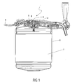
- FIG. 1 shows in a sectional side elevation a beverage tapping apparatus (1) according to the present invention with a tapping device (2) and a dispensing element (3), wherein the tapping device with the connecting element (4) is releasably joined to the beverage valve assembly (5) connected to a container (6) in which an inner bag (7) is provided for receiving beverage.
- the container can be placed on a chiller plate, not shown.
- the tapping device can be connected to pressure means (8).
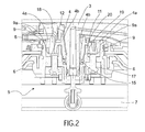
- FIG. 2 shows a cutout of the sectional side elevation of Fig. 1 in which the beverage valve assembly (5) according to the present invention is arranged on a container (6) in which an inner bag (7) is provided for receiving beverage, such as beer.
- the beverage valve assembly (5) is provided on the side facing the inner bag (7) with a gas passage opening (10) to the inner space of the bag (7) and on the opposite side is surrounded by an outer standing apron (9) which is gas-tight, while along the inner sidewall of said apron (9), which functions as a first sealing surface (9a), and at a distance therefrom, an inner circular positioning means (11) with a vertical gap (24) (not shown) is arranged, while between said apron (9) and said positioning means (11) a bottom wall (12) with a gas valve (13) and a CO 2 -valve (17) are arranged, which gas valve (13), during operation, is in communication with the space enclosed between the inner bag (7) and the container (8) surrounding the inner bag via a gas
- the valve assembly (5) is assembled such that during operation a first collar (4a) of a connecting element (4) abuts, in a gastight and liquid-tight manner, against the first sealing surface (9a) of the inner side of said apron (9) and a second collar (4b) of said connecting element (4) abuts , in a gastight and liquid-tight manner, against the second sealing surface (15) of the tubular part (14), while a dispensing element (3) abuts against the third sealing surface (6) of the inner tubular part (14) in a gastight and liquid-tight manner, the connecting element (4) being positioned in such a way that the gas passage opening (18) of the first collar (4a) is in communication with the gas valve (13), so that gas under pressure can be forced through said at least one gas passage opening (10), separately from the beverage.
- the connecting element (4) as described above comprises a first collar (4a) and a second collar (4b), a recess (19) with a recess bottom (20) into which a circular positioning means (11) with a vertical gap (24) (not shown) engages being situated between the first collar (4a) and the second collar (4b) .
- the second collar (4b) of the connecting element (4) has a throughhole in the center through which the dispensing element (3) is passed.
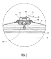
- FIG. 3 shows in a sectional side elevation a beverage valve assembly (5) according to the present invention arranged on a container (6) in which an inner bag (7) is provided for receiving beverage, such as beer.
- the beverage valve assembly (5) is provided on the side facing the inner bag (7) with a gas passage opening (10) (not shown) to the inner space of the bag (7) and on the opposite side is surrounded by an outer standing apron (9) which is gas-tight, while along the inner sidewall of said apron, which functions as a first sealing surface, and at a distance therefrom, an inner circular positioning means (11) with a vertical gap (24) is arranged, and between said apron (9) and said positioning means (11) with a vertical gap (24), a bottom wall (12) with at least one gas valve (13) and at least one CO 2 -valve (17) is provided which, during operation, is in communication with the space enclosed between the inner bag and the container surrounding the inner bag via a gas passage, a tubular part (14) for receiving a
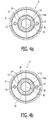
- Fig. 4a shows in a top-side sectional side elevation a beverage valve assembly (5) with a bottom wall (12), a tubular part (14) extending downward from the bottom wall (12) and an outer circular apron (9) extending upward from the bottom wall (12), wherein the tubular part (14) has a top opening (21) to receive a dispensing element (3), which top opening (21) is preferably arranged in the middle section of the upper outer surface of the bottom wall (12), and the tubular part (14) has an upper inner tubular wall section with at least one sealing surface, wherein an upper section of the inner tubular part is step and/or shoulder- shaped (14a) (not shown), and the outer standing apron (9) is arranged at a distance from the top opening (21) of the tubular part (14), wherein the bottom wall (12) comprises a gas-valve (13) and a CO 2 -valve (17) positioned between the top opening (21) of the tubular part (14) and an inner sidewall section of the outer standing apro
- Fig. 4b shows in a top-side sectional side elevation a beverage valve assembly (5) with a bottom wall (12), a tubular part (14) extending downward from the bottom wall (12) and an outer circular apron (9) extending upward from the bottom wall (12), wherein the tubular part (14) has a top opening (21) to receive a dispensing element (3), which top opening (21) is preferably arranged in the middle section of the upper outer surface of the bottom wall (12), and the tubular part (14) has an upper inner tubular wall section with at least one sealing surface, wherein an upper section of the inner tubular part is step and/or shoulder- shaped (14a) (not shown), and the outer standing apron (9) is arranged at a distance from the top opening (21) of the tubular part (14), wherein the bottom wall (12) comprises a gas-valve (13) and a CO 2 -valve (17) positioned between the top opening (21) of the tubular part (14) and an inner sidewall section of the outer standing up a
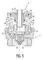
- FIG. 5 shows in a sectional side elevation a beverage valve assembly (5) and a connecting element (4) according to the present invention before they are joined to each other.
- the beverage valve assembly (5) has a bottom wall (12), a tubular part (14) extending downward from the bottom wall (12) and an outer circular apron (9) extending upward from the bottom wall (12), wherein the tubular part (14) has a top opening (21) to receive a dispensing element (3), which top opening (21) is preferably arranged in the middle section of the upper outer surface of the bottom wall (12), and the tubular part (14) has an upper inner tubular wall section with a second sealing surface (15) and third sealing surface (16), and the outer circular standing apron (9) with a first sealing surface (9a) is arranged at a distance from the top opening (21) of the tubular part (14), wherein the bottom wall (12) comprises a gas-valve (13) and a CO 2 -valve (17) positioned between the top opening (21) of the tubular part (14) and an
- the connecting element (4) as described above comprises a first collar (4a) and a second collar (4b) with a throughhole (22) in the center through which the dispensing element (3) is passed, wherein between the first collar (4a) and the second collar (4b) a recess (19) with a recess bottom (20) is formed into which a circular positioning means (11) with a vertical gap (24) (not shown) can engage.
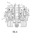
- Fig. 6 shows in a sectional side elevation a beverage valve assembly (5) and a connecting element (4) according to the present invention, which are joined to each other.
- the beverage valve assembly (5) according to the present invention is arranged on a container (6) in which an inner bag (7) is provided for receiving beverage (not shown), such as beer.
- the beverage valve assembly (5) is provided on the side facing the inner bag (7) with a gas passage opening (10) to the inner space of the bag (7) and on the opposite side is surrounded by an outer standing apron (9) which is gas-tight, while along the inner sidewall (9a) of said apron (9), which functions as a first sealing surface (9a), and at a distance therefrom, an inner circular positioning (11) means is arranged, and between said apron (9) and said positioning means (11) with a vertical gap (24) (not shown) a bottom wall (12) with a gas valve (13) and a CO 2 -valve (17) are arranged, which gas valve (13), during operation, is in communication with the space enclosed between the inner bag (7) and the container (8) surrounding the inner bag via a gas passage (10), wherein a tubular part (14) for receiving a dispensing element (3) is arranged in the center of the beverage valve assembly (5), surrounded by the standing positioning means (11) with a vertical gap (24) (not shown), which inner tubular
- the valve assembly (5) is assembled such that during operation a first collar (4a) of a connecting element (4) abuts against the first sealing surface (9a) of the inner side of said apron (9), in a gastight and liquid-tight manner, and a second collar (4b) of said connecting element (4) with a throughhole (22) in the center through which the dispensing element (3) is passed abuts , in a gastight and liquid-tight manner, against the second sealing surface (15) of the tubular part (14), while a dispensing element (3) abuts , in a gastight and liquid-tight manner, against the third sealing surface (16) of the inner tubular part (14), the connecting element (4) being positioned in such a way that the gas passage opening (18) (not shown) of the first collar (4a) is in communication with the gas valve (13), so that gas under pressure can be forced through said at least one gas passage opening (10), separately from the beverage.
- the connecting element (4) as described above comprises a first collar (4a) and a second collar (4b) with a throughhole (22) in the center through which the dispensing element (3) is passed, wherein between the first collar (4a) and the second collar (4b) a recess (19) with a recess bottom (20) is formed into which a circular positioning means (11) with a vertical gap (24) (not shown) engages.
- the second collar (4b) with the throughhole (22) has a step (23) on its upper top section to hold the dispensing element (3).
- a sixth object of the present invention is directed to a method for dispensing beer from a beverage tapping apparatus.
- the method for dispensing beer from a beverage tapping apparatus comprises a number of steps in which, after fitting the connecting element according to the present invention to a beverage valve assembly according to the present invention arranged on a container with an inner bag containing the beverage, the container is placed into a tapping apparatus, preferably with a chiller plate, and subsequently a gas is introduced through at least one gas passage opening between the inner bag and the surrounding container for compressing the inner bag, thereby displacing the beverage present in the inner bag upon the opening of the beverage valve.
Landscapes
- Devices For Dispensing Beverages (AREA)
Claims (29)
- Ensemble valve à boisson (5), comprenant :- une section de paroi inférieure (12) ;- une partie tubulaire (14) s'étendant vers le bas à partir de la section de paroi inférieure (12) ;- un manchon externe (9) s'étendant vers le haut à partir de la section de paroi inférieure (12) ; et- au moins un moyen de positionnement (11),dans lequel la partie tubulaire (14) comporte une ouverture supérieure (21) pour recevoir un élément de distribution (3), laquelle ouverture supérieure (21) est disposée dans une section médiane d'une surface externe supérieure de la section de paroi inférieure (12), et le manchon dressé externe (9) est disposé à une certaine distance de l'ouverture supérieure (21) de la partie tubulaire (14), dans lequel la section de paroi inférieure (12) comprend au moins une valve positionnée entre l'ouverture supérieure (21) de la partie tubulaire (14) et une section de paroi latérale interne du manchon dressé externe (9),
caractérisé en ce que la partie tubulaire (14) comporte une section de paroi tubulaire interne supérieure avec au moins une surface d'étanchéité (15, 16), dans lequel la section de paroi tubulaire interne est de forme annulaire et comprend un premier étagement ou premier épaulement (14a) et un second étagement ou second épaulement (14b), dans lequel une surface externe supérieure dudit premier étagement ou premier épaulement (14a) est disposée affleurante à, au-dessus ou en dessous de, la surface externe supérieure de la section de paroi inférieure (12), le second étagement ou second épaulement (14b) étant disposé en dessous du premier étagement ou premier épaulement (14a), dans lequel un diamètre de l'ouverture (21) de la partie tubulaire au sein de premier étagement ou premier épaulement (14a) de forme annulaire est sensiblement plus grand que le diamètre de l'ouverture (21) de la partie tubulaire (14) au sein du second étagement ou second épaulement (14b) de forme annulaire, et dans lequel ledit au moins un moyen de positionnement (11) comporte au moins une ouverture (24) et/ou au moins une ouverture (24) est présente entre au moins deux moyens de positionnement (11), dans lequel la surface latérale externe dudit au moins un moyen de positionnement (11) est plus grande que la surface latérale externe de cette au moins une ouverture (24) d'un moyen de positionnement (11) ou d'au moins une ouverture (24) entre deux moyens de positionnement (11). - Ensemble valve à boisson (5) selon la revendication 1, dans lequel, le long de la section de paroi latérale interne dudit manchon (9) et à une certaine distance de celui-ci, ledit au moins un moyen de positionnement (11) avec ladite au moins une ouverture (24), de préférence sous la forme d'un écartement (25), de préférence encore sous la forme d'un écartement vertical (25), est disposé, dans lequel ledit au moins un moyen de positionnement (11) est de préférence une paroi dressée, de préférence encore, le moyen de positionnement (11) est une paroi dressée entourant au moins partiellement l'ouverture supérieure (21) de la partie tubulaire (14).
- Ensemble valve à boisson (5) selon la revendication 1 ou 2, dans lequel la section de paroi latérale interne dudit manchon (9) fonctionne en tant que première surface d'étanchéité (9a), de sorte qu'un élément de raccord (4) est capable de venir en butée, d'une manière étanche aux gaz et étanche aux liquides, contre la première surface d'étanchéité (9a) de la section de paroi latérale interne dudit manchon (9).
- Ensemble valve à boisson (5) selon les revendications 1 à 3, dans lequel le manchon (9) et ledit au moins un moyen de positionnement (11) sont disposés de manière concentrique par rapport à l'ouverture supérieure (21).
- Ensemble valve à boisson (5) selon les revendications 1 à 4, dans lequel, à l'intérieur de la partie tubulaire (14), de préférence en dessous du second étagement ou second épaulement (14a), une valve à boisson est disposée.
- Ensemble valve à boisson (5) selon les revendications 1 à 5, dans lequel la paroi inférieure (12) comprend deux valves, dont une valve est de préférence raccordée au passage vers l'espace entre le tonnelet et le sac et l'autre valve est raccordée au passage vers la partie interne du sac et, de préférence encore, la valve raccordée au conduit vers l'espace entre le tonnelet et le sac est une valve à air et/ou la valve raccordée au conduit vers la partie interne du sac est une valve à CO2 (17) et, de préférence, les valves sont radialement espacées, situées sur la même perpendiculaire au cercle et équidistantes du point central, et elles sont disposées dans la section de paroi inférieure (12) entre la section de paroi interne dudit manchon externe (9) et l'ouverture (21) de la partie tubulaire (14) ou au sein de la section de paroi inférieure (12) entre la section de paroi interne (9a) dudit manchon externe (9) et la section de paroi externe dudit au moins un moyen de positionnement interne (11).
- Ensemble valve à boisson (5) selon les revendications 1 à 6, dans lequel le diamètre interne du manchon dressé (9) va de 10 mm à 100 mm, de préférence 20 mm à 60 mm, et de préférence encore 30 mm à 50 mm ; et la hauteur du manchon (9), mesurée à partir de la surface externe supérieure du fond adjacente au manchon (9), va de 0,5 mm à 50 mm, de préférence 3 mm à 30 mm, et de préférence encore 5 mm à 25 mm ; et l'épaisseur du manchon (9) va de 0,1 mm à 15 mm, de préférence 0,5 mm à 10 mm, et de préférence encore 1 mm à 5 mm.
- Ensemble valve à boisson (5) selon les revendications 1 à 7, dans lequel le diamètre interne d'au moins un moyen de positionnement dressé (11) va de 0,5 mm à 50 mm, de préférence 5 mm à 30 mm, et de préférence encore 10 mm à 25 mm ; et la hauteur d'au moins un moyen de positionnement (11), mesurée à partir de la surface externe supérieure du fond à côté du manchon (9), va de 0,5 mm à 50 mm, de préférence 3 mm à 30 mm, et de préférence encore 5 mm à 25 mm ; et l'épaisseur d'au moins un moyen de positionnement (11) va de 0,1 mm à 15 mm, de préférence 0,5 mm à 10 mm, et de préférence encore 1 mm à 5 mm.
- Ensemble valve à boisson (5) selon les revendications 1 à 8, dans lequel le diamètre de l'ouverture supérieure (21) du manchon (9) tournée à l'écart de la paroi inférieure (12) va de 0,5 mm à 50 mm, de préférence 3 mm à 30 mm, et de préférence encore 5 mm à 25 mm ; et/ou le diamètre de l'ouverture supérieure (21) d'au moins un moyen de positionnement (11) tournée à l'écart de la paroi inférieure (12) va de 0,5 mm à 50 mm, de préférence 3 mm à 30 mm, et de préférence encore 5 mm à 25 mm.
- Ensemble valve à boisson (5) selon les revendications 1 à 9, dans lequel le diamètre interne de l'ouverture supérieure (21) de la partie tubulaire (14) et/ou le diamètre de l'ouverture (21) au sein du premier étagement ou premier épaulement (14a) de forme annulaire de la partie tubulaire (14) va de 0,5 mm à 50 mm, de préférence 3 mm à 30 mm, et de préférence encore 5 mm à 25 mm ; et/ou le diamètre de l'ouverture (21) au sein du second étagement ou second épaulement (14a) de forme annulaire de la partie tubulaire (14) va de 0,5 mm à 50 mm, de préférence 3 mm à 30 mm, et de préférence encore 5 mm à 25 mm.
- Ensemble valve à boisson (5) selon les revendications 1 à 10, dans lequel la largeur de la surface externe supérieure du premier étagement ou premier épaulement (14a) de forme annulaire va de 0,5 mm à 50 mm, de préférence 3 mm à 30 mm, et de préférence encore 5 mm à 25 mm ; et/ou la largeur de la surface externe supérieure du second étagement ou second épaulement (14a) de forme annulaire va de 0,5 mm à 50 mm, de préférence 3 mm à 30 mm, et de préférence encore 5 mm à 25 mm.
- Ensemble valve à boisson (5) selon les revendications 1 à 11, dans lequel la différence d'altitude entre la surface externe supérieure du premier étagement ou premier épaulement (14a) de forme annulaire et la surface externe supérieure du second étagement ou second épaulement (14a) de forme annulaire va de 0,1 mm à 50 mm, de préférence 1 mm à 25 mm, et de préférence encore 2 mm à 20 mm.
- Élément de raccord (4) destiné à venir en prise avec un ensemble valve à boisson (5) selon les revendications 1 à 12 afin de fournir un passage séparé de gaz et de boisson, où l'élément de raccord (4) comprend un premier collier externe (4a) et un second collier interne (4b), lequel premier collier externe (4a) comporte au moins une ouverture de passage de gaz (18) et le second collier interne (4b) comporte un trou traversant (22) pour recevoir un élément de distribution (3), dans lequel le premier collier externe (4a) et le second collier interne (4b) sont disposés, de préférence de manière concentrique, à une certaine distance l'un de l'autre et, entre le premier collier externe (4a) et le second collier interne (4b), un évidement (19) est formé.
- Élément de raccord (4) selon la revendication 13, dans lequel le second collier interne (4b) fait saillie au-dessus du premier collier externe (4a).
- Élément de raccord (4) selon la revendication 13 ou 14, dans lequel le premier collier externe (4a) comporte, au niveau de sa surface externe supérieure, au moins un moyen d'étanchéité souple qui est situé de préférence, au niveau ou près du bord externe de ladite surface externe supérieure, et/ou le second collier interne (4b) comporte, au niveau de sa surface externe supérieure, au moins un moyen d'étanchéité souple, qui est de préférence un joint torique, situé de préférence au niveau ou près du bord externe de ladite surface externe supérieure.
- Élément de raccord (4) selon les revendications 13 à 15, dans lequel le diamètre interne du premier collier externe (4a) va de 1 mm à 100 mm, de préférence 20 mm à 60 mm, et de préférence encore 30 mm à 50 mm ; et la hauteur du premier collier externe (4a) telle que mesurée à partir du fond (20) de l'évidement (19) à côté du premier collier externe (4a) va de 0 mm à 50 mm, de préférence 5 mm à 30 mm, et de préférence encore 10 mm à 25 mm ; et l'épaisseur du premier collier externe (4a) va de 0,1 mm à 30 mm, de préférence 1 mm à 20 mm, et de préférence encore 2 mm à 15 mm.
- Élément de raccord (4) selon les revendications 13 à 16, dans lequel le diamètre interne du second collier interne (4b) va de 0,1 mm à 50 mm, de préférence 2 mm à 35 mm, et de préférence encore 5 mm à 25 mm ; et la hauteur du second collier interne (4b) telle que mesurée à partir du fond (20) de l'évidement (19) à côté du second collier interne (4b) va de 0 mm à 50 mm, de préférence 2 mm à 40 mm, et de préférence encore 5 mm à 30 mm ; et l'épaisseur du second collier interne (4b) va de 0,1 mm à 15 mm, de préférence 0,2 mm à 10 mm et de préférence encore 0,5 mm à 5 mm.
- Élément de raccord (4) selon les revendications 13 à 17, dans lequel le diamètre interne de l'ouverture supérieure du premier collier interne (4a) faisant face à l'ensemble valve à boisson (5) va de 0,1 mm à 50 mm, de préférence 2 mm à 35 mm, et de préférence encore 5 mm à 25 mm ; et/ou le diamètre interne de l'ouverture supérieure (22) du second collier interne (4b) faisant face à l'ensemble valve à boisson (5) va de 0,1 mm à 50 mm, de préférence 2 mm à 35 mm, et de préférence encore 5 mm à 25 mm.
- Élément de raccord (4) selon les revendications 13 à 18, dans lequel la distance de la paroi latérale interne du premier collier (4a) à la paroi latérale externe du second collier (4b) va de 0,5 mm à 50 mm, de préférence 2 mm à 20 mm, et de préférence encore 5 mm à 15 mm.
- Dispositif de soutirage (2) comprenant un élément de raccord (4) selon les revendications 13 à 19.
- Dispositif de soutirage (2) selon la revendication 20, dans lequel on fournit un moyen pour faire fonctionner un ensemble valve à boisson (5) avec lequel un récipient (6) est enclenché de manière libérable.
- Dispositif de soutirage (2) selon la revendication 20 ou 21, dans lequel le trou traversant (22) du second collier interne (21) contient de manière libérable l'élément de distribution tubulaire (3) d'une unité de cartouche pour un système de distribution de boisson avec un canal interne pour la distribution d'une boisson, laquelle unité de cartouche comprend de préférence une première partie, faisant face au récipient (6), qui est constituée d'un matériau rigide, et une seconde partie, faisant face dans la direction opposée, qui est constituée d'un matériau souple.
- Dispositif de soutirage (2) selon les revendications 20 à 22, dans lequel l'élément de distribution tubulaire (3) de l'unité de cartouche fait saillie au-dessus du second collier interne et, de préférence, l'élément de distribution tubulaire (3) de l'unité de cartouche s'étend au-dessus du bord supérieur interne du trou traversant (22) du second collier (4b) faisant face à l'ensemble valve à boisson (5), la hauteur de l'élément de distribution tubulaire étant dans la plage de 0 mm à 100 mm, de préférence 5 mm à 60 mm, et de préférence encore 20 mm à 50 mm.
- Ensemble valve à boisson (5) disposé sur un récipient (6) dans lequel un sac interne (7) est fourni pour contenir une boisson, en particulier une boisson gazeuse telle que de la bière, dans lequel un ensemble valve à boisson (5) est fourni selon les revendications 1 à 12.
- Ensemble valve à boisson (5) disposé sur un récipient (6) selon la revendication 24, auquel un élément de raccord (4) d'ensemble valve à boisson selon les revendications 13 à 19 ou un dispositif de soutirage (2) selon les revendications 20 est 23 est raccordé pendant le fonctionnement.
- Ensemble valve à boisson (5) selon la revendication 24 ou 25, dans lequel, pendant le fonctionnement, un premier collier (4a) de l'élément de raccord (4) vient en butée, d'une manière étanche aux gaz et étanche aux liquides, contre la première surface d'étanchéité (9a) du côté interne dudit manchon (9), et/ou un second collier (4b) dudit élément de raccord (4) vient en butée, d'une manière étanche aux gaz et étanche aux liquides, contre la deuxième surface d'étanchéité (15) de la partie tubulaire (14), et/ou un élément de distribution (3) vient en butée, d'une manière étanche aux gaz et étanche aux liquides, contre la troisième surface d'étanchéité (16) de la partie tubulaire interne (14).
- Ensemble valve à boisson (5) disposé sur un récipient (6) selon les revendications 24 à 26, qui est muni sur le côté faisant face au sac interne (7) d'une ouverture de passage de gaz (10) vers l'espace intérieur du sac et, sur le côté opposé, est entouré par un manchon dressé externe (9) qui est étanche aux gaz, alors que, le long de la paroi latérale interne dudit manchon (9), qui fait office de première surface d'étanchéité (9a), et à une certaine distance de celle-ci, au moins un moyen de positionnement interne (11) est disposé, dans lequel au moins un moyen de positionnement (11) comporte au moins une ouverture (24) et/ou au moins une ouverture (24) est présente entre au moins deux moyens de positionnement (11), alors qu'entre ledit manchon (9) et ledit au moins un moyen de positionnement (11), une paroi inférieure (12) avec au moins une valve à gaz (13) est fournie, laquelle, pendant le fonctionnement, est en communication avec l'espace enfermé entre le sac interne (7) et le récipient (6) entourant le sac interne (7) par l'intermédiaire d'un passage de gaz, et une partie tubulaire (14) pour recevoir un élément de distribution (3) est disposée au centre, éventuellement entourée par au moins un moyen de positionnement dressé (11), laquelle partie tubulaire interne (14) comprend une deuxième surface d'étanchéité (15) et une troisième surface d'étanchéité (16), l'ensemble valve étant tel que, pendant le fonctionnement, un premier collier (4a) d'un élément de raccord (4) selon les revendications 13 à 19 vient en butée, d'une manière étanche aux gaz et étanche aux liquides, contre la première surface d'étanchéité (9a) du côté interne dudit manchon (9) et un second collier (4b) dudit élément de raccord (4) vient en butée, d'une manière étanche aux gaz et étanche aux liquides, contre la deuxième surface d'étanchéité (15) de la partie tubulaire (14), alors qu'un élément de distribution (3) vient en butée, d'une manière étanche aux gaz et étanche aux liquides, contre la troisième surface d'étanchéité (16) de la partie tubulaire interne (14), l'élément de raccord (4) étant positionné d'une manière telle que l'ouverture de passage de gaz (18) du premier collier (4a) est en communication avec la valve à gaz (13), de sorte que le gaz sous pression peut être forcé à travers ladite au moins une ouverture de passage de gaz (10), séparément de la boisson.
- Appareil de soutirage de boisson (1) comprenant un récipient remplaçable (6) avec un ensemble valve à boisson (5) selon les revendications 24 à 27 qui est en prise de manière libérable avec un élément de raccord (4) d'un dispositif de soutirage (2) selon les revendications 20 à 23, dans lequel l'ensemble valve à boisson (5) est muni sur le côté faisant face au sac interne (7) d'une ouverture de passage de gaz (10) vers l'espace intérieur du sac et, sur le côté opposé, est entouré par un manchon dressé externe (9) qui est étanche aux gaz, alors que, le long de la paroi latérale interne dudit manchon (9), qui fait office de première surface d'étanchéité (9a), et à une certaine distance de celle-ci, au moins un moyen de positionnement interne (11) est disposé, dans lequel au moins un moyen de positionnement (11) comporte au moins une ouverture (24) et/ou au moins une ouverture (24) est présente entre au moins deux moyens de positionnement (11), alors qu'entre ledit manchon (9) et ledit au moins un moyen de positionnement (11), une paroi inférieure (12) avec au moins une valve à gaz (13) est fournie, laquelle, pendant le fonctionnement, est en communication avec l'espace enfermé entre le sac interne (7) et le récipient (6) entourant le sac interne (7) par l'intermédiaire d'un passage de gaz, une partie tubulaire (14) pour recevoir un élément de distribution (3) est disposée au centre, éventuellement entourée par un moyen de positionnement dressé (11), laquelle partie tubulaire interne (14) comprend une deuxième surface d'étanchéité (15) et une troisième surface d'étanchéité (16), l'ensemble valve étant tel que, pendant le fonctionnement, un premier collier (4a) d'un élément de raccord (4) selon les revendications 13 à 19 vient en butée, d'une manière étanche aux gaz et étanche aux liquides, contre la première surface d'étanchéité (9a) du côté interne dudit manchon (9) et un second collier (4b) dudit élément de raccord (4) vient en butée, d'une manière étanche aux gaz et étanche aux liquides, contre la deuxième surface d'étanchéité (15) de la partie tubulaire (14), alors qu'un élément de distribution (3) vient en butée, d'une manière étanche aux gaz et étanche aux liquides, contre la troisième surface d'étanchéité (16) de la partie tubulaire interne (14), l'élément de raccord (4) étant positionné d'une manière telle que l'ouverture de passage de gaz (18) du premier collier (4a) est en communication avec la valve à gaz (13), de sorte que le gaz sous pression peut être forcé à travers ladite au moins une ouverture de passage de gaz (10), séparément de la boisson.
- Procédé de distribution de bière à partir d'un appareil de soutirage de boisson (1), dans lequel, après montage de l'élément de raccord (4) selon les revendications 13 à 19 à un ensemble valve à boisson (5) selon les revendications 1 à 12 d'un récipient (6) avec un sac interne (7) comprenant la boisson, le récipient (6) est placé dans un appareil de soutirage et, par la suite, un gaz est introduit à travers au moins une ouverture de passage de gaz (10) entre le sac interne (7) et le récipient (6) qui l'entoure pour comprimer le sac interne (7), en déplaçant de ce fait la boisson présente dans le sac interne (7) à l'ouverture de la valve à boisson.
Priority Applications (1)
| Application Number | Priority Date | Filing Date | Title |
|---|---|---|---|
| EP05747571.7A EP1753691B1 (fr) | 2004-05-19 | 2005-05-12 | Assemblage de vannes dote d'un dispositif de positionnement pour tonneau muni d'un sac interieur |
Applications Claiming Priority (3)
| Application Number | Priority Date | Filing Date | Title |
|---|---|---|---|
| EP04102221 | 2004-05-19 | ||
| PCT/IB2005/051557 WO2005113414A1 (fr) | 2004-05-19 | 2005-05-12 | Assemblage de vannes doté d’un dispositif de positionnement pour tonneau muni d’un sac intérieur |
| EP05747571.7A EP1753691B1 (fr) | 2004-05-19 | 2005-05-12 | Assemblage de vannes dote d'un dispositif de positionnement pour tonneau muni d'un sac interieur |
Publications (2)
| Publication Number | Publication Date |
|---|---|
| EP1753691A1 EP1753691A1 (fr) | 2007-02-21 |
| EP1753691B1 true EP1753691B1 (fr) | 2016-11-30 |
Family
ID=34970106
Family Applications (1)
| Application Number | Title | Priority Date | Filing Date |
|---|---|---|---|
| EP05747571.7A Expired - Lifetime EP1753691B1 (fr) | 2004-05-19 | 2005-05-12 | Assemblage de vannes dote d'un dispositif de positionnement pour tonneau muni d'un sac interieur |
Country Status (6)
| Country | Link |
|---|---|
| US (1) | US8561856B2 (fr) |
| EP (1) | EP1753691B1 (fr) |
| JP (1) | JP5173413B2 (fr) |
| CN (1) | CN1953931B (fr) |
| DE (1) | DE202005020720U1 (fr) |
| WO (1) | WO2005113414A1 (fr) |
Families Citing this family (9)
| Publication number | Priority date | Publication date | Assignee | Title |
|---|---|---|---|---|
| WO2005113415A1 (fr) * | 2004-05-19 | 2005-12-01 | Koninklijke Philips Electronics N.V. | Assemblage de vannes pour conteneur avec sac intérieur |
| EP1873069A1 (fr) * | 2006-06-29 | 2008-01-02 | Matthias Gondorf | Tonneau muni d'un sac intérieure |
| EP2452914A1 (fr) * | 2010-11-10 | 2012-05-16 | AB InBev NV | Appareil de distribution de liquide fourni avec un système de soupape anti-goutte |
| BE1020003A3 (nl) * | 2011-06-09 | 2013-03-05 | Cardiff Group Naamoloze Vennootschap | Een houder om een vloeibaar voedingsmiddel in te bewaren en onder druk uit te verdelen. |
| US10005654B2 (en) * | 2015-08-13 | 2018-06-26 | David G. Kraenzle | Apparatus, systems, and methods relating to transfer of fluids to/from containers and/or storage/transport of fluids in containers |
| US11027960B2 (en) | 2015-08-13 | 2021-06-08 | David G. Kraenzle | Apparatus, systems, and methods relating to transfer of liquids to/from containers and/or storage of liquids in containers |
| WO2017031584A1 (fr) * | 2015-08-24 | 2017-03-02 | First Element Packaging Inc. | Vanne de coupleur pour fûts unidirectionnels |
| GB2559394B (en) | 2017-02-03 | 2020-04-15 | Petainer Large Container Ip Ltd | Closure with venting system |
| WO2020198217A1 (fr) | 2019-03-27 | 2020-10-01 | Newco 4 LLC | Dispositif pour fournir un sac jetable dans un fût ou un autre récipient |
Family Cites Families (17)
| Publication number | Priority date | Publication date | Assignee | Title |
|---|---|---|---|---|
| US3374927A (en) * | 1967-05-19 | 1968-03-26 | Olympia Brewing Company | Tapping arrangement for containers |
| US3758008A (en) * | 1971-10-14 | 1973-09-11 | M Johnston | Tapping assembly for beer kegs and the like |
| US3908861A (en) * | 1971-10-14 | 1975-09-30 | Mack S Johnston | Series tapper assembly and method |
| US3913608A (en) * | 1973-08-20 | 1975-10-21 | Mack S Johnston | Keg adapter valve |
| GB0227941D0 (en) * | 2002-11-29 | 2003-01-08 | Interbrew Sa | Beer line and flow restrictor |
| US4909289A (en) * | 1987-07-02 | 1990-03-20 | Jopado Baderi | Filling and dispensing valve with drop-away valve member |
| US5335821A (en) * | 1992-09-11 | 1994-08-09 | Now Technologies, Inc. | Liquid chemical container and dispensing system |
| JP3034542U (ja) * | 1996-08-09 | 1997-02-25 | 株式会社アパ | 飲物供給装置における防爆器 |
| US6015068A (en) * | 1998-02-04 | 2000-01-18 | Now Technologies, Inc. | Liquid chemical dispensing system with a key code ring for connecting the proper chemical to the proper attachment |
| JP3929000B2 (ja) * | 1998-05-08 | 2007-06-13 | アイセロ化学株式会社 | 高純度薬品液用容器 |
| NL1009654C2 (nl) * | 1998-07-15 | 2000-01-19 | Heineken Tech Services | Klepsamenstel voor een drankcontainer, container voor drank en werkwijze voor het vullen en legen van een drankcontainer. |
| NL1014081C2 (nl) * | 1998-07-15 | 2000-06-19 | Heineken Tech Services | Container voor drank. |
| TR200103555T2 (tr) * | 1999-06-10 | 2002-05-21 | Unilever N.V. | Bağlantı mekanizması |
| JP4500416B2 (ja) * | 1999-10-26 | 2010-07-14 | サーパス工業株式会社 | 連結装置 |
| NL1019562C2 (nl) * | 2001-12-13 | 2003-06-17 | Heineken Tech Services | Klepsamenstel voor gebruik bij drankafgifte. |
| US7773306B2 (en) | 2003-05-09 | 2010-08-10 | Koninklijke Philips Electronics N.V. | Electrowetting cells |
| WO2005113415A1 (fr) * | 2004-05-19 | 2005-12-01 | Koninklijke Philips Electronics N.V. | Assemblage de vannes pour conteneur avec sac intérieur |
-
2005
- 2005-05-12 EP EP05747571.7A patent/EP1753691B1/fr not_active Expired - Lifetime
- 2005-05-12 DE DE202005020720U patent/DE202005020720U1/de not_active Expired - Lifetime
- 2005-05-12 US US11/596,827 patent/US8561856B2/en not_active Expired - Fee Related
- 2005-05-12 JP JP2007517546A patent/JP5173413B2/ja not_active Expired - Lifetime
- 2005-05-12 CN CN2005800158461A patent/CN1953931B/zh not_active Expired - Lifetime
- 2005-05-12 WO PCT/IB2005/051557 patent/WO2005113414A1/fr not_active Ceased
Also Published As
| Publication number | Publication date |
|---|---|
| WO2005113414A1 (fr) | 2005-12-01 |
| JP2007537954A (ja) | 2007-12-27 |
| US8561856B2 (en) | 2013-10-22 |
| CN1953931A (zh) | 2007-04-25 |
| EP1753691A1 (fr) | 2007-02-21 |
| US20080061086A1 (en) | 2008-03-13 |
| CN1953931B (zh) | 2012-10-10 |
| JP5173413B2 (ja) | 2013-04-03 |
| DE202005020720U1 (de) | 2006-07-13 |
Similar Documents
| Publication | Publication Date | Title |
|---|---|---|
| AU2020418143B9 (en) | Adapter for canister filling system and method for filling a gas canister | |
| EP1753691B1 (fr) | Assemblage de vannes dote d'un dispositif de positionnement pour tonneau muni d'un sac interieur | |
| JP4741461B2 (ja) | 飲料を供給する方法並びにそのための装置 | |
| US7753093B2 (en) | Tipless can filling valve | |
| CN103189303B (zh) | 配备有容器定位装置的分配器具 | |
| CN113165859B (zh) | 用于通过包括分配阀的分配管来分配饮料的套件 | |
| CN102202636A (zh) | 储器填充装置 | |
| GB2334519A (en) | Containment system | |
| EP2017195A1 (fr) | Structure de connexion | |
| EP1753692B1 (fr) | Assemblage de vannes pour conteneur avec sac intérieur | |
| US20090294721A1 (en) | Valve assembly for a container with an inner bag for receiving beverage | |
| KR100573707B1 (ko) | 적하가 없는 화학 제품 분배 헤드 조립체 | |
| JP4044650B2 (ja) | 炭酸飲料注出方法および炭酸飲料注出装置 | |
| EP0263620A1 (fr) | Tête de distribution de liquide | |
| JP2007290743A (ja) | 充填バルブ | |
| JPS6058804B2 (ja) | 液体、殊に飲料製造のための濃縮液又はシロップの計量放出方法及び装置 |
Legal Events
| Date | Code | Title | Description |
|---|---|---|---|
| PUAI | Public reference made under article 153(3) epc to a published international application that has entered the european phase |
Free format text: ORIGINAL CODE: 0009012 |
|
| 17P | Request for examination filed |
Effective date: 20061219 |
|
| AK | Designated contracting states |
Kind code of ref document: A1 Designated state(s): AT BE BG CH CY CZ DE DK EE ES FI FR GB GR HU IE IS IT LI LT LU MC NL PL PT RO SE SI SK TR |
|
| DAX | Request for extension of the european patent (deleted) | ||
| RAP1 | Party data changed (applicant data changed or rights of an application transferred) |
Owner name: KONINKLIJKE PHILIPS N.V. |
|
| 17Q | First examination report despatched |
Effective date: 20131219 |
|
| GRAP | Despatch of communication of intention to grant a patent |
Free format text: ORIGINAL CODE: EPIDOSNIGR1 |
|
| INTG | Intention to grant announced |
Effective date: 20160624 |
|
| GRAS | Grant fee paid |
Free format text: ORIGINAL CODE: EPIDOSNIGR3 |
|
| GRAA | (expected) grant |
Free format text: ORIGINAL CODE: 0009210 |
|
| AK | Designated contracting states |
Kind code of ref document: B1 Designated state(s): AT BE BG CH CY CZ DE DK EE ES FI FR GB GR HU IE IS IT LI LT LU MC NL PL PT RO SE SI SK TR |
|
| REG | Reference to a national code |
Ref country code: CH Ref legal event code: EP Ref country code: GB Ref legal event code: FG4D |
|
| REG | Reference to a national code |
Ref country code: AT Ref legal event code: REF Ref document number: 849598 Country of ref document: AT Kind code of ref document: T Effective date: 20161215 |
|
| REG | Reference to a national code |
Ref country code: IE Ref legal event code: FG4D |
|
| REG | Reference to a national code |
Ref country code: DE Ref legal event code: R096 Ref document number: 602005050812 Country of ref document: DE |
|
| REG | Reference to a national code |
Ref country code: NL Ref legal event code: FP |
|
| REG | Reference to a national code |
Ref country code: LT Ref legal event code: MG4D |
|
| REG | Reference to a national code |
Ref country code: AT Ref legal event code: MK05 Ref document number: 849598 Country of ref document: AT Kind code of ref document: T Effective date: 20161130 |
|
| PG25 | Lapsed in a contracting state [announced via postgrant information from national office to epo] |
Ref country code: GR Free format text: LAPSE BECAUSE OF FAILURE TO SUBMIT A TRANSLATION OF THE DESCRIPTION OR TO PAY THE FEE WITHIN THE PRESCRIBED TIME-LIMIT Effective date: 20170301 Ref country code: SE Free format text: LAPSE BECAUSE OF FAILURE TO SUBMIT A TRANSLATION OF THE DESCRIPTION OR TO PAY THE FEE WITHIN THE PRESCRIBED TIME-LIMIT Effective date: 20161130 Ref country code: LT Free format text: LAPSE BECAUSE OF FAILURE TO SUBMIT A TRANSLATION OF THE DESCRIPTION OR TO PAY THE FEE WITHIN THE PRESCRIBED TIME-LIMIT Effective date: 20161130 |
|
| REG | Reference to a national code |
Ref country code: FR Ref legal event code: PLFP Year of fee payment: 13 |
|
| PG25 | Lapsed in a contracting state [announced via postgrant information from national office to epo] |
Ref country code: PT Free format text: LAPSE BECAUSE OF FAILURE TO SUBMIT A TRANSLATION OF THE DESCRIPTION OR TO PAY THE FEE WITHIN THE PRESCRIBED TIME-LIMIT Effective date: 20170330 Ref country code: FI Free format text: LAPSE BECAUSE OF FAILURE TO SUBMIT A TRANSLATION OF THE DESCRIPTION OR TO PAY THE FEE WITHIN THE PRESCRIBED TIME-LIMIT Effective date: 20161130 Ref country code: AT Free format text: LAPSE BECAUSE OF FAILURE TO SUBMIT A TRANSLATION OF THE DESCRIPTION OR TO PAY THE FEE WITHIN THE PRESCRIBED TIME-LIMIT Effective date: 20161130 Ref country code: ES Free format text: LAPSE BECAUSE OF FAILURE TO SUBMIT A TRANSLATION OF THE DESCRIPTION OR TO PAY THE FEE WITHIN THE PRESCRIBED TIME-LIMIT Effective date: 20161130 Ref country code: PL Free format text: LAPSE BECAUSE OF FAILURE TO SUBMIT A TRANSLATION OF THE DESCRIPTION OR TO PAY THE FEE WITHIN THE PRESCRIBED TIME-LIMIT Effective date: 20161130 |
|
| PG25 | Lapsed in a contracting state [announced via postgrant information from national office to epo] |
Ref country code: EE Free format text: LAPSE BECAUSE OF FAILURE TO SUBMIT A TRANSLATION OF THE DESCRIPTION OR TO PAY THE FEE WITHIN THE PRESCRIBED TIME-LIMIT Effective date: 20161130 Ref country code: DK Free format text: LAPSE BECAUSE OF FAILURE TO SUBMIT A TRANSLATION OF THE DESCRIPTION OR TO PAY THE FEE WITHIN THE PRESCRIBED TIME-LIMIT Effective date: 20161130 Ref country code: CZ Free format text: LAPSE BECAUSE OF FAILURE TO SUBMIT A TRANSLATION OF THE DESCRIPTION OR TO PAY THE FEE WITHIN THE PRESCRIBED TIME-LIMIT Effective date: 20161130 Ref country code: RO Free format text: LAPSE BECAUSE OF FAILURE TO SUBMIT A TRANSLATION OF THE DESCRIPTION OR TO PAY THE FEE WITHIN THE PRESCRIBED TIME-LIMIT Effective date: 20161130 Ref country code: SK Free format text: LAPSE BECAUSE OF FAILURE TO SUBMIT A TRANSLATION OF THE DESCRIPTION OR TO PAY THE FEE WITHIN THE PRESCRIBED TIME-LIMIT Effective date: 20161130 |
|
| PG25 | Lapsed in a contracting state [announced via postgrant information from national office to epo] |
Ref country code: LU Free format text: LAPSE BECAUSE OF NON-PAYMENT OF DUE FEES Effective date: 20170531 Ref country code: BG Free format text: LAPSE BECAUSE OF FAILURE TO SUBMIT A TRANSLATION OF THE DESCRIPTION OR TO PAY THE FEE WITHIN THE PRESCRIBED TIME-LIMIT Effective date: 20170228 |
|
| REG | Reference to a national code |
Ref country code: DE Ref legal event code: R097 Ref document number: 602005050812 Country of ref document: DE |
|
| PLBE | No opposition filed within time limit |
Free format text: ORIGINAL CODE: 0009261 |
|
| STAA | Information on the status of an ep patent application or granted ep patent |
Free format text: STATUS: NO OPPOSITION FILED WITHIN TIME LIMIT |
|
| 26N | No opposition filed |
Effective date: 20170831 |
|
| PG25 | Lapsed in a contracting state [announced via postgrant information from national office to epo] |
Ref country code: SI Free format text: LAPSE BECAUSE OF FAILURE TO SUBMIT A TRANSLATION OF THE DESCRIPTION OR TO PAY THE FEE WITHIN THE PRESCRIBED TIME-LIMIT Effective date: 20161130 |
|
| REG | Reference to a national code |
Ref country code: CH Ref legal event code: PL |
|
| PG25 | Lapsed in a contracting state [announced via postgrant information from national office to epo] |
Ref country code: MC Free format text: LAPSE BECAUSE OF FAILURE TO SUBMIT A TRANSLATION OF THE DESCRIPTION OR TO PAY THE FEE WITHIN THE PRESCRIBED TIME-LIMIT Effective date: 20161130 |
|
| REG | Reference to a national code |
Ref country code: IE Ref legal event code: MM4A |
|
| PG25 | Lapsed in a contracting state [announced via postgrant information from national office to epo] |
Ref country code: CH Free format text: LAPSE BECAUSE OF NON-PAYMENT OF DUE FEES Effective date: 20170531 Ref country code: LI Free format text: LAPSE BECAUSE OF NON-PAYMENT OF DUE FEES Effective date: 20170531 |
|
| PG25 | Lapsed in a contracting state [announced via postgrant information from national office to epo] |
Ref country code: LU Free format text: LAPSE BECAUSE OF NON-PAYMENT OF DUE FEES Effective date: 20170512 |
|
| PG25 | Lapsed in a contracting state [announced via postgrant information from national office to epo] |
Ref country code: IE Free format text: LAPSE BECAUSE OF NON-PAYMENT OF DUE FEES Effective date: 20170512 |
|
| REG | Reference to a national code |
Ref country code: FR Ref legal event code: PLFP Year of fee payment: 14 |
|
| PG25 | Lapsed in a contracting state [announced via postgrant information from national office to epo] |
Ref country code: HU Free format text: LAPSE BECAUSE OF FAILURE TO SUBMIT A TRANSLATION OF THE DESCRIPTION OR TO PAY THE FEE WITHIN THE PRESCRIBED TIME-LIMIT; INVALID AB INITIO Effective date: 20050512 |
|
| PG25 | Lapsed in a contracting state [announced via postgrant information from national office to epo] |
Ref country code: CY Free format text: LAPSE BECAUSE OF NON-PAYMENT OF DUE FEES Effective date: 20161130 |
|
| PG25 | Lapsed in a contracting state [announced via postgrant information from national office to epo] |
Ref country code: TR Free format text: LAPSE BECAUSE OF FAILURE TO SUBMIT A TRANSLATION OF THE DESCRIPTION OR TO PAY THE FEE WITHIN THE PRESCRIBED TIME-LIMIT Effective date: 20161130 |
|
| PG25 | Lapsed in a contracting state [announced via postgrant information from national office to epo] |
Ref country code: IS Free format text: LAPSE BECAUSE OF FAILURE TO SUBMIT A TRANSLATION OF THE DESCRIPTION OR TO PAY THE FEE WITHIN THE PRESCRIBED TIME-LIMIT Effective date: 20170330 |
|
| P01 | Opt-out of the competence of the unified patent court (upc) registered |
Effective date: 20230530 |
|
| REG | Reference to a national code |
Ref country code: NL Ref legal event code: PD Owner name: VERSUNI HOLDING B.V.; NL Free format text: DETAILS ASSIGNMENT: CHANGE OF OWNER(S), ASSIGNMENT; FORMER OWNER NAME: KONINKLIJKE PHILIPS N.V. Effective date: 20231108 |
|
| REG | Reference to a national code |
Ref country code: DE Ref legal event code: R081 Ref document number: 602005050812 Country of ref document: DE Owner name: VERSUNI HOLDING B.V., NL Free format text: FORMER OWNER: KONINKLIJKE PHILIPS N.V., EINDHOVEN, NL |
|
| REG | Reference to a national code |
Ref country code: GB Ref legal event code: 732E Free format text: REGISTERED BETWEEN 20231214 AND 20231220 |
|
| REG | Reference to a national code |
Ref country code: BE Ref legal event code: PD Owner name: VERSUNI HOLDING B.V.; NL Free format text: DETAILS ASSIGNMENT: CHANGE OF OWNER(S), ASSIGNMENT; FORMER OWNER NAME: KONINKLIJKE PHILIPS N.V. Effective date: 20231130 |
|
| PGFP | Annual fee paid to national office [announced via postgrant information from national office to epo] |
Ref country code: NL Payment date: 20240527 Year of fee payment: 20 |
|
| PGFP | Annual fee paid to national office [announced via postgrant information from national office to epo] |
Ref country code: GB Payment date: 20240521 Year of fee payment: 20 |
|
| PGFP | Annual fee paid to national office [announced via postgrant information from national office to epo] |
Ref country code: DE Payment date: 20240529 Year of fee payment: 20 |
|
| PGFP | Annual fee paid to national office [announced via postgrant information from national office to epo] |
Ref country code: FR Payment date: 20240527 Year of fee payment: 20 |
|
| PGFP | Annual fee paid to national office [announced via postgrant information from national office to epo] |
Ref country code: BE Payment date: 20240527 Year of fee payment: 20 |
|
| PGFP | Annual fee paid to national office [announced via postgrant information from national office to epo] |
Ref country code: IT Payment date: 20240524 Year of fee payment: 20 |
|
| REG | Reference to a national code |
Ref country code: DE Ref legal event code: R071 Ref document number: 602005050812 Country of ref document: DE |
|
| REG | Reference to a national code |
Ref country code: NL Ref legal event code: MK Effective date: 20250511 |
|
| REG | Reference to a national code |
Ref country code: GB Ref legal event code: PE20 Expiry date: 20250511 |
|
| PG25 | Lapsed in a contracting state [announced via postgrant information from national office to epo] |
Ref country code: GB Free format text: LAPSE BECAUSE OF EXPIRATION OF PROTECTION Effective date: 20250511 |
|
| REG | Reference to a national code |
Ref country code: BE Ref legal event code: MK Effective date: 20250512 |