EP1753660B1 - Outil d'installation d'attache de cable coupee a fleur - Google Patents
Outil d'installation d'attache de cable coupee a fleur Download PDFInfo
- Publication number
- EP1753660B1 EP1753660B1 EP05756269A EP05756269A EP1753660B1 EP 1753660 B1 EP1753660 B1 EP 1753660B1 EP 05756269 A EP05756269 A EP 05756269A EP 05756269 A EP05756269 A EP 05756269A EP 1753660 B1 EP1753660 B1 EP 1753660B1
- Authority
- EP
- European Patent Office
- Prior art keywords
- cable tie
- installation tool
- accordance
- tool
- blade guard
- Prior art date
- Legal status (The legal status is an assumption and is not a legal conclusion. Google has not performed a legal analysis and makes no representation as to the accuracy of the status listed.)
- Expired - Lifetime
Links
Images


Classifications
-
- B—PERFORMING OPERATIONS; TRANSPORTING
- B65—CONVEYING; PACKING; STORING; HANDLING THIN OR FILAMENTARY MATERIAL
- B65B—MACHINES, APPARATUS OR DEVICES FOR, OR METHODS OF, PACKAGING ARTICLES OR MATERIALS; UNPACKING
- B65B13/00—Bundling articles
- B65B13/02—Applying and securing binding material around articles or groups of articles, e.g. using strings, wires, strips, bands or tapes
- B65B13/025—Hand-held tools
- B65B13/027—Hand-held tools for applying straps having preformed connecting means, e.g. cable ties
Definitions
- a cable tie application tool that provides for flush cutoffs in low tension cable tie applications.
- the inventive tool has a special design that permits a tail cutoff point that is closer to the head than in prior designs such that the lower spring-back power of the low-tension applications is sufficient to cause the cut end of the tail to recede into the head of the tie.
- a cable tie installation tool for tensioning a cable tie about a plurality of elongated objects and severing an excess portion of the cable tie.
- the cable tie includes a head portion and a tail portion.
- the tool includes a housing blade guard having a front portion and an anvil portion, a tensioning mechanism operatively supported by the housing for tensioning the cable tie to a predetermined tension setting and retaining the cable tie head portion at least partially against the blade guard, and a severing mechanism including a linearly reciprocating blade for severing the excess portion of the cable tie near the head portion once the cable tie has been placed into the predetermined tension setting by the tensioning mechanism.
- the linearly reciprocating blade passes behind the front portion of the blade guard and in front of the anvil portion of the blade guard.
- a cable tie installation tool for tensioning a cable tie about a plurality of elongated objects and severing an excess portion of the cable tie.
- the cable tie includes a head portion and a tail portion.
- the tool includes a housing having a blade guard having a front portion and an anvil portion, a tensioning mechanism operatively supported by the housing for tensioning the cable tie to a predetermined tension setting and retaining the cable tie head portion at least partially against the blade guard, and a severing mechanism including a linearly reciprocating blade for severing the excess portion of the cable tie near the head portion once the cable tie has been placed into the predetermined tension setting by the tensioning mechanism.
- the front portion of the blade guard includes a recessed portion having a spacer portion no more than approximately 0.030 ⁇ 0.010 inches thick.
- a blade guard for a cable tie installation tool for tensioning a cable tie about a plurality of elongated objects and severing an excess portion of the cable tie.
- the cable tie includes a head portion and a tail portion.
- the blade guard includes a front portion, a recessed portion on the front portion, and an anvil portion having a front end for contacting the cable tie head portion during at least one of the tensioning and the severing.
- the front end of the anvil portion is generally disposed behind the recessed portion of the front portion.
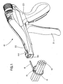
- Fig. 1 is a front upper right perspective view of a tool in accordance with an embodiment of the invention
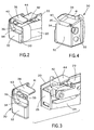
- Fig. 2 is an enlarged front upper right perspective view of the broken-away frontmost portion of the tool of Fig. 1 ;
- Fig. 3 is a view akin to that of Fig. 2 wherein a portion of the housing is removed and the blade guard is exploded to facilitate the viewing of interior parts;
- Fig. 4 is a rear lower right perspective view of the blade guard
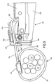
- Fig. 5 is a right side plan view of a front portion of the tool of Fig. 1 wherein a portion of the housing is removed to facilitate the viewing of interior parts and the tail portion of the cable tie has been inserted into the tool;
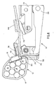
- Fig. 6 is a view akin to that of Fig. 5 wherein the tool has engaged the tie tail and tensioned the tie around the bundle of elongated objects;
- Fig. 7 is top plan view of a front portion of the tool of Fig. 1 ;
- Fig. 8 is an enlarged view of the front portion of the tool of Fig. 7 and the cable tie at the time the tail is being cut by the blade, taken in cross-section across the line 8-8 in Fig. 7 ;
- Fig. 9 is a further enlarged view of the front portion of the tool and the tie of Fig. 8 wherein the cable tie is being removed from the tool after severance and the tail has partially receded into the head, portions thereof being shown in section;
- Fig. 10 is a view of the cut cable tie after the tail has receded into the head of the tie, a portion thereof being shown in section;
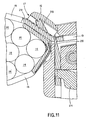
- Fig. 11 is a closeup view akin to Figs. 8 and 9 wherein an alternate in-line cable tie head is shown;
- Fig. 12 is a closeup view akin to Figs. 8 and 9 wherein a second alternate cable tie head is shown.
- the lesser snap-back of cable ties applied and severed at lower tensions means that a tie tail must be severed closer to the tie head to ensure that the potentially sharp severed edge of the tie tail recedes into the head so that it doesn't protrude and pose a danger to people or nearby objects.
- the claimed and described tool achieves a closer severance point by relieving the blade guard anvil and/or by increasing the recess depth of the blade guard (or decreasing the thickness of the spacer wall) so that the tie head can be pulled closer to the cut line of the blade before severance.
- cable ties having cooperatively configured heads may, especially in cooperation with the increased recess depth of the blade guard and/or relieved anvil, yields particularly desirable proximity between the severance point of the tie tail and the point the tail exits the cable tie head, so as to limit the required snap-back travel distance for the severed edge of the tail to recede into the head.
- the spacer portion of the blade guard assures a minimum snap-back distance before tie failure.
- the cable tie installation tool 10 shown generally in Fig. 1 , is used to tension a cable tie 12 around one or more objects, such as elongated objects 14, to bundle the objects together and/or facilitate mounting or routing the objects.
- a bundle of electrical wires or fiber optic cords may be bundled together to facilitate the handling and routing of the wires or cords.
- the cable tie 12 generally includes a head portion 16 having teeth 28 inset in a passageway 17 therethrough and a tail portion 18 having complementary teeth 29 thereon for interacting with the teeth 28 set in the head 16 to prevent the tail from excessively reversing through the passageway 17.
- the tool 10 may include a housing 20 ( Fig.
- Figs. 2-4 highlight a preferred embodiment of the inventive blade guard.
- the blade guard 30, disposed at the front of the tool 10 and adjoining the housing 20, has a front portion 32 having a recessed portion 34 thereon, and a side portion 33.
- the recessed portion 34 includes at its most recessed area a spacer portion 36.
- the blade guard 30 also includes an anvil portion 38, that preferably extends perpendicularly from the side portion 33, having a front edge 40 and a rear edge 41.
- the anvil portion 38 may serve to limit the forward travel of the tensioning assembly 22, such as when the pressure plate 44 contacts the rear edge 41 of the anvil portion 38.
- the anvil included a slot for receiving the cutting edge of a blade (not numbered, but observable in Fig. 15 of the '053 patent).
- the anvil portion 38 is preferably relieved from the front portion 32 to permit the cutting blade 26 to pass between them, i.e., behind the front portion 32, but in front of at least part of the anvil portion 38.
- the anvil may simply be made smaller so that the front edge 40 is relieved from the front portion 32 while the rear edge 41 is not displaced.
- Figs. 6-8 depict how the relieved anvil portion 38 and the recessed portion 34 permit the cable tie head portion 16 to be pulled by the tensioning mechanism 22 very near the cutting line of the blade 26.
- the blade may even preferably pass in front of the anvil portion 38 such that it makes contact or near-contact with the cable tie head portion 16 after passing through and severing the cut-away portion 19 from the remaining tail portion 18.
- Fig. 9 is an enlarged view wherein the cable tie is being withdrawn from the tool after severance and the tail is "snapping back" into the head under the low-tension force applied to the tail by the compressed bundle
- Fig. 10 is a view of the cut cable tie after the tail has receded into the head of the tie.
- Fig. 11 shows an embodiment of the invention wherein an alternate in-line cable tie head is depicted
- Fig. 12 shows a non in-line alternate cable tie head in use with an embodiment of the invention.
- a predetermined tension applied to a cable tie tale by a tensioning mechanism of the tool before severing of a cable tie tail.
- the limiting of the predetermined tension prevents undesirably high forces from being applied to cables or other objects within a cable tie loop.
- a predetermined tension of 18 pounds is the highest desirable tension.
- a predetermined tension of 10 pounds is the highest desirable tension.
- inventive blade guard would be applicable to many other tool designs and could achieve the same low-tension flush cut advantages with other tools. Additionally, it is anticipated that the inventive blade guard itself may assume different configurations.
- alternative embodiments might include blade guards having an anvil portion that may be a separate piece rather than integrally formed with the front and/or side portions. The scope of the invention is defined by the following claims.
Landscapes
- Engineering & Computer Science (AREA)
- Mechanical Engineering (AREA)
- Basic Packing Technique (AREA)
Claims (11)
- Outil d'installation d'attache de câble (10) pour tendre une attache de câble (12) autour d'une pluralité d'objets allongés (14) et couper une portion d'excédent de ladite attache de câble, ladite attache de câble comprenant une portion de tête (16) et une portion de queue (18), ledit outil comprenant:un boîtier (20) comportant une protection de lame (30) ayant une portion avant (32) et une portion d'enclume (38) ;un mécanisme de tension (22) supporté de manière opérationnelle par ledit boîtier pour tendre ladite attache de câble à un réglage de tension prédéterminé et retenir ladite portion de tête d'attache de câble au moins partiellement contre ladite protection de lame ; etun mécanisme de découpe (24) comprenant une lame se déplaçant en va-et-vient linéairement (26) pour découper ladite portion d'excédent de ladite attache de câble à proximité de ladite portion de tête une fois que ladite attache de câble a été placée au dit réglage de tension prédéterminé par ledit mécanisme de tension ;caractérisé en ce que ladite lame se déplaçant en va-et-vient linéairement passe derrière ladite portion avant de ladite protection de lame et devant ladite portion d'enclume de ladite protection de lame, un bord avant (40) de la portion d'enclume étant espacé de la portion avant de la protection de lame et d'une portion d'entretoise (36) de la protection de lame.
- Outil d'installation d'attache de câble (10) selon la revendication 1, dans lequel ledit outil peut être actionné manuellement.
- Outil d'installation d'attache de câble (10) selon la revendication 1, dans lequel ledit réglage de tension prédéterminé ne dépasse pas environ 8,16 kg (environ 18 livres).
- Outil d'installation d'attache de câble (10) selon la revendication 1, dans lequel ledit réglage de tension prédéterminé ne dépasse pas environ 4,54 kg (environ 10 livres).
- Outil d'installation d'attache de câble (10) selon la revendication 1,
dans lequel ladite portion avant de ladite protection de lame comprend une portion évidée (34) comportant une portion d'entretoise d'une épaisseur ne dépassant pas environ 0,076 cm (environ 0,030 pouce). - Outil d'installation d'attache de câble (10) selon la revendication 5, dans lequel ledit outil peut être actionné manuellement.
- Outil d'installation d'attache de câble (10) selon la revendication 5, dans lequel ledit réglage de tension prédéterminé ne dépasse pas environ 4,54 kg (environ 10 livres).
- Outil d'installation d'attache de câble (10) selon la revendication 5, dans lequel ledit réglage de tension prédéterminé ne dépasse pas environ 8,16 kg (environ 18 livres).
- Outil d'installation d'attache de câble (10) selon la revendication 1, dans lequel la portion d'enclume (38) comporte un bord arrière (41) pour limiter le déplacement vers l'avant du mécanisme de tension.
- Outil d'installation d'attache de câble (10) selon la revendication 1, dans lequel la portion avant (32) de la protection de lame (30) comprend une portion évidée (34).
- Outil d'installation d'attache de câble selon la revendication 10, dans lequel la portion d'enclume (38) et la portion évidée (34) de la protection de lame (30) permettent à la tête d'attache de câble d'être tirée par le mécanisme de tension à proximité de la lame (26).
Applications Claiming Priority (2)
| Application Number | Priority Date | Filing Date | Title |
|---|---|---|---|
| US57711804P | 2004-06-04 | 2004-06-04 | |
| PCT/US2005/019500 WO2005120956A2 (fr) | 2004-06-04 | 2005-06-02 | Outil d'installation d'attache de cable coupee a fleur |
Publications (2)
| Publication Number | Publication Date |
|---|---|
| EP1753660A2 EP1753660A2 (fr) | 2007-02-21 |
| EP1753660B1 true EP1753660B1 (fr) | 2012-12-19 |
Family
ID=34979569
Family Applications (1)
| Application Number | Title | Priority Date | Filing Date |
|---|---|---|---|
| EP05756269A Expired - Lifetime EP1753660B1 (fr) | 2004-06-04 | 2005-06-02 | Outil d'installation d'attache de cable coupee a fleur |
Country Status (4)
| Country | Link |
|---|---|
| US (2) | US7299830B2 (fr) |
| EP (1) | EP1753660B1 (fr) |
| MX (1) | MXPA06013843A (fr) |
| WO (1) | WO2005120956A2 (fr) |
Families Citing this family (28)
| Publication number | Priority date | Publication date | Assignee | Title |
|---|---|---|---|---|
| US7299830B2 (en) * | 2004-06-04 | 2007-11-27 | Panduit Corp. | Low tension flush cut-off cable tie installation tool |
| US8500739B2 (en) * | 2007-04-06 | 2013-08-06 | DePuy Synthes Products, LLC | Securing device to secure fixation devices to bone portions |
| US7591451B2 (en) * | 2007-11-13 | 2009-09-22 | Hellermanntyton Corporation | Bundle tie tensioning clutch |
| EP2408386B1 (fr) | 2009-03-19 | 2016-03-02 | Figure 8 Surgical, Inc. | Systèmes de réparation de sternum |
| US8460295B2 (en) | 2009-03-19 | 2013-06-11 | Figure 8 Surgical, Inc. | Systems and methods for sternum repair |
| US9398903B2 (en) | 2010-03-19 | 2016-07-26 | William T. MCCLELLAN | Knotless locking tissue fastening system and method |
| WO2012040449A1 (fr) * | 2010-09-22 | 2012-03-29 | Band-It-Idex, Inc. | Outil de groupage de câbles |
| US9113975B2 (en) * | 2011-06-17 | 2015-08-25 | Figure 8 Surgical, Inc | Sternum band tensioner device, system and method |
| US9394068B2 (en) | 2011-06-30 | 2016-07-19 | Hellermann Tyton Corporation | Cable tie tensioning and cut-off tool |
| USD692738S1 (en) | 2011-06-30 | 2013-11-05 | Hellermanntyton Corporation | Cable tie tensioning and cut-off tool |
| US9481102B1 (en) * | 2013-09-10 | 2016-11-01 | The Boeing Company | Spacer for a cable tie tensioning and severing tool |
| WO2015167920A1 (fr) | 2014-04-30 | 2015-11-05 | DePuy Synthes Products, Inc. | Instrument de mise en tension et systèmes de fixation d'os associés |
| US10138010B2 (en) * | 2014-05-21 | 2018-11-27 | Signode Industrial Group Llc | Tensioner/cutter tool for hose clamps and/or bands and attachments for tensioner/cutter |
| EP3514072B1 (fr) | 2014-12-12 | 2021-01-20 | Hellermanntyton Corporation | Mécanisme mixte de tension et d'étalonnage destiné à un outil de tension et de coupe d'attaches de câble |
| USD758155S1 (en) * | 2015-02-13 | 2016-06-07 | Panduit Corp. | Cable tie tool |
| JP1564309S (fr) * | 2016-04-06 | 2016-11-28 | ||
| JP2018057610A (ja) * | 2016-10-06 | 2018-04-12 | 敏定 齋藤 | 結束バンド用カッター |
| US10934044B2 (en) * | 2017-03-31 | 2021-03-02 | The Boeing Company | Tools for releasing cable ties |
| USD885861S1 (en) * | 2018-12-13 | 2020-06-02 | Hua Wei Industrial Co., Ltd. | Cable tie tool |
| TW202123889A (zh) | 2019-09-09 | 2021-07-01 | 美商潘瑟骨科股份有限公司 | 錨固件及張緊器與用於主動性骨骼與關節穩定裝置之錨固件負載系統 |
| US11511894B2 (en) | 2019-09-26 | 2022-11-29 | Hellermanntyton Corporation | Cable tie application tool |
| EP4347409A1 (fr) * | 2021-05-24 | 2024-04-10 | Illinois Tool Works, Inc. | Outil de serrage et de coupe d'un serre-câble |
| EP4163215A1 (fr) | 2021-10-01 | 2023-04-12 | HellermannTyton GmbH | Dispositif d'outil de fardelage automatique optimisé pour une plage d'épaisseurs de sangles d'une seule pièce |
| USD1012641S1 (en) * | 2021-10-25 | 2024-01-30 | Aptiv Technologies Limited | Tool nosepiece |
| US12157240B2 (en) * | 2021-10-26 | 2024-12-03 | Hellermanntyton Corporation | Severing a cable tie with a rounded cut |
| US12509260B2 (en) | 2022-01-11 | 2025-12-30 | Illinois Tool Works Inc. | Cable tie tool |
| DE202022002179U1 (de) | 2022-10-06 | 2024-01-11 | Hellermanntyton Gmbh | Automatische Bündelwerkzeugvorrichtung mit Führungseinheit für verformte und/oder lose einteilige Bänder |
| USD1051687S1 (en) * | 2023-01-25 | 2024-11-19 | Illinois Tool Works Inc. | Cable tie tool |
Family Cites Families (16)
| Publication number | Priority date | Publication date | Assignee | Title |
|---|---|---|---|---|
| US3712346A (en) * | 1971-03-26 | 1973-01-23 | Thomas & Betts Corp | Strap tightening and cutting tool |
| FR2416092A1 (fr) * | 1978-02-01 | 1979-08-31 | Usinage Tubes Pour Electr | Dispositif automatique pour la pose de colliers du type a cremaillere |
| US4321952A (en) * | 1980-01-21 | 1982-03-30 | American Casting & Mfg. Corporation | Strap tightening hand tool |
| JPS57204810A (en) * | 1981-05-29 | 1982-12-15 | Satoogoosee Kk | Bundling tool |
| US5065798A (en) * | 1991-01-28 | 1991-11-19 | Panduit Corp. | Stretched strap cable tie tensioning and severing tool |
| US5492156A (en) * | 1994-03-10 | 1996-02-20 | Tyton Corporation | Hand held tie tensioning and cut-off tool |
| ES2250824T3 (es) * | 1996-08-28 | 2006-04-16 | THOMAS & BETTS CORPORATION | Herramienta de instalacion de sujetacables. |
| US5921290A (en) * | 1997-04-08 | 1999-07-13 | Tyton Hellermann Corporation | Handheld tensioning and cutoff tool |
| US5832964A (en) * | 1997-10-24 | 1998-11-10 | Pandiut Corp. | Cable tie tensioning and severing tool |
| US7206646B2 (en) | 1999-02-22 | 2007-04-17 | Fisher-Rosemount Systems, Inc. | Method and apparatus for performing a function in a plant using process performance monitoring with process equipment monitoring and control |
| US6206053B1 (en) * | 1999-11-01 | 2001-03-27 | Panduit Corp. | Cable tie tensioning and severing tool |
| US7113085B2 (en) | 2000-11-07 | 2006-09-26 | Fisher-Rosemount Systems, Inc. | Enhanced device alarms in a process control system |
| JP3536045B2 (ja) * | 2002-01-21 | 2004-06-07 | タイトン株式会社 | 結束装置 |
| US6840289B2 (en) * | 2002-10-29 | 2005-01-11 | Panduit Corp. | Pneumatic cable tie tool |
| US7299830B2 (en) * | 2004-06-04 | 2007-11-27 | Panduit Corp. | Low tension flush cut-off cable tie installation tool |
| US7124787B2 (en) * | 2004-08-18 | 2006-10-24 | Hellermanntyton Corporation | Pneumatic cable tie installation tool |
-
2005
- 2005-06-02 US US11/143,073 patent/US7299830B2/en not_active Expired - Fee Related
- 2005-06-02 MX MXPA06013843A patent/MXPA06013843A/es active IP Right Grant
- 2005-06-02 WO PCT/US2005/019500 patent/WO2005120956A2/fr not_active Ceased
- 2005-06-02 EP EP05756269A patent/EP1753660B1/fr not_active Expired - Lifetime
-
2007
- 2007-10-23 US US11/876,908 patent/US7422037B2/en not_active Expired - Fee Related
Also Published As
| Publication number | Publication date |
|---|---|
| WO2005120956A2 (fr) | 2005-12-22 |
| US7422037B2 (en) | 2008-09-09 |
| MXPA06013843A (es) | 2007-02-02 |
| US7299830B2 (en) | 2007-11-27 |
| US20080035232A1 (en) | 2008-02-14 |
| EP1753660A2 (fr) | 2007-02-21 |
| US20050268983A1 (en) | 2005-12-08 |
| WO2005120956A3 (fr) | 2006-04-06 |
Similar Documents
| Publication | Publication Date | Title |
|---|---|---|
| US7422037B2 (en) | Low tension flush cut-off cable tie installation tool | |
| US7484993B2 (en) | Ethernet cable connector and methods of use thereof | |
| US8283564B2 (en) | Termination tool with corresponding male and female connectors | |
| US8739387B1 (en) | Reusable cable tie | |
| US4498507A (en) | Cable tie | |
| US6773311B2 (en) | Electrical splice connector | |
| EP1818275A1 (fr) | Serre-câble avec mecanismes de verrouillage fixés et articulés | |
| US9902519B2 (en) | Cutting tool and method of operating same | |
| US10329063B2 (en) | Cable tie strap and buckle | |
| CN112078963A (zh) | 用于棘爪闩锁装置的一体化释放结构 | |
| US9643764B1 (en) | Cable tie | |
| US8365418B2 (en) | Cable tie removal tool | |
| US6477746B1 (en) | Releasable ball-lock cable tie | |
| US20060096066A1 (en) | Side notched cable tie | |
| CN108134289B (zh) | 具有可移除外部负载条的电连接器及其使用方法 | |
| US7234669B2 (en) | Clamp | |
| RU2667588C2 (ru) | Стяжные устройства для обвязки кабелей и способы их использования | |
| JP2016188095A (ja) | 電線結束部材 | |
| JP6588802B2 (ja) | 光コネクタ及び光コネクタ製造方法 | |
| JP2006178289A (ja) | 光ファイバホルダおよび光ファイバケーブルの加工方法 | |
| KR200393276Y1 (ko) | 광케이블 메신저 와이어 클램프 | |
| CN2510420Y (zh) | 具有分离接头的扎线带 | |
| WO2007102828A1 (fr) | Attache de cable a encoches laterales | |
| HK1219352B (en) | Electrical connector with removable external load bar, and method of its use |
Legal Events
| Date | Code | Title | Description |
|---|---|---|---|
| PUAI | Public reference made under article 153(3) epc to a published international application that has entered the european phase |
Free format text: ORIGINAL CODE: 0009012 |
|
| 17P | Request for examination filed |
Effective date: 20061208 |
|
| AK | Designated contracting states |
Kind code of ref document: A2 Designated state(s): AT BE BG CH CY CZ DE DK EE ES FI FR GB GR HU IE IS IT LI LT LU MC NL PL PT RO SE SI SK TR |
|
| DAX | Request for extension of the european patent (deleted) | ||
| 17Q | First examination report despatched |
Effective date: 20100909 |
|
| GRAP | Despatch of communication of intention to grant a patent |
Free format text: ORIGINAL CODE: EPIDOSNIGR1 |
|
| GRAS | Grant fee paid |
Free format text: ORIGINAL CODE: EPIDOSNIGR3 |
|
| GRAA | (expected) grant |
Free format text: ORIGINAL CODE: 0009210 |
|
| AK | Designated contracting states |
Kind code of ref document: B1 Designated state(s): AT BE BG CH CY CZ DE DK EE ES FI FR GB GR HU IE IS IT LI LT LU MC NL PL PT RO SE SI SK TR |
|
| REG | Reference to a national code |
Ref country code: GB Ref legal event code: FG4D |
|
| REG | Reference to a national code |
Ref country code: CH Ref legal event code: EP |
|
| REG | Reference to a national code |
Ref country code: AT Ref legal event code: REF Ref document number: 589255 Country of ref document: AT Kind code of ref document: T Effective date: 20130115 |
|
| REG | Reference to a national code |
Ref country code: DE Ref legal event code: R096 Ref document number: 602005037501 Country of ref document: DE Effective date: 20130214 |
|
| PG25 | Lapsed in a contracting state [announced via postgrant information from national office to epo] |
Ref country code: SE Free format text: LAPSE BECAUSE OF FAILURE TO SUBMIT A TRANSLATION OF THE DESCRIPTION OR TO PAY THE FEE WITHIN THE PRESCRIBED TIME-LIMIT Effective date: 20121219 Ref country code: FI Free format text: LAPSE BECAUSE OF FAILURE TO SUBMIT A TRANSLATION OF THE DESCRIPTION OR TO PAY THE FEE WITHIN THE PRESCRIBED TIME-LIMIT Effective date: 20121219 Ref country code: ES Free format text: LAPSE BECAUSE OF FAILURE TO SUBMIT A TRANSLATION OF THE DESCRIPTION OR TO PAY THE FEE WITHIN THE PRESCRIBED TIME-LIMIT Effective date: 20130330 Ref country code: LT Free format text: LAPSE BECAUSE OF FAILURE TO SUBMIT A TRANSLATION OF THE DESCRIPTION OR TO PAY THE FEE WITHIN THE PRESCRIBED TIME-LIMIT Effective date: 20121219 |
|
| REG | Reference to a national code |
Ref country code: NL Ref legal event code: VDEP Effective date: 20121219 Ref country code: AT Ref legal event code: MK05 Ref document number: 589255 Country of ref document: AT Kind code of ref document: T Effective date: 20121219 |
|
| REG | Reference to a national code |
Ref country code: LT Ref legal event code: MG4D |
|
| PG25 | Lapsed in a contracting state [announced via postgrant information from national office to epo] |
Ref country code: GR Free format text: LAPSE BECAUSE OF FAILURE TO SUBMIT A TRANSLATION OF THE DESCRIPTION OR TO PAY THE FEE WITHIN THE PRESCRIBED TIME-LIMIT Effective date: 20130320 Ref country code: SI Free format text: LAPSE BECAUSE OF FAILURE TO SUBMIT A TRANSLATION OF THE DESCRIPTION OR TO PAY THE FEE WITHIN THE PRESCRIBED TIME-LIMIT Effective date: 20121219 |
|
| PG25 | Lapsed in a contracting state [announced via postgrant information from national office to epo] |
Ref country code: EE Free format text: LAPSE BECAUSE OF FAILURE TO SUBMIT A TRANSLATION OF THE DESCRIPTION OR TO PAY THE FEE WITHIN THE PRESCRIBED TIME-LIMIT Effective date: 20121219 Ref country code: IS Free format text: LAPSE BECAUSE OF FAILURE TO SUBMIT A TRANSLATION OF THE DESCRIPTION OR TO PAY THE FEE WITHIN THE PRESCRIBED TIME-LIMIT Effective date: 20130419 Ref country code: BE Free format text: LAPSE BECAUSE OF FAILURE TO SUBMIT A TRANSLATION OF THE DESCRIPTION OR TO PAY THE FEE WITHIN THE PRESCRIBED TIME-LIMIT Effective date: 20121219 Ref country code: BG Free format text: LAPSE BECAUSE OF FAILURE TO SUBMIT A TRANSLATION OF THE DESCRIPTION OR TO PAY THE FEE WITHIN THE PRESCRIBED TIME-LIMIT Effective date: 20130319 Ref country code: SK Free format text: LAPSE BECAUSE OF FAILURE TO SUBMIT A TRANSLATION OF THE DESCRIPTION OR TO PAY THE FEE WITHIN THE PRESCRIBED TIME-LIMIT Effective date: 20121219 Ref country code: AT Free format text: LAPSE BECAUSE OF FAILURE TO SUBMIT A TRANSLATION OF THE DESCRIPTION OR TO PAY THE FEE WITHIN THE PRESCRIBED TIME-LIMIT Effective date: 20121219 Ref country code: CZ Free format text: LAPSE BECAUSE OF FAILURE TO SUBMIT A TRANSLATION OF THE DESCRIPTION OR TO PAY THE FEE WITHIN THE PRESCRIBED TIME-LIMIT Effective date: 20121219 |
|
| PG25 | Lapsed in a contracting state [announced via postgrant information from national office to epo] |
Ref country code: NL Free format text: LAPSE BECAUSE OF FAILURE TO SUBMIT A TRANSLATION OF THE DESCRIPTION OR TO PAY THE FEE WITHIN THE PRESCRIBED TIME-LIMIT Effective date: 20121219 Ref country code: PL Free format text: LAPSE BECAUSE OF FAILURE TO SUBMIT A TRANSLATION OF THE DESCRIPTION OR TO PAY THE FEE WITHIN THE PRESCRIBED TIME-LIMIT Effective date: 20121219 Ref country code: PT Free format text: LAPSE BECAUSE OF FAILURE TO SUBMIT A TRANSLATION OF THE DESCRIPTION OR TO PAY THE FEE WITHIN THE PRESCRIBED TIME-LIMIT Effective date: 20130419 Ref country code: RO Free format text: LAPSE BECAUSE OF FAILURE TO SUBMIT A TRANSLATION OF THE DESCRIPTION OR TO PAY THE FEE WITHIN THE PRESCRIBED TIME-LIMIT Effective date: 20121219 |
|
| PLBE | No opposition filed within time limit |
Free format text: ORIGINAL CODE: 0009261 |
|
| STAA | Information on the status of an ep patent application or granted ep patent |
Free format text: STATUS: NO OPPOSITION FILED WITHIN TIME LIMIT |
|
| PG25 | Lapsed in a contracting state [announced via postgrant information from national office to epo] |
Ref country code: DK Free format text: LAPSE BECAUSE OF FAILURE TO SUBMIT A TRANSLATION OF THE DESCRIPTION OR TO PAY THE FEE WITHIN THE PRESCRIBED TIME-LIMIT Effective date: 20121219 |
|
| 26N | No opposition filed |
Effective date: 20130920 |
|
| PG25 | Lapsed in a contracting state [announced via postgrant information from national office to epo] |
Ref country code: CY Free format text: LAPSE BECAUSE OF FAILURE TO SUBMIT A TRANSLATION OF THE DESCRIPTION OR TO PAY THE FEE WITHIN THE PRESCRIBED TIME-LIMIT Effective date: 20121219 |
|
| PG25 | Lapsed in a contracting state [announced via postgrant information from national office to epo] |
Ref country code: IT Free format text: LAPSE BECAUSE OF FAILURE TO SUBMIT A TRANSLATION OF THE DESCRIPTION OR TO PAY THE FEE WITHIN THE PRESCRIBED TIME-LIMIT Effective date: 20121219 |
|
| REG | Reference to a national code |
Ref country code: DE Ref legal event code: R097 Ref document number: 602005037501 Country of ref document: DE Effective date: 20130920 |
|
| PG25 | Lapsed in a contracting state [announced via postgrant information from national office to epo] |
Ref country code: MC Free format text: LAPSE BECAUSE OF FAILURE TO SUBMIT A TRANSLATION OF THE DESCRIPTION OR TO PAY THE FEE WITHIN THE PRESCRIBED TIME-LIMIT Effective date: 20121219 |
|
| REG | Reference to a national code |
Ref country code: CH Ref legal event code: PL |
|
| REG | Reference to a national code |
Ref country code: IE Ref legal event code: MM4A |
|
| PG25 | Lapsed in a contracting state [announced via postgrant information from national office to epo] |
Ref country code: CH Free format text: LAPSE BECAUSE OF NON-PAYMENT OF DUE FEES Effective date: 20130630 Ref country code: LI Free format text: LAPSE BECAUSE OF NON-PAYMENT OF DUE FEES Effective date: 20130630 Ref country code: IE Free format text: LAPSE BECAUSE OF NON-PAYMENT OF DUE FEES Effective date: 20130602 |
|
| PG25 | Lapsed in a contracting state [announced via postgrant information from national office to epo] |
Ref country code: TR Free format text: LAPSE BECAUSE OF FAILURE TO SUBMIT A TRANSLATION OF THE DESCRIPTION OR TO PAY THE FEE WITHIN THE PRESCRIBED TIME-LIMIT Effective date: 20121219 |
|
| PG25 | Lapsed in a contracting state [announced via postgrant information from national office to epo] |
Ref country code: HU Free format text: LAPSE BECAUSE OF FAILURE TO SUBMIT A TRANSLATION OF THE DESCRIPTION OR TO PAY THE FEE WITHIN THE PRESCRIBED TIME-LIMIT; INVALID AB INITIO Effective date: 20050602 Ref country code: LU Free format text: LAPSE BECAUSE OF NON-PAYMENT OF DUE FEES Effective date: 20130602 |
|
| REG | Reference to a national code |
Ref country code: FR Ref legal event code: PLFP Year of fee payment: 12 |
|
| REG | Reference to a national code |
Ref country code: FR Ref legal event code: PLFP Year of fee payment: 13 |
|
| REG | Reference to a national code |
Ref country code: FR Ref legal event code: PLFP Year of fee payment: 14 |
|
| PGFP | Annual fee paid to national office [announced via postgrant information from national office to epo] |
Ref country code: FR Payment date: 20180626 Year of fee payment: 14 |
|
| PGFP | Annual fee paid to national office [announced via postgrant information from national office to epo] |
Ref country code: GB Payment date: 20180627 Year of fee payment: 14 Ref country code: DE Payment date: 20180627 Year of fee payment: 14 |
|
| REG | Reference to a national code |
Ref country code: DE Ref legal event code: R119 Ref document number: 602005037501 Country of ref document: DE |
|
| GBPC | Gb: european patent ceased through non-payment of renewal fee |
Effective date: 20190602 |
|
| PG25 | Lapsed in a contracting state [announced via postgrant information from national office to epo] |
Ref country code: DE Free format text: LAPSE BECAUSE OF NON-PAYMENT OF DUE FEES Effective date: 20200101 Ref country code: GB Free format text: LAPSE BECAUSE OF NON-PAYMENT OF DUE FEES Effective date: 20190602 |
|
| PG25 | Lapsed in a contracting state [announced via postgrant information from national office to epo] |
Ref country code: FR Free format text: LAPSE BECAUSE OF NON-PAYMENT OF DUE FEES Effective date: 20190630 |