EP1753650B1 - Verfahren zur bestimmung der mengencharakteristik eines sich bewegenden objekts und vorrichtung zur durchführung des verfahrens - Google Patents
Verfahren zur bestimmung der mengencharakteristik eines sich bewegenden objekts und vorrichtung zur durchführung des verfahrens Download PDFInfo
- Publication number
- EP1753650B1 EP1753650B1 EP05748315A EP05748315A EP1753650B1 EP 1753650 B1 EP1753650 B1 EP 1753650B1 EP 05748315 A EP05748315 A EP 05748315A EP 05748315 A EP05748315 A EP 05748315A EP 1753650 B1 EP1753650 B1 EP 1753650B1
- Authority
- EP
- European Patent Office
- Prior art keywords
- train
- laser
- determining
- outline
- measuring
- Prior art date
- Legal status (The legal status is an assumption and is not a legal conclusion. Google has not performed a legal analysis and makes no representation as to the accuracy of the status listed.)
- Expired - Lifetime
Links
Images


Classifications
-
- B—PERFORMING OPERATIONS; TRANSPORTING
- B61—RAILWAYS
- B61L—GUIDING RAILWAY TRAFFIC; ENSURING THE SAFETY OF RAILWAY TRAFFIC
- B61L23/00—Control, warning or like safety means along the route or between vehicles or trains
Definitions
- the present invention relates to a method for determining quantities characteristic of a moving object, and an apparatus for implementing the method.
- Both the method and the apparatus are of general use, even though a particular application relates to the railway sector.
- the constant increase in traffic and in the transit speed of trains together with ever increasing safety and quality standards demand constant and precise monitoring of a multiplicity of risk factors.
- the loads can undergo displacement from their original position and project beyond outline limits, risking collision with structures to the side of the track (poles, signals, cantilever roofs, tunnel walls).
- An aim of the invention is to propose a method for determining the characteristic quantities of a railway vehicle, and an apparatus for implementing the method, however it should be noted that the method and apparatus can be generally used to determine the characteristic quantities of any moving object.
- an apparatus is provided as described in claim 20.
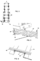
- the apparatus for implementing the method of the invention comprises an integral portal composed of two uprights 2 positioned on the two sides of a railway track 4 at any point of the track, for example before entering a particularly critical tunnel, or upstream of any portion of track to be monitored.
- a laser telemeter 6 positioned above the overall outline of the train 8, at least one traditional video camera 12 and a thermovisual video camera 10 for measuring the thermal profile of the train.
- a sensor 16 is positioned, which in cooperation with other similar sensors enables the static and dynamic load of the train 8 on the track 4 to be determined.
- photoelectric cell sensors 18 are provided for determining the passage and speed of the train 8.
- the laser telemeter 6 installed on each upright 2 comprises a laser source 20 able to transmit an amplitude modulated laser signal 22 of predetermined frequency, onto a rotary mirror rotating at a predetermined speed, such as to deviate the signal 22, consisting of a laser beam, into a vertical plane perpendicular to the travel direction of the train 8, with an angular swing able to scan the train.
- amplitude modulated laser signal means a pulse modulated laser signal (pulsed laser signal) or modulated with a known waveform not of pulse type (modulated laser signal).
- a sensor 26 is provided consisting of a photomultiplier tube able to receive the laser pulses reflected from the surface of the train 8, to reconstruct its outline.
- a special narrow band optical interference filter 28 is provided set for the laser wavelength, to immunize the system against any interference from external light and hence enable it to fully operate in any light condition.
- the tube is controlled by an electronic unit 30 (using a time to digital converter) able to calculate the distance between each of the points on the train 8 struck by the pulsed laser beam 22 and the sensor 26.
- the device for measuring the train thermal profile installed on each upright 2, comprises a pair of thermovisual video cameras 10, positioned at each of the two ends of the upright 2 and disposed with their optical axis converging in order to completely frame the transiting train 8. They are sensitive to the infrared waves emitted by the various parts of the train 8 and are able to reconstruct its thermal map. Specifically, that thermovisual video camera 10 positioned at the lower end of the upright 2 is orientated upwards, to determine the temperature of the brakes and of the train moving parts, while that thermovisual video camera 10 positioned at the upper end of the upright 2 is orientated downwards, to determine the temperature of the loads, of the external surfaces and of the pantograph trolley.
- the video cameras 10 are controlled by the local processing unit 30, which besides synchronizing their operation is able to collect data for local processing, in addition to memorizing the data and activating the connection to a remote computer 32.
- the thermovisual video cameras 10 are connected to the local processing unit 30 by optical fibres, which provide high immunity to noise.
- the device for measuring the static and dynamic load of the train is a high precision system for monitoring the stresses exerted by the train 8 on the track 4. Its principle of operation is based on determining the elastic deformations induced on each rail 42 on passage of the train 8, and more precisely on determining the deformations involving the elastic layer 44 present between each rail 42 and the underlying sleeper 14.
- This device consists essentially of a sound-configured sensor '16 mounted on a robust bracket and fixed to the sleeper 14 just below the foot of the rail 42. With this sensor there is associated a wire turn forming part of an LC circuit connected to an electronic control circuit 43.
- passage of the train causes temporary compression of the elastic layer 44 and a consequent increase in the distance between the sensor 16 and the upper surface of the foot of the rail 42.
- Measuring the resonance frequency of the LC circuit enables that distance to be calculated and hence the extent of the elastic stress due to passage of the train 8.
- each sleeper 14 For a more complete determination of the train characteristics, and more particularly of any faceting of the wheels 46 due to braking, sliding or load unbalance, several pairs of sensors 16 are provided, installed on each sleeper 14 in correspondence with both the rails 42 and for a number of sleepers corresponding to a length of track 4 at least equal to the circumference of the wheels 46 of the train 8.
- each sensor 16 is connected to the local processing unit 30 via fibre optic connections, which ensure a very high transmission speed for the relevant data.
- the device of the invention also comprises a unit for determining passage of the train 8 and for calculating its speed. Its purpose is to activate the aforedescribed devices only as the train 8 approaches, so that they operate only when necessary, to reduce their maintenance to a minimum.
- the photoelectric cell devices 18 for sensing passage of the train 8 and its speed, this latter being calculated from their distance apart and the time measured between passage of the train in front of them.
- Two traditional video cameras 12 sensitive to the visible spectrum are also installed on the two uprights between the sensing units and are synchronized with the other devices.
- the images acquired by these video cameras are used in particular situations to display to a remote operator the images of the train involved in the event to be indicated.
- the apparatus of the invention comprises a remote control unit to which measured data processed by the different local units are fed, in order to provide a complete picture of the characteristics of each train passing in front of the apparatus and to indicate any possible alarm situations due to differences between the measured parameters and the standard parameters beyond certain fixed thresholds.
- a pulsed laser beam 22 is directed onto the rotating mirror 24 to scan the train.
- Each laser pulse deviated by the rotating mirror 24 onto the surface of the train 8 is reflected thereby and sensed by the photomultiplier 26 positioned within the apparatus to the side of the laser source 20.
- each pulse there corresponds the determination of a point on the outline to be determined, so that on completion of scanning a certain number of points have been obtained which by subsequent interpolation enable the continuous outline of the investigated train to be defined.
- the measurement system is able to adapt to the train speed, because of the ability to vary the rotational speed of the mirror 24. This enables a finer threshold to be achieved for analyzing the outline in the case of goods trains (slower), which can more easily present projections beyond their outline. In such a case, which could for example create problems when the train 8 enters a tunnel, the system is able to feed a corresponding alarm signal and, if necessary, to cause the train to stop before it enters the track portion under control.
- thermovisual video cameras 10 are sensitive to the infrared radiation emitted by those parts of the train 8 framed by the video cameras.
- the intensity of the infrared radiation emitted by a unit of surface is related to the temperature of that unit, hence by measuring this radiation at various points the thermal map of the moving train can be constructed.
- the surface of the railway train is totally measured by using four video cameras 10, two for each side of the train 8, one of which is for the lower part (for analyzing overheating of brakes and moving parts) and the other for the upper part (for analyzing the loads, the outer surface and the pantograph trolley).
- the first processing step take place directly on board the video camera assembly, by the processing card connected to it.
- a control card synchronizes the various video cameras 10 and collects the data.
- Final processing of the acquired images is done by the local data processing unit 30, which also provides for memorization and activates the connection to the remote supervising computer 32.
- the processing system is able to analyze the thermal map determined by the video cameras 10. This analysis comprises verifying in continuous cycle the temperature at each point and comparing it with predetermined threshold values, to be able to immediately activate an alarm procedure should these values be exceeded.
- This alarm procedure comprises an automatic warning to the railway network and a simultaneous transmission to the central supervisory system of all information required to exactly identify the event which has caused the alarm, and in particular:
- the loads and stresses on the track 4 are calculated by measuring the elastic deformations induced in the track on passage of the train 8.
- the operating principle is based on the contactless inductive sensor 16 installed in proximity to the foot of the rail 42.
- a wire turn which, when current flows therethrough, generates on the forward lying rail foot a magnetic field which itself generates induced currents (Eddy currents) therein, which induce a magnetic counter-field in the original wire turn, of intensity related to the distance between the wire turn and the rail foot.
- This distance can be determined by an algorithm, by measuring the resonance frequency of the LC circuit comprising the wire turn.
- a pair of sensors 16 positioned on the same sleeper 14 in correspondence with the two rails 42 allows determination both of the weight supported by each train wheel axle and enables any load unbalance to be identified.
- the data obtained by the sensors 16 are transmitted through the optical fibre connection to the local processing system 30, which verifies by continuous cycle the loads measured by the sensor, stores them in its internal memory, compares them with the predetermined threshold and analyzes them to determine the unbalance or the dynamic stresses.
- the device for measuring the static and dynamic load of the train consists of a rigid bar 17, which supports three sensors of the same type as that already described.
- the rigid bar 17 is fixed at its ends to two adjacent sleepers and is able to sense and measure, by comparison between the three response signals of the three sensors on train passage, the deformations of the rails 42 caused thereby.
- each upright 2 there is applied a traditional video camera 12; these are synchronized with the other devices, their function being to acquire the image of that train part involved in the laser measurement, in order to display any abnormalities to the operator, who is distant from the measurement point.
- the acquisition system is integrated by reflectors operating only during acquisition and able to uniformly illuminate in a standard manner the image area taken.
- a pulsed laser beam at a frequency of 1 MHz was used for each sensor directed on the octagonal mirror 24, which was rotated at a speed of 3750 r.p.m., to hence obtain scanning by the beam over an angle of about 80° at a frequency of 30,000 scans per second.
- the profile measurement accuracy obtained was ⁇ 1 cm with a horizontal resolution of 5 cm and a vertical resolution at 200 km/h (passenger train) of 10 cm and a vertical resolution at 80 km/h (goods train) of 3 cm.
- the thermal profile of the train four video cameras were used able to acquire thermal images with a frequency of 20 Hz, i.e. 20 photographic images/second, with a resolution of 1 cm/pixel.
- the video cameras used by the measurement system were constructed using matrices of sensors based on Ga-As (gallium arsenide) technology which enable very high sensitivity, low noise and excellent thermal resolution to be obtained.
- This type of sensor is particularly rapid and hence has a very wide acquisition band (up to 20 GHz in the 8-12 ⁇ frequency spectrum.
- the standard matrix format of the pixels constituting the image plane of the sensor is 600x400. A measurement precision of ⁇ 2°C was obtained.
- the opening time for the shutter of the container housing each video camera is about 2 seconds.
- sensors were used having a measuring field of about 10 mm, with a maximum sensitivity to variations of about a few tens of microns.
- the minimum time required to obtain a measurement is about 10 ms, hence an acquisition frequency of about 100 Hertz can be obtained.
- a measurement precision of ⁇ 20 kg was obtained.
Landscapes
- Engineering & Computer Science (AREA)
- Mechanical Engineering (AREA)
- Train Traffic Observation, Control, And Security (AREA)
- Length Measuring Devices By Optical Means (AREA)
Claims (31)
- Verfahren zum Bestimmen der Mengencharakteristik eines beweglichen Objektes, insbesondere des Umrisses eines Eisenbahnzuges, gekennzeichnet durch:- Abtasten mit mindestens einem Lasertelemeter, dessen Lasersignal amplitudenmoduliert ist, durch Rotieren um eine Achse parallel zu der Bewegungsrichtung des Objektes,- Messen des Abstandes zwischen dem Telemeter und dem entsprechenden Punkt, der vom Laserstrahl getroffen wird, nach dem Etablieren eines Verhältnisses zwischen dem vom Laserstrahl im Moment der Messung angenommenen Abtastwinkel und dem Wert des entsprechenden gemessenen Abstands,- anschließendes Verarbeiten der bestimmten Daten, um somit die Punkte des Umrisses des Objekts zu bestimmen.
- Verfahren nach Anspruch 1, gekennzeichnet durch Abtasten mit einem gepulsten Lasersignal.
- Verfahren nach Anspruch 1, dadurch gekennzeichnet, dass nach dem Bestimmen der entsprechenden Punkte des vom dem Laserstrahl getroffenen Objekts durch die Messungen die übrigen Punkte durch Interpolation bestimmt werden, um den vollständigen Umriss des Objekts zu erhalten.
- Verfahren nach Anspruch 1, gekennzeichnet durch das Regulieren der Rotationsgeschwindigkeit des Lasertelemeterstrahls auf der Basis der Geschwindigkeit der Bewegung des Objekts.
- Verfahren nach Anspruch 1, gekennzeichnet durch die Verwendung von zwei Lasertelemetern, die auf beiden Seiten des beweglichen Objekts positioniert sind.
- Verfahren nach Anspruch 1, gekennzeichnet durch die Verwendung einer festen Laserquelle für jeden Telemeter, welche in Richtung eines rotierenden Spiegels ausgerichtet ist.
- Verfahren nach Anspruch 1, gekennzeichnet durch die Verwendung eines gepulsten Lasersignals bei einer Frequenz von ungefähr 1MHz.
- Verfahren nach Anspruch 1, gekennzeichnet durch Zwischenschalten eines optischen Schmalbandinterferenzfilters, der auf die Laserwellenlänge eingestellt ist, innerhalb des Weges des gepulsten Laserstrahls.
- Verfahren nach Anspruch 1 zum Bestimmen des Umrisses eines Eisenbahnzuges, dadurch gekennzeichnet, dass zusätzlich zum Bestimmen des Umrisses dieses Zuges seine Belastung später durch die Bestimmung elastischer Verformungen gemessen wird, welche bei der Durchfahrt des Zuges auf den Gleisen induziert werden.
- Verfahren nach Anspruch 9, gekennzeichnet durch Bestimmen der elastischen Verformungen durch Messen der Abweichungen in dem Abstand zwischen einem Sensor, der an der Gleisschwelle fixiert ist, und der Schiene, die auf einer elastischen auf der Schwelle liegenden Schicht liegt.
- Verfahren nach Anspruch 9, gekennzeichnet durch Bestimmen der elastischen Verformungen durch Messen der Abweichungen in dem Abstand zwischen mindestens drei Sensoren, die an einer festen Stange montiert sind, welche an ihren Enden an zwei Schwellen fixiert ist und leicht über der Schiene gehalten wird.
- Verfahren nach Anspruch 10 oder 11, gekennzeichnet durch Bestimmen der Abstandsabweichung zwischen der Schiene und dem Sensor durch Erzeugen eines Magnetfeldes auf einer Schiene mit einer LC-Schaltung, die in dem Sensor bereitgestellt ist, und anschließendem Messen der Abweichung in der Resonanzfrequenz der LC-Schaltung bei Durchfahrt des Zuges.
- Verfahren nach Anspruch 9, gekennzeichnet durch Ausführen der Belastungsmessung auf den beiden Schienen in Übereinstimmung mit derselben schrägen Fläche, um durch das Vergleichen der zwei Messungen ein Belastungsungleichgewicht zu bestimmen.
- Verfahren nach Anspruch 9, gekennzeichnet durch Ausführen der Belastungsmessungen auf einem Gleisabschnitt der Länge von mindestens der Umfangsfläche der Zugräder, und Vergleichen der Messwerte, um eine Radfläche zu bestimmen.
- Verfahren nach Anspruch 1 zum Bestimmen des Umrisses eines Eisenbahnzuges, dadurch gekennzeichnet, dass zusätzlich zum Bestimmen des Umrisses dieses Zuges das Wärmeprofil seiner verschiedenen Teile später unter Verwendung von mindestens einer befestigten Wärmebildkamera bestimmt wird, welche empfindlich auf die von den unterschiedlichen Teilen des Zuges ausgegebene Infrarotstrahlung reagiert.
- Verfahren nach Anspruch 15, gekennzeichnet durch die Verwendung einer unteren Videokamera auf jeder Seite des Zuges, die ausgerichtet ist, um die Temperatur der Bremsen und der beweglichen Teile zu messen, und einer oberen Videokamera, die ausgerichtet ist, um die Temperatur der Belastungen, der Außenflächen und des Stromabnehmerwagens des Zuges zu messen.
- Verfahren nach Anspruch 13, gekennzeichnet durch Vergleichen der von den Videokameras erhaltenen Temperaturdaten mit dem normalen Temperaturniveau der verschiedenen Teile des Eisenbahnzuges, und anschließendem Aktivieren eines Alarmsignals im Falle eines Unterschieds zwischen den Mess- und den Normalwerten.
- Verfahren nach Anspruch 1, gekennzeichnet durch Bestimmen des Bildes des Zugteils, der in die späteren Messungen eingebunden ist, mit mindestens einer Videokamera.
- Verfahren nach Anspruch 18, gekennzeichnet durch Illuminieren des von der Videokamera aufgenommenen Zugteiles während der Erfassung.
- Vorrichtung zum Implementieren des Verfahrens nach einem oder mehreren Ansprüchen von 1 bis 19, umfassend:- eine feste Struktur (2), die in der Nähe des Weges des Objektes positioniert ist, dessen Mengencharakteristiken zu bestimmen sind,- mindestens ein Lasertelemeter (6), das an der festen Struktur (2) befestigt ist und bei Durchfahrt des Objektes ein amplitudenmoduliertes Lasersignal aussenden kann,- Mittel (24) zum Rotieren des Lasertelemeters, so dass sich der ausgesendete Strahl dabei in die Ebene bewegt, die sich im Wesentlichen senkrecht zur Bewegungsrichtung des Objektes befindet,- Mittel (28) zum Messen des Abstandes zwischen dem Telemeter und dem Punkt, der von dem rotierenden Laserstrahl getroffen wird,- Mittel zum Korrelieren des vom Laserstrahl zum Zeitpunkt der Messung angenommenen Abtastwinkels mit dem von dem Messmittel bestimmten Abstandswert,- Mittel (30) zum Verarbeiten der bestimmten Messdaten und zum Bilden des Umrisses des Objektes durch Punkte.
- Vorrichtung nach Anspruch 20, dadurch gekennzeichnet, dass das Lasertelemeter eine Laserquelle (20) umfasst, die das Lasersignal auf einen rotierenden Spiegel (24) übertragen kann, der mit einer vorbestimmten Geschwindigkeit rotiert wird.
- Vorrichtung nach Anspruch 21, dadurch gekennzeichnet, dass verbunden mit der Laserquelle ein Sensor (26) bereitgestellt ist, der von dem Objekt reflektierte Laserimpulse empfangen kann, um den Umriss des Objektes zu rekonstruieren.
- Vorrichtung nach Anspruch 20, dadurch gekennzeichnet, dass die feste Struktur aus einem Portal besteht, dessen Ständer (2) auf beiden Seiten einer Gleisanlage (4) positioniert sind.
- Vorrichtung nach Anspruch 23, dadurch gekennzeichnet, dass an mindestens einem Ständer ein Gerät (10) angebracht ist, um das Wärmeprofil des auf der Gleisanlage fahrenden Zuges zu messen.
- Vorrichtung nach Anspruch 24, dadurch gekennzeichnet, dass das Messgerät ein Paar Wärmebildkameras umfasst, die so angeordnet sind, dass ihre optischen Achsen konvergieren, um den durchfahrenden Zug vollständig zu umrahmen.
- Vorrichtung nach Anspruch 20 und 25, dadurch gekennzeichnet, dass die Videokameras von dem Prozessormittel gesteuert werden.
- Vorrichtung nach Anspruch 20, dadurch gekennzeichnet, dass sie ein Gerät (16) zum Messen der statischen und dynamischen Belastung des Zuges umfasst.
- Vorrichtung nach Anspruch 27, dadurch gekennzeichnet, dass das Gerät aus einem Sensor besteht, der die Verformungen der elastischen Schicht (44) zwischen der Schiene (42) und der darunter befindlichen Schwelle (14) messen kann.
- Vorrichtung nach Anspruch 20, dadurch gekennzeichnet, dass sie eine Einheit zum Abtasten der Durchfahrt des Zuges und zur Berechnung seiner Geschwindigkeit umfasst.
- Vorrichtung nach Anspruch 23, dadurch gekennzeichnet, dass die herkömmlichen Videokameras (12), die empfindlich auf das sichtbare Spektrum reagieren, zwischen den Messeinheiten auf den Ständern installiert und mit den anderen Geräten synchronisiert sind.
- Vorrichtung nach Anspruch 27, dadurch gekennzeichnet, dass das Gerät zum Messen der statischen und dynamischen Belastung eine feste Stange (17) ist, die mindestens drei Sensoren unterstützt.
Applications Claiming Priority (2)
| Application Number | Priority Date | Filing Date | Title |
|---|---|---|---|
| ITVE20040026 ITVE20040026A1 (it) | 2004-06-11 | 2004-06-11 | Metodo di rilevamento di grandezze caratteristiche di un oggetto in movimento ed apparecchiatura per attuare il metodo. |
| PCT/EP2005/006191 WO2005120923A1 (en) | 2004-06-11 | 2005-06-09 | Method for determining quantities characteristic of a moving object and apparatus for implementing the method |
Publications (2)
| Publication Number | Publication Date |
|---|---|
| EP1753650A1 EP1753650A1 (de) | 2007-02-21 |
| EP1753650B1 true EP1753650B1 (de) | 2007-11-28 |
Family
ID=34971902
Family Applications (1)
| Application Number | Title | Priority Date | Filing Date |
|---|---|---|---|
| EP05748315A Expired - Lifetime EP1753650B1 (de) | 2004-06-11 | 2005-06-09 | Verfahren zur bestimmung der mengencharakteristik eines sich bewegenden objekts und vorrichtung zur durchführung des verfahrens |
Country Status (4)
| Country | Link |
|---|---|
| EP (1) | EP1753650B1 (de) |
| DE (1) | DE602005003571T2 (de) |
| IT (1) | ITVE20040026A1 (de) |
| WO (1) | WO2005120923A1 (de) |
Cited By (3)
| Publication number | Priority date | Publication date | Assignee | Title |
|---|---|---|---|---|
| RU2430848C1 (ru) * | 2010-03-25 | 2011-10-10 | Открытое Акционерное Общество "Российские Железные Дороги" | Устройство для дистанционного контроля состояния буксы колесной пары |
| CN102470884A (zh) * | 2009-07-16 | 2012-05-23 | 西门子公司 | 带有传感器装置的有轨车辆 |
| EA019944B1 (ru) * | 2011-12-12 | 2014-07-30 | Открытое Акционерное Общество Научно-Производственное Предприятие "Альфа-Прибор" | Автоматизированная система коммерческого осмотра "смотровая вышка" |
Families Citing this family (3)
| Publication number | Priority date | Publication date | Assignee | Title |
|---|---|---|---|---|
| WO2010012022A1 (en) * | 2008-07-31 | 2010-02-04 | Bill Hartmann | System for weighing an axle of a wagon |
| US9956972B2 (en) * | 2015-03-02 | 2018-05-01 | Siemens Industry, Inc. | Detection of dynamic train-to-rail shunting performance |
| DE102021100505A1 (de) | 2021-01-13 | 2022-07-14 | Deutsche Bahn Aktiengesellschaft | Überwachungsverfahren |
Family Cites Families (5)
| Publication number | Priority date | Publication date | Assignee | Title |
|---|---|---|---|---|
| JPH04326744A (ja) * | 1991-04-26 | 1992-11-16 | Hitachi Electron Eng Co Ltd | 異物検査装置 |
| CA2102140C (en) * | 1993-11-01 | 1999-02-02 | Grigory Izbinsky | Wayside monitoring of the angle-of-attack of railway vehicle wheelsets |
| JP2000127972A (ja) * | 1998-10-27 | 2000-05-09 | Mitsubishi Heavy Ind Ltd | プラットホーム安全設備 |
| DE20020009U1 (de) * | 2000-11-24 | 2001-03-01 | Ludwig, Peter, 90513 Zirndorf | Überwachungssystem zur Abfertigungskontrolle eines Zuges, insbesondere bei einer U- oder S-Bahn, mit ergänzbarer Überwachung auch des Gleisbettraumes |
| DE20106818U1 (de) * | 2001-04-20 | 2002-06-06 | Honeywell Ag, 63067 Offenbach | Vorrichtung zur Überwachung eines Bahnsteiggleisbereichs an Haltestellen |
-
2004
- 2004-06-11 IT ITVE20040026 patent/ITVE20040026A1/it unknown
-
2005
- 2005-06-09 DE DE602005003571T patent/DE602005003571T2/de not_active Expired - Lifetime
- 2005-06-09 EP EP05748315A patent/EP1753650B1/de not_active Expired - Lifetime
- 2005-06-09 WO PCT/EP2005/006191 patent/WO2005120923A1/en not_active Ceased
Cited By (4)
| Publication number | Priority date | Publication date | Assignee | Title |
|---|---|---|---|---|
| CN102470884A (zh) * | 2009-07-16 | 2012-05-23 | 西门子公司 | 带有传感器装置的有轨车辆 |
| CN102470884B (zh) * | 2009-07-16 | 2015-07-22 | 西门子公司 | 带有传感器装置的有轨车辆 |
| RU2430848C1 (ru) * | 2010-03-25 | 2011-10-10 | Открытое Акционерное Общество "Российские Железные Дороги" | Устройство для дистанционного контроля состояния буксы колесной пары |
| EA019944B1 (ru) * | 2011-12-12 | 2014-07-30 | Открытое Акционерное Общество Научно-Производственное Предприятие "Альфа-Прибор" | Автоматизированная система коммерческого осмотра "смотровая вышка" |
Also Published As
| Publication number | Publication date |
|---|---|
| EP1753650A1 (de) | 2007-02-21 |
| ITVE20040026A1 (it) | 2004-09-11 |
| DE602005003571T2 (de) | 2008-10-23 |
| DE602005003571D1 (de) | 2008-01-10 |
| WO2005120923A1 (en) | 2005-12-22 |
Similar Documents
| Publication | Publication Date | Title |
|---|---|---|
| CA3049267C (en) | Broken wheel detection system | |
| EP0751371B1 (de) | Installation und Verfahren zum Messen von Rollparametern durch künstliches Sehen bei Eisenbahnfahrzeugrädern | |
| US4259018A (en) | Optical track gage measuring device | |
| CN104364607B (zh) | 轨道车辆的车轮相对于轨道的几何形状的轨旁测量 | |
| US5368260A (en) | Wayside monitoring of the angle-of-attack of railway vehicle wheelsets | |
| US7507965B2 (en) | Smart thermal imaging and inspection device for wheels and components thereof and method | |
| CN112172862A (zh) | 一种多功能轨道检测系统 | |
| CN107688024A (zh) | 一种基于单目视觉与激光散斑的铁轨扣件异常检测系统 | |
| CN104050811B (zh) | 激光机动车分型系统及方法 | |
| US5446291A (en) | Method for classifying vehicles passing a predetermined waypoint | |
| DK158079B (da) | Anlaeg til sporbaseret aftastning af hjulprofilen paa forbikoerende jernbanehjul | |
| CN107703149A (zh) | 一种基于双目视觉与激光散斑的铁轨扣件异常检测系统 | |
| CN112762994A (zh) | 走行部状态监测装置和方法 | |
| RU2720603C1 (ru) | Интегрированный пост автоматизированного приема и диагностики подвижного состава (призма) | |
| EP1753650B1 (de) | Verfahren zur bestimmung der mengencharakteristik eines sich bewegenden objekts und vorrichtung zur durchführung des verfahrens | |
| CN207248770U (zh) | 一种基于双目视觉与激光散斑的铁轨扣件异常检测装置 | |
| CN106428108A (zh) | 列车装载安全检测装置 | |
| CN209553217U (zh) | 一种基于激光和图像结合的铁路限界检测系统 | |
| JP3474230B2 (ja) | レール締結装置の緩み検出装置 | |
| CN207248769U (zh) | 一种基于单目视觉与激光散斑的铁轨扣件异常检测装置 | |
| JP3339719B2 (ja) | トロリー線の高さ測定装置 | |
| CN114126947A (zh) | 用于检测线路基础设施,尤其是铁路线路的位置和几何结构的系统、车辆及方法 | |
| CN117781868A (zh) | 列车轮对尺寸检测与动态图像检测融合的检测系统及方法 | |
| EP0727039B1 (de) | Bahnseitige messvorrichtung fur die winkellage eines zugwagenradsatzes | |
| KR20010027668A (ko) | 광섬유 센서를 통한 차량감지및 교통정보 수집원리 |
Legal Events
| Date | Code | Title | Description |
|---|---|---|---|
| PUAI | Public reference made under article 153(3) epc to a published international application that has entered the european phase |
Free format text: ORIGINAL CODE: 0009012 |
|
| AK | Designated contracting states |
Kind code of ref document: A1 Designated state(s): AT BE BG CH CY CZ DE DK EE ES FI FR GB GR HU IE IS IT LI LT LU MC NL PL PT RO SE SI SK TR |
|
| 17P | Request for examination filed |
Effective date: 20070210 |
|
| GRAP | Despatch of communication of intention to grant a patent |
Free format text: ORIGINAL CODE: EPIDOSNIGR1 |
|
| DAX | Request for extension of the european patent (deleted) | ||
| GRAS | Grant fee paid |
Free format text: ORIGINAL CODE: EPIDOSNIGR3 |
|
| GRAA | (expected) grant |
Free format text: ORIGINAL CODE: 0009210 |
|
| AK | Designated contracting states |
Kind code of ref document: B1 Designated state(s): AT BE BG CH CY CZ DE DK EE ES FI FR GB GR HU IE IS IT LI LT LU MC NL PL PT RO SE SI SK TR |
|
| REG | Reference to a national code |
Ref country code: GB Ref legal event code: FG4D |
|
| REG | Reference to a national code |
Ref country code: IE Ref legal event code: FG4D |
|
| REG | Reference to a national code |
Ref country code: CH Ref legal event code: EP |
|
| REF | Corresponds to: |
Ref document number: 602005003571 Country of ref document: DE Date of ref document: 20080110 Kind code of ref document: P |
|
| REG | Reference to a national code |
Ref country code: CH Ref legal event code: NV Representative=s name: ABREMA AGENCE BREVET ET MARQUES, GANGUILLET |
|
| PG25 | Lapsed in a contracting state [announced via postgrant information from national office to epo] |
Ref country code: SE Free format text: LAPSE BECAUSE OF FAILURE TO SUBMIT A TRANSLATION OF THE DESCRIPTION OR TO PAY THE FEE WITHIN THE PRESCRIBED TIME-LIMIT Effective date: 20080228 Ref country code: NL Free format text: LAPSE BECAUSE OF FAILURE TO SUBMIT A TRANSLATION OF THE DESCRIPTION OR TO PAY THE FEE WITHIN THE PRESCRIBED TIME-LIMIT Effective date: 20071128 Ref country code: ES Free format text: LAPSE BECAUSE OF FAILURE TO SUBMIT A TRANSLATION OF THE DESCRIPTION OR TO PAY THE FEE WITHIN THE PRESCRIBED TIME-LIMIT Effective date: 20080311 |
|
| NLV1 | Nl: lapsed or annulled due to failure to fulfill the requirements of art. 29p and 29m of the patents act | ||
| PG25 | Lapsed in a contracting state [announced via postgrant information from national office to epo] |
Ref country code: IS Free format text: LAPSE BECAUSE OF FAILURE TO SUBMIT A TRANSLATION OF THE DESCRIPTION OR TO PAY THE FEE WITHIN THE PRESCRIBED TIME-LIMIT Effective date: 20080328 Ref country code: FI Free format text: LAPSE BECAUSE OF FAILURE TO SUBMIT A TRANSLATION OF THE DESCRIPTION OR TO PAY THE FEE WITHIN THE PRESCRIBED TIME-LIMIT Effective date: 20071128 Ref country code: BG Free format text: LAPSE BECAUSE OF FAILURE TO SUBMIT A TRANSLATION OF THE DESCRIPTION OR TO PAY THE FEE WITHIN THE PRESCRIBED TIME-LIMIT Effective date: 20080228 Ref country code: LT Free format text: LAPSE BECAUSE OF FAILURE TO SUBMIT A TRANSLATION OF THE DESCRIPTION OR TO PAY THE FEE WITHIN THE PRESCRIBED TIME-LIMIT Effective date: 20071128 Ref country code: PL Free format text: LAPSE BECAUSE OF FAILURE TO SUBMIT A TRANSLATION OF THE DESCRIPTION OR TO PAY THE FEE WITHIN THE PRESCRIBED TIME-LIMIT Effective date: 20071128 Ref country code: SI Free format text: LAPSE BECAUSE OF FAILURE TO SUBMIT A TRANSLATION OF THE DESCRIPTION OR TO PAY THE FEE WITHIN THE PRESCRIBED TIME-LIMIT Effective date: 20071128 |
|
| PG25 | Lapsed in a contracting state [announced via postgrant information from national office to epo] |
Ref country code: AT Free format text: LAPSE BECAUSE OF FAILURE TO SUBMIT A TRANSLATION OF THE DESCRIPTION OR TO PAY THE FEE WITHIN THE PRESCRIBED TIME-LIMIT Effective date: 20071128 |
|
| PG25 | Lapsed in a contracting state [announced via postgrant information from national office to epo] |
Ref country code: DK Free format text: LAPSE BECAUSE OF FAILURE TO SUBMIT A TRANSLATION OF THE DESCRIPTION OR TO PAY THE FEE WITHIN THE PRESCRIBED TIME-LIMIT Effective date: 20071128 Ref country code: CZ Free format text: LAPSE BECAUSE OF FAILURE TO SUBMIT A TRANSLATION OF THE DESCRIPTION OR TO PAY THE FEE WITHIN THE PRESCRIBED TIME-LIMIT Effective date: 20071128 |
|
| ET | Fr: translation filed | ||
| PG25 | Lapsed in a contracting state [announced via postgrant information from national office to epo] |
Ref country code: BE Free format text: LAPSE BECAUSE OF FAILURE TO SUBMIT A TRANSLATION OF THE DESCRIPTION OR TO PAY THE FEE WITHIN THE PRESCRIBED TIME-LIMIT Effective date: 20071128 Ref country code: SK Free format text: LAPSE BECAUSE OF FAILURE TO SUBMIT A TRANSLATION OF THE DESCRIPTION OR TO PAY THE FEE WITHIN THE PRESCRIBED TIME-LIMIT Effective date: 20071128 Ref country code: RO Free format text: LAPSE BECAUSE OF FAILURE TO SUBMIT A TRANSLATION OF THE DESCRIPTION OR TO PAY THE FEE WITHIN THE PRESCRIBED TIME-LIMIT Effective date: 20071128 |
|
| PG25 | Lapsed in a contracting state [announced via postgrant information from national office to epo] |
Ref country code: PT Free format text: LAPSE BECAUSE OF FAILURE TO SUBMIT A TRANSLATION OF THE DESCRIPTION OR TO PAY THE FEE WITHIN THE PRESCRIBED TIME-LIMIT Effective date: 20080428 |
|
| PLBE | No opposition filed within time limit |
Free format text: ORIGINAL CODE: 0009261 |
|
| STAA | Information on the status of an ep patent application or granted ep patent |
Free format text: STATUS: NO OPPOSITION FILED WITHIN TIME LIMIT |
|
| 26N | No opposition filed |
Effective date: 20080829 |
|
| PG25 | Lapsed in a contracting state [announced via postgrant information from national office to epo] |
Ref country code: MC Free format text: LAPSE BECAUSE OF NON-PAYMENT OF DUE FEES Effective date: 20080630 Ref country code: GR Free format text: LAPSE BECAUSE OF FAILURE TO SUBMIT A TRANSLATION OF THE DESCRIPTION OR TO PAY THE FEE WITHIN THE PRESCRIBED TIME-LIMIT Effective date: 20080229 |
|
| PG25 | Lapsed in a contracting state [announced via postgrant information from national office to epo] |
Ref country code: IE Free format text: LAPSE BECAUSE OF NON-PAYMENT OF DUE FEES Effective date: 20080609 Ref country code: EE Free format text: LAPSE BECAUSE OF FAILURE TO SUBMIT A TRANSLATION OF THE DESCRIPTION OR TO PAY THE FEE WITHIN THE PRESCRIBED TIME-LIMIT Effective date: 20071128 |
|
| PG25 | Lapsed in a contracting state [announced via postgrant information from national office to epo] |
Ref country code: CY Free format text: LAPSE BECAUSE OF FAILURE TO SUBMIT A TRANSLATION OF THE DESCRIPTION OR TO PAY THE FEE WITHIN THE PRESCRIBED TIME-LIMIT Effective date: 20071128 |
|
| GBPC | Gb: european patent ceased through non-payment of renewal fee |
Effective date: 20090609 |
|
| PG25 | Lapsed in a contracting state [announced via postgrant information from national office to epo] |
Ref country code: GB Free format text: LAPSE BECAUSE OF NON-PAYMENT OF DUE FEES Effective date: 20090609 |
|
| PG25 | Lapsed in a contracting state [announced via postgrant information from national office to epo] |
Ref country code: LU Free format text: LAPSE BECAUSE OF NON-PAYMENT OF DUE FEES Effective date: 20080609 Ref country code: HU Free format text: LAPSE BECAUSE OF FAILURE TO SUBMIT A TRANSLATION OF THE DESCRIPTION OR TO PAY THE FEE WITHIN THE PRESCRIBED TIME-LIMIT Effective date: 20080529 |
|
| PG25 | Lapsed in a contracting state [announced via postgrant information from national office to epo] |
Ref country code: TR Free format text: LAPSE BECAUSE OF FAILURE TO SUBMIT A TRANSLATION OF THE DESCRIPTION OR TO PAY THE FEE WITHIN THE PRESCRIBED TIME-LIMIT Effective date: 20071128 |
|
| REG | Reference to a national code |
Ref country code: FR Ref legal event code: PLFP Year of fee payment: 12 |
|
| REG | Reference to a national code |
Ref country code: FR Ref legal event code: PLFP Year of fee payment: 13 |
|
| REG | Reference to a national code |
Ref country code: FR Ref legal event code: PLFP Year of fee payment: 14 |
|
| REG | Reference to a national code |
Ref country code: CH Ref legal event code: NV Representative=s name: ABREMA AGENCE BREVETS ET MARQUES, GANGUILLET, CH Ref country code: CH Ref legal event code: PFUS Owner name: MER MEC SPA, IT Free format text: FORMER OWNER: TECNOGAMMA S.P.A., IT |
|
| REG | Reference to a national code |
Ref country code: DE Ref legal event code: R082 Ref document number: 602005003571 Country of ref document: DE Representative=s name: POTTHAST & SPENGLER PATENTANWAELTE PARTNERSCHA, DE Ref country code: DE Ref legal event code: R081 Ref document number: 602005003571 Country of ref document: DE Owner name: MER MEC SPA, IT Free format text: FORMER OWNER: TECNOGAMMA S.P.A., BADOERE DI MORGANO, IT |
|
| REG | Reference to a national code |
Ref country code: CH Ref legal event code: PFUS Owner name: MER MEC SPA, IT Free format text: FORMER OWNER: MER MEC SPA, IT |
|
| PGFP | Annual fee paid to national office [announced via postgrant information from national office to epo] |
Ref country code: DE Payment date: 20210629 Year of fee payment: 17 Ref country code: FR Payment date: 20210618 Year of fee payment: 17 Ref country code: IT Payment date: 20210618 Year of fee payment: 17 |
|
| PGFP | Annual fee paid to national office [announced via postgrant information from national office to epo] |
Ref country code: CH Payment date: 20210702 Year of fee payment: 17 |
|
| REG | Reference to a national code |
Ref country code: DE Ref legal event code: R119 Ref document number: 602005003571 Country of ref document: DE |
|
| REG | Reference to a national code |
Ref country code: CH Ref legal event code: PL |
|
| PG25 | Lapsed in a contracting state [announced via postgrant information from national office to epo] |
Ref country code: LI Free format text: LAPSE BECAUSE OF NON-PAYMENT OF DUE FEES Effective date: 20220630 Ref country code: FR Free format text: LAPSE BECAUSE OF NON-PAYMENT OF DUE FEES Effective date: 20220630 Ref country code: CH Free format text: LAPSE BECAUSE OF NON-PAYMENT OF DUE FEES Effective date: 20220630 |
|
| PG25 | Lapsed in a contracting state [announced via postgrant information from national office to epo] |
Ref country code: DE Free format text: LAPSE BECAUSE OF NON-PAYMENT OF DUE FEES Effective date: 20230103 |
|
| PG25 | Lapsed in a contracting state [announced via postgrant information from national office to epo] |
Ref country code: IT Free format text: LAPSE BECAUSE OF NON-PAYMENT OF DUE FEES Effective date: 20220609 |