EP1753522B1 - Vorrichtung und verfahren zur osmotischen membrandestillation - Google Patents
Vorrichtung und verfahren zur osmotischen membrandestillation Download PDFInfo
- Publication number
- EP1753522B1 EP1753522B1 EP05742602.5A EP05742602A EP1753522B1 EP 1753522 B1 EP1753522 B1 EP 1753522B1 EP 05742602 A EP05742602 A EP 05742602A EP 1753522 B1 EP1753522 B1 EP 1753522B1
- Authority
- EP
- European Patent Office
- Prior art keywords
- solution
- alkali metal
- chamber
- metal halide
- spent
- Prior art date
- Legal status (The legal status is an assumption and is not a legal conclusion. Google has not performed a legal analysis and makes no representation as to the accuracy of the status listed.)
- Expired - Lifetime
Links
Images

Classifications
-
- B—PERFORMING OPERATIONS; TRANSPORTING
- B01—PHYSICAL OR CHEMICAL PROCESSES OR APPARATUS IN GENERAL
- B01D—SEPARATION
- B01D61/00—Processes of separation using semi-permeable membranes, e.g. dialysis, osmosis or ultrafiltration; Apparatus, accessories or auxiliary operations specially adapted therefor
- B01D61/36—Pervaporation; Membrane distillation; Liquid permeation
- B01D61/364—Membrane distillation
-
- C—CHEMISTRY; METALLURGY
- C01—INORGANIC CHEMISTRY
- C01B—NON-METALLIC ELEMENTS; COMPOUNDS THEREOF; METALLOIDS OR COMPOUNDS THEREOF NOT COVERED BY SUBCLASS C01C
- C01B17/00—Sulfur; Compounds thereof
- C01B17/69—Sulfur trioxide; Sulfuric acid
- C01B17/88—Concentration of sulfuric acid
-
- C—CHEMISTRY; METALLURGY
- C25—ELECTROLYTIC OR ELECTROPHORETIC PROCESSES; APPARATUS THEREFOR
- C25B—ELECTROLYTIC OR ELECTROPHORETIC PROCESSES FOR THE PRODUCTION OF COMPOUNDS OR NON-METALS; APPARATUS THEREFOR
- C25B15/00—Operating or servicing cells
- C25B15/08—Supplying or removing reactants or electrolytes; Regeneration of electrolytes
-
- C—CHEMISTRY; METALLURGY
- C25—ELECTROLYTIC OR ELECTROPHORETIC PROCESSES; APPARATUS THEREFOR
- C25B—ELECTROLYTIC OR ELECTROPHORETIC PROCESSES FOR THE PRODUCTION OF COMPOUNDS OR NON-METALS; APPARATUS THEREFOR
- C25B15/00—Operating or servicing cells
- C25B15/08—Supplying or removing reactants or electrolytes; Regeneration of electrolytes
- C25B15/087—Recycling of electrolyte to electrochemical cell
Definitions
- This invention relates to apparatus and method for the recovery and concentration of heavy chemical liquors using osmotic membrane distillation, particularly spent alkali metal halide solutions from electrolytic cells and more particularly, spent sodium chloride solutions from the production of sodium hydroxide and chlorine gas.
- a nearly saturated NaCl brine solution is fed to an electrolyzer, where upon application of DC current, chlorine gas is evolved at the anode while water is electrochemically reduced to gaseous hydrogen and hydroxyl ions at the cathode.
- Anode and cathode are typically separated by a microporous diaphragm or perfluorinated cation exchange membrane such as those known under the trademarks, Nafion ® , Flemion ® or Aciplex ® .
- Some chloralkali plants may still utilize the older mercury-based process, in which there is no separator between the electrodes and the cathode reaction is formation of Na-amalgam.
- Raw NaCl brine is typically prepared from solid NaCl and water in a brine saturator. It then undergoes one or two stages of purification to remove the hardness metals, such as Ca and Mg, as well as other metallic and non-metallic impurities. Both chemical precipitation methods and ion exchange methods are commonly used to purify the NaCl brine for membrane cell plants.
- the brine preparation and processing stages are commonly referred to as the Brine Treatment section of the chloralkali plant and can account for up to 10-15% of the total plant cost.
- chloralkali brine preparation and purification is given, for example, in a chapter on Chlorine in Industrial Inorganic Chemicals and Products -An Ullmann's Encyclopedia, vol.2, Wiley-VCH, Weinheim, 1999, pp. 1123-1255 .
- a typical concentration of the feed brine is 305 + 10 g/L and in the course of membrane cell electrolysis, the NaCl concentration gets depleted by approximately a third, i.e. to 190 ⁇ 10 g/L.
- Brine, after electrolysis, is called Spent Brine, Weak Brine or Return Brine.
- Spent Brine is first de-chlorinated and then, typically, returned to a brine saturator, as one of several make-up components to prepare the raw feed brine. It should be appreciated that Spent Brine is very pure, i.e. "super-pure", when in the membrane plant and its recycle to the brine saturator is solely for the purpose of getting it re-concentrated back to the original strength, i.e. the 305 ⁇ 10 g/L.
- Osmotic Membrane Distillation is based on molecular diffusion, or, in the case of smaller membrane pores, a mixed molecular and Knudsen diffusion. In either case, the rate of transfer is proportional to the water vapor difference across the membrane, membrane porosity and the reciprocals of membrane thickness and tortuosity.
- Suitable membrane materials include, for example, microporous fluoropolymers PTFE, FEP, PFA, PVDF, and the like, polyolefins, such as, PP, PE, and polysulfones and the like.
- microporous inorganic materials including carbon and glass
- they have been made hydrophobic by either (i) mixing with any of the above polymers or (ii) surface treatment, e.g. with organic silicones.
- a thin non-porous membrane film made of polymer characterized by high free volume which makes it permeable to gases and water vapor.
- polymers are poly (1-trimethylsilyl-1-propyne) (PTMSP) or 2,2-bistrifluoromethyl-4,5-difluoro-1,3-dioxole/tetrafluoroethylene copolymer (Teflon AF ® 2400) as a water vapor permeable membrane.
- PTMSP poly (1-trimethylsilyl-1-propyne)
- Teflon AF ® 2400 2,2-bistrifluoromethyl-4,5-difluoro-1,3-dioxole/tetrafluoroethylene copolymer
- the receiver solution or "water sink” is, typically, a concentrated solution of CaCl 2 , MgCl 2 , NaCl, potassium hydrogen phosphate(s) or pyrophosphate(s).
- OMD osmotic membrane distillation
- U.S. Patent 4,781,837 granted November 1, 1988 to Lefebvre, Michel S.M. , discloses an OMD process for concentration of fruit or vegetable juices, milk, whey, by contacting such, across a hydrophobic, microporous barrier with a highly concentrated receiver solution of salt, such as NaCl or MgSO 4 .
- USP 4,781,837 also discloses a process whereby the spent receiver solution per se is re-concentrated, e.g. by Reverse Osmosis (RO) and re-cycled back to the OMD stage.
- the cited process temperature is 40°C.
- USP 4,781,837 also discloses a concept of extracting potable water from seawater, by a combination ofOMD and RO.
- U.S. Patent 5,098,566, granted March 24, 1992 to Lefebvre, Michel S.M. discloses a hydrophobic microporous membrane with optimized thickness and porosity, particularly useful for the OMD process.
- USP 5,098,566 explicitly teaches the differentiation between Membrane Distillation (MD) and OMD, with the former technique not being isothermal and always conducted under a significant a temperature gradient, i.e. 50°C or so across the hydrophobic microporous membrane.
- U.S. Patent 5,382,365, granted January 17, 1995 to Deblay is somewhat similar and exemplifies cases of OMD-enabled concentration of liquid pharmaceutical intermediates or grape juice as well as solid food products (sliced apples).
- the preferable dehydrating agent (Receiver) is a concentrated solution of CaCl 2 . Regeneration and re-cycling of the Receiver solution is specifically described.
- U.S. Patent 5,938,928, granted August 17, 1999 Michaels A.N. discloses an OMD process for the concentration of juices and beverages, which utilizes a laminate membrane consisting of a hydrophobic microporous layer linen with a thin non-porous hydrophilic film. Such laminate structure was shown to be effective in preventing wetting of the OMD membrane.
- US5965004 discloses a method whereby chlorine dioxide is generated by electrochemical oxidation of sodium chlorite in an anode compartment of a cation exchange membrane, divided cell. This takes place via a membrane distillation process for which a temperature gradient over the membrane between 0.1 and 100°C is fotseen. There is no disclosure of use of a concentrated receive solution.
- heavy chemical in this specification is also restricted to the production of inorganic chemicals when manufactured in a heavy chemical process plant.
- the invention provides a method of enhancing the concentration of a first inorganic compound in a first aqueous solution, said first inorganic compound is an alkali metal halide and said first aqueous solution is an alkali metal halide solution of a first process of a chemical plant, comprising an electrolytic cell said method comprising
- the invention provides a second process of said heavy chemical plant; and further collecting said diluted receiver feed aqueous solution.
- the resultant first solution and diluted receiver feed solution are recycled back to the heavy chemical plant.
- the first solution is subject to the OMD step at a practical temperature selected from at least 50°C to up to its boiling point.
- the temperature is selected to provide a practical vapor pressure differential with the receiver solution.
- the invention provides as hereinabove defined is wherein said first compound is an alkali metal halide, and said alkali metal halide solution is spent solution from an electrolytic cell for the electrolytic production of halogen and alkali metal hydroxide from said alkali metal halide.
- the preferred method according to the invention described herein takes advantage of a common situation in a chemical plant, especially chloralkali or sodium chlorate plant, where there are multiple process streams, which normally require addition of de-mineralized water and, hence, are potential Receivers (water sinks) for water vapor removed from Spent Brine.
- Such streams arc described below as follows.
- the water vapor partial pressure over Spent Brine (16-17% w/w NaCI) is 0.02 bar at room temperature and 0.42 bar at 80°C, respectively.
- the method according to the invention employs Osmotic Membrane Distillation (OMD) wherein a process stream to be concentrated is contacted across a hydrophobic, preferably, microporous membrane, with a more concentrated stream, referred to herein as Receiver Stream or Receiver.
- OMD Osmotic Membrane Distillation
- Receiver is characterized by having a lower water vapor pressure that the Process Stream. As long as the difference in water vapor pressure over the two streams is maintained, there will be a net water vapor transport to the Receiver.
- the OMD process is considered to be isothermal.
- the invention provides a method of enhancing the concentration of alkali metal halide in an aqueous solution comprising
- the hydrophobic membrane is microporous.
- the invention provides an improved electrolytic process for the production of alkali metal hydroxide and halogen gas from an alkali metal halide solution, said process comprising electrolyzing said aqueous solution of said alkali metal halide in an electrolytic cell to produce said alkali metal hydroxide, gaseous halogen, and spent alkali metal halide solution, the improvement compromising subjecting at least a portion of said spent alkali metal halide solution having a spent vapor pressure to an osmotic membrane distillation means comprising a hydrophobic gas and water vapor permeable membrane separating (i) a spent solution chamber for receiving said spent solution, from (ii) a receiver chamber for receiving an aqueous receiver feed solution having a receiver solution vapor pressure lower than said spent vapor pressure; and feeding and said at least portion of said spent alkali metal halide solution to said spent solution chamber; feeding said receiver feed solution to said receiver chamber as to effect transfer of water vapor through said membrane from said spent solution chamber to said
- OMD contactors exemplifying the osmotic membrane distillation means
- other types of membrane contactors are available and can be adapted for the OMD process.
- the Membrana Division of Celgard Corp. fabricates a contactor called Liqui-CelTM, which employs polypropylene (PP) fibres (0.3 mm OD 0.03 ⁇ m mean pore size) woven into loose fabric, which is then inserted into a shell.
- PP polypropylene
- One stream flows through the lumens of the PP hollow fibres, while the other stream flows generally on the shell side.
- This particular contactor uses a central feeding of the shell-side stream and a central baffle to ensure that at least part of the shell -side stream flows in the direction normal to the fibre.
- Liqui- CelTM contactors were developed for gasifying/de-gasifying of liquid solutions or solvent extraction applications.
- Another example of a commercially available membrane contactor is a pHasorTM unit available from Mykrolis Corporation.
- This shell-and-tube contactor contains microporous PFA membrane capillaries and is primarily used for bubble-free gas transfer into fluids, especially transfer of ozone into semiconductor process streams.
- Yet another device adaptable as an OMD contactor is the Microza® unit, available commercially from Pall Corp. This unit is also of the shell-and-tubc type and it incorporates a bundle of microporous PVDF capillaries as the membrane. The intended Microza® unit use is for a crossflow microfiltration.
- membrane contactors may employ hollow-fiber, tubular i.e. capillary or flat membranes made of polymers mentioned hereinabove, in either microporous of non-porous form.
- the contactor configuration may be plate-and-frame type, spiral-wound or pleated - for flat type membranes.
- the shell-and-tube or transverse flow, whcrin the Process Steam and the Receiver flow normally to each other, module cypes are more appropriate.
- some membrane contactor fabricators have weaved or bonded individual hollow fibers, or capillaries, as mats or fabrics. They can then be handled in a similar fashion as flat membranes and packaged into, e.g a spiral-wound module.
- the membrane serves as a non-wettable barrier between the treated solution, e.g. Spent Brine and the Receiver, which transfers water vapor and other volatile components and conducts heat.
- the invention provides apparatus for enhancing the concentration of a first inorganic compound in a first aqueous solution having a first water vapor pressure provided by a first process of a heavy chemical plant by osmotic membrane distillation, said apparatus comprising Osmotic membrane distillation means comprising
- the invention provides apparatus for concentrating an alkali metal halide solution by osmotic membrane distillation comprising
- the invention provides an improved halo alkali production plant comprising an electrolytic cell for the electrolytic production of alkali metal hydroxide and halogen from an alkali metal halide solution; means for feeding feed alkali metal halide solution to said cell; means for collecting spent alkali metal halide solution from said cell having spent water vapour pressure from said cell; means for collecting said alkali metal hydroxide from said cell;
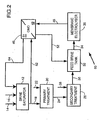
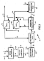
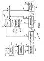
- Figs.(1) - (4 ) are schematic diagrams of chloralkali production plants incorporating Spent Brine re-concentration membrane contactor units, according to the invention; and wherein the same numerals denote like parts.
- Fig. 1 shows a simplified diagram of a brine treatment train, electrolyzer and a catholyte re-circulation loop, generally as 10, wherein product sodium hydroxide catholyte solution is passed to the OMD unit as a Receiver "water sink", herein the second chamber of the OMD means.
- Raw feed brine is prepared in a brine saturator 12, to which solid NaCl salt 14 and process water 16 are added. Saturated brine 18 is then passed to a primary brine treatment stage 20, where, upon the addition of treatment chemicals, NaOH and Na 2 CO 3 , denoted as 22, most of any hardness impurities are precipitated and the solids clarified and/or filtered out, to yield purified feed brine 24.
- the purified feed brine needs to undergo further purification or "polishing" in a secondary brine treatment 26, which utilizes chelating ion exchange resin IX to selectively remove trace multivalent cationic impurities from the brine.
- the IX resin is re-generated with HCl and NaOH, jointly denoted as regeneration chemicals 28.
- the "polished brine” 30 is pumped to feed brine tank 32 and then, upon demand, as stream 34, to the electrolysis section, designated as the membrane electrolyzer 36.
- Electrolyzer 36 is coupled with catholyte re-circulation tank 38, which feeds about 28-30% w/w NaOH to electrolyzer 36 as stream 40.
- the catholyte NaOH concentration increases to 32-33% w/w. Normally, part of this, as caustic stream 42 is collected as product caustic 44, while the balance is returned to 38. Similarly the Spent Brine stream would normally be returned back to brine saturator 12.
- the OMD contactor unit stage 46 is introduced to contact Spent Brine 48 in first chamber 49 of the OMD means, and the above mentioned balance of caustic product 50, in second chamber 51 to effect the osmotic transfer of water vapor from 48 to 50.
- the NaCl concentration of the Spent Brine in chamber 49 increases.
- This re-concentrated brine 52 can now be fed directly to feed brine tank 32 and bypass the conventional path through the aforesaid saturator and two brine treatment stages.
- the NaOH concentration in chamber 51 and of caustic catholyte 50 decreases, as forming stream 54, which is returned to the catholyte re-circulation tank 38.
- Fig. 2 shows, generally as 60, a configuration in which the Receiver is a concentrated raw NaCl brine 62, "water sink” split from stream 18, from the brine saturator 12. Following the osmotic pick-up of water, this brine gets diluted and is returned as stream 64 back to saturator 12. It follows that the input of process water stream 16, will be reduced in comparison with that required in the absence of the OMD stage. It should be appreciated that with this configuration, due to the higher partial water vapor pressure over saturated brine, the driving force for the OMD stage will be reduced, when compared with the process seen in Fig. 1 , hereinabove.
- Fig. 3 shows, generally as 70, a chloralkali plant which produces liquid sodium hypochlorite bleach, wherein sodium hydroxide and product are the Receiver "water sink".
- a 32-33% w/w NaOH product is first diluted to about 20% w/w strength and then reacted with gaseous Cl 2 to make the NaOCl.
- This is a favorable case, since it poses the greatest de-mineralized water requirement for both caustic dilution in the catholyte loop, and the above mentioned product caustic dilution, before it is fed to the hypochlorite reactor.
- the increased de-mineralized water requirement translates to a larger water sink for the water to be extracted from the Spent Brine.
- Fig. 3 shows two OMD stages. A part of the catholyte caustic product stream 42 is split-off as product caustic 72, which undergoes "deep" dilution in one OMD-2 stage 74, while the balance of caustic is moderately diluted in OMD-1 stage 46 and then returned to the catholyte re-circulation tank as stream 54. Spent Brine 48 flows first through OMD-1 and is concentrated to an intermediate level in stream 52.
- Fig. 4 depicts, generally as 80, the embodiment of Fig. 1 , except it now explicitly shows a Spent Brine de-chlorination stage 82.
- De-chlorinating chemicals HCl, NaOH and Na 2 SO 3 are shown as streams 84, 86 and 88, respectively.
- Receivers and combination of Receivers can be used to extract water from Spent Brine by the OMD method.
- spent acid from the chlorine drying stage can advantageously be employed, either alone or in combination with other Receivers.
- the most effective Receivers are those characterized by the lowest water vapor partial pressure at a given temperature. Further, it is advantageous to operate at higher temperatures, since this tends to increase the effective water vapor partial pressure difference between Spent Brine and the Receiver.
- the upper OMD operating temperature limit is defined by the materials of construction in the OMD module, particularly the membranes and potting material.
- the design of the module is important for achieving high rates of water vapor transfer per available membrane area.
- concentration polarization on the Spent Brine and Receiver sides will contribute to decreasing the effective water vapor pressure driving force for the process.
- the contacted streams should be re-circulated rapidly through the OMD modules. Means to increase the turbulence of the solutions at the OMD membrane are preferred.
- a transverse flow OMD module design in which at least one of the contacting streams flows normally to the membrane e.g. in a membrane hollow-fiber, is believed to be a more efficient OMD contactor when compared with a conventional shell-and-tube type using co- or counter-current flows.
- Module OD 48 mm
- Capillary/PVDF Membrane OD/ID: 2.3/1.4 mm # of capillaries 140
- Membrane area 0.12 m 2 (based on ID)
- Spent brine (18% w/w NaCl) was pumped on the shell side of Microza® unit at 2.7 ml/min (linear velocity: ⁇ 0.5 cm/sec), while 30.5% w/w NaOH Receiver solution was pumped through the lumen side of the PVDF capillaries at 2.5 ml/min (linear velocity in each capillary ⁇ 1.2 cm/sec).
- Spent brine and Receiver temperatures were varied but kept equal to each other. In the process the Spent brine became concentrated to the 25-26% w/w level.
- the estimated initial differential water vapor pressure difference (driving force) was 0.080 bar at 30°C and 0.080 bar at 60°C, respectively.
- the measured water transfer rates were as follows: Temperature, °C H 2 O transfer rate, kg/m 2 hr 22 0.42 35 0.80 45 1.00 55 1.25 65 11.5
- Example 2 Conditions were similar to that in Example 1 except that the temperature was fixed to 73°C and the lumen side flow was increased to 7.6 ml/sec ( ⁇ 3.5 cm/sec), while the shell side flow (Spent brine) was varied.
- the measured water transfer rates were as follows: Shell side flow, ml/sec H 2 O transfer rate, kg/m 2 hr 6.6 2.25 8.5 2.90 10.0 3.30
- Gore-Tex® tubular PTFE® membranes were used in a membrane contactor of the undisclosed flow-type configuration for OMD process. Some description of the membrane module and membranes are given in Table 1. Table 1. Gore-Tex tubular membranes and a membrane module used in the experiments. Membrane form/material Tubes/PTFE Active area of the membrane module based on the tube-side 1.1 m 2 Active tube length 43.1 cm Porosity of membranes ⁇ 50% Membrane tube ID ⁇ 0.55 mm Membrane tube OD ⁇ 0.80 mm Membrane tube thickness ⁇ 0.125 mm
- Spent brine (17.5 wt.% NaCl) was pumped on the shell side of the membrane contactor comprising Gore-Tex tubular membranes at a linear velocity of ⁇ 7.4 cm/sec.
- Receiver solution comprising 30% NaOH was pumped through the tube-side of the PTFE tubular membranes at a linear velocity of ⁇ 21 cm/sec per each tube.
- Spent brine and Receiver temperatures were varied but kept equal to each other (see a table further below): Temperature, °C H 2 O transfer rate, kg/m 2 hr 50 1.24 60 3.82 70 5.56
- the estimated initial water vapour pressure difference ranged between ⁇ 0.048 and 0.122 Bar.
- the estimated initial water vapour pressure difference ranged between ⁇ 0.130 and 0.145 Bar.
- the estimated initial water vapour pressure difference (driving force) ranged between ⁇ 0.109 and 0.151 Bar.
- Some description of the membrane capillaries and a membrane bundle are given in Table 2.
- Membrane form/material Capillaries/HALAR® Active area of the membrane bundle 0.15 m 2 Active capillary length 17.5 cm Membrane ID 0.39 mm Membrane OD 0.65 mm Membrane tube thickness 0.13 mm Nominal Pore Size 0.1 ⁇ m
- the estimated initial water vapour pressure difference (driving force) was ⁇ 0.102 Bar.
- Example 3 e.g., tubular Gore-Tex PTFE membranes
- DI water was fed in the shell side of the membrane contactor at 6.7 cm/sec at various temperatures.
- Receiver Solution was fed into the lumen of the tubes at ⁇ 28 cm/sec per tube at the same temperatures as water feed.
- Initial concentration of the Receiver Solution slightly varied but was approximately 30% wt and measured each time before an experiment.
- the following table presents water transfer rates obtained at various water vapour pressure differences (see table further below): H 2 O vapour pressure differences, Bar H 2 O transfer rate, kg/m 2 hr 0.104 4.0 0.130 4.9 0.151 6.0
- the present invention provides apparatus and processes for the re-concentration of a spent aqueous solution of a chemical process stream of a heavy chemical plant in an efficacious and efficient manner, optionally at not hithertobefore relatively high temperatures and harsh conditions.
- the water transformed by the OMD process is used, concomitantly, as desired dilution water for another process stream which forms part of the full chemical plant.
- Such action reduces or eliminates the need for and cost of fresh demineralized or like "make-up” water, or a "dedicated” Receiver and reconditioning of the Receiver.
- the rate of re-concentration can be enhanced by operations at relatively high temperatures not acceptable in prior art commercial operations owing to the temperature sensitivity of the chemical compounds.
- Such high temperatures enhance water vapor pressure differences between the solutions to maximize the OMD rates.
- Such high temperature operations allow for the utilization of the "already hot" process streams in the OMD step, such that essentially no net heat is either generated or consumed, and, thus, the costs of cooling and/or heating steps are either eliminated or reduced. This is particularly so where there is no ready available source of energy e.g. high or low pressure steam.
Landscapes
- Chemical & Material Sciences (AREA)
- Organic Chemistry (AREA)
- Engineering & Computer Science (AREA)
- Water Supply & Treatment (AREA)
- Chemical Kinetics & Catalysis (AREA)
- Electrochemistry (AREA)
- Inorganic Chemistry (AREA)
- Materials Engineering (AREA)
- Metallurgy (AREA)
- Life Sciences & Earth Sciences (AREA)
- Sustainable Development (AREA)
- Separation Using Semi-Permeable Membranes (AREA)
- Electrolytic Production Of Non-Metals, Compounds, Apparatuses Therefor (AREA)
Claims (21)
- Ein Methode zur Verbesserung der Konzentration einer ersten anorganischen Verbindung (14) in einer ersten wässerigen Lösung (48), wobei die erste anorganische Verbindung ein Alkali-metallhalogenid ist und besagte erste wässerige Lösung eine Alkalimetall-Halogenidlösung eines ersten Prozesses einer chemischen Anlage ist, die eine elektrolytische Zelle (36) umfasst und besagte Methode aus folgendem besteht:a) Einspeisung von besagter ersten Lösung (48), die besagte erste Verbindung in einer ersten Konzentration aufweist und einen ersten Wasserdampfdruck in ein Destillationsgerät (46), das eine hydrophobische, gas- und wasserdampfdurchlässige Membrane umfasst, eine (i) erste Kammer (49) zur Aufnahme besagter ersten Lösung (48) aus einer zweiten (ii) Kammer (51) zur Aufnahme einer wässerigen Vorlagenbeschickungslösung (50), die einen zweiten Wasserdampfdruck niedriger als den besagte erste Wasserdampfdruck aufweist;b) Einspeisung von besagter wässerigen Vorlagenbeschickungslösung (50) in besagte zweite Kammer (51), um Durchgang von Wasserdampf durch besagte Membrane aus der besagten ersten Kammer (49) in besagte zweite Kammer (51) zu bewirken und eine (i) daraus resultierende erste Lösung (52) herzustellen, die eine zweite Konzentration besagter erster Verbindung (14) aufweist, die stärker als die erste Konzentration ist und eine (ii) verdünnte wässerige Vorlagenbeschickungs-lösung (54);c) Auffangen besagter resultierender ersten Lösung (52),
dadurch gekennzeichnet, dass besagtes Destillationsgerät (46) ein osmotisches Membrandes-tillationsgerät ist und wo die besagte wässerige Vorlagenbeschickungslösung (50) eine Produkt-lösung einer elektrolytischen Zelle (36) für die elektrolytische Herstellung eines Alkalimetallhydroxids ist, das vom besagten Alkalimetallhalogenid abgeleitet wurde, und wo besagte Methode weiterhin folgenden Schritt enthält:d) Rückführung von wenigstens einer Portion der besagten ersten Lösung (52) innerhalb besagter chemischen Anlage zur besagten elektrolytischen Zelle (36). - Eine Methode wie in Anspruch 1 definiert, wo besagte verdünnte, wässerigere Vorlagen-beschickungslösung innerhalb besagter chemischen Anlage an besagte elektrolytische Zelle rückge-führt wird.
- Eine Methode wie in Anspruch 1 oder 2 definiert, wo besagte erste Lösung eine Temperatur aufweist, die aus einem Bereich selektiert wird, der sich wenigstens von 50 °C bis unter ihren Siedepunkt beläuft.
- Eine Methode wie in einem der Ansprüche 1 bis 3 definiert, wo besagte wässerige Vorlagen-beschickurlgslösung eine Temperatur aufweist, die aus einem Bereich von wenigstens 50 °C bis 80°C selektiert wird.
- Eine Methode wie in einem der Ansprüche 1 bis 4 definiert, wo besagte Membrane mikroporös ist.
- Eine Methode wie in Anspruch 5 definiert, wo besagte Membrane eine Porengröße von <0.5µm aufweist.
- Eine Methode wie in einem der Ansprüche 1 bis 6 definiert, wo besagte hydrophobische Membrane durch großes freies Volumen gekennzeichnet wird und porenfrei ist.
- Eine Methode wie in einem der Ansprüche 1 bis 7 definiert, wo besagte Alkalimetall-Halogenidlösung eine erschöpfte Lösung von einer elektrolytischen Zelle für die elektrolytische Herstellung von Halogen und Alkalimetallhydroxid aus besagtem Alkalimetallhalogenid ist.
- Eine Methode wie in Anspruch 8 definiert, wo besagtes Alkalimetallhalogenid Natriumchlorid ist.
- Eine Methode wie in Anspruch 1 definiert, wo besagte wässerige Vorlagenbeschickungslösung aus Natriumhydroxid einer Katolytrezirkulierungsschleife selektiert wird und das Produkt Natriumhy-droxid zur Herstellung von Natriumhydroxidbleiche geeignet ist.
- Eine Methode wie in einem der Ansprüche 8 bis 10 definiert, wo besagte resultierende Alkalimetall-Halogenidlösung Lake ist, die eine zweite Konzentration von wenigstens 22% Gewichtsprozent aufweist.
- Eine Methode wie in einem der Ansprüche 8 bis 11 definiert, wo besagte Alkalimetall-Halogenidlösung Natriumchlorid und Chlor umfasst und weiter Entchlorung besagter Lösung umfasst, die gleichzeitig in besagtem osmotischen Membrandestillationsgerät auftritt.
- Eine Methode wie in einem der Ansprüche 1 bis 12 definiert, wo besagtes osmotisches Membrandestillationsgerät eine Mehrheit von besagten osmotischen Membrandestillations-geräteeinheiten umfasst, die parallel und/oder reihenweise verbunden sind.
- Eine Methode wie in einem der Ansprüche 1 bis 13 definiert, wo besagte Lösung in besagter ersten Kammer und/oder zweiten Kammer einem Rührvorgang unterzogen wird, der aus Gruppe, die aus Air-Sparging, Turbulenzpromotoren und pulsierendem Durchfluss besteht, selektiert wird.
- Eine Methode wie in einem der Ansprüche 1 bis 14 definiert, wo besagtes osmotisches Membrandestillationsgerät eine Einheit umfasst, die aus der Gruppe, die aus einem Platte-Rahmen-System, Rohrbündelgerät und Falten- oder Querstromkonstruktion-Membrankontaktorgerät besteht, selektiert wird.
- Ein Methode wie in einem der Ansprüche 1 definiert, wo die erste anorganische Verbindung ein Alkalimetallhalogenid ist und die erste wässerige Lösung eine Alkalimetall-Halogenidlösung ist, besagter Prozess Elektrolyse besagter wässerigen Alkalimetall-Halogenidlösung in einer elektrolytischen Zelle (36) eines Elektrolysegeräts umfasst, um Alkalimetallhydroxid, gasförmiges Halogen und erschöpfte Alkalimetall-Halogenidlösung herzustellen, wo wenigstens ein Teil der besagten erschöpften Alkalimetall-Halogenidlösung, die einen Wasserdampfdruck aufweist, der osmotischen Membrandestillationsmethode unterworfen wird, die die hydrophobische, gas- und wasserdurchlässige Membrane umfasst, (i) die die erste Kammer (49) für erschöpfte Lösung zur Aufnahme besagter erschöpfter Lösung zur Aufnahme aus der (ii) zweiten Vorlagekammer (51) zur Aufnahme der wässerigen Vorlagebeschickungslösurig trennt, die einen niedrigeren Vorlagelösungs-Wasserdampfdruck als der erschöpfte Wasserdampfdruck hat und wenigstens ein Teil der besagten erschöpften Alkalimetall-Halogenidlösung in die Kammer für erschöpfte Lösung eingespeist wird, besagte Vorlagenbeschickungslösung in besagte Vorlagenkammer eingespeist wird, um Transfer von Wasserdampf durch die besagte Membrane aus der Kammer für erschöpfte Lösung (49) an die besagte Vorlagenkammer (51) zu bewirken, um eine resultierende konzentriertere Alkalimetall-Halogenidlösung herzustellen und eine resultierende weniger konzentrierte Vorlagenbeschickungslösung, und wenigstens einen Teil der besagen resultierenden ersten Lösung in der besagten chemischen Anlage an besagte elektrolytische Zelle rückzuführen.
- Eine Methode wie in Anspruch 16 definiert, wo besagte wässerige Vorlagenbeschickungslösung eine Lösung umfasst, die aus einer Gruppe, die aus (i) konzentrierter Lake, (ii) konzentriertem Alkali-metallhydroxid und (iii) erschöpfter Schwefelsäure von einem Chlortrocknungsprozess besteht, selektiert wird.
- Eine Methode wie in Anspruch 16 oder 17 definiert, wo resultierende konzentriertere Alkali-metall-Halogenidlösung an besagte elektrolytische Zelle rückgeführt wird.
- Eine verbesserte Halogenalkali-Produktionsanlage, die folgendes umfasst:eine elektrolytische Zelle für die Herstellung von Alkalimetallhydroxid und Halogen aus einer Alkalimetall-Halogenidlösung,Mittel zur Einspeisung von Beschickungsalkalimetall-Halogenidlösung in besagte Zelle;Mittel zum Auffangen von erschöpfter Alkalimetall-Halogenidlösung, aus besagter Zelle, die Wasserdampfdruck hat;Mittel besagtes Alkalimetallhydroxid aus besagter Zelle aufzufangen;(i) eine erste Kammer (49) zur Aufnahme von besagter erschöpften Alkalimetall-Halogenidlösung und wo die Herstellung von aufgesättigter Alkalimetall-Haloge-nidlösung erfolgt und(ii) eine zweite (ii) Kammer (51) zur Aufnahme einer wässerigen Vorlagenbeschickungs-lösung, die einen Vorlagenwasserdampfdruck hat, der niedriger als der besagte erschöpfte Wasserdampfdruck ist, die durch ein Destillationsgerät von der besagten ersten Kammer getrennt ist und besagtes Destillationsgerät eine hydrophobische, gas- und wasserdampfdurchlässige Membrane umfasst, und wo die Herstellung einer verdünnten erhaltenen wässerigen Beschickungslösung erfolgt;Mittel zur Einspeisung besagter erschöpften Alkalimetall-Halogenidlösung in besagte
erste Kammer (49);
Mittel zur Einspeisung besagter wässerigen Vorlagenbeschickungslösung in die zweite Kammer (51), dadurch gekennzeichnet, dass das Destillationsgerät ein osmotisches Membrandestillationsgerät ist und die Anlage weiter Mittel zur kompletten oder teilweisen Rückführung besagter aufgesättigter Alkalimetall-Haloge-nidlösung direkt oder indirekt aus der besagten ersten Kammer (49) in besagte elektrolytische Zelle umfasst;
Mittel zur Einspeisung von besagtem Alkalimetallhydroxid in die besagte zweite Kammer (51) und
Mittel zum Auffangen besagter verdünnten, wässerigen Vorlagenlösung aus besagter zweiten Kammer (51). - Eine Anlage wie in Anspruch 19 definiert, wo besagte elektrolytische Zelle konfiguriert ist, Natriumhydroxid und Chlor aus Natriumchlor zu produzieren.
- Eine Anlage wie in Anspruch 19 oder 20 definiert, wo besagte hydrophobische, gas- und wasserdampfdurchlässige Membrane mikroporös ist.
Applications Claiming Priority (2)
| Application Number | Priority Date | Filing Date | Title |
|---|---|---|---|
| CA002469769A CA2469769A1 (en) | 2004-06-04 | 2004-06-04 | Apparatus and method for spent alkali metal halide solution concentration using osmotic membrane distillation |
| PCT/CA2005/000741 WO2005118114A1 (en) | 2004-06-04 | 2005-05-13 | Apparatus and method for osmotic membrane distillation |
Publications (3)
| Publication Number | Publication Date |
|---|---|
| EP1753522A1 EP1753522A1 (de) | 2007-02-21 |
| EP1753522A4 EP1753522A4 (de) | 2007-08-15 |
| EP1753522B1 true EP1753522B1 (de) | 2013-05-01 |
Family
ID=35446539
Family Applications (1)
| Application Number | Title | Priority Date | Filing Date |
|---|---|---|---|
| EP05742602.5A Expired - Lifetime EP1753522B1 (de) | 2004-06-04 | 2005-05-13 | Vorrichtung und verfahren zur osmotischen membrandestillation |
Country Status (9)
| Country | Link |
|---|---|
| US (2) | US7361276B2 (de) |
| EP (1) | EP1753522B1 (de) |
| JP (1) | JP4996925B2 (de) |
| CN (2) | CN1898011B (de) |
| AU (1) | AU2005249612B2 (de) |
| CA (2) | CA2469769A1 (de) |
| ES (1) | ES2424152T3 (de) |
| WO (1) | WO2005118114A1 (de) |
| ZA (1) | ZA200601419B (de) |
Families Citing this family (25)
| Publication number | Priority date | Publication date | Assignee | Title |
|---|---|---|---|---|
| US7892321B2 (en) * | 2006-02-01 | 2011-02-22 | Intelligent Energy, Inc. | Integrated heated prevaporation module |
| GB2452169A (en) * | 2007-02-25 | 2009-02-25 | Puregeneration | Carbon dioxide sequestering fuel synthesis system and use thereof |
| US8178059B2 (en) * | 2007-12-05 | 2012-05-15 | Ch2M Hill Engineers, Inc. | Systems and methods for supplying chlorine to and recovering chlorine from a polysilicon plant |
| US7871520B2 (en) * | 2007-12-18 | 2011-01-18 | Milton Roy Company | High-temperature membrane distillation |
| US7608185B2 (en) * | 2007-12-18 | 2009-10-27 | Hamilton Sundstrand Corporation | Hollow fiber membrane modules for use in distillation systems |
| US8061280B2 (en) | 2008-04-10 | 2011-11-22 | Microlin, Llc | Apparatus and method for delivering beneficial liquids at steady rate |
| US9039900B2 (en) | 2008-05-09 | 2015-05-26 | New Jersey Institute Of Technology | Membrane distillation apparatus and methods |
| US8652332B2 (en) * | 2009-01-09 | 2014-02-18 | Massachusetts Institute Of Technology | Liquid filtration using pressure difference across a hydrophobic membrane |
| DE102009017862A1 (de) * | 2009-04-17 | 2010-10-21 | Bayer Materialscience Ag | Verfahren zur Herstellung von Diarylcarbonat |
| JP5518186B2 (ja) * | 2009-05-18 | 2014-06-11 | ヴィト ナームロゼ ベンノートチャップ | 薄膜含有パーベーパレーション膜 |
| DE102009023940A1 (de) | 2009-06-04 | 2010-12-09 | Bayer Materialscience Ag | Verfahren zur Herstellung von Polycarbonat |
| US20110168381A1 (en) * | 2009-12-11 | 2011-07-14 | Hydration Systems, Llc | Osmotic Water Transfer System and Related Processes |
| KR101020316B1 (ko) * | 2010-04-28 | 2011-03-08 | 에스티엑스중공업 주식회사 | 막증류 방식을 이용한 정삼투 담수화 장치 |
| WO2012026472A1 (ja) * | 2010-08-24 | 2012-03-01 | 旭化成ケミカルズ株式会社 | 内燃機関の窒素酸化物の削減方法及びその装置 |
| US9017530B2 (en) * | 2011-03-23 | 2015-04-28 | Brookhaven Science Associates, Llc | Method and electrochemical cell for synthesis and treatment of metal monolayer electrocatalysts metal, carbon, and oxide nanoparticles ion batch, or in continuous fashion |
| CA2864478A1 (en) * | 2012-03-07 | 2013-09-12 | Chemetics Inc. | Nanofiltration process for enhanced brine recovery and sulfate removal |
| CN103114298B (zh) * | 2013-02-20 | 2016-05-11 | 闫晓琦 | 一种膜蒸馏耦合制碱工艺 |
| WO2015041961A1 (en) | 2013-09-18 | 2015-03-26 | Chemetics Inc. | Hollow fibre membrane module with improved fluid flow distribution |
| CN104973658A (zh) * | 2014-04-09 | 2015-10-14 | 中国石油化工股份有限公司 | 一种低浓度磷酸废液的浓缩方法 |
| WO2017001513A1 (de) | 2015-07-01 | 2017-01-05 | Covestro Deutschland Ag | Osmotisches destillationsverfahren zum konzentrieren einer kochsalzhaltigen flüssigkeit |
| CN108704484A (zh) * | 2018-06-06 | 2018-10-26 | 大连理工大学 | 一种用于多元污染物水溶液的膜接触器分离方法 |
| CN111151140B (zh) * | 2020-01-20 | 2021-10-15 | 河北工业大学 | 一种浓缩氯碱阳极淡盐水的方法 |
| CN111232927A (zh) * | 2020-03-09 | 2020-06-05 | 广东水清环保科技有限公司 | 一种废酸回收方法与系统 |
| DE102022200590A1 (de) | 2022-01-19 | 2023-07-20 | Fraunhofer-Gesellschaft zur Förderung der angewandten Forschung eingetragener Verein | Integrierte Wasseraufbereitung für die Wasserelektrolyse mittels osmotischer Membrandestillation |
| CN116553689B (zh) * | 2023-05-31 | 2025-09-12 | 长三角哈特机器人产业技术研究院 | 一种电化学耦合膜蒸馏装置、以及采用该膜蒸馏装置的废旧锂电池湿法回收蒸馏系统及使用方法 |
Family Cites Families (19)
| Publication number | Priority date | Publication date | Assignee | Title |
|---|---|---|---|---|
| FR1361401A (fr) * | 1963-04-02 | 1964-05-22 | Commissariat Energie Atomique | Dispositif de mesure du temps de doublement d'une grandeur à variation exponentielle |
| GB1082089A (en) * | 1965-08-20 | 1967-09-06 | Atomic Energy Authority Uk | Improvements in or relating to water treatment |
| US3824223A (en) * | 1970-06-10 | 1974-07-16 | Maruzen Petrochem Co Ltd | Process for preparing a copolymer of a conjugated diene and ethylene |
| JPS5484892A (en) * | 1977-12-19 | 1979-07-06 | Asahi Chem Ind Co Ltd | Electrolysis of sodium chloride employing cation exchange membrane |
| JPS5631570U (de) * | 1979-08-17 | 1981-03-27 | ||
| ZA858921B (en) * | 1984-11-21 | 1986-07-30 | Syrinx Res Pty Ltd | Osmotic concentration by membrane |
| US4683039A (en) * | 1985-12-24 | 1987-07-28 | Tenneco Canada Inc. (Erco Division) | Membrane pervaporation process |
| EP0304426B1 (de) | 1986-05-05 | 1993-01-27 | Virginia Holdings Limited | Verfahren zur osmotischen destillation und semipermeable sperren dazu |
| US5938928A (en) | 1991-08-01 | 1999-08-17 | Nonap Pty. Ltd. | Osmotic distillation process using a membrane laminate |
| FR2682613B1 (fr) | 1991-10-22 | 1994-06-03 | Cogia | Procede de deshydratation au moins partielle d'une composition aqueuse et dispositifs pour mettre en óoeuvre le procede. |
| DE4244823C2 (de) * | 1992-09-01 | 1996-10-24 | Sep Tech Studien | Vorrichtung zur Durchführung der Membrandestillation |
| GB9309769D0 (en) * | 1993-05-12 | 1993-06-23 | Sterling Pulp Chem Ltd | Chlorine dioxide generation for water treatment |
| JP3270244B2 (ja) * | 1994-05-13 | 2002-04-02 | 株式会社日立製作所 | 廃液処理方法及び廃液処理装置 |
| US5824223A (en) | 1995-11-08 | 1998-10-20 | Rentiers Machinery Proprietary Ltd. | Methods and apparatus for osmotic distillation |
| US5965004A (en) * | 1996-03-13 | 1999-10-12 | Sterling Pulp Chemicals, Ltd. | Chlorine dioxide generation for water treatment |
| JP3946859B2 (ja) * | 1998-03-06 | 2007-07-18 | 株式会社竹中工務店 | 岩塩ルーム施工方法 |
| US6620320B1 (en) | 1998-06-03 | 2003-09-16 | Creavis Gesellschaft Fuer Technologie Und Innovation Mbh | Ion-conducting composite which is permeable to matter, method for producing said composite, and use of the same |
| US6299777B1 (en) | 1999-08-17 | 2001-10-09 | Cms Technology Holdings, Inc. | Osmotic distillation process |
| EP1184487A1 (de) * | 2000-08-29 | 2002-03-06 | Enthone-OMI (Deutschland) GmbH | Verfahren zur Reinigung eines Elektrolyten |
-
2004
- 2004-06-04 CA CA002469769A patent/CA2469769A1/en not_active Abandoned
-
2005
- 2005-05-13 EP EP05742602.5A patent/EP1753522B1/de not_active Expired - Lifetime
- 2005-05-13 AU AU2005249612A patent/AU2005249612B2/en not_active Ceased
- 2005-05-13 CN CN2005800014200A patent/CN1898011B/zh not_active Expired - Fee Related
- 2005-05-13 ES ES05742602T patent/ES2424152T3/es not_active Expired - Lifetime
- 2005-05-13 CN CN2009101755135A patent/CN101653697B/zh not_active Expired - Fee Related
- 2005-05-13 CA CA002504848A patent/CA2504848C/en not_active Expired - Fee Related
- 2005-05-13 JP JP2006548060A patent/JP4996925B2/ja not_active Expired - Fee Related
- 2005-05-13 WO PCT/CA2005/000741 patent/WO2005118114A1/en not_active Ceased
- 2005-06-01 US US11/141,490 patent/US7361276B2/en not_active Expired - Fee Related
-
2006
- 2006-02-17 ZA ZA200601419A patent/ZA200601419B/en unknown
-
2008
- 2008-03-03 US US12/073,241 patent/US20080173539A1/en not_active Abandoned
Non-Patent Citations (1)
| Title |
|---|
| HOGAN P A ET AL: "A NEW OPTION: OSMOTIC DISTILLATION", CHEMICAL ENGINEERING PROGRESS, AMERICAN INSTITUTE OF CHEMICAL ENGINEERS, NEW YORK, NY, US, vol. 94, no. 7, 1 July 1998 (1998-07-01), pages 49 - 61, XP000768656, ISSN: 0360-7275 * |
Also Published As
| Publication number | Publication date |
|---|---|
| JP2007519823A (ja) | 2007-07-19 |
| WO2005118114A1 (en) | 2005-12-15 |
| JP4996925B2 (ja) | 2012-08-08 |
| US7361276B2 (en) | 2008-04-22 |
| CA2504848A1 (en) | 2005-09-15 |
| ZA200601419B (en) | 2007-05-30 |
| ES2424152T3 (es) | 2013-09-27 |
| CN1898011A (zh) | 2007-01-17 |
| US20050269266A1 (en) | 2005-12-08 |
| CN1898011B (zh) | 2010-12-08 |
| EP1753522A4 (de) | 2007-08-15 |
| US20080173539A1 (en) | 2008-07-24 |
| AU2005249612A1 (en) | 2005-12-15 |
| CN101653697A (zh) | 2010-02-24 |
| EP1753522A1 (de) | 2007-02-21 |
| CN101653697B (zh) | 2013-08-14 |
| CA2469769A1 (en) | 2005-12-04 |
| AU2005249612B2 (en) | 2007-09-13 |
| CA2504848C (en) | 2006-08-22 |
Similar Documents
| Publication | Publication Date | Title |
|---|---|---|
| US20080173539A1 (en) | Apparatus and method for osmotic membrane distillation | |
| US11235282B2 (en) | Processes for producing lithium compounds using forward osmosis | |
| EP0821615B2 (de) | Nanofiltration von konzentrierten wässrigen salzlösungen | |
| US4636295A (en) | Method for the recovery of lithium from solutions by electrodialysis | |
| US20140299546A1 (en) | Nanofiltration process for enhanced brine recovery and sulfate removal | |
| WO1998059385A1 (en) | Lithium recovery and purification | |
| CN106011917A (zh) | 高纯度氢氧化锂的生产方法 | |
| CN110965069A (zh) | 电解水生产高纯氢气和/或氧气的装置和方法 | |
| US20240116002A1 (en) | Systems and methods for direct lithium hydroxide production | |
| CA2864478A1 (en) | Nanofiltration process for enhanced brine recovery and sulfate removal | |
| EP4377287B1 (de) | Verfahren zur herstellung von milchsäure | |
| WO2009073860A1 (en) | Systems and methods for supplying chlorine to and recovering chlorine from a polysilicon plant | |
| US20150165381A1 (en) | Nanofiltration process for impurity removal | |
| CN111151140B (zh) | 一种浓缩氯碱阳极淡盐水的方法 | |
| US4952292A (en) | Process for manufacturing 2,4-hexadiyne-1,6-diol | |
| JPS6318669B2 (de) | ||
| JP2008037666A (ja) | 水素製造用のヨウ化水素の精製装置及びその精製方法、水素製造用のヨウ化水素の濃縮装置及びその濃縮方法 |
Legal Events
| Date | Code | Title | Description |
|---|---|---|---|
| PUAI | Public reference made under article 153(3) epc to a published international application that has entered the european phase |
Free format text: ORIGINAL CODE: 0009012 |
|
| 17P | Request for examination filed |
Effective date: 20060227 |
|
| AK | Designated contracting states |
Kind code of ref document: A1 Designated state(s): AT BE BG CH CY CZ DE DK EE ES FI FR GB GR HU IE IS IT LI LT LU MC NL PL PT RO SE SI SK TR |
|
| A4 | Supplementary search report drawn up and despatched |
Effective date: 20070717 |
|
| DAX | Request for extension of the european patent (deleted) | ||
| RAP1 | Party data changed (applicant data changed or rights of an application transferred) |
Owner name: AKER SOLUTIONS CANADA INC. |
|
| 17Q | First examination report despatched |
Effective date: 20090130 |
|
| R17C | First examination report despatched (corrected) |
Effective date: 20090430 |
|
| GRAP | Despatch of communication of intention to grant a patent |
Free format text: ORIGINAL CODE: EPIDOSNIGR1 |
|
| GRAS | Grant fee paid |
Free format text: ORIGINAL CODE: EPIDOSNIGR3 |
|
| GRAP | Despatch of communication of intention to grant a patent |
Free format text: ORIGINAL CODE: EPIDOSNIGR1 |
|
| RAP1 | Party data changed (applicant data changed or rights of an application transferred) |
Owner name: CHEMETICS INC. |
|
| GRAA | (expected) grant |
Free format text: ORIGINAL CODE: 0009210 |
|
| AK | Designated contracting states |
Kind code of ref document: B1 Designated state(s): AT BE BG CH CY CZ DE DK EE ES FI FR GB GR HU IE IS IT LI LT LU MC NL PL PT RO SE SI SK TR |
|
| REG | Reference to a national code |
Ref country code: GB Ref legal event code: FG4D |
|
| REG | Reference to a national code |
Ref country code: CH Ref legal event code: EP Ref country code: AT Ref legal event code: REF Ref document number: 609536 Country of ref document: AT Kind code of ref document: T Effective date: 20130515 |
|
| REG | Reference to a national code |
Ref country code: IE Ref legal event code: FG4D |
|
| REG | Reference to a national code |
Ref country code: DE Ref legal event code: R096 Ref document number: 602005039364 Country of ref document: DE Effective date: 20130627 |
|
| REG | Reference to a national code |
Ref country code: NL Ref legal event code: T3 |
|
| REG | Reference to a national code |
Ref country code: AT Ref legal event code: MK05 Ref document number: 609536 Country of ref document: AT Kind code of ref document: T Effective date: 20130501 |
|
| REG | Reference to a national code |
Ref country code: ES Ref legal event code: FG2A Ref document number: 2424152 Country of ref document: ES Kind code of ref document: T3 Effective date: 20130927 |
|
| REG | Reference to a national code |
Ref country code: LT Ref legal event code: MG4D |
|
| PG25 | Lapsed in a contracting state [announced via postgrant information from national office to epo] |
Ref country code: SI Free format text: LAPSE BECAUSE OF FAILURE TO SUBMIT A TRANSLATION OF THE DESCRIPTION OR TO PAY THE FEE WITHIN THE PRESCRIBED TIME-LIMIT Effective date: 20130501 Ref country code: SE Free format text: LAPSE BECAUSE OF FAILURE TO SUBMIT A TRANSLATION OF THE DESCRIPTION OR TO PAY THE FEE WITHIN THE PRESCRIBED TIME-LIMIT Effective date: 20130501 Ref country code: IS Free format text: LAPSE BECAUSE OF FAILURE TO SUBMIT A TRANSLATION OF THE DESCRIPTION OR TO PAY THE FEE WITHIN THE PRESCRIBED TIME-LIMIT Effective date: 20130901 Ref country code: AT Free format text: LAPSE BECAUSE OF FAILURE TO SUBMIT A TRANSLATION OF THE DESCRIPTION OR TO PAY THE FEE WITHIN THE PRESCRIBED TIME-LIMIT Effective date: 20130501 Ref country code: FI Free format text: LAPSE BECAUSE OF FAILURE TO SUBMIT A TRANSLATION OF THE DESCRIPTION OR TO PAY THE FEE WITHIN THE PRESCRIBED TIME-LIMIT Effective date: 20130501 Ref country code: GR Free format text: LAPSE BECAUSE OF FAILURE TO SUBMIT A TRANSLATION OF THE DESCRIPTION OR TO PAY THE FEE WITHIN THE PRESCRIBED TIME-LIMIT Effective date: 20130802 Ref country code: PT Free format text: LAPSE BECAUSE OF FAILURE TO SUBMIT A TRANSLATION OF THE DESCRIPTION OR TO PAY THE FEE WITHIN THE PRESCRIBED TIME-LIMIT Effective date: 20130902 Ref country code: LT Free format text: LAPSE BECAUSE OF FAILURE TO SUBMIT A TRANSLATION OF THE DESCRIPTION OR TO PAY THE FEE WITHIN THE PRESCRIBED TIME-LIMIT Effective date: 20130501 |
|
| PG25 | Lapsed in a contracting state [announced via postgrant information from national office to epo] |
Ref country code: PL Free format text: LAPSE BECAUSE OF FAILURE TO SUBMIT A TRANSLATION OF THE DESCRIPTION OR TO PAY THE FEE WITHIN THE PRESCRIBED TIME-LIMIT Effective date: 20130501 Ref country code: BG Free format text: LAPSE BECAUSE OF FAILURE TO SUBMIT A TRANSLATION OF THE DESCRIPTION OR TO PAY THE FEE WITHIN THE PRESCRIBED TIME-LIMIT Effective date: 20130801 Ref country code: CY Free format text: LAPSE BECAUSE OF FAILURE TO SUBMIT A TRANSLATION OF THE DESCRIPTION OR TO PAY THE FEE WITHIN THE PRESCRIBED TIME-LIMIT Effective date: 20130501 |
|
| REG | Reference to a national code |
Ref country code: CH Ref legal event code: PL |
|
| PG25 | Lapsed in a contracting state [announced via postgrant information from national office to epo] |
Ref country code: LI Free format text: LAPSE BECAUSE OF NON-PAYMENT OF DUE FEES Effective date: 20130531 Ref country code: MC Free format text: LAPSE BECAUSE OF FAILURE TO SUBMIT A TRANSLATION OF THE DESCRIPTION OR TO PAY THE FEE WITHIN THE PRESCRIBED TIME-LIMIT Effective date: 20130501 Ref country code: CH Free format text: LAPSE BECAUSE OF NON-PAYMENT OF DUE FEES Effective date: 20130531 Ref country code: DK Free format text: LAPSE BECAUSE OF FAILURE TO SUBMIT A TRANSLATION OF THE DESCRIPTION OR TO PAY THE FEE WITHIN THE PRESCRIBED TIME-LIMIT Effective date: 20130501 Ref country code: SK Free format text: LAPSE BECAUSE OF FAILURE TO SUBMIT A TRANSLATION OF THE DESCRIPTION OR TO PAY THE FEE WITHIN THE PRESCRIBED TIME-LIMIT Effective date: 20130501 Ref country code: EE Free format text: LAPSE BECAUSE OF FAILURE TO SUBMIT A TRANSLATION OF THE DESCRIPTION OR TO PAY THE FEE WITHIN THE PRESCRIBED TIME-LIMIT Effective date: 20130501 Ref country code: CZ Free format text: LAPSE BECAUSE OF FAILURE TO SUBMIT A TRANSLATION OF THE DESCRIPTION OR TO PAY THE FEE WITHIN THE PRESCRIBED TIME-LIMIT Effective date: 20130501 |
|
| REG | Reference to a national code |
Ref country code: IE Ref legal event code: MM4A |
|
| PG25 | Lapsed in a contracting state [announced via postgrant information from national office to epo] |
Ref country code: RO Free format text: LAPSE BECAUSE OF FAILURE TO SUBMIT A TRANSLATION OF THE DESCRIPTION OR TO PAY THE FEE WITHIN THE PRESCRIBED TIME-LIMIT Effective date: 20130501 |
|
| PLBE | No opposition filed within time limit |
Free format text: ORIGINAL CODE: 0009261 |
|
| STAA | Information on the status of an ep patent application or granted ep patent |
Free format text: STATUS: NO OPPOSITION FILED WITHIN TIME LIMIT |
|
| 26N | No opposition filed |
Effective date: 20140204 |
|
| PG25 | Lapsed in a contracting state [announced via postgrant information from national office to epo] |
Ref country code: IE Free format text: LAPSE BECAUSE OF NON-PAYMENT OF DUE FEES Effective date: 20130513 |
|
| REG | Reference to a national code |
Ref country code: DE Ref legal event code: R097 Ref document number: 602005039364 Country of ref document: DE Effective date: 20140204 |
|
| PG25 | Lapsed in a contracting state [announced via postgrant information from national office to epo] |
Ref country code: TR Free format text: LAPSE BECAUSE OF FAILURE TO SUBMIT A TRANSLATION OF THE DESCRIPTION OR TO PAY THE FEE WITHIN THE PRESCRIBED TIME-LIMIT Effective date: 20130501 |
|
| PG25 | Lapsed in a contracting state [announced via postgrant information from national office to epo] |
Ref country code: HU Free format text: LAPSE BECAUSE OF FAILURE TO SUBMIT A TRANSLATION OF THE DESCRIPTION OR TO PAY THE FEE WITHIN THE PRESCRIBED TIME-LIMIT; INVALID AB INITIO Effective date: 20050513 Ref country code: LU Free format text: LAPSE BECAUSE OF NON-PAYMENT OF DUE FEES Effective date: 20130513 |
|
| REG | Reference to a national code |
Ref country code: FR Ref legal event code: PLFP Year of fee payment: 12 |
|
| REG | Reference to a national code |
Ref country code: FR Ref legal event code: PLFP Year of fee payment: 13 |
|
| REG | Reference to a national code |
Ref country code: FR Ref legal event code: PLFP Year of fee payment: 14 |
|
| PGFP | Annual fee paid to national office [announced via postgrant information from national office to epo] |
Ref country code: ES Payment date: 20190424 Year of fee payment: 15 Ref country code: IT Payment date: 20190527 Year of fee payment: 15 |
|
| PGFP | Annual fee paid to national office [announced via postgrant information from national office to epo] |
Ref country code: GB Payment date: 20190521 Year of fee payment: 15 |
|
| PGFP | Annual fee paid to national office [announced via postgrant information from national office to epo] |
Ref country code: NL Payment date: 20200527 Year of fee payment: 16 Ref country code: FR Payment date: 20200522 Year of fee payment: 16 Ref country code: DE Payment date: 20200520 Year of fee payment: 16 |
|
| PGFP | Annual fee paid to national office [announced via postgrant information from national office to epo] |
Ref country code: BE Payment date: 20200527 Year of fee payment: 16 |
|
| GBPC | Gb: european patent ceased through non-payment of renewal fee |
Effective date: 20200513 |
|
| PG25 | Lapsed in a contracting state [announced via postgrant information from national office to epo] |
Ref country code: GB Free format text: LAPSE BECAUSE OF NON-PAYMENT OF DUE FEES Effective date: 20200513 |
|
| REG | Reference to a national code |
Ref country code: ES Ref legal event code: FD2A Effective date: 20211001 |
|
| PG25 | Lapsed in a contracting state [announced via postgrant information from national office to epo] |
Ref country code: IT Free format text: LAPSE BECAUSE OF NON-PAYMENT OF DUE FEES Effective date: 20200513 |
|
| PG25 | Lapsed in a contracting state [announced via postgrant information from national office to epo] |
Ref country code: ES Free format text: LAPSE BECAUSE OF NON-PAYMENT OF DUE FEES Effective date: 20200514 |
|
| REG | Reference to a national code |
Ref country code: DE Ref legal event code: R119 Ref document number: 602005039364 Country of ref document: DE |
|
| REG | Reference to a national code |
Ref country code: NL Ref legal event code: MM Effective date: 20210601 |
|
| REG | Reference to a national code |
Ref country code: BE Ref legal event code: MM Effective date: 20210531 |
|
| PG25 | Lapsed in a contracting state [announced via postgrant information from national office to epo] |
Ref country code: DE Free format text: LAPSE BECAUSE OF NON-PAYMENT OF DUE FEES Effective date: 20211201 |
|
| PG25 | Lapsed in a contracting state [announced via postgrant information from national office to epo] |
Ref country code: NL Free format text: LAPSE BECAUSE OF NON-PAYMENT OF DUE FEES Effective date: 20210601 Ref country code: FR Free format text: LAPSE BECAUSE OF NON-PAYMENT OF DUE FEES Effective date: 20210531 |
|
| PG25 | Lapsed in a contracting state [announced via postgrant information from national office to epo] |
Ref country code: BE Free format text: LAPSE BECAUSE OF NON-PAYMENT OF DUE FEES Effective date: 20210531 |