EP1753075A1 - Mast snap fit support for radio communication antenna - Google Patents
Mast snap fit support for radio communication antenna Download PDFInfo
- Publication number
- EP1753075A1 EP1753075A1 EP06291273A EP06291273A EP1753075A1 EP 1753075 A1 EP1753075 A1 EP 1753075A1 EP 06291273 A EP06291273 A EP 06291273A EP 06291273 A EP06291273 A EP 06291273A EP 1753075 A1 EP1753075 A1 EP 1753075A1
- Authority
- EP
- European Patent Office
- Prior art keywords
- antenna
- mast
- support
- attachment
- fastening device
- Prior art date
- Legal status (The legal status is an assumption and is not a legal conclusion. Google has not performed a legal analysis and makes no representation as to the accuracy of the status listed.)
- Withdrawn
Links
Images


Classifications
-
- H—ELECTRICITY
- H01—ELECTRIC ELEMENTS
- H01Q—ANTENNAS, i.e. RADIO AERIALS
- H01Q1/00—Details of, or arrangements associated with, antennas
- H01Q1/12—Supports; Mounting means
- H01Q1/125—Means for positioning
-
- F—MECHANICAL ENGINEERING; LIGHTING; HEATING; WEAPONS; BLASTING
- F16—ENGINEERING ELEMENTS AND UNITS; GENERAL MEASURES FOR PRODUCING AND MAINTAINING EFFECTIVE FUNCTIONING OF MACHINES OR INSTALLATIONS; THERMAL INSULATION IN GENERAL
- F16L—PIPES; JOINTS OR FITTINGS FOR PIPES; SUPPORTS FOR PIPES, CABLES OR PROTECTIVE TUBING; MEANS FOR THERMAL INSULATION IN GENERAL
- F16L3/00—Supports for pipes, cables or protective tubing, e.g. hangers, holders, clamps, cleats, clips, brackets
- F16L3/22—Supports for pipes, cables or protective tubing, e.g. hangers, holders, clamps, cleats, clips, brackets specially adapted for supporting a number of parallel pipes at intervals
- F16L3/223—Supports for pipes, cables or protective tubing, e.g. hangers, holders, clamps, cleats, clips, brackets specially adapted for supporting a number of parallel pipes at intervals each support having one transverse base for supporting the pipes
-
- H—ELECTRICITY
- H01—ELECTRIC ELEMENTS
- H01Q—ANTENNAS, i.e. RADIO AERIALS
- H01Q1/00—Details of, or arrangements associated with, antennas
- H01Q1/12—Supports; Mounting means
- H01Q1/1242—Rigid masts specially adapted for supporting an aerial
-
- H—ELECTRICITY
- H01—ELECTRIC ELEMENTS
- H01Q—ANTENNAS, i.e. RADIO AERIALS
- H01Q1/00—Details of, or arrangements associated with, antennas
- H01Q1/12—Supports; Mounting means
- H01Q1/22—Supports; Mounting means by structural association with other equipment or articles
- H01Q1/24—Supports; Mounting means by structural association with other equipment or articles with receiving set
- H01Q1/241—Supports; Mounting means by structural association with other equipment or articles with receiving set used in mobile communications, e.g. GSM
- H01Q1/246—Supports; Mounting means by structural association with other equipment or articles with receiving set used in mobile communications, e.g. GSM specially adapted for base stations
Definitions
- the invention relates to a multiple mast device for radio communication antennas.
- the national territory is covered by reception and transmission sites as part of a radiocommunication network. If this mesh is relatively simple outside the agglomerations, it is not the same inside the cities.
- an antenna should be placed as high as possible, which is why the privileged sites are located on the terraces of high-rise buildings, water towers, silos ...
- the sites include on the one hand the panel antennas whose dimensions can vary from a height of 0.60 to 2.70 meters and a section of 0.40 x 0.15 meters of thickness for the reception and the emission of the signals, and on the other hand electronic bays connected to the wired network, which manage the signals.
- the antennas are fixed on metal poles placed on the terraces or applied on the walls of facade of the last floors or on the walls of the technical buildings of buildings, water towers, silos, ...
- Each transmission / reception site is composed of at least three GSM antennas.
- Each GSM antenna transmits / receives signals over a 120 ° sector.
- the antennas are attached directly to the masts via two fasteners such as flanges located at the low level and high level of the antenna.
- Each antenna must be able to be adjusted horizontally (azimuth), and vertically (tilt) by an inclination with respect to the vertical towards the zone where it is desired to transmit the signals.
- the antennas are placed vertically.
- the tilt is regulated by an internal electrical device on the antenna. Only the azimuth adjustment is achieved by manual external intervention.
- the technician On the antennas placed on the conventional masts of the first-generation mobile network deployment installations, to adjust the azimuth of an antenna the technician must mount at the masthead to act on the antenna uplink top flanges with the mast.
- a first method of folding mast allows the mounting of the antenna from the floor of the mast, for example according to the patent applications of Bouygues Telecom FR 00 05242 , Pillosio FR 02 12083 , or LG Investment FR 00 08560 .
- a second method consisting of a main carrier mast and several secondary radiating masts makes it possible to mount several antennas on a set: patents and patent applications Bouygues—com FR 00 13217 , International Telecommunications FR 2,733,633 ; HuhleStahl DE 90 16 908 U , AT & Wireless Service WO 96/11352 , Pillosio F 01 09999.
- the first method of folding mast does not allow, or very difficult, mounting and azimuth adjustment of three or more antennas on the same mast.
- the second method consisting of a main carrier mast with radiating secondary masts allows the mounting of several antennas but leads to maintain and sustain the creation of workstations at height.
- the object of the invention is to create a vertical fixed or rotary bearing mast, enabling at least one antenna to be supported, the implementation of which, the adjustment in azimuth and the maintenance are carried out from the floor by a team of technicians.
- the use of ladder, stepladder, step ... is no longer necessary for the implementation, adjustment and maintenance of equipment.
- the implementation of the antennas from the floor also has the corollary of removing the ladder attached to the mast, necessary for the maintenance of the antennas, and the bridges located on either side of the mast and which ensure its lateral stability under the action of the efforts produced by the fall of a man.
- a device for fixing an antenna on a support mast allowing adjustment in azimuth and inclination, from the ground.
- the antenna is fixed on an elongated support having, at its upper part, a hook which engages on a circular ring fixed at the top of the mast. It is thus possible, after hooking of the antenna, to slide the hook along the crown, to rotate the antenna around the mast and, thus, to adjust its orientation in azimuth from the ground.
- the antenna is fixed along the mast by a locking member mounted at the bottom of the mast and allowing adjustment of inclination.
- This adjustment said "tilt” can also be done now by electronic means integrated into the antenna with control in the lower part thereof.
- Such a device does not allow, however, to hang on the mast several antennas since the azimuth setting of the antenna depends on its position along the crown.
- the object of the invention is to solve all these problems by means of a device making it possible, on the one hand, to possibly fix several antennas on the same carrier mast and, on the other hand, to separately adjust each antenna in azimuth to from the ground.
- the invention thus relates generally to a device for fixing at least one antenna on a vertical axis carrier mast, fixed at its base on a platform, comprising, in the upper part of the support mast, means attachment of an upper attachment member of the antenna and, in the lower part, locking means along the mast carrying a lower attachment member of the antenna along the mast at a predetermined level above the platform.
- the attachment means on the mast and the upper fastening member of the antenna comprise, one a male element and the other a female element which engage one in the slidably along a substantially vertical axis to a stopping position of the antenna at a desired level above the platform, with possibility of rotation about said axis for azimuth adjustment of the antenna before blocking along the mast.
- the upper attachment member of the antenna comprises an enlarged support piece which is placed above a housing provided on a collar fixed at the top of the mast and is supported by axial sliding downward on said flange in the off position of the antenna at the desired level.
- the upper attachment member of the antenna forms at least one end of a shaft on which the enlarged support portion is formed and that the collar is provided with a slit of a width slightly greater than that of the shaft end for the establishment of the support portion above the housing.
- the support piece comprises two enlarged parts which project from both sides of an antenna attachment shaft and that the collar comprises two faces. in the form of diametrically opposed sectors, between which are provided two recesses for the upward threading of the attachment shaft by passing the enlarged parts in the recesses, said enlarged parts returning to land on both sides after quarter-turn rotation of the shaft with the antenna to stop it at the desired level.
- the two attachment members respectively upper and lower antenna each comprise a pivot mounted at the end of a transverse arm and extending downwards, said pivots being aligned and s engaging respectively in two aligned orifices provided respectively on two spaced apart, fixed support plates, one in the upper part and the other in the lower part of the mast, said aligned orifices defining an axis of pivoting of the antenna for the azimuth adjustment of it.
- the upper attachment member of the antenna comprises a first rod extending upwards and engaging, from below upwards, in a housing formed on a plate fixed in the upper part. of the mast and that the lower attachment member has an orifice in which engages, from below upwards a second rod mounted on a lower plate fixed at the bottom of the mast and movable vertically for lifting the antenna after engagement the first rod to abut on the bottom of the housing in a stopping position of the antenna at the desired level.
- the two attachment members of the antenna are provided on two parts spaced apart from a secondary mast on which the antenna is fixed. But they can also be fixed directly on two zones separated from each other of the antenna.
- An essential advantage of the invention lies in the fact that it allows the attachment of several antennas on the same carrier mast and their individual adjustment in azimuth from the platform.
- the support mast can be equipped with several attachment means and several locking means arranged two to two in radiating planes around the mast, each antenna being adjustable in azimuth by rotation about a vertical axis before blocking along the mast.
- the fastening device designed in accordance with the invention has a number of advantages.
- masthead pontoons and the ladder associated with the mast minimizes investment costs and allows for better landscape integration into the environment.
- Figure 1 is a schematic elevational view of the establishment of a secondary mast carrying an antenna on a vertical support mast.
- Figure 2 is an elevational view of the assembly after attachment of the secondary mast and the antenna.
- Figure 3 is an overall view, in perspective of the vertical support mast, secondary mast and antenna, with the means ensuring the attachment and locking on the support mast.
- Figure 4 is a detail view of the means ensuring the attachment.
- Figure 5 is a detailed view of a latching means of the secondary mast on the vertical support mast.
- FIG. 6 illustrates a configuration that can be realized with a vertical rotating support mast.
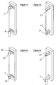
- Figure 7 is an elevational view of a second embodiment of the invention.
- FIG. 8 is a sectional view AA of the device of FIG. 7.
- Figure 9 is a detail view of a third embodiment of the invention.
- Figure 10 illustrates a fourth embodiment of the invention.
- Figure 11 is a sectional view BB of the assembly of Figure 10.
- FIGS 12, 13, 14 and 15 show other equivalent embodiments in which the secondary mast is limited to two fasteners which are attached directly to the antenna.
- Figure 16 is a partial view, in perspective, of another embodiment of the upper attachment means.
- Figure 17 is a detail view of the upper attachment member of the secondary mast.
- Figure 18 shows, in three steps, the use of a temporary guide means.
- Figure 19 is a top view of the guide means.
- the antenna A is fixed on a vertical support mast 1 by two fasteners spaced from each other, respectively upper 2 and lower 6.
- these attachment members are provided on a secondary mast 11 which facilitates the hooking and unhooking maneuvers from a platform B on which is fixed the support mast 1, for example the terrace of a building.
- FIGS. 1 and 2 show schematically the two steps of placing on a support mast 1, an antenna A fixed on a secondary mast 11 which advantageously extends downwards to facilitate maneuvering by an operator who can lift and orient the antenna by means of handles 13,13 'mounted on the lower part of the secondary mast 11 and sufficiently spaced to allow the maneuvering of the mast 11 carrying the antenna A at its upper part.
- the upper attachment member 2 is placed at the upper part of the secondary mast 11, for example towards the middle of the height occupied by the antenna A. It consists, in the embodiment of FIGS. 1 to 6, of an enlarged support piece 21 having, preferably, an outer face 22 of frustoconical shape opening upwards.
- a hooking means 4 which can be constituted, as shown in FIG. 4, of a plate 40 on which are formed a plurality of housings 41 which may each consist of a flange 42 having an inner face having a frustoconical hollow profile, of shape conjugate to that of the support piece 21.
- the plate 40 carries three housings 41 centered on three vertical planes P1, P2, P3 regularly spaced 120 ° ( Figure 4).
- Each flange 42 is provided with a radial slot 43 centered in the corresponding plane P and of a width slightly greater than that of the shaft end 20 on which the frustoconical support piece 21 is mounted and which, in the example shown , constitutes a part of the secondary mast 11 ( Figure 5).
- the secondary mast 11 hooked by the piece 21 to the upper plate 40 is thus suspended vertically along the support mast 1 and is locked in this position by a lower locking means 5 placed in the lower part of the support mast 1 and having two half-flanges 51 clamped to the desired level on the support mast 1 and two half-flanges 52 which are clamped on a lower portion 6 su mast secondary 11 constituting the lower attachment member of the antenna ( Figure 3).
- a kind of snap-fastening of the antenna A has thus been achieved which is attached to the support mast 1 by its upper attachment member 2 while keeping a possibility of rotation about the axis yy 'of the secondary mast 11 for the adjustment in azimuth of the antenna A before blocking the assembly in the selected angular position.
- FIG. 6 shows a variant with an orientable mast, the lower part of which fits into a female base 14 enabling rotation of the mast 1 and its blocking by clamping means 15.
- This function is very useful when the operator does not have access to the antenna from his work station, for example: mast positioned on the bank of a roof, the rotation function makes it possible to bring back the antenna located above the empty on the roof and thus work safely; mast located in a faerie chimney, the rotation makes it possible to bring back the antenna to the right of the door of access ...
- Figure 7 illustrates a second embodiment for allowing the attachment from the ground of at least one secondary mast 11 antenna support A on a vertical support mast.
- the attachment members respectively upper 2 and lower 6 each comprise a pivot 23,61 mounted at the end of an arm 24,62 fixed transversely to the secondary mast 11. These pivots extend towards the low and are aligned so as to be able to engage, after lifting the antenna; in two aligned orifices 44, 54 respectively formed on an upper plate 40 and a lower plate 50 fixed, one at the top and the other at the bottom of the support mast 1.
- the two arms 24,62 After engagement of the pivots 23, 61, the two arms 24,62 respectively support the two trays 40,50 which thus constitute means for hooking and stopping the secondary mast 11 with the antenna A at the desired level.
- the two orifices 44, 54 are aligned along a vertical axis y 'y around which the assembly of the secondary mast 11 and the antenna A can pivot for the azimuth adjustment after snapping of the pivots 23, 61 into the orifices 44, 54 .
- the lower plate 50 carries on the other hand, a series of spaced holes 56 distributed over a circular sector centered on the axis of the orifice 54 and the lower arm 62 is provided with a hole 63 placed at a distance from the pivot 61 equal to the radius of said sector so as to come into coincidence, successively with one of the holes 56 of the series, which allows, after azimuth adjustment, to block the antenna at the desired orientation by introducing into the two aligned holes 63,56, a bolt 64 tightened by a nut.
- the trays 40, 50 each comprise a plurality of orifices 44, 54 centered in radiating planes, for example three planes P1, P2, P3 to allow the introduction of three individually adjustable antennas in azimuth (FIG. 8).
- FIG. 9 illustrates a third embodiment that allows the attachment from the ground of at least one secondary mast 11 for supporting an antenna A on a vertical support mast 1.
- the attachment means (4) located in upper part comprises a latching means 2 and a locking means (5) at the bottom.
- the upper attachment member 2 comprises a rod 25 which is connected to the upper end of the secondary mast 11 by a conical portion 25 '.
- the operator engages this rod 25, by axial sliding, in a housing 45 of shape conjugate to that of the conical portion 25 'and passing through a plate 40 fixed to the upper part of the mast
- the lower end of the secondary mast 11 passes over a lower plate 50 of the support mast 1 and is provided with a conical hole 65 in which the point of a bolt 55 screwed into a threaded bore plateau 50, the assembly constituting the lower attachment member 6 of the secondary mast 11 which can thus pivot with the antenna about the vertical axis passing through the upper rod 25 and the lower hole 65.
- the assembly can be locked in this orientation by screwing the bolt 55 to engage, by axial sliding, the rod 25 in a hole of the same diameter opening at the upper end of the housing 45 in which the conjugate portion 25 'is locked at the end of the mast 11.
- the front end, before orientation and locking, of the upper end of the secondary mast 11 is made by engaging one into the other of a male element and a female element, while retaining a possibility of pivoting for the azimuth adjustment of the antenna.
- the element of the latching device is constituted by a pivot 46 extending upwards and placed at the end of an arm 40 and the secondary mast 11 consists of a tube provided with an opening 26 'placed below a partition 26 in which is formed an axial hole 27.
- the secondary mast 11 By lifting the secondary mast 11 with the antenna, the operator engages the arm 40 'in the opening 26' to place below the wall 26 the pivot 46 which, by letting down the secondary mast 11, engages in the hole 27, the descent movement being stopped by the support of the partition 26 on the arm 40 ', the assembly thus constituting a means of stopping the antenna at the desired level, with the possibility of rotation around the pivot 46 for azimuth adjustment.
- the secondary mast 11 may be locked in the orientation selected for example by a collar 5 of the type shown in Figures 1 to 6.
- the upper attachment means 4 may comprise a plurality of arms 40 'centered in radiating planes P1, P2, P3 for setting up a plurality of individually adjustable antennas.
- the secondary mast 11 is particularly advantageous for attachment and adjustment of the antenna from the ground, but it would also be possible to attach fasteners 2.6 directly to the antenna. of the same type.
- the secondary mast limited to its functional parts is an integral part of the antenna which is snapped directly onto the attachment means 4 of the vertical support mast and is blocked by the locking means 5.
- FIGs 12,13,14,15 thus show attachment members equivalent to those which have been described, respectively, in Figures 1 and 2, 7, 9, 10, the equivalent means bearing the same references.
- FIGS. 1 to 6 may be the subject of a variant shown in FIGS. 16 and 17.
- the support piece 21 formed at the upper part of the secondary mast 11 has only two enlarged portions 21 'with frustoconical faces, which extend in diametrically opposite directions and the flange 42 formed on the upper plate 40 comprises only two frustoconical bearing faces 42 'separated by two recesses 41' diametrically opposite and centered in a radial plane P.
- the operator introduces from below the upper end of the secondary mast 11 into the central orifice of the flange 42, by passing the enlarged portions 21 'in the recesses 41 'to place the support piece 21 above the collar.
- a temporary guiding means as shown in Figure 18 which applies to a device of the type described above comprising an attachment means 4 and a locking means 5 mounted respectively in the upper part and in the lower part of the support mast 1.
- a temporary guide means 7 placed above the locking means 5 and comprising a guide collar 71 fixed to the mast 1 by a clamping member 72, for example two half-flanges in the manner represented , in plan view, in FIG. 19.
- the guide collar 71 is pivotally mounted about an axis 73 on an arm 74 and limits an oblong hole 70 of length slightly greater than the diameter of the secondary mast 11.
- Figure 18 shows, in three steps, the stall of an antenna.
- step (a) the secondary mast 11 carrying the antenna A is fixed along the support mast 1 by the attachment means 4 and the means The guide collar 71 is then closed around the secondary mast 11.
- step (b) the secondary mast 11 has been raised so as to disengage the upper support member 21.
- the locking means 5 has simply been loosened and ensures the maintenance of the lower end of the secondary mast 11 which is also maintained, above, by the guide means 7, being able, however, to tilt to clear the support piece 21, thanks to the degree of freedom given by the longer length of the oblong hole 70.
- Antenna A is therefore not likely to tip on the side or towards the operator, who can make it descend down the mast 1 by sliding in the loose collars of the locking means 5 and the guide means 7.
- the base 14 su mast support 1 can be equipped with a support 16 on which is supported the lower handle 13 'maneuver the secondary mast 11.
- Such a support makes it possible to avoid any deterioration of the sealing lining of the platform.
Landscapes
- Engineering & Computer Science (AREA)
- General Engineering & Computer Science (AREA)
- Computer Networks & Wireless Communication (AREA)
- Mechanical Engineering (AREA)
- Support Of Aerials (AREA)
Abstract
Description
L'invention a pour objet un dispositif de mât multiple pour des antennes de radiocommunication.The invention relates to a multiple mast device for radio communication antennas.
Le territoire national est couvert de sites de réception et d'émission dans le cadre de maillage de radiocommunication. Si ce maillage est relativement simple en dehors des agglomérations, il n'en est pas de même à l'intérieur des villes.The national territory is covered by reception and transmission sites as part of a radiocommunication network. If this mesh is relatively simple outside the agglomerations, it is not the same inside the cities.
En effet, les émissions sont alors coupées par la présence d' immeubles créant des écrans pour la transmission des signaux.Emissions are then cut off by the presence of buildings creating screens for the transmission of signals.
Il est donc nécessaire d'augmenter le nombre des sites de réception et d'émission des ondes radio.It is therefore necessary to increase the number of reception and transmission sites for radio waves.
Normalement, une antenne doit être placée aussi haut que possible, c'est pourquoi, les sites privilégiés sont situés sur les terrasses des immeubles de grande hauteur, les châteaux d'eau, les silos...Normally, an antenna should be placed as high as possible, which is why the privileged sites are located on the terraces of high-rise buildings, water towers, silos ...
Les sites comprennent d'une part les antennes panneaux dont les dimensions peuvent varier d'une hauteur de 0.60 à 2.70 mètres et une section de 0.40 x 0.15 mètre d'épaisseur pour la réception et l'émission des signaux, et d'autre part des baies électroniques connectées au réseau filaire, qui gèrent les signaux.The sites include on the one hand the panel antennas whose dimensions can vary from a height of 0.60 to 2.70 meters and a section of 0.40 x 0.15 meters of thickness for the reception and the emission of the signals, and on the other hand electronic bays connected to the wired network, which manage the signals.
Les antennes sont fixées sur des mâts métalliques posés sur les terrasses ou bien en applique sur les murs de façade des derniers étages ou sur les murs des édicules techniques des immeubles, châteaux d'eau, silos, ...The antennas are fixed on metal poles placed on the terraces or applied on the walls of facade of the last floors or on the walls of the technical buildings of buildings, water towers, silos, ...
Chaque site d'émission/réception est composé au minimum par trois antennes GSM. Chaque antenne GSM émet/reçoit les signaux sur un secteur de 120°.Each transmission / reception site is composed of at least three GSM antennas. Each GSM antenna transmits / receives signals over a 120 ° sector.
Aujourd'hui dans le cadre du déploiement du nouveau réseau UMTS, les sites d'émission/réception devront être densifiés.Today, as part of the deployment of the new UMTS network, transmission / reception sites will have to be densified.
Actuellement les antennes sont fixées directement sur les mâts par l'intermédiaire de deux organes d'attache tels que des brides situées au niveau bas et au niveau haut de l'antenne.Currently the antennas are attached directly to the masts via two fasteners such as flanges located at the low level and high level of the antenna.
Chaque antenne doit pouvoir être réglée horizontalement (azimut), et verticalement (tilt) par une inclinaison par rapport à la verticale vers la zone où l'on désire transmettre les signaux.Each antenna must be able to be adjusted horizontally (azimuth), and vertically (tilt) by an inclination with respect to the vertical towards the zone where it is desired to transmit the signals.
Généralement les antennes sont posées verticalement. Sur les nouvelles génération d'antennes le tilt est réglé par un dispositif électrique interne à l'antenne. Seul le réglage en azimut est réalisé par une intervention extérieure manuelle.Generally the antennas are placed vertically. On the new generation of antennas the tilt is regulated by an internal electrical device on the antenna. Only the azimuth adjustment is achieved by manual external intervention.
Sur les antennes posées sur les mâts classiques des installations de première génération de déploiement du réseau de téléphonie mobile, pour régler l'azimut d'une antenne le technicien doit monter en tête de mât pour agir sur les brides sommitales de liaison de l'antenne avec le mât.On the antennas placed on the conventional masts of the first-generation mobile network deployment installations, to adjust the azimuth of an antenna the technician must mount at the masthead to act on the antenna uplink top flanges with the mast.
Aujourd'hui un premier procédé de mât rabattable permet le montage de l'antenne depuis le plancher d'assise du mât, par exemple selon les brevets demandes de Bouygues télécom
Un second procédé composé d'un mât principal porteur et de plusieurs mâts secondaires rayonnants permet de monter plusieurs antennes sur un ensemble: brevets et demandes de brevets Bouygues télécom
Dans ce second type de mâts le montage et la maintenance des antennes sont réalisés en hauteur sur échelle par des opérateurs équipés de harnais de sécurité.In this second type of masts the mounting and maintenance of the antennas are carried out in height on a scale by operators equipped with safety harnesses.
Le premier procédé de mât rabattable ne permet pas, ou que très difficilement, le montage et le réglage en azimut de trois antennes ou plus sur un même mât.The first method of folding mast does not allow, or very difficult, mounting and azimuth adjustment of three or more antennas on the same mast.
Le second procédé composé d'un mât porteur principal avec des mâts secondaires rayonnants permet le montage de plusieurs antennes mais conduit à maintenir et pérenniser la création de postes de travail en hauteur.The second method consisting of a main carrier mast with radiating secondary masts allows the mounting of several antennas but leads to maintain and sustain the creation of workstations at height.
L'invention a pour but de créer un mât porteur vertical fixe ou bien rotatif, permettant de supporter au minimum une antenne, dont la mise en oeuvre, le réglage en azimut et la maintenance sont effectués depuis le plancher par une équipe de techniciens. Ainsi, l'emploi d'échelle, escabeau, emmarchement... n'est plus nécessaire pour la mise en oeuvre, le réglage et la maintenance du matériel.The object of the invention is to create a vertical fixed or rotary bearing mast, enabling at least one antenna to be supported, the implementation of which, the adjustment in azimuth and the maintenance are carried out from the floor by a team of technicians. Thus, the use of ladder, stepladder, step ... is no longer necessary for the implementation, adjustment and maintenance of equipment.
En outre, ceci permet de supprimer les risques du travail en hauteur par des opérateurs spécialisés, équipés d'un système de sécurité, constitué par un harnais solidaire d'un mousqueton fixé sur un coulisseau anti-chute intégré à l'échelle, fixée sur le mât porteur principal.In addition, this eliminates the risk of work at height by specialized operators, equipped with a safety system, consisting of a harness secured to a carabiner attached to a scale-integrated fall arrestor, fixed on the main carrier mast.
La mise en oeuvre des antennes depuis le plancher a aussi pour corollaire de supprimer l'échelle fixée au mât, nécessaire à la maintenance des antennes, ainsi que les bracons situés de part et d'autre du mât et qui assurent sa stabilité latérale sous l'action des efforts produits par la chute d'un homme.The implementation of the antennas from the floor also has the corollary of removing the ladder attached to the mast, necessary for the maintenance of the antennas, and the bridges located on either side of the mast and which ensure its lateral stability under the action of the efforts produced by the fall of a man.
On connaît déjà, par le document
Après ce réglage en azimut, l'antenne est fixée le long du mât par un organe de blocage monté en partie basse du mât et permettant le réglage d'inclinaison. Ce réglage dit « tilt » peut, aussi, être effectué maintenant par des moyens électroniques intégrés à l'antenne avec commande en partie basse de celle-ci.After this adjustment in azimuth, the antenna is fixed along the mast by a locking member mounted at the bottom of the mast and allowing adjustment of inclination. This adjustment said "tilt" can also be done now by electronic means integrated into the antenna with control in the lower part thereof.
Un tel dispositif ne permet, cependant, pas d'accrocher sur le mât plusieurs antennes puisque le réglage en azimut de l'antenne dépend de sa position le long de la couronne.Such a device does not allow, however, to hang on the mast several antennas since the azimuth setting of the antenna depends on its position along the crown.
L'invention a pour objet de résoudre l'ensemble de ces problèmes grâce à un dispositif permettant, d'une part, de fixer éventuellement plusieurs antennes sur un même mât porteur et, d'autre part, de régler séparément chaque antenne en azimut à partir du sol.The object of the invention is to solve all these problems by means of a device making it possible, on the one hand, to possibly fix several antennas on the same carrier mast and, on the other hand, to separately adjust each antenna in azimuth to from the ground.
L'invention concerne donc, d'une façon générale, un dispositif de fixation d'au moins une antenne sur un mât porteur à axe vertical, fixé à sa base sur une plate forme, comportant, en partie haute du mât porteur, des moyens d'accrochage d'un organe supérieur d'attache de l'antenne et, en partie basse, des moyens de blocage le long du mât porteur d'un organe inférieur d'attache de l'antenne le long du mât à un niveau déterminé au dessus de la plate forme.The invention thus relates generally to a device for fixing at least one antenna on a vertical axis carrier mast, fixed at its base on a platform, comprising, in the upper part of the support mast, means attachment of an upper attachment member of the antenna and, in the lower part, locking means along the mast carrying a lower attachment member of the antenna along the mast at a predetermined level above the platform.
Conformément à l'invention, les moyens d'accrochage sur le mât et l'organe supérieur d'attache de l'antenne comportent, l'un un élément mâle et l'autre un élément femelle qui s'engagent l'un dans l'autre par coulissement suivant un axe sensiblement vertical jusqu'à une position d'arrêt de l'antenne à un niveau souhaité au dessus de la plate forme, avec possibilité de rotation autour dudit axe pour le réglage en azimut de l'antenne avant blocage le long du mât.According to the invention, the attachment means on the mast and the upper fastening member of the antenna comprise, one a male element and the other a female element which engage one in the slidably along a substantially vertical axis to a stopping position of the antenna at a desired level above the platform, with possibility of rotation about said axis for azimuth adjustment of the antenna before blocking along the mast.
Dans un premier mode de réalisation, l'organe supérieur d'attache de l'antenne comporte une pièce d'appui élargie qui vient se placer au dessus d'un logement ménagé sur une collerette fixée en partie haute du mât et prend appui, par coulissement axial vers le bas, sur ladite collerette dans la position d'arrêt de l'antenne au niveau souhaité.In a first embodiment, the upper attachment member of the antenna comprises an enlarged support piece which is placed above a housing provided on a collar fixed at the top of the mast and is supported by axial sliding downward on said flange in the off position of the antenna at the desired level.
De façon particulièrement avantageuse, l'organe supérieur d'attache de l'antenne forme au moins un bout d'arbre sur lequel est ménagé la partie d'appui élargie et que la collerette est munie d'une fente de largeur un peu supérieure à celle du bout d'arbre pour la mise en place de la partie d'appui au dessus du logement.In a particularly advantageous manner, the upper attachment member of the antenna forms at least one end of a shaft on which the enlarged support portion is formed and that the collar is provided with a slit of a width slightly greater than that of the shaft end for the establishment of the support portion above the housing.
Selon une variante, la pièce d'appui comporte deux parties élargies qui s'étendent en saillie de part et d'autre d'un arbre d'attache de l'antenne et que la collerette comporte deux faces d'appui en forme de secteurs diamétralement opposés, entre lesquelles sont ménagés deux évidements pour l'enfilement vers le haut de l'arbre d'attache en faisant passer les parties élargies dans les évidements, lesdites parties élargies revenant se poser sur les deux faces d'appui après rotation d'un quart de tour de l'arbre avec l'antenne pour l'arrêt de celle-ci au niveau souhaité.According to one variant, the support piece comprises two enlarged parts which project from both sides of an antenna attachment shaft and that the collar comprises two faces. in the form of diametrically opposed sectors, between which are provided two recesses for the upward threading of the attachment shaft by passing the enlarged parts in the recesses, said enlarged parts returning to land on both sides after quarter-turn rotation of the shaft with the antenna to stop it at the desired level.
Dans un autre mode de réalisation, les deux organes d'attache, respectivement supérieur et inférieur de l'antenne comportent chacun un pivot monté à l'extrémité d'un bras transversal et s'étendant vers le bas, lesdits pivots étant alignés et s'engageant respectivement dans deux orifices alignés ménagés respectivement sur deux plateaux supports écartés, fixés, l'un en partie haute et l'autre en partie basse du mât, lesdits orifices alignés définissant un axe de pivotement de l'antenne pour le réglage en azimut de celle-ci.In another embodiment, the two attachment members, respectively upper and lower antenna each comprise a pivot mounted at the end of a transverse arm and extending downwards, said pivots being aligned and s engaging respectively in two aligned orifices provided respectively on two spaced apart, fixed support plates, one in the upper part and the other in the lower part of the mast, said aligned orifices defining an axis of pivoting of the antenna for the azimuth adjustment of it.
Dans encore un autre mode de réalisation, l'organe d'attache supérieur de l'antenne comporte une première tige s'étendant vers le haut et s'engageant, de bas en haut, dans un logement ménagé sur un plateau fixé en partie haute du mât et que l'organe d'attache inférieur comporte un orifice dans lequel s'engage, de bas en haut une seconde tige montée sur un plateau inférieur fixé en partie basse du mât et déplaçable verticalement pour le soulèvement de l'antenne après engagement de la première tige jusqu'à venir en butée sur le fond du logement dans une position d'arrêt de l'antenne au niveau souhaité.In yet another embodiment, the upper attachment member of the antenna comprises a first rod extending upwards and engaging, from below upwards, in a housing formed on a plate fixed in the upper part. of the mast and that the lower attachment member has an orifice in which engages, from below upwards a second rod mounted on a lower plate fixed at the bottom of the mast and movable vertically for lifting the antenna after engagement the first rod to abut on the bottom of the housing in a stopping position of the antenna at the desired level.
De préférence, les deux organes d'attache de l'antenne sont ménagés sur deux partie écartées d'un mât secondaire sur lequel est fixé l'antenne. Mais il peuvent aussi être fixés directement sur deux zones écartées l'une de l'autre de l'antenne.Preferably, the two attachment members of the antenna are provided on two parts spaced apart from a secondary mast on which the antenna is fixed. But they can also be fixed directly on two zones separated from each other of the antenna.
Un avantage essentiel de l'invention réside dans le fait qu'elle permet la fixation de plusieurs antennes sur un même mât porteur et leur réglage individuel en azimut à partir de la plate forme.An essential advantage of the invention lies in the fact that it allows the attachment of several antennas on the same carrier mast and their individual adjustment in azimuth from the platform.
En effet, le mât porteur peut être équipé de plusieurs moyens d'accrochage et de plusieurs moyens de blocage disposés deux à deux dans des plans rayonnants autour du mât, chaque antenne pouvant être réglée en azimut par rotation autour d'un axe vertical avant blocage le long du mât.Indeed, the support mast can be equipped with several attachment means and several locking means arranged two to two in radiating planes around the mast, each antenna being adjustable in azimuth by rotation about a vertical axis before blocking along the mast.
Le dispositif de fixation conçu conformément à l'invention présente un certain nombre d'avantages.The fastening device designed in accordance with the invention has a number of advantages.
Il permet la mise en oeuvre et le réglage rapide en azimut des antennes de radio communication depuis le sol, sans utilisation d'aides par échelle, escabeau... ce qui réduit le temps d'intervention des opérateurs sur les toitures, et conséquence plus importante, il supprime les travaux en hauteur sur les mâts, permettant ainsi de réduire les risques d'accidents du travail.It allows the implementation and fast azimuth adjustment of radio communication antennas from the ground, without the use of ladders, stepladders ... which reduces the intervention time of the operators on the roofs, and consequently more important, it eliminates the work at height on the masts, thus reducing the risk of accidents at work.
La suppression des bracons en tête de mât et de l'échelle associée au mât, minimise les coûts des investissements et permet une meilleure intégration paysagère dans l'environnement.The removal of masthead pontoons and the ladder associated with the mast minimizes investment costs and allows for better landscape integration into the environment.
En outre on notera que les solutions proposées permettant la mise en place des antennes depuis le sol ont l'avantage d'être particulièrement simple et économique par exemple, une lumière débouchant sur le périmètre du moyen assurant l'accrochage.In addition, it should be noted that the proposed solutions for placing antennas from the ground have the advantage of being particularly simple and economical, for example, a light emerging on the perimeter of the means ensuring the attachment.
Mais l'invention couvre aussi d'autres caractéristiques avantageuses qui apparaîtront dans la description détaillée de certains modes de réalisation donnés à titre de simples exemples et représentés sur les dessins annexés.But the invention also covers other advantageous features which will appear in the detailed description of certain embodiments given by way of simple examples and shown in the accompanying drawings.
La figure 1 est une vue schématique en élévation de la mise en place d'un mât secondaire portant une antenne sur un mât porteur vertical.Figure 1 is a schematic elevational view of the establishment of a secondary mast carrying an antenna on a vertical support mast.
La figure 2 est une vue en élévation de l'ensemble après accrochage du mât secondaire et de l'antenne.Figure 2 is an elevational view of the assembly after attachment of the secondary mast and the antenna.
La figure 3 est une vue d'ensemble, en perspective du mât porteur vertical, mât secondaire et antenne, avec les moyens assurant l'accrochage et le blocage sur le mât porteur.Figure 3 is an overall view, in perspective of the vertical support mast, secondary mast and antenna, with the means ensuring the attachment and locking on the support mast.
La figure 4 est une vue de détail du moyen assurant l'accrochage.Figure 4 is a detail view of the means ensuring the attachment.
La figure 5 est une vue de détail d'un moyen d'encliquetage du mât secondaire sur le mât porteur vertical.Figure 5 is a detailed view of a latching means of the secondary mast on the vertical support mast.
La figure 6 illustre une configuration qui peut être réalisée avec un mât porteur vertical rotatif.FIG. 6 illustrates a configuration that can be realized with a vertical rotating support mast.
La figure 7 est une vue en élévation d'un second mode de réalisation de l'invention.Figure 7 is an elevational view of a second embodiment of the invention.
La figure 8 est une vue en coupe AA du dispositif de la figure 7.FIG. 8 is a sectional view AA of the device of FIG. 7.
La figure 9 est une vue de détail d'un troisième mode de réalisation de l'invention.Figure 9 is a detail view of a third embodiment of the invention.
La figure 10 illustre un quatrième mode de réalisation de l'invention.Figure 10 illustrates a fourth embodiment of the invention.
La figure 11 est une vue en coupe BB de l'assemblage de la figure 10.Figure 11 is a sectional view BB of the assembly of Figure 10.
Les figures 12, 13, 14 et 15 représentent d'autres modes de réalisation équivalents dans lesquels le mât secondaire est limité aux deux organes d'attache qui sont fixés directement sur l'antenne.Figures 12, 13, 14 and 15 show other equivalent embodiments in which the secondary mast is limited to two fasteners which are attached directly to the antenna.
La figure 16 est une vue partielle, en perspective, d'un autre mode de réalisation du moyen d'accrochage supérieur.Figure 16 is a partial view, in perspective, of another embodiment of the upper attachment means.
La figure 17 est une vue de détail de l'organe supérieur d'attache du mât secondaire.Figure 17 is a detail view of the upper attachment member of the secondary mast.
La figure 18 montre, en trois étapes, l'utilisation d'un moyen de guidage provisoire.Figure 18 shows, in three steps, the use of a temporary guide means.
La figure 19 est une vue de dessus du moyen de guidage.Figure 19 is a top view of the guide means.
D'une façon générale, l'antenne A est fixée sur un mât porteur vertical 1 par deux organes d'attache écartés l'un de l'autre, respectivement supérieur 2 et Inférieur 6. De préférence,comme le montre les figures 1 à 11, ces organes d'attache sont ménagés sur un mât secondaire 11 qui facilite les manoeuvres d'accrochage et de décrochage à partir d'une plate forme B sur laquelle est fixé le mât porteur 1, par exemple la terrasse d'un immeuble.In general, the antenna A is fixed on a
Cependant il est possible également de fixer directement les organes d'attache 2,6 sur l'antenne A. Comme le montrent les figures 12 à 15, toutes les dispositions qui vont maintenant êtres décrites sont applicables également à ces cas où le mât secondaire est limité à ses parties fonctionnelles portant les deux organes d'attache et fait donc partie intégrante de l'antenne.However it is also possible to directly fix the
Les figures 1 et 2 montrent schématiquement les deux étapes de mise en place sur un mât porteur 1, d'une antenne A fixée sur un mât secondaire 11 qui s'étend avantageusement vers le bas pour faciliter la manoeuvre par un opérateur qui peut soulever et orienter l'antenne au moyen de poignées 13,13' montées sur la partie inférieure du mât secondaire 11 et suffisamment écartées pour permettre la manoeuvre du mât 11 portant l'antenne A à sa partie supérieure.FIGS. 1 and 2 show schematically the two steps of placing on a
L'organe d'attache supérieur 2 est placé à la partie supérieure du mât secondaire 11, par exemple vers le milieu de la hauteur occupée par l'antenne A. Il est constitué, dans le mode de réalisation des figures 1 à 6, d'une pièce d'appui élargie 21 ayant, de préférence, une face externe 22 de forme tronconique s'ouvrant vers le haut. A la partie supérieure du mât porteur 1 est fixé un moyen d'accrochage 4 qui peut être constitué, comme le montre la figure 4, d'un plateau 40 sur lequel sur lequel sont ménagés plusieurs logements 41 qui peuvent être constitués chacun d'une collerette 42 ayant une face interne ayant un profil creux tronconique, de forme conjuguée à celle de la pièce d'appui 21.The
Dans l'exemple représenté, le plateau 40 porte trois logements 41 centrés sur trois plans verticaux P1,P2,P3 régulièrement écartés de 120° (figure 4).In the example shown, the
Chaque collerette 42 est munie d'une fente radiale 43 centrée dans le plan correspondant P et de largeur un peu supérieure à celle du bout d'arbre 20 sur lequel est montée la pièce d'appui tronconique 21 et qui, dans l'exemple représenté, constitue une partie du mât secondaire 11 (figure 5).Each
Pour la mise en place sur le mât porteur 1 d'une antenne A fixée sur un mât secondaire 11, l'opérateur soulève celui-ci au moyen des poignées écartées 13,13' et approche sa partie supérieure du plateau 40 pour engager dans la fente 43 d'une collerette 42 le bout d'arbre 20 portant la pièce d'appui 21 qui se trouve ainsi au dessus du logement 41 (figure 1).For the establishment on the
L'opérateur ramène alors le mât secondaire 11 le long du mât porteur 1 en laissant redescendre la pièce élargie 21 qui vient prendre appui sur la collerette 42 constituant, ainsi, un moyen d'arrêt du mât secondaire 11 au niveau souhaité pour l'antenne A.The operator then returns the
Le mât secondaire 11 accroché par la pièce 21 au plateau supérieur 40 est ainsi suspendu verticalement le long du mât porteur 1 et est bloqué dans cette position par un moyen de blocage inférieur 5 placé en partie basse du mât porteur 1 et comportant deux demi brides 51 serrées au niveau voulu sur le mât porteur 1 et deux demi brides 52 qui se serrent sur une partie inférieure 6 su mât secondaire 11 constituant l'organe d'attache inférieur de l'antenne (figure 3).The
On a ainsi réalisé une sorte d'encliquetage de l'antenne A qui est accrochée au mât porteur 1 par son organe d'attache supérieur 2 en conservant une possibilité de rotation autour de l'axe yy' du mât secondaire 11 pour le réglage en azimut de l'antenne A avant blocage de l'ensemble dans la position angulaire choisie.A kind of snap-fastening of the antenna A has thus been achieved which is attached to the
D'autre part, il est possible de placer sur le plateau 40 au moins trois antennes centrées dans des plans rayonnants P1,P2,P3 et pouvant être encliquetées et orientées individuellement à partir de la plate forme B.On the other hand, it is possible to place on the
La figure 6 montre une variante avec un mât orientable dont la partie inférieure s'emboîte dans une embase femelle 14 permettant la rotation du mât 1 et son blocage par des moyens de serrage 15.FIG. 6 shows a variant with an orientable mast, the lower part of which fits into a
Cette fonction est très utile lorsque l'opérateur n'a pas accès à l'antenne depuis son poste de travail, par exemple: mât positionné sur la rive d'une toiture, la fonction rotation permet de ramener l'antenne située au dessus du vide sur la toiture et ainsi travailler en toute sécurité; mât situé dans une fausse cheminée, la rotation permet de ramener l'antenne au droit de la porte d'accès...This function is very useful when the operator does not have access to the antenna from his work station, for example: mast positioned on the bank of a roof, the rotation function makes it possible to bring back the antenna located above the empty on the roof and thus work safely; mast located in a faerie chimney, the rotation makes it possible to bring back the antenna to the right of the door of access ...
La figure 7 illustre un second mode de réalisation pour permettre l'accrochage depuis le sol d'au moins un mât secondaire 11 support d'antenne A sur un mât porteur vertical.Figure 7 illustrates a second embodiment for allowing the attachment from the ground of at least one
Dans ce cas, les organes d'attache, respectivement supérieur 2 et inférieur 6 comportent chacun un pivot 23,61 monté à l'extrémité d'un bras 24,62 fixé transversalement sur le mât secondaire 11. Ces pivots s'étendent vers le bas et sont alignés de façon à pouvoir s'engager, après soulèvement de l'antenne; dans deux orifices alignés 44,54 ménagés respectivement sur un plateau supérieur 40 et un plateau inférieur 50 fixés, l'un en partie haute et l'autre en partie basse du mât porteur 1. Après engagement des pivots 23,61, les deux bras 24,62 prennent appui respectivement sur les deux plateaux 40,50 qui constituent ainsi des moyens d'accrochage et d'arrêt du mât secondaire 11 avec l'antenne A au niveau voulu. Les deux orifices 44,54 sont alignés suivant un axe vertical y'y autour duquel l'ensemble du mât secondaire 11 et de l'antenne A peut pivoter pour le réglage en azimut après encliquetage des pivots 23,61 dans les orifices 44,54.In this case, the attachment members, respectively upper 2 and lower 6 each comprise a
Le plateau inférieur 50 porte d'autre part, une série de trous écartés 56 répartis sur un secteur circulaire centré sur l'axe de l'orifice 54 et le bras inférieur 62 est muni d'un trou 63 placé à une distance du pivot 61 égale au rayon dudit secteur de façon à venir en coïncidence, successivement avec l'un des trous 56 de la série, ce qui permet, après réglage en azimut, de bloquer l'antenne à l'orientation voulue en introduisant dans les deux trous alignés 63,56, un boulon 64 serré par un écrou.The
Comme précédemment, les plateaux 40,50 comportent chacun plusieurs orifices 44,54 centrés dans des plans rayonnants, par exemple trois plans P1,P2,P3 pour permettre la mise en place de trois antennes réglables individuellement en azimut (figure 8).As before, the
La figure 9, illustre un troisième mode de réalisation qui permet l'accrochage depuis le sol d'au moins un mât secondaire 11 de support d'une antenne A sur un mât porteur vertical 1. Le moyen d'accrochage (4) situé en partie haute comporte un moyen d'encliquetage 2 et un moyen de blocage (5) en partie basse.FIG. 9 illustrates a third embodiment that allows the attachment from the ground of at least one
Dans ce cas, l'organe supérieur d'attache 2 comporte une tige 25 qui se raccorde à l'extrémité supérieure du mât secondaire 11 par une partie conique 25'.In this case, the
En soulevant le mât secondaire 11 avec l'antenne, l'opérateur engage cette tige 25, par coulissement axial, dans un logement 45 de forme conjuguée à celle de la partie conique 25' et traversant un plateau 40 fixé à la partie supérieure du mât porteur 1. L'extrémité inférieure du mât secondaire 11 passe au dessus 'un plateau inférieur 50 du mât porteur 1 et est munie d'un trou conique 65 dans lequel s'engage la pointe d'un boulon 55 vissé dans un alésage fileté du plateau 50, l'ensemble constituant l'organe d'attache inférieur 6 du mât secondaire 11 qui peut ainsi pivoter avec l'antenne autour de l'axe vertical passant par la tige supérieure 25 et le trou inférieur 65.By lifting the
Après réglage en azimut de l'antenne, l'ensemble peut être bloqué dans cette orientation en vissant le boulon 55 pour engager, par coulissement axial, la tige 25 dans un trou de même diamètre s'ouvrant à l'extrémité supérieure du logement 45 dans lequel vient se bloquer la partie conjuguée 25', à l'extrémité du mât 11.After azimuth adjustment of the antenna, the assembly can be locked in this orientation by screwing the
Ainsi, dans tous les cas, on réalise un encliquetage préalable, avant orientation et blocage, de l'extrémité supérieure du mât secondaire 11 par engagement l'un dans l'autre d'un élément mâle et d'un élément femelle, en conservant une possibilité de pivotement pour le réglage en azimut de l'antenne.Thus, in all cases, the front end, before orientation and locking, of the upper end of the
L'invention n'est, cependant, pas limitée aux divers modes de réalisation qui viennent d'être décrits, des modes équivalents pouvant être employés en restant dans le cadre de protection défini par les revendications.The invention is, however, not limited to the various embodiments that have just been described, equivalent modes that can be used within the scope of protection defined by the claims.
Par exemple, dans le cas représenté sur les figures 10 et 11, l'élément du dispositif d'encliquetage est constitué par un pivot 46 s'étendant vers le haut et placé à l'extrémité d'un bras 40 et le mât secondaire 11 est constitué d'un tube muni d'une ouverture 26' placée au dessous d'une cloison 26 dans laquelle est ménagé un trou axial 27.For example, in the case shown in Figures 10 and 11, the element of the latching device is constituted by a
Par soulèvement du mât secondaire 11 avec l'antenne, l'opérateur engage le bras 40' dans l'ouverture 26' pour placer au dessous de la cloison 26 le pivot 46 qui, en laissant redescendre le mât secondaire 11, s'engage dans le trou 27, le mouvement de descente étant arrêté par l'appui de la cloison 26 sur le bras 40', l'ensemble constituant ainsi un moyen d'arrêt de l'antenne au niveau souhaité, avec possibilité de rotation autour du pivot 46 pour le réglage en azimut. Le mât secondaire 11 peut être bloqué dans l'orientation choisie par exemple par un collier 5 du type représenté sur les figures 1 à 6.By lifting the
Comme précédemment, le moyen d'accrochage supérieur 4 peut comporter plusieurs bras 40' centrés dans des plans rayonnants P1,P2,P3 pour la mise en place de plusieurs antennes réglables individuellement.As previously, the upper attachment means 4 may comprise a plurality of arms 40 'centered in radiating planes P1, P2, P3 for setting up a plurality of individually adjustable antennas.
Par ailleurs, comme indiqué plus haut, le mât secondaire 11 est particulièrement avantageux pour l'accrochage et le réglage de l'antenne à partir du sol mais il serait aussi possible de fixer directement sur l'antenne des organes d'attache 2,6 du même type.Moreover, as indicated above, the
Ainsi le mât secondaire limité à ses parties fonctionnelles fait partie intégrante de l'antenne qui vient s'encliqueter directement sur les moyens d'accrochage 4 du mât porteur vertical et est bloquée par le moyen de blocage 5.Thus the secondary mast limited to its functional parts is an integral part of the antenna which is snapped directly onto the attachment means 4 of the vertical support mast and is blocked by the locking means 5.
Les figures 12,13,14,15 montrent ainsi, des organes d'attache équivalents à ceux qui ont été décrits en référence, respectivement, aux figures 1 et 2, 7, 9, 10, les moyens équivalents portant les mêmes références.Figures 12,13,14,15 thus show attachment members equivalent to those which have been described, respectively, in Figures 1 and 2, 7, 9, 10, the equivalent means bearing the same references.
De même, le mode de réalisation des figures 1 à 6 peut faire l'objet d'une variante représentée sur les figures 16 et 17.Likewise, the embodiment of FIGS. 1 to 6 may be the subject of a variant shown in FIGS. 16 and 17.
Dans ce cas, la pièce d'appui 21 ménagée à la partie supérieure du mât secondaire 11 comporte seulement deux parties élargies 21' à faces tronconiques, qui s'étendent dans des directions diamétralement opposées et la collerette 42 ménagée sur le plateau supérieur 40 comporte seulement deux faces d'appui tronconiques 42' séparées par deux évidements 41' diamétralement opposés et centrés dans un plan radial P.In this case, the
Pour la mise en place de l'antenne sur le mât porteur 1, l'opérateur introduit par le bas l'extrémité supérieure du mât secondaire 11 dans l'orifice central de la collerette 42, en faisant passer les parties élargies 21' dans les évidements 41' pour placer la pièce d'appui 21 au dessus de la collerette.For the introduction of the antenna on the
En faisant tourner le mât secondaire 11 autour de son axe, les parties élargies 21' se placent au dessus des faces d'appui 42' de la collerette 42 et viennent reposer sur celles-ci dans la position d'accrochage de l'antenne au niveau voulu. Cette disposition permet de supprimer la fente 43 en conservant une certaine possibilité de pivotement pour le réglage en azimut.By rotating the
Tous ces modes de réalisation permettent donc, de fixer plusieurs antennes de manière rayonnantes sur le mât porteur avec la possibilité de les régler individuellement en azimut à partir de la plate forme.All these embodiments therefore make it possible to fix several antennas in a radiating manner on the carrier mast with the possibility of setting them individually in azimuth from the platform.
Pour effectuer les manoeuvres en toute sécurité et éviter le basculement de l'antenne au moment de l'accrochage ou du décrochage, il peut être avantageux d'utiliser un moyen de guidage provisoire de la façon représentée sur la figure 18 qui s'applique à un dispositif du type décrit plus haut comportant un moyen d'accrochage 4 et un moyen de blocage 5 montés respectivement en partie haute et en partie basse du mât porteur 1.To perform maneuvers safely and prevent the antenna from tilting at the time of hooking or unhitching, it may be advantageous to use a temporary guiding means as shown in Figure 18 which applies to a device of the type described above comprising an attachment means 4 and a locking means 5 mounted respectively in the upper part and in the lower part of the
Celui-ci est alors équipé d'un moyen de guidage provisoire 7 placé au dessus du moyen de blocage 5 et comportant un collier de guidage 71 fixé sur le mât 1 par un organe de serrage 72, par exemple deux demi brides de la façon représentée, en vue de dessus, sur la figure 19.This is then equipped with a temporary guide means 7 placed above the locking means 5 and comprising a
Le collier de guidage 71 est monté pivotant autour d'un axe 73 sur un bras 74 et limite un trou oblong 70 de longueur un peu supérieure au diamètre du mât secondaire 11.The
La figure 18 montre, en trois étapes, le décrochage d'une antenne.Figure 18 shows, in three steps, the stall of an antenna.
A l'étape (a), le mât secondaire 11 portant l'antenne A est fixé le long du mât porteur 1 par le moyen d'accrochage 4 et le moyen de blocage 5. Le collier de guidage 71 est alors refermé autour du mât secondaire 11.In step (a), the
A l'étape (b), on a soulevé le mât secondaire 11 de façon à décrocher la pièce d'appui supérieure 21. Le moyen de blocage 5 a été simplement desserré et assure le maintien de l'extrémité inférieure du mât secondaire 11 qui est également maintenu, au dessus, par le moyen de guidage 7, en pouvant, cependant, s'incliner pour dégager la pièce d'appui 21, grâce au degré de liberté donné par la longueur plus grande du trou oblong 70.In step (b), the
L'antenne A ne risque donc pas de basculer sur le coté ou vers l'opérateur, qui peut la faire faire descendre le long du mât 1 en coulissant dans les colliers desserrés du moyen de blocage 5 et du moyen de guidage 7.Antenna A is therefore not likely to tip on the side or towards the operator, who can make it descend down the
Ce mouvement de descente peut se poursuivre dans l'étape (c) jusqu'à ce que l'extrémité inférieure du mât secondaire 11 prenne appui sur le sol. Avantageusement, l'embase 14 su mât porteur 1 peut être équipée d'un support 16 sur lequel vient prendre appui la poignée inférieure 13' de manoeuvre du mât secondaire 11.This descent movement can continue in step (c) until the lower end of the
Un tel support permet d'éviter une détérioration éventuelle du revêtement d'étanchéité de la plate forme.Such a support makes it possible to avoid any deterioration of the sealing lining of the platform.
Il est alors possible, en toute sécurité, d'ouvrir les colliers 51 et 71 des moyens de blocage 5 et de guidage 7 pour libérer le mât secondaire 11 qui peut alors basculer à l'horizontale en pivotant sur les poignées 13'.It is then possible, safely, to open the
Claims (12)
Applications Claiming Priority (1)
| Application Number | Priority Date | Filing Date | Title |
|---|---|---|---|
| FR0508412A FR2889624B1 (en) | 2005-08-08 | 2005-08-08 | MAT ENCLICABLE RADIO COMMUNICATION ANTENNA SUPPORT |
Publications (1)
| Publication Number | Publication Date |
|---|---|
| EP1753075A1 true EP1753075A1 (en) | 2007-02-14 |
Family
ID=36149061
Family Applications (1)
| Application Number | Title | Priority Date | Filing Date |
|---|---|---|---|
| EP06291273A Withdrawn EP1753075A1 (en) | 2005-08-08 | 2006-08-07 | Mast snap fit support for radio communication antenna |
Country Status (2)
| Country | Link |
|---|---|
| EP (1) | EP1753075A1 (en) |
| FR (1) | FR2889624B1 (en) |
Cited By (11)
| Publication number | Priority date | Publication date | Assignee | Title |
|---|---|---|---|---|
| AT503466B1 (en) * | 2006-03-16 | 2009-02-15 | Kremsmueller Industrieanlagenb | STRUCTURE FOR SECTOR ANTENNAS |
| ITVR20090117A1 (en) * | 2009-07-30 | 2011-01-31 | Mastec S R L | ANTENNA DOOR |
| GB2474605A (en) * | 2009-10-09 | 2011-04-20 | Fasmetrics Ltd | Antenna mast system and mounting apparatus |
| WO2011127988A1 (en) * | 2010-04-14 | 2011-10-20 | Telefonaktiebolaget L M Ericsson (Publ) | An antenna attachment arrangement, a module comprising such an arrangement and an antenna mast arrangement |
| GB2480168A (en) * | 2009-10-09 | 2011-11-09 | Fasmetrics Ltd | Antenna mast system and mounting apparatus |
| US9728849B2 (en) | 2011-07-15 | 2017-08-08 | Fasmetrics S.A. | Antenna alignment apparatus and method |
| US9893410B2 (en) | 2012-05-18 | 2018-02-13 | Fasmetrics S.A. | Apparatus and method for accurate and precise positioning of cellular antennas |
| CN110274375A (en) * | 2019-07-18 | 2019-09-24 | 宁波奥克斯电气股份有限公司 | A kind of pipeline fixed block, air-conditioner outdoor unit and air conditioner |
| CN114300825A (en) * | 2021-12-29 | 2022-04-08 | 中国电信股份有限公司 | Indoor communication device |
| GB2579977B (en) * | 2017-08-15 | 2022-07-20 | Commscope Design & Integration Uk Ltd | Antenna mounting bracket assembly |
| CN115663451A (en) * | 2022-11-30 | 2023-01-31 | 武汉船舶通信研究所(中国船舶重工集团公司第七二二研究所) | Guiding type installation method for insulator on antenna |
Families Citing this family (1)
| Publication number | Priority date | Publication date | Assignee | Title |
|---|---|---|---|---|
| CN109216869B (en) * | 2018-09-21 | 2024-04-30 | 中电科海洋信息技术研究院有限公司 | Fixing device for fixing GPS antenna |
Citations (5)
| Publication number | Priority date | Publication date | Assignee | Title |
|---|---|---|---|---|
| FR2558203A3 (en) * | 1982-09-29 | 1985-07-19 | Garami Eugene | Adjustable swing door |
| FR2733633A1 (en) * | 1995-04-28 | 1996-10-31 | Telecommunications Internation | Directional azimuth antenna orientation device esp. for cellular radio communication |
| US5620272A (en) * | 1995-05-10 | 1997-04-15 | Sheng; Chim-Yuem | Adjustable joint assembly for ladder sections |
| FR2815477A1 (en) * | 2000-10-16 | 2002-04-19 | Bouygues Telecom Sa | Supports for more than one relay antennas of a cellular telecommunication radio on a mast and device to tune the orientation of such an antenna. |
| FR2818810A1 (en) * | 2000-12-22 | 2002-06-28 | Coprebat | Adjustable antenna mount has separate orthogonal settings can be set from ground |
-
2005
- 2005-08-08 FR FR0508412A patent/FR2889624B1/en not_active Expired - Fee Related
-
2006
- 2006-08-07 EP EP06291273A patent/EP1753075A1/en not_active Withdrawn
Patent Citations (5)
| Publication number | Priority date | Publication date | Assignee | Title |
|---|---|---|---|---|
| FR2558203A3 (en) * | 1982-09-29 | 1985-07-19 | Garami Eugene | Adjustable swing door |
| FR2733633A1 (en) * | 1995-04-28 | 1996-10-31 | Telecommunications Internation | Directional azimuth antenna orientation device esp. for cellular radio communication |
| US5620272A (en) * | 1995-05-10 | 1997-04-15 | Sheng; Chim-Yuem | Adjustable joint assembly for ladder sections |
| FR2815477A1 (en) * | 2000-10-16 | 2002-04-19 | Bouygues Telecom Sa | Supports for more than one relay antennas of a cellular telecommunication radio on a mast and device to tune the orientation of such an antenna. |
| FR2818810A1 (en) * | 2000-12-22 | 2002-06-28 | Coprebat | Adjustable antenna mount has separate orthogonal settings can be set from ground |
Cited By (17)
| Publication number | Priority date | Publication date | Assignee | Title |
|---|---|---|---|---|
| AT503466B1 (en) * | 2006-03-16 | 2009-02-15 | Kremsmueller Industrieanlagenb | STRUCTURE FOR SECTOR ANTENNAS |
| ITVR20090117A1 (en) * | 2009-07-30 | 2011-01-31 | Mastec S R L | ANTENNA DOOR |
| EP2486623B1 (en) * | 2009-10-09 | 2020-07-01 | Fasmetrics S.A. | Antenna mast system and mounting apparatus |
| GB2474605A (en) * | 2009-10-09 | 2011-04-20 | Fasmetrics Ltd | Antenna mast system and mounting apparatus |
| GB2474605B (en) * | 2009-10-09 | 2011-09-07 | Fasmetrics Ltd | Antenna mast system and mounting apparatus |
| GB2480168A (en) * | 2009-10-09 | 2011-11-09 | Fasmetrics Ltd | Antenna mast system and mounting apparatus |
| GB2480168B (en) * | 2009-10-09 | 2011-12-28 | Fasmetrics Ltd | Antenna mast system and mounting apparatus |
| WO2011127988A1 (en) * | 2010-04-14 | 2011-10-20 | Telefonaktiebolaget L M Ericsson (Publ) | An antenna attachment arrangement, a module comprising such an arrangement and an antenna mast arrangement |
| US8599096B2 (en) | 2010-04-14 | 2013-12-03 | Telefonaktiebolaget L M Ericsson (Publ) | Antenna attachment arrangement, a module comprising such an arrangement and an antenna mast arrangement |
| US9728849B2 (en) | 2011-07-15 | 2017-08-08 | Fasmetrics S.A. | Antenna alignment apparatus and method |
| US9893410B2 (en) | 2012-05-18 | 2018-02-13 | Fasmetrics S.A. | Apparatus and method for accurate and precise positioning of cellular antennas |
| US10686243B2 (en) | 2012-05-18 | 2020-06-16 | Fasmetrics S.A. | Apparatus and method for accurate and precise positioning of cellular antennas |
| GB2579977B (en) * | 2017-08-15 | 2022-07-20 | Commscope Design & Integration Uk Ltd | Antenna mounting bracket assembly |
| CN110274375A (en) * | 2019-07-18 | 2019-09-24 | 宁波奥克斯电气股份有限公司 | A kind of pipeline fixed block, air-conditioner outdoor unit and air conditioner |
| CN114300825A (en) * | 2021-12-29 | 2022-04-08 | 中国电信股份有限公司 | Indoor communication device |
| CN115663451A (en) * | 2022-11-30 | 2023-01-31 | 武汉船舶通信研究所(中国船舶重工集团公司第七二二研究所) | Guiding type installation method for insulator on antenna |
| CN115663451B (en) * | 2022-11-30 | 2024-05-17 | 武汉船舶通信研究所(中国船舶重工集团公司第七二二研究所) | Guide type installation method for insulator on antenna |
Also Published As
| Publication number | Publication date |
|---|---|
| FR2889624B1 (en) | 2009-10-30 |
| FR2889624A1 (en) | 2007-02-09 |
Similar Documents
| Publication | Publication Date | Title |
|---|---|---|
| EP1753075A1 (en) | Mast snap fit support for radio communication antenna | |
| EP1287583A1 (en) | Relay antenna masts for cellular radio-telecommunication system | |
| EP2469643A1 (en) | Self-stabilised mast for a flat roof and method for installing said mast | |
| EP0132205A1 (en) | Apparatus for raising masts | |
| EP0099298B1 (en) | Fastening means to a building and application to the realization of scaffoldings | |
| CA2402256A1 (en) | Radio broadcasting device and relay tower therefor | |
| FR2745423A1 (en) | Antenna mounting and angular control device for pylon-mounting and cellular radio use | |
| EP1932983A1 (en) | Support assembly for a roof element, shelter including such a support assembly and method for assembling such a shelter | |
| EP1050919A1 (en) | Device for supporting and adjusting a radiocommunication antenna | |
| FR2824956A1 (en) | Radio communications secured antenna support having mast pivoting bracket support mounted and bracket structure held with output shaft coupling manual command reducer. | |
| FR2891406A1 (en) | Equipment, e.g. radio communication antenna, support device for e.g. water tower, has counterweight controlling sliding of equipment support carriage on vertical guiding path between levels away from and near to platform | |
| FR2685723A1 (en) | Stabilising device for formwork panels | |
| FR2778193A1 (en) | Transportable protection gangway for scaffolding | |
| FR2850695A1 (en) | Foldable antenna mast for use in hertzian relay installation, has detachable support block with three horizontal legs and configured to integrate two conical split rings, where support enable post to be folded along six distinct axes | |
| FR2791182A1 (en) | Wall mounted antenna base installation system having wall mounted equipment cabinet with horizontal adjustable plate section attached and vertical rod attachment with adjustable swing position attachment. | |
| FR2886660A1 (en) | Guardrail for support mast of e.g. broadcasting relay antenna, has unfoldable unit comprising upper casement articulated on lower casement, where unfoldable unit is moved between lowered position and raised position | |
| EP3700006B1 (en) | Multi-purpose device for installing an apparatus on a platform | |
| FR2956424A1 (en) | Cantilever working platform for manufacturing construction equipment, has frame supported and fixed against load-bearing wall or on slab by floor, and anchoring device integrated to floor | |
| EP2609265B1 (en) | Automated dismountable tilting mast including elements that can be assembled without tools | |
| EP1403961B1 (en) | Tower for radio broadcasting device | |
| FR2780816A1 (en) | Antenna support for equipment enabling radio connection between a portable telephone and a telephone network | |
| WO2022269188A1 (en) | Handling device and corresponding handling assembly, support, system and method | |
| FR2844640A1 (en) | Folding structure for support of radio communication antenna, comprises vertical stub mast with bolted half shells to give azimuth and hub with bolted collar for elevation balanced by counter spring | |
| FR2465867A1 (en) | Swivelling Elevated platform for motor vehicle - has platform on hydraulically operated arms folded parallel for transport | |
| FR2682977A1 (en) | Stabilising device for formwork panels |
Legal Events
| Date | Code | Title | Description |
|---|---|---|---|
| PUAI | Public reference made under article 153(3) epc to a published international application that has entered the european phase |
Free format text: ORIGINAL CODE: 0009012 |
|
| AK | Designated contracting states |
Kind code of ref document: A1 Designated state(s): AT BE BG CH CY CZ DE DK EE ES FI FR GB GR HU IE IS IT LI LT LU LV MC NL PL PT RO SE SI SK TR |
|
| AX | Request for extension of the european patent |
Extension state: AL BA HR MK YU |
|
| AKX | Designation fees paid | ||
| REG | Reference to a national code |
Ref country code: DE Ref legal event code: 8566 |
|
| STAA | Information on the status of an ep patent application or granted ep patent |
Free format text: STATUS: THE APPLICATION IS DEEMED TO BE WITHDRAWN |
|
| 18D | Application deemed to be withdrawn |
Effective date: 20070815 |