EP1752016B1 - Acoustic element - Google Patents
Acoustic element Download PDFInfo
- Publication number
- EP1752016B1 EP1752016B1 EP05736173A EP05736173A EP1752016B1 EP 1752016 B1 EP1752016 B1 EP 1752016B1 EP 05736173 A EP05736173 A EP 05736173A EP 05736173 A EP05736173 A EP 05736173A EP 1752016 B1 EP1752016 B1 EP 1752016B1
- Authority
- EP
- European Patent Office
- Prior art keywords
- rotor
- wings
- wing
- fan
- blades
- Prior art date
- Legal status (The legal status is an assumption and is not a legal conclusion. Google has not performed a legal analysis and makes no representation as to the accuracy of the status listed.)
- Active
Links
- 238000007789 sealing Methods 0.000 claims description 6
- 238000005452 bending Methods 0.000 claims description 2
- 230000005236 sound signal Effects 0.000 claims description 2
- 238000009423 ventilation Methods 0.000 description 7
- 230000001965 increasing effect Effects 0.000 description 5
- 239000000463 material Substances 0.000 description 5
- 230000006835 compression Effects 0.000 description 3
- 238000007906 compression Methods 0.000 description 3
- XEEYBQQBJWHFJM-UHFFFAOYSA-N Iron Chemical compound [Fe] XEEYBQQBJWHFJM-UHFFFAOYSA-N 0.000 description 2
- 230000008901 benefit Effects 0.000 description 2
- 230000008878 coupling Effects 0.000 description 2
- 238000010168 coupling process Methods 0.000 description 2
- 238000005859 coupling reaction Methods 0.000 description 2
- 230000001419 dependent effect Effects 0.000 description 2
- 238000001514 detection method Methods 0.000 description 2
- 230000010354 integration Effects 0.000 description 2
- 238000000034 method Methods 0.000 description 2
- 230000003287 optical effect Effects 0.000 description 2
- 206010019233 Headaches Diseases 0.000 description 1
- 206010028813 Nausea Diseases 0.000 description 1
- 150000001875 compounds Chemical class 0.000 description 1
- 238000010276 construction Methods 0.000 description 1
- 230000003247 decreasing effect Effects 0.000 description 1
- 230000030808 detection of mechanical stimulus involved in sensory perception of sound Effects 0.000 description 1
- 238000011161 development Methods 0.000 description 1
- 230000018109 developmental process Effects 0.000 description 1
- 238000006073 displacement reaction Methods 0.000 description 1
- 230000005611 electricity Effects 0.000 description 1
- 230000005484 gravity Effects 0.000 description 1
- 231100000869 headache Toxicity 0.000 description 1
- 230000006872 improvement Effects 0.000 description 1
- 230000001939 inductive effect Effects 0.000 description 1
- 229910052742 iron Inorganic materials 0.000 description 1
- 239000007788 liquid Substances 0.000 description 1
- 239000012528 membrane Substances 0.000 description 1
- 230000008693 nausea Effects 0.000 description 1
- 230000009467 reduction Effects 0.000 description 1
- 230000004044 response Effects 0.000 description 1
- 230000000452 restraining effect Effects 0.000 description 1
- 230000000717 retained effect Effects 0.000 description 1
- 238000007493 shaping process Methods 0.000 description 1
- XLYOFNOQVPJJNP-UHFFFAOYSA-N water Substances O XLYOFNOQVPJJNP-UHFFFAOYSA-N 0.000 description 1
Images


Classifications
-
- H—ELECTRICITY
- H04—ELECTRIC COMMUNICATION TECHNIQUE
- H04R—LOUDSPEAKERS, MICROPHONES, GRAMOPHONE PICK-UPS OR LIKE ACOUSTIC ELECTROMECHANICAL TRANSDUCERS; DEAF-AID SETS; PUBLIC ADDRESS SYSTEMS
- H04R1/00—Details of transducers, loudspeakers or microphones
- H04R1/20—Arrangements for obtaining desired frequency or directional characteristics
- H04R1/22—Arrangements for obtaining desired frequency or directional characteristics for obtaining desired frequency characteristic only
-
- F—MECHANICAL ENGINEERING; LIGHTING; HEATING; WEAPONS; BLASTING
- F04—POSITIVE - DISPLACEMENT MACHINES FOR LIQUIDS; PUMPS FOR LIQUIDS OR ELASTIC FLUIDS
- F04D—NON-POSITIVE-DISPLACEMENT PUMPS
- F04D29/00—Details, component parts, or accessories
- F04D29/26—Rotors specially for elastic fluids
- F04D29/28—Rotors specially for elastic fluids for centrifugal or helico-centrifugal pumps for radial-flow or helico-centrifugal pumps
- F04D29/30—Vanes
- F04D29/305—Flexible vanes
-
- F—MECHANICAL ENGINEERING; LIGHTING; HEATING; WEAPONS; BLASTING
- F04—POSITIVE - DISPLACEMENT MACHINES FOR LIQUIDS; PUMPS FOR LIQUIDS OR ELASTIC FLUIDS
- F04D—NON-POSITIVE-DISPLACEMENT PUMPS
- F04D33/00—Non-positive-displacement pumps with other than pure rotation, e.g. of oscillating type
-
- H—ELECTRICITY
- H04—ELECTRIC COMMUNICATION TECHNIQUE
- H04R—LOUDSPEAKERS, MICROPHONES, GRAMOPHONE PICK-UPS OR LIKE ACOUSTIC ELECTROMECHANICAL TRANSDUCERS; DEAF-AID SETS; PUBLIC ADDRESS SYSTEMS
- H04R23/00—Transducers other than those covered by groups H04R9/00 - H04R21/00
-
- F—MECHANICAL ENGINEERING; LIGHTING; HEATING; WEAPONS; BLASTING
- F05—INDEXING SCHEMES RELATING TO ENGINES OR PUMPS IN VARIOUS SUBCLASSES OF CLASSES F01-F04
- F05D—INDEXING SCHEME FOR ASPECTS RELATING TO NON-POSITIVE-DISPLACEMENT MACHINES OR ENGINES, GAS-TURBINES OR JET-PROPULSION PLANTS
- F05D2270/00—Control
- F05D2270/60—Control system actuates means
- F05D2270/62—Electrical actuators
Definitions
- This invention concerns acoustic elements, as loudspeakers or microphones in particular for lower frequencies.
- Bass loudspeakers must today in order to achieve a good sound reproduction and strength of sound be large and also frequently become expensive. When the available space is insufficient, as in cars, one simply have to accept that the sound reproduction is afflicted.
- improved loudspeakers for lower frequencies.
- small loudspeaker elements for lower frequencies since in many cases large loudspeakers can not be installed.
- the object of the invention is therefor to achieve a compact and efficient loudspeaker and microphone respectively that can cope with low frequencies and that can be made small.
- the loudspeaker including a wing provided rotor (loudspeaker rotor) that at use is rotated and where the pitch of the wings is modulated in unison with the tone or sound or sound pressure that is to be achieved.
- the pitch of the wings is modulated in unison with the tone or sound or sound pressure that is to be achieved.
- the momentary sound pressure of the sound is thus controlled by means of an electric signal to the loudspeaker rotor for control of the pitch of its wings positive signal - positive pressure and flow and negative signal - negative pressure and flow.
- the sound level of the generated sound can either be controlled by differently great wing angles or by the speed, this since both measures can influence the sound pressure and the transported amount of air respectively in each sound wave.
- the sound level is controlled as a combination of the inclination of the wings of the loudspeaker rotor and the speed respectively.
- the reproduced sound must not necessarily be sine shaped but also sound waves compounded of several tones can be generated with the device in accordance with the invention by controlling the wing angles corresponding to the compound desired shape of the sound pressure curve shape.
- loudspeaker rotors can be used in parallel alternatively larger loudspeaker rotors may be used.
- a rotor with pivotable wings By using a rotor with pivotable wings one may instead make a microphone that also may be used for very low tones. By allowing the wings to be freely moveable these may at rotation of the rotor be controlled by the sound inducing airflow back and forth that in a suitable way, for instance optical or electrical way can be detected by a detecting of the angle displacement of the wings.
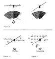
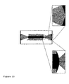
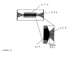
- the loudspeaker shown in figure 5 in accordance with the invention includes a direct driven rotor, that is the rotor is arranged directly on the motor axle of a motor.
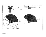
- the loudspeaker rotor has in this example three wings 2, which in their inner ends are pivotable arranged in a hub 3.
- the wings are pivotable around essentially radial pivot axles 4.
- the hub 3 is rotated by the motor 1.
- Each wing in this example has an area corresponding to approximately one third of a circle ring and is in the inner end at a distance from the pivot bering via an arm 7 connected to a coil axially moveable relative the rotor so that a an axial movement of the coil 5 pivots the wings.
- the coil 5 is surrounded by a fixed permanent magnet 6 and is fed with electricity against the influence of restraining springs so that it is moved forwards or backwards depending on the direction of electrical current.
- the pivot axles of the wings are situated slightly in front of the pressure center (approximately the center of gravity of the wing area) so that the wings moves towards a center position without driving of the air when the coil is not fed with electric current.
- the required forces for the pivoting of the wings around the pivot axles of these become very small. This condition can either be used for sound amplifying alternatively to compensate a possible week coupling, caused by the construction, between magnets and coil in the wing manoeuvering.
- the device according to the invention can principally generate sounds of arbitrary low frequency.
- the wings of the loudspeaker rotor should not be to heavy.
- the loudspeaker element in accordance with the invention can be arranged together with loudspeaker elements of conventional type in order to achieve a sufficient frequency range.
- the manoeuvering of the loudspeaker rotor can be designed in different ways as to the journaling of the wings.
- the manoeuvering can be electromagnetic with one or several magnets fixed to the wings or these may be magnetic in themselves in order to be influenced by a fixed coil.
- a coil arranged in the rotor may mechanically influence the wings when the current through the coil is altered and this is located in a fixed magnetic field generated by a fixed permanent magnet.
- Each wing may be provided with one or several coils as alternative.
- One may also consider to control the wings via a piston or coil placed in the center of the rotor where the inner part of the wing has a mechanical coupling to the piston or coil.
- the fastening of the wings and journaling thereof can be achieved in different ways and one can for instance consider the loudspeaker rotor being made of thin iron panel that has been punched, embossed and magnetized, and surrounded by one or several fixed coils. Within the concept of the invention one can also consider to use other physical phenomena to achieve the required pivoting/bending of the wings of the rotor, as for instance piezoelectric elements.
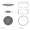
- the loudspeaker rotor need not necessarily be flat or propeller like as above but one can also consider to use a drumlike device with blades adjustable to their angles.
- the loudspeaker rotor in accordance with the invention is in much similar to a fan why one can further consider using it for the transportation of air for ventilation purposes. This can be done by instead of varying the pitch of the wings giving these a constant pitch (for the time that ventilation is desired). The loudspeaker rotor then only serves as a fan. If one instead choose to allow the pitch to vary with intended sound signals, but not around the center position where the rotor does not transport any air but around a position with a certain pitch fan and loudspeaker function is obtained at the same time.
- the loud speaker element in accordance with the invention can also be arranged in a ventilation outlet by journaling the wings freely moveable with the journaling axle somewhat in front of the pressure center, and with electromagnetic pitch control. This can for instance be done by providing the wings at their outer edges with magnets with circumferential extension. Outside a coil is placed around loud speaker rotor. With an increasing amount of air that is pushed through the loudspeaker rotor by the ventilation system the wings of the rotor will deflect from their middle position, the electromechanically enforced additional angling of the wings will oscillate around the ventilation angling so that the sound is generated independent of the ventilation.
- By the integration with the ventilation system automatically a discrete mounting is obtained and large parts corresponding to loudspeaker boxes (in the shape of the air conduits) which reduces the distortion of the sound. In particular in cars this may mean a considerable improvement of the sound quality.
- the motor is coupled directly to the loud speaker rotor, but if so desired one can also consider belt drive. Either with one rotor per motor or several rotors that are in common driven bye one motor. Also several loudspeakers rotors may be arranged on one and the same axle to increase the acoustic driveability.
- the wing pitch may in a corresponding way be controlled in common or individually for several rotors.
- the loud speaker rotors may further be driven by power net connected motors while the wing angle is controlled by signals from sound amplifiers. At this the need for powerful amplifiers as well as thick and low-ohmic connections between amplifier and bass loudspeakers is reduced.
- loudspeakers in accordance with the invention can let through an air flow the wind resistance at outdoor locations is reduced, this counter acts the pressure variations that otherwise arise. A more natural sound with better sound quality can therefor be achieved outdoors.
- infrasounds In addition to generate audible sound loudspeakers in accordance with the invention be used to generate infrasounds. In this way it becomes possible to anhilate existing infrasounds which has previously been a problem especially in view of infrasound being able to result in nausea, headache and cause drivers to fall a sleep.
- the wings alter their inclination according to the flow so that the resistance become as small as possible and one can by recording the varying pitch of the wings for instance by connecting the coil to a measuring instrument alternatively optically register the wing pitch so that a "loudspeaker rotor" instead may function as a microphone in particular for low frequencies even if a superimposed constant air flow is present.
- a "loudspeaker rotor" instead may function as a microphone in particular for low frequencies even if a superimposed constant air flow is present.
- the wings work with a constant pitch corresponding to the constant flow. Around this zero position the wings pivot at the detection of sound or flow variations.
- the microphone in accordance with invention has the advantage that it already before the detection separates the constant flow component from the varying one which reduces the noise in the measured sound. If so is desired the average flow may be detected by noting the mean pivoting of the wing pitch.
- the rotor is driven at a constant speed or at least with monitored or controlled rpm since the rotor speed has a large influence on the generated sound amplitude and the instant sound power.
- the motor can also be provided with active control where a speed control compensate the speed variations that load variations may generate.
- angle detection can then be implemented with optical/piezoelectrical or electromechanical sensors.
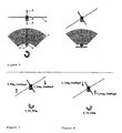
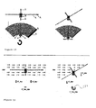
- the balance elements have the shape of arms perpendicular to the surface of the blade fastened for instance in the inner ends of the wing axles provided with weights in their outer ends. These weights will as the wing tips move perpendicularly in relation to the pivot axles of the wings. Through the perpendicular arrangement these weights will at a pivoting of the wing move radially outward in relation to the rotor axle.
- centrifugal forces figure 8
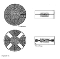
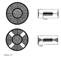
- the hub of the rotor is made with a rotational symmetric sealing surface and a corresponding shaping of the inner edges of the wings to achieve a sealed condition ( figure 23 ).
- a spherical sealing surface on the hub with the center on the rotation axle of the rotor and with a correspondingly curved inner edge of the wing, at which the center of the spherical surface lies on the pivot axle.
- the hub in its entirety can be rotationally symmetric. Since there is no mutual rotation at the inner edges but only pivoting the seal may here be established in some other way, for instance with a below like device ( figure 24 ). ( figures 19, 20 , 21 , 22 , 23 , 24 )
- a loudspeaker comprising a rotating loudspeaker element in accordance with the invention arranged in a box.
- the loudspeaker box is not entirely closed but via a flow brake or restriction connected to the surrounding.
- the risk is eliminated of the rotor being subjected to stall, that is that air transport stops entirely despite the rotation of the rotor.
- the resistance against the flow can be adapted so that it becomes frequency dependent so that optimum flow through the rotor is optimized dependent on frequency. In this way generated pressure can be optimized, stall avoided as well as acoustic short circuiting where inhalation of the pressure wave takes place.
- the invention can be used at all types of elements that with a rotating movement can transport air (or liquid), that is also radial fans, tangential fans, turbines et cetera in turbines one may advantageously by integration of the technique use the technique in the turbine steps. In many situations disturbing sound is generated by rotating air transporting elements and by means of the invention one may consider to reduce these either by the arranging of an extra rotor propeller et cetera or by controlling the rotating element that generate the sound, this in particular since these sounds often are continues.
Landscapes
- Engineering & Computer Science (AREA)
- Mechanical Engineering (AREA)
- General Engineering & Computer Science (AREA)
- Acoustics & Sound (AREA)
- Signal Processing (AREA)
- Physics & Mathematics (AREA)
- Health & Medical Sciences (AREA)
- Otolaryngology (AREA)
- Electrostatic, Electromagnetic, Magneto- Strictive, And Variable-Resistance Transducers (AREA)
- Structures Of Non-Positive Displacement Pumps (AREA)
- Surgical Instruments (AREA)
- Chair Legs, Seat Parts, And Backrests (AREA)
- Liquid Crystal (AREA)
- Measuring Volume Flow (AREA)
- Diaphragms For Electromechanical Transducers (AREA)
- Bidet-Like Cleaning Device And Other Flush Toilet Accessories (AREA)
Applications Claiming Priority (2)
| Application Number | Priority Date | Filing Date | Title |
|---|---|---|---|
| SE0401040A SE527582C2 (sv) | 2004-04-23 | 2004-04-23 | Kombinerad fläkt och högtalare |
| PCT/SE2005/000579 WO2005104617A1 (en) | 2004-04-23 | 2005-04-22 | Acoustic element |
Publications (2)
| Publication Number | Publication Date |
|---|---|
| EP1752016A1 EP1752016A1 (en) | 2007-02-14 |
| EP1752016B1 true EP1752016B1 (en) | 2010-02-10 |
Family
ID=32322641
Family Applications (1)
| Application Number | Title | Priority Date | Filing Date |
|---|---|---|---|
| EP05736173A Active EP1752016B1 (en) | 2004-04-23 | 2005-04-22 | Acoustic element |
Country Status (9)
| Country | Link |
|---|---|
| US (2) | US20070230720A1 (ja) |
| EP (1) | EP1752016B1 (ja) |
| JP (1) | JP5080242B2 (ja) |
| CN (1) | CN1973575B (ja) |
| AT (1) | ATE457604T1 (ja) |
| DE (1) | DE602005019286D1 (ja) |
| ES (1) | ES2340778T3 (ja) |
| SE (1) | SE527582C2 (ja) |
| WO (1) | WO2005104617A1 (ja) |
Families Citing this family (8)
| Publication number | Priority date | Publication date | Assignee | Title |
|---|---|---|---|---|
| KR101142134B1 (ko) * | 2010-05-27 | 2012-05-10 | 주식회사 에이알티엑스 | 스피커 구동 방법 |
| US8804986B2 (en) * | 2010-10-13 | 2014-08-12 | Aliphcom | Acoustic transducer including airfoil for generating sound |
| CN104976159B (zh) | 2014-04-11 | 2019-11-01 | 中强光电股份有限公司 | 鼓风机及涡流噪音降低方法 |
| US9800980B2 (en) | 2015-09-14 | 2017-10-24 | Wing Acoustics Limited | Hinge systems for audio transducers and audio transducers or devices incorporating the same |
| EP3350659B1 (en) | 2015-09-16 | 2023-11-22 | SZ DJI Technology Co., Ltd. | System, apparatus and method for generating sound |
| WO2018167538A1 (en) | 2017-03-15 | 2018-09-20 | Wing Acoustics Limited | Improvements in or relating to audio systems |
| WO2018172944A1 (en) | 2017-03-22 | 2018-09-27 | Wing Acoustics Limited | Systems methods and devices relating to hinges and audio transducers |
| JP2021534703A (ja) | 2018-08-14 | 2021-12-09 | ウィング アコースティックス リミテッド | オーディオトランスデューサに関するシステム、方法、およびデバイス |
Family Cites Families (20)
| Publication number | Priority date | Publication date | Assignee | Title |
|---|---|---|---|---|
| US2304022A (en) * | 1940-11-30 | 1942-12-01 | Rca Corp | Sound reproducing apparatus |
| US2394022A (en) | 1944-04-07 | 1946-02-05 | Apco Mossberg Company | Torque screw driver |
| US3058541A (en) * | 1956-07-09 | 1962-10-16 | Donald J Leslie | Rotary electrostatic speaker |
| US3695385A (en) * | 1971-05-26 | 1972-10-03 | Columbia Broadcasting Syst Inc | Variable distance doppler generator |
| USRE31667E (en) * | 1978-08-07 | 1984-09-11 | Low cost electromechanical electronic simulation circuits | |
| US4198880A (en) * | 1978-09-21 | 1980-04-22 | Leslie Donald J | Rotor drive for pulsato apparatus |
| JPS58141817A (ja) | 1982-02-18 | 1983-08-23 | Toyota Motor Corp | プレス方法 |
| JPS58141817U (ja) * | 1982-02-19 | 1983-09-24 | トキコ株式会社 | タ−ビン式流量計 |
| JPS6214598A (ja) * | 1985-07-12 | 1987-01-23 | Taisei Denki Kogyo:Kk | スピ−カ及びその製造法 |
| JPH02287217A (ja) * | 1989-04-28 | 1990-11-27 | Matsushita Electric Ind Co Ltd | 流量検出器 |
| US5191618A (en) * | 1990-12-20 | 1993-03-02 | Hisey Bradner L | Rotary low-frequency sound reproducing apparatus and method |
| US6195982B1 (en) * | 1998-12-30 | 2001-03-06 | United Technologies Corporation | Apparatus and method of active flutter control |
| JP2002101495A (ja) * | 2000-09-21 | 2002-04-05 | Citizen Electronics Co Ltd | 多機能型音響装置 |
| JP2002159916A (ja) * | 2000-11-24 | 2002-06-04 | Citizen Electronics Co Ltd | 多機能型音響装置 |
| KR200287504Y1 (ko) * | 2002-05-21 | 2002-09-05 | 주식회사 삼부커뮤닉스 | 직류 모터 내장형 스피커 |
| JP3880493B2 (ja) * | 2002-09-18 | 2007-02-14 | キヤノン株式会社 | スピーカシステム、能動式室内低音残響制御方式 |
| JP4412495B2 (ja) * | 2002-09-26 | 2010-02-10 | セイコーエプソン株式会社 | 駆動機構 |
| US8804986B2 (en) * | 2010-10-13 | 2014-08-12 | Aliphcom | Acoustic transducer including airfoil for generating sound |
| US8965024B2 (en) * | 2012-11-20 | 2015-02-24 | Doug Graham | Compact low frequency audio transducer |
| US9363611B2 (en) * | 2014-10-16 | 2016-06-07 | F. Bruce Thigpen | Rotary transducer with improved high frequency output |
-
2004
- 2004-04-23 SE SE0401040A patent/SE527582C2/sv unknown
-
2005
- 2005-04-22 EP EP05736173A patent/EP1752016B1/en active Active
- 2005-04-22 CN CN2005800127514A patent/CN1973575B/zh active Active
- 2005-04-22 JP JP2007509423A patent/JP5080242B2/ja active Active
- 2005-04-22 ES ES05736173T patent/ES2340778T3/es active Active
- 2005-04-22 WO PCT/SE2005/000579 patent/WO2005104617A1/en active Application Filing
- 2005-04-22 DE DE602005019286T patent/DE602005019286D1/de active Active
- 2005-04-22 US US11/568,179 patent/US20070230720A1/en not_active Abandoned
- 2005-04-22 AT AT05736173T patent/ATE457604T1/de not_active IP Right Cessation
-
2013
- 2013-08-29 US US14/014,139 patent/US9654862B2/en active Active
Also Published As
| Publication number | Publication date |
|---|---|
| ES2340778T3 (es) | 2010-06-09 |
| ATE457604T1 (de) | 2010-02-15 |
| CN1973575B (zh) | 2011-07-06 |
| SE527582C2 (sv) | 2006-04-18 |
| SE0401040D0 (sv) | 2004-04-23 |
| US9654862B2 (en) | 2017-05-16 |
| US20070230720A1 (en) | 2007-10-04 |
| US20140003624A1 (en) | 2014-01-02 |
| JP5080242B2 (ja) | 2012-11-21 |
| WO2005104617A1 (en) | 2005-11-03 |
| EP1752016A1 (en) | 2007-02-14 |
| CN1973575A (zh) | 2007-05-30 |
| DE602005019286D1 (de) | 2010-03-25 |
| SE0401040L (sv) | 2005-10-24 |
| JP2007534268A (ja) | 2007-11-22 |
Similar Documents
| Publication | Publication Date | Title |
|---|---|---|
| US9654862B2 (en) | Acoustic element | |
| US5191618A (en) | Rotary low-frequency sound reproducing apparatus and method | |
| US5636287A (en) | Apparatus and method for the active control of air moving device noise | |
| CA1199875A (en) | Subwoofer speaker system | |
| US20160286304A1 (en) | Acoustic transducer including airfoil for generating sound | |
| EP2930373B1 (en) | Blower and method for decreasing eddy noise | |
| JP3407141B2 (ja) | 低騒音機器 | |
| KR20020007299A (ko) | 펌프 액츄에이터를 구비한 사운드 발생기 | |
| US6851930B2 (en) | Noise reduction in an air moving apparatus | |
| EP3033655B1 (en) | Systems and methods for control of infrasound pressures | |
| US6133656A (en) | Brushless commutated torque motor for use with a rotary low frequency sound reproducing apparatus | |
| JP2005098272A (ja) | 遠心ファン | |
| JPS6253099A (ja) | ロ−タリ型スピ−カ | |
| JPH10169599A (ja) | ファン装置 | |
| US7085392B1 (en) | Loudspeaker sound modulation appliance | |
| KR20190083592A (ko) | 소리 발생 및 날개 피치 가변이 가능한 팬 | |
| JP3965432B2 (ja) | 直接変調型気流スピーカ及びスピーカユニット | |
| JPS61157000A (ja) | スピ−カ | |
| JP2735291C (ja) |
Legal Events
| Date | Code | Title | Description |
|---|---|---|---|
| PUAI | Public reference made under article 153(3) epc to a published international application that has entered the european phase |
Free format text: ORIGINAL CODE: 0009012 |
|
| 17P | Request for examination filed |
Effective date: 20061123 |
|
| AK | Designated contracting states |
Kind code of ref document: A1 Designated state(s): AT BE BG CH CY CZ DE DK EE ES FI FR GB GR HU IE IS IT LI LT LU MC NL PL PT RO SE SI SK TR |
|
| DAX | Request for extension of the european patent (deleted) | ||
| 17Q | First examination report despatched |
Effective date: 20090513 |
|
| GRAP | Despatch of communication of intention to grant a patent |
Free format text: ORIGINAL CODE: EPIDOSNIGR1 |
|
| GRAS | Grant fee paid |
Free format text: ORIGINAL CODE: EPIDOSNIGR3 |
|
| GRAA | (expected) grant |
Free format text: ORIGINAL CODE: 0009210 |
|
| AK | Designated contracting states |
Kind code of ref document: B1 Designated state(s): AT BE BG CH CY CZ DE DK EE ES FI FR GB GR HU IE IS IT LI LT LU MC NL PL PT RO SE SI SK TR |
|
| REG | Reference to a national code |
Ref country code: GB Ref legal event code: FG4D |
|
| REG | Reference to a national code |
Ref country code: CH Ref legal event code: EP |
|
| REG | Reference to a national code |
Ref country code: IE Ref legal event code: FG4D |
|
| REF | Corresponds to: |
Ref document number: 602005019286 Country of ref document: DE Date of ref document: 20100325 Kind code of ref document: P |
|
| REG | Reference to a national code |
Ref country code: NL Ref legal event code: T3 |
|
| REG | Reference to a national code |
Ref country code: ES Ref legal event code: FG2A Ref document number: 2340778 Country of ref document: ES Kind code of ref document: T3 |
|
| LTIE | Lt: invalidation of european patent or patent extension |
Effective date: 20100210 |
|
| PG25 | Lapsed in a contracting state [announced via postgrant information from national office to epo] |
Ref country code: IS Free format text: LAPSE BECAUSE OF FAILURE TO SUBMIT A TRANSLATION OF THE DESCRIPTION OR TO PAY THE FEE WITHIN THE PRESCRIBED TIME-LIMIT Effective date: 20100610 Ref country code: PT Free format text: LAPSE BECAUSE OF FAILURE TO SUBMIT A TRANSLATION OF THE DESCRIPTION OR TO PAY THE FEE WITHIN THE PRESCRIBED TIME-LIMIT Effective date: 20100611 Ref country code: LT Free format text: LAPSE BECAUSE OF FAILURE TO SUBMIT A TRANSLATION OF THE DESCRIPTION OR TO PAY THE FEE WITHIN THE PRESCRIBED TIME-LIMIT Effective date: 20100210 |
|
| PG25 | Lapsed in a contracting state [announced via postgrant information from national office to epo] |
Ref country code: PL Free format text: LAPSE BECAUSE OF FAILURE TO SUBMIT A TRANSLATION OF THE DESCRIPTION OR TO PAY THE FEE WITHIN THE PRESCRIBED TIME-LIMIT Effective date: 20100210 Ref country code: SI Free format text: LAPSE BECAUSE OF FAILURE TO SUBMIT A TRANSLATION OF THE DESCRIPTION OR TO PAY THE FEE WITHIN THE PRESCRIBED TIME-LIMIT Effective date: 20100210 Ref country code: FI Free format text: LAPSE BECAUSE OF FAILURE TO SUBMIT A TRANSLATION OF THE DESCRIPTION OR TO PAY THE FEE WITHIN THE PRESCRIBED TIME-LIMIT Effective date: 20100210 Ref country code: AT Free format text: LAPSE BECAUSE OF FAILURE TO SUBMIT A TRANSLATION OF THE DESCRIPTION OR TO PAY THE FEE WITHIN THE PRESCRIBED TIME-LIMIT Effective date: 20100210 |
|
| PG25 | Lapsed in a contracting state [announced via postgrant information from national office to epo] |
Ref country code: CY Free format text: LAPSE BECAUSE OF FAILURE TO SUBMIT A TRANSLATION OF THE DESCRIPTION OR TO PAY THE FEE WITHIN THE PRESCRIBED TIME-LIMIT Effective date: 20100210 Ref country code: EE Free format text: LAPSE BECAUSE OF FAILURE TO SUBMIT A TRANSLATION OF THE DESCRIPTION OR TO PAY THE FEE WITHIN THE PRESCRIBED TIME-LIMIT Effective date: 20100210 Ref country code: RO Free format text: LAPSE BECAUSE OF FAILURE TO SUBMIT A TRANSLATION OF THE DESCRIPTION OR TO PAY THE FEE WITHIN THE PRESCRIBED TIME-LIMIT Effective date: 20100210 Ref country code: GR Free format text: LAPSE BECAUSE OF FAILURE TO SUBMIT A TRANSLATION OF THE DESCRIPTION OR TO PAY THE FEE WITHIN THE PRESCRIBED TIME-LIMIT Effective date: 20100511 Ref country code: BE Free format text: LAPSE BECAUSE OF FAILURE TO SUBMIT A TRANSLATION OF THE DESCRIPTION OR TO PAY THE FEE WITHIN THE PRESCRIBED TIME-LIMIT Effective date: 20100210 Ref country code: SE Free format text: LAPSE BECAUSE OF FAILURE TO SUBMIT A TRANSLATION OF THE DESCRIPTION OR TO PAY THE FEE WITHIN THE PRESCRIBED TIME-LIMIT Effective date: 20100210 |
|
| PG25 | Lapsed in a contracting state [announced via postgrant information from national office to epo] |
Ref country code: CZ Free format text: LAPSE BECAUSE OF FAILURE TO SUBMIT A TRANSLATION OF THE DESCRIPTION OR TO PAY THE FEE WITHIN THE PRESCRIBED TIME-LIMIT Effective date: 20100210 Ref country code: MC Free format text: LAPSE BECAUSE OF NON-PAYMENT OF DUE FEES Effective date: 20100430 Ref country code: SK Free format text: LAPSE BECAUSE OF FAILURE TO SUBMIT A TRANSLATION OF THE DESCRIPTION OR TO PAY THE FEE WITHIN THE PRESCRIBED TIME-LIMIT Effective date: 20100210 Ref country code: BG Free format text: LAPSE BECAUSE OF FAILURE TO SUBMIT A TRANSLATION OF THE DESCRIPTION OR TO PAY THE FEE WITHIN THE PRESCRIBED TIME-LIMIT Effective date: 20100510 |
|
| PLBE | No opposition filed within time limit |
Free format text: ORIGINAL CODE: 0009261 |
|
| STAA | Information on the status of an ep patent application or granted ep patent |
Free format text: STATUS: NO OPPOSITION FILED WITHIN TIME LIMIT |
|
| 26N | No opposition filed |
Effective date: 20101111 |
|
| PG25 | Lapsed in a contracting state [announced via postgrant information from national office to epo] |
Ref country code: DK Free format text: LAPSE BECAUSE OF FAILURE TO SUBMIT A TRANSLATION OF THE DESCRIPTION OR TO PAY THE FEE WITHIN THE PRESCRIBED TIME-LIMIT Effective date: 20100210 |
|
| PG25 | Lapsed in a contracting state [announced via postgrant information from national office to epo] |
Ref country code: HU Free format text: LAPSE BECAUSE OF FAILURE TO SUBMIT A TRANSLATION OF THE DESCRIPTION OR TO PAY THE FEE WITHIN THE PRESCRIBED TIME-LIMIT Effective date: 20100811 |
|
| PG25 | Lapsed in a contracting state [announced via postgrant information from national office to epo] |
Ref country code: TR Free format text: LAPSE BECAUSE OF FAILURE TO SUBMIT A TRANSLATION OF THE DESCRIPTION OR TO PAY THE FEE WITHIN THE PRESCRIBED TIME-LIMIT Effective date: 20100210 |
|
| REG | Reference to a national code |
Ref country code: FR Ref legal event code: PLFP Year of fee payment: 12 |
|
| REG | Reference to a national code |
Ref country code: FR Ref legal event code: PLFP Year of fee payment: 13 |
|
| REG | Reference to a national code |
Ref country code: FR Ref legal event code: PLFP Year of fee payment: 14 |
|
| PGFP | Annual fee paid to national office [announced via postgrant information from national office to epo] |
Ref country code: IT Payment date: 20230426 Year of fee payment: 19 Ref country code: IE Payment date: 20230419 Year of fee payment: 19 Ref country code: FR Payment date: 20230420 Year of fee payment: 19 Ref country code: ES Payment date: 20230627 Year of fee payment: 19 Ref country code: DE Payment date: 20220620 Year of fee payment: 19 Ref country code: CH Payment date: 20230502 Year of fee payment: 19 |
|
| PGFP | Annual fee paid to national office [announced via postgrant information from national office to epo] |
Ref country code: GB Payment date: 20230419 Year of fee payment: 19 |
|
| PGFP | Annual fee paid to national office [announced via postgrant information from national office to epo] |
Ref country code: LU Payment date: 20240418 Year of fee payment: 20 |
|
| PGFP | Annual fee paid to national office [announced via postgrant information from national office to epo] |
Ref country code: NL Payment date: 20240418 Year of fee payment: 20 |