EP1750145A2 - Radarsysteme und Verfahren unter Verwendung verschränkter Quantenteilchen - Google Patents
Radarsysteme und Verfahren unter Verwendung verschränkter Quantenteilchen Download PDFInfo
- Publication number
- EP1750145A2 EP1750145A2 EP06254079A EP06254079A EP1750145A2 EP 1750145 A2 EP1750145 A2 EP 1750145A2 EP 06254079 A EP06254079 A EP 06254079A EP 06254079 A EP06254079 A EP 06254079A EP 1750145 A2 EP1750145 A2 EP 1750145A2
- Authority
- EP
- European Patent Office
- Prior art keywords
- signal
- entangled
- target
- photons
- frequency
- Prior art date
- Legal status (The legal status is an assumption and is not a legal conclusion. Google has not performed a legal analysis and makes no representation as to the accuracy of the status listed.)
- Granted
Links
- 239000002245 particle Substances 0.000 title claims abstract description 39
- 238000000034 method Methods 0.000 title claims description 37
- 239000002096 quantum dot Substances 0.000 claims description 24
- 238000011895 specific detection Methods 0.000 claims description 9
- 230000003993 interaction Effects 0.000 claims description 6
- 238000001514 detection method Methods 0.000 claims description 4
- 239000000203 mixture Substances 0.000 claims description 4
- 230000003247 decreasing effect Effects 0.000 claims 1
- 230000003746 surface roughness Effects 0.000 claims 1
- 239000013077 target material Substances 0.000 claims 1
- 230000008569 process Effects 0.000 description 18
- 238000010586 diagram Methods 0.000 description 16
- 230000007704 transition Effects 0.000 description 7
- 238000010521 absorption reaction Methods 0.000 description 4
- 230000000875 corresponding effect Effects 0.000 description 4
- 239000000463 material Substances 0.000 description 4
- 230000010287 polarization Effects 0.000 description 4
- 230000005699 Stark effect Effects 0.000 description 3
- 239000011358 absorbing material Substances 0.000 description 3
- 230000008878 coupling Effects 0.000 description 3
- 238000010168 coupling process Methods 0.000 description 3
- 238000005859 coupling reaction Methods 0.000 description 3
- 239000013078 crystal Substances 0.000 description 3
- 230000006870 function Effects 0.000 description 3
- 229910052751 metal Inorganic materials 0.000 description 3
- 239000002184 metal Substances 0.000 description 3
- 230000000149 penetrating effect Effects 0.000 description 3
- 238000012545 processing Methods 0.000 description 3
- XLYOFNOQVPJJNP-UHFFFAOYSA-N water Substances O XLYOFNOQVPJJNP-UHFFFAOYSA-N 0.000 description 3
- 230000008901 benefit Effects 0.000 description 2
- 230000006835 compression Effects 0.000 description 2
- 238000007906 compression Methods 0.000 description 2
- 230000005684 electric field Effects 0.000 description 2
- 238000010191 image analysis Methods 0.000 description 2
- 238000003384 imaging method Methods 0.000 description 2
- 230000004048 modification Effects 0.000 description 2
- 238000012986 modification Methods 0.000 description 2
- 230000003287 optical effect Effects 0.000 description 2
- 230000000644 propagated effect Effects 0.000 description 2
- 230000005855 radiation Effects 0.000 description 2
- 230000003595 spectral effect Effects 0.000 description 2
- 238000010183 spectrum analysis Methods 0.000 description 2
- 241000931526 Acer campestre Species 0.000 description 1
- 241000238366 Cephalopoda Species 0.000 description 1
- 238000001069 Raman spectroscopy Methods 0.000 description 1
- 238000000862 absorption spectrum Methods 0.000 description 1
- 238000007792 addition Methods 0.000 description 1
- 238000004458 analytical method Methods 0.000 description 1
- 238000003491 array Methods 0.000 description 1
- 239000004566 building material Substances 0.000 description 1
- 230000008859 change Effects 0.000 description 1
- 230000001427 coherent effect Effects 0.000 description 1
- 239000002131 composite material Substances 0.000 description 1
- 230000003750 conditioning effect Effects 0.000 description 1
- 239000004020 conductor Substances 0.000 description 1
- 230000001276 controlling effect Effects 0.000 description 1
- 230000002596 correlated effect Effects 0.000 description 1
- 238000007405 data analysis Methods 0.000 description 1
- 230000003292 diminished effect Effects 0.000 description 1
- 230000003467 diminishing effect Effects 0.000 description 1
- 230000000694 effects Effects 0.000 description 1
- 230000005670 electromagnetic radiation Effects 0.000 description 1
- 238000005516 engineering process Methods 0.000 description 1
- 230000005283 ground state Effects 0.000 description 1
- 230000006872 improvement Effects 0.000 description 1
- 238000005259 measurement Methods 0.000 description 1
- 230000010355 oscillation Effects 0.000 description 1
- 238000003909 pattern recognition Methods 0.000 description 1
- 230000001902 propagating effect Effects 0.000 description 1
- 230000005610 quantum mechanics Effects 0.000 description 1
- 238000012552 review Methods 0.000 description 1
- 239000004065 semiconductor Substances 0.000 description 1
- 238000007493 shaping process Methods 0.000 description 1
- 230000003068 static effect Effects 0.000 description 1
- 230000008685 targeting Effects 0.000 description 1
- 230000009466 transformation Effects 0.000 description 1
- 238000000844 transformation Methods 0.000 description 1
- WFKWXMTUELFFGS-UHFFFAOYSA-N tungsten Chemical compound [W] WFKWXMTUELFFGS-UHFFFAOYSA-N 0.000 description 1
- 229910052721 tungsten Inorganic materials 0.000 description 1
- 239000010937 tungsten Substances 0.000 description 1
- 230000005641 tunneling Effects 0.000 description 1
- 230000004304 visual acuity Effects 0.000 description 1
- 230000005428 wave function Effects 0.000 description 1
Images


Classifications
-
- G—PHYSICS
- G01—MEASURING; TESTING
- G01S—RADIO DIRECTION-FINDING; RADIO NAVIGATION; DETERMINING DISTANCE OR VELOCITY BY USE OF RADIO WAVES; LOCATING OR PRESENCE-DETECTING BY USE OF THE REFLECTION OR RERADIATION OF RADIO WAVES; ANALOGOUS ARRANGEMENTS USING OTHER WAVES
- G01S13/00—Systems using the reflection or reradiation of radio waves, e.g. radar systems; Analogous systems using reflection or reradiation of waves whose nature or wavelength is irrelevant or unspecified
- G01S13/02—Systems using reflection of radio waves, e.g. primary radar systems; Analogous systems
-
- G—PHYSICS
- G01—MEASURING; TESTING
- G01S—RADIO DIRECTION-FINDING; RADIO NAVIGATION; DETERMINING DISTANCE OR VELOCITY BY USE OF RADIO WAVES; LOCATING OR PRESENCE-DETECTING BY USE OF THE REFLECTION OR RERADIATION OF RADIO WAVES; ANALOGOUS ARRANGEMENTS USING OTHER WAVES
- G01S17/00—Systems using the reflection or reradiation of electromagnetic waves other than radio waves, e.g. lidar systems
- G01S17/02—Systems using the reflection of electromagnetic waves other than radio waves
-
- G—PHYSICS
- G01—MEASURING; TESTING
- G01S—RADIO DIRECTION-FINDING; RADIO NAVIGATION; DETERMINING DISTANCE OR VELOCITY BY USE OF RADIO WAVES; LOCATING OR PRESENCE-DETECTING BY USE OF THE REFLECTION OR RERADIATION OF RADIO WAVES; ANALOGOUS ARRANGEMENTS USING OTHER WAVES
- G01S7/00—Details of systems according to groups G01S13/00, G01S15/00, G01S17/00
- G01S7/02—Details of systems according to groups G01S13/00, G01S15/00, G01S17/00 of systems according to group G01S13/00
- G01S7/41—Details of systems according to groups G01S13/00, G01S15/00, G01S17/00 of systems according to group G01S13/00 using analysis of echo signal for target characterisation; Target signature; Target cross-section
-
- G—PHYSICS
- G01—MEASURING; TESTING
- G01S—RADIO DIRECTION-FINDING; RADIO NAVIGATION; DETERMINING DISTANCE OR VELOCITY BY USE OF RADIO WAVES; LOCATING OR PRESENCE-DETECTING BY USE OF THE REFLECTION OR RERADIATION OF RADIO WAVES; ANALOGOUS ARRANGEMENTS USING OTHER WAVES
- G01S7/00—Details of systems according to groups G01S13/00, G01S15/00, G01S17/00
- G01S7/48—Details of systems according to groups G01S13/00, G01S15/00, G01S17/00 of systems according to group G01S17/00
- G01S7/4802—Details of systems according to groups G01S13/00, G01S15/00, G01S17/00 of systems according to group G01S17/00 using analysis of echo signal for target characterisation; Target signature; Target cross-section
Definitions
- the "Rayleigh diffraction limit”, which is the spatial resolution with which an object can be detected, is limited by the wavelength of the radiation used for detection. Higher frequencies are therefore required to resolve smaller objects.
- Microwaves of high frequency are absorbed in the atmosphere at rates exponentially higher than microwaves of low frequency. Accordingly, low frequency radar is preferred for longer range.
- the ability to distinguish two objects adjacent to each other referred to as "resolving power”
- resolving power is proportional to the ratio of wave length to aperture.
- radar can only distinguish an object if the wavelength of the electromagnetic radiation is the same or smaller than the object.
- the Rayleigh diffraction limit combined with the earth atmosphere's attenuation profile forces radar designers to choose between long range at low resolution, or short range at high resolution.
- penetrating radars such as foliage penetrating radar (FOPEN) or ground penetrating radar (GPR) require low frequencies to minimize attenuation within the penetrated medium. Consequently, only the very largest objects can be resolved, diminishing the utility of such radar systems.
- FOPEN foliage penetrating radar
- GPR ground penetrating radar
- a quantum system may exist in several states simultaneously corresponding to different values of a physical observable such as position, momentum, or spin. Changes among properties of entangled photons are correlated.
- the composite system is described by a nonseparable state, that is, a superposition of substates describing eigenstates of the specific observables. Each of these substates corresponds to eigenvalues of some set of observables (e.g., particles' positions).
- An entangled state can thus be put in different forms, each being adapted to the analysis of a specific detection procedure.
- quantum states of two or more particles are described with reference to each other, even though the individual objects may be spatially separated.
- an entangled quantum particle generator generates a signal including a plurality of entangled particles.
- the wavelength of the signal is the sum of the wavelengths of the entangled particles.
- a signal processor determines a characteristic of the target based on information derived from at least some of the entangled particles in the return signal.
- the frequency of the signal is selected to propagate the signal through a medium and the frequencies of the entangled particles are selected to provide sufficient data in the return signal to resolve the characteristic of the target.
- Other embodiments include generating entangled photons, transmitting the entangled photons in a radio-frequency signal.
- the frequency of the signal is selected to propagate through a particular medium and the number of the entangled photons is determined by the desired resolution of the return signal. At least a portion of the entangled photons reflected by a target are detected.
- Embodiments of systems and methods for radar systems using entangled quantum particles are disclosed herein.
- Entangled beams allow the absorption spectrum and the resolution limit of quantum radar systems to be selected independently of one another.
- quantum radar systems can simultaneously achieve the low attenuation/high range associated with a long wave length and the high resolution associated with a short wave length.
- the wavelength of a two or more entangled particle is proportional to the number of entangled particles associated with the multiparticle. For example, the wavelength of a pair of entangled photons is twice that of the single photon. The wavelength of three entangled photons is three times that of the single photon. For a foursome, the difference is a multiple of 4, and so on.
- S/N signal to noise
- Waves traveling at certain frequencies are absorbed in a medium when the wavelength of propagating photons is resonant with molecules in the medium, such as water molecules in air.
- Classical radar systems are typically limited to microwave frequencies due to absorption, leaving the far-infrared frequencies largely unused. Entangling photons into a multiphoton changes their resonance behavior and "detunes" them with respect to the absorption bands. Entangled radar waves can combine one or more particles with a relatively high frequency for resolution with one or more particles at a lower frequency for more effective propagation through various absorption bands in the atmosphere or other medium.
- the frequencies of the waves for propagation and resolution can be separately controlled, allowing the quantum radar system to use signals for resolution at previously unused frequencies.
- quantum radar is capable of providing information about targets that cannot be provided using classical radar systems.
- return signal energy is proportional to the density of radiation power emanating from the antenna (P avg ), sprectral cross-section of the target ( ⁇ ), area of aperture (A eqv ) (assuming receive and transmit antennas are the same size), and time on target (t tot ); and is inversely proportional to the distance to the target (R), the wavelength of the signal ( ⁇ ), and a loss factor (L), as shown by the following equation:
- Signal Energy P avg ⁇ A eqv 2 ⁇ ⁇ ⁇ t tot 4 ⁇ ⁇ ⁇ R 4 ⁇ ⁇ 2 ⁇ L
- E ef denote the energy per entangled photon of frequency ⁇ ef
- N efPmf the number of entangled photons per multiphoton
- N mf the number of multiphotons per second.
- the signal energy of a radar system using entangled quantum particles is proportional to the cube of the number of entanglement photons per multiphoton.
- the effective wavelength ⁇ ef is inversely proportional to the number of entangled photons in a multiphoton.
- the return signals from the individual (entangled photons) photons can be used to achieve high target resolution while the wavelength of the multiphoton can be designed for effective propagation through the subject medium.
- Range resolution in conventional radar systems is inversely proportional to the pulse width of the waveform generator signal.
- Pulse compression One technique to improve resolution despite the Rayleigh limit is referred to as "pulse compression," which compresses a long pulse temporally while maintaining the total energy of the pulse. Increased resolution is achieved at a cost of less image data per unit time.
- Another technique to improve resolution despite the Rayleigh limit includes increasing the length scale of the aperture by using travel distance over a period of time to create a "synthetic" aperture.
- Synthetic Aperture Radar (SAR) systems increase resolution at the cost of extending the time required to collect an image. As a result, a reduced number of images can be collected in a given interval.
- a quantum radar system can focus more energy on the target per unit of aperture per unit time and extract more information than a comparable classical radar system.
- One limitation in classical radar systems is that the ratio of imaging rate to resolution is fixed such that searching for and tracking targets cannot be accomplished simultaneously.
- Different radar systems, or complex radar systems capable of operating in interleaved modes are required to detect ground and air moving targets.
- the imaging rate to resolution ratio can be selected for simultaneous targeting, tracking, and even weapon guidance purposes.
- multiphotons in multiple frequency ranges can be generated dynamically to propagate through different mediums and resolve different types of targets.
- FIG. 1 a diagram of an embodiment of quantum radar system 100 is shown including transmitter section 102 with entangled particle waveform generator 104 and downconverter 105 that emits radar beams comprising entangled multiphoton waveforms.
- signals are both transmitted and received via a single antenna 106.
- duplexer 108 switches to provide the output of waveform generator 104 to antenna 106 during transmit mode.
- different antennas 106 can be used for transmit and receive functions.
- Receiver section 110 typically includes detector 112, signal quality processor 116, and signal/data processor 120.
- the radar data generated by processor 120 as images and/or other suitable format can be provided to display 122 as well as other output devices such as a printer or storage media.
- Waveform generator 104 and signal/data processor 120 interface with controller 124. Controller 124 can provide signals to positioning system 130, which adjusts the direction in which radar beams are transmitted and received to provide improved information regarding a target.
- Waveform generator 104 can be configured to generate single photon and/or multiphoton waveforms using a variety of different techniques and devices such as one or more atom cavities, quantum dots, Bose-Einstein condensates as well as other suitable devices for generating entangled photons.
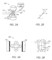
- FIG. 2A shows an embodiment of atom cavity 200 in which one or more energy beams 202 are directed to one or more atoms trapped in an enclosed cavity 206 formed by a field between two superconducting mirrors 208.
- One or more devices 210 capable of generating an energy beam 202 such as a laser, maser, ultrasonic, and/or any other type of energy beams, can be used to accelerate or decelerate electrons in atoms in cavity 206, thereby generating a signal 212 composed of multiple entangled particles.
- Controller 124 can be configured to control operation of energy beam device 210 to generate entangled particles at the frequencies desired to detect one or more characteristics of a target.
- FIG. 2B shows the relevant atomic levels e, g, and i of atoms in cavity 206.
- Atoms emitted by energy beam devices 210 are prepared in e or g atomic levels.
- the atoms cross cavity 206 resonant at frequency C on the e ⁇ g transition.
- Classical Rabi pulses at frequency S from pulse generator 214 can be applied on the atoms before and after they interact with cavity 206 to perform programmed transformations on each atomic state.
- the term Rabi pulses refers to an atom that cyclically absorbs and re-emits photons at resonance when illuminated by a coherent beam of photons.
- a static electric field applied across mirrors 208 is used to control the atomic transition frequency through the Stark effect, which refers to the shift in, and broadening of, the spectral line structure of matter in the presence of an electric field.
- the residual photon number increases at the end of the sequence.
- the position of an atom can be determined with a precision that allows each atom to be addressed independently.
- the joint atom-photon state manipulations rely on the resonant quantum Rabi rotation experienced by each atom in cavity 206.
- Atom cavity system 200 undergoes oscillations between the states
- the full effective atom cavity interaction time corresponds to a 2 ⁇ Rabi pulse. Shorter interaction times are obtained by using the Stark effect to switch the atomic transition away from cavity resonance at preset times.
- An entangled state is achieved by combining Rabi pulses of various durations on successive atoms.
- Quantum Dots are very small semiconductor structures on the order of nanometers or somewhat larger in diameter that confine electrons and holes in three spatial dimensions and to a very small number of energy levels, depending on their size.
- a QD is larger than an atom but behaves as if it were one, releasing its trapped electron-hole pair to an adjacent conductor when it captures an incident photon.
- FIG. 3A shows four quantum dots A, B, L, R, arranged between two electron reservoirs 302.
- quantum dot L is coupled to one of electron reservoirs 302 and quantum dots A and B, as discussed in Emary.
- Quantum dot R is coupled to the other electron reservoir 302 as well as quantum dots A and B. There is no direct coupling between quantum dots L and R, or A and B.
- FIG. 3B shows the positions of quantum dot levels for quantum dots A, B, L, R.
- An electron tunnels through the single level in dot L into a superposition ⁇
- the electron decays to the ground state with the emission of two photons.
- the resulting state ⁇
- Subsequent tunneling of the electron out of the lower levels into quantum dot R establishes a unique final state for the electron, thus separating the quantum dot field wave function and liberating a pair of entangled particles 304, 306.
- FIG. 3C shows another embodiment of a waveform generator 310 configured to generate multiphoton waveforms using only two dots, with dots L and R being replaced by Y-junction connections.
- the quantum dots A and B are connected to within a Fermi wavelength of each other at the Y-junctions to ensure that an electron tunnels coherently into both quantum dots A and B, as further described in Emary..
- one laser 322 can be used to trigger or generate the photons
- another laser 324 can be used to couple the emitted photons in an entangled RF wave 326.
- some embodiments can include an array 328 of quantum dots and triggering and coupling lasers 320, 322.
- a corresponding number of additional lasers 320, 322 can be used to generate more than two entangled particles.
- BECs 404 are comprised of a group of atoms that exist in exactly the same state. Methods to produce entangled states of several particles from a BEC 404 are described in " Many-Particle Entanglement With Bose-Einstein Condensates" by A. S ⁇ rensen, L.-M. Duan, J. I. Cirac & P.
- controller 124 can be configured to perform a modulating function by controlling a laser or other energy source in waveform generator 104 to transmit pulsed or continuous multiphoton waveforms. Additionally, waveform generator 104 can be controlled to vary one or more properties of successive entangled photon waveforms so that either or both the frequency and the property of interest can be detected to correlate emitted and return signals.
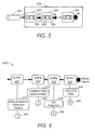
- FIG. 5 shows an embodiment of downconverter 500 configured to generate multiphoton waveforms that can be used in radar system 100 of FIG. 1.
- Waveform generator 104 generates single and/or multi entangled photon waveforms.
- the photon(s) are input to downconverter 500, which, in the embodiment shown, includes one or more doubly-resonant amplifiers (DRA) 504.
- DRA 504 increases the number of entangled photons by a factor of two while downconverting the frequencies of the photons by a factor of two.
- DRA 504 includes a cavity formed by mirrors 506 on opposite sides of a phase-matched nonlinear crystal 508.
- the photon of the incident waveform is divided into two photons, the sum energy of which is equivalent to the energy of the photon waveform from waveform generator 104 by nonlinear optical crystal 508.
- the wavelengths of the two generated photon waveforms are determined by the phase matching condition, which is changed by the angle between the incident photon waveform from waveform generator 104 and the axes of crystal 508.
- the wavelengths of the signal and the idler waveforms can, therefore, be tuned by changing the phase matching condition.
- downconverter 105 can include as many DRAs 504 as required to generate the desired number of entangled photons. Additionally, one or more switch(es) (not shown) may be included between DRAs 504 to divert the entangled photon waveforms to duplexer 108 instead of through the remaining DRAs 504, thus providing the capability to dynamically vary the number of entangled photons used. Controller 124 can be configured to operate the switch(es) based on performance and/or power requirements.
- Positioning system 130 can be operated by controller 124 in coordination with waveform generator 104 and downconverter 105 to achieve desired radar beam shapes and to focus the emitted signal in a particular direction.
- the desired radar beam shapes can be indicated by an automatically and/or manually actuated radar mode switch coupled to provide input to controller 124.
- FIG. 6 shows a diagram of an embodiment of a detector system 600 that can be used as detector 112 in radar system 100.
- the return signal is comprised of multiple entangled photons, which are separated by a series of beam splitters 602. Since measuring an attribute of an entangled photon alters the attribute, the number splitters 602 included in detector system 600 depends on the number of attributes of the entangled photons to be measured.
- photons deflected by the series of splitters 602 are input to corresponding attribute-specific detection devices 612, such as polarizing filter 604, spin detection device 608, and interferometer/spectrometer 610.
- Polarizing filter 604 indicates the polarization of the photons in the return signal and can be used to determine the direction of a radar target's velocity vector.
- Spin detection device 608 such as a Stern-Gerlach device, indicates the spin of the photons in the return signal. The level of spin can be used to determine the magnitude of the target's velocity vector.
- Measurements from interferometer/spectrometer 610 can be used to determine the phase and analyze spectral properties of the photons in the return signal. The phase angle can be used to determine azimuth and elevation of the target, as well as the Doppler shift of the return signal. Spectral analysis can be used to determine the material composition of the target.
- Other devices suitable to measure specific attributes of the photons in the return signal can be used. Such a configuration allows entangled photons to be separated and attributes to be measured independently of one another, that is, without affecting other attributes of the entangled photons.
- a photon detector 606 can be included with each attribute-specific detection device 612 to count the number of photons with the detected attribute. The detected number can be used to determine a statistical estimate of the number of photons in the return signal with that specific attribute.
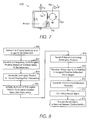
- a schematic diagram representing an example of detector 612 capable of detecting single photons is shown in FIG. 7 and described in a publication entitled " Demonstration Of A Low-Noise Near-Infrared Photon Counter With Multi-photon Discrimination," by Aaron J. Miller, Sae Woo Nam, John M. Martinis, and Alexander V. Sergienko, Applied Physics Letters, Volume 83, Number 4 (July 28, 2003 ) and incorporated by reference herein.
- Detector 606 includes a superconducting absorbing material 702 that uses transition edge sensor (TES) microcalorimeter technology to produce an electrical signal proportional to the heat produced by the absorption of a photon from the return signal.
- Absorbing material 702 can be configured as a metal film, such as tungsten, with very narrow superconducting-to-normal resistive transition characteristics. Applying a voltage across the metal film causes the film to self-bias in the resistive transition allowing its temperature to be determined by measuring the electrical current flow through the metal. The integral of the current pulse is proportional to the energy deposited in the absorbing material 702 from the photon in the return signal.
- the voltage bias for detector 606 is provided by current source ( I bias ) and a shunt resistor ( R b ).
- the detector signal I sense is amplified by one or more amplifiers 704, such as an array of SQUID amplifiers, and processed with pulse shaping electronics 706. Note that other suitable types of detectors 606 can be used.
- the information available from attribute-specific detection devices 612 can be provided to signal quality processor 116.
- Signal quality processor 116 can filter noise out of the signals, and perform other functions to condition the signals to provide the most information available to signal data processor 120.
- signal quality processor 116 can measure the fidelity of the return signal and distinguish the return signal from noise using a photonic lattice or other suitable structure.
- Signal/data processor 120 coherently combines the pulses within each return signal to obtain a sharpened image that can be presented on display 122.
- Image analysis logic can be included in signal processor 120 to determine the type of target(s) shown in the image, as well as to determine speed, direction, number, and other attributes of the target(s).
- Components in processing system 100 can be embodied in any suitable device(s) using any suitable combination of firmware, software, and/or hardware, such as microprocessors, Field Programmable Gate Arrays (FPGAs), Application Specific Integrated Circuit (ASICs), or other suitable devices.
- FPGAs Field Programmable Gate Arrays
- ASICs Application Specific Integrated Circuit
- Quantum radar system 100 may allow quantum radar system 100 to attain near zero attenuation rates in the atmosphere, and greatly diminished attenuation rates in other media including foliage, building materials, earthen layers, etc.
- Quantum radar system 100 thus, can be adapted to visualize useful target details through background and/or camouflaging clutter, through plasma shrouds around hypersonic air vehicles, through the layers of concealment hiding underground facilities, IEDs, mines, and other threats -- all while operating from an airborne platform or other suitable platform.
- Quantum radar system 100 may also improve the performance of advanced image processing and pattern recognition systems, as well as defeat most RF signature management systems when the propagation frequency is tuned to the resonant wave length of the target.
- FIG. 8 is a flow diagram of an embodiment of a process for generating a signal comprising entangled photons and receiving a return signal comprising the entangled photons reflected from a target that can be utilized in the radar system 100 of FIG. 1.
- Process 800 can include determining one or more characteristics of target(s) to be detected. The characteristics can include distance, azimuth and elevation, material composition, type of target, high/medium/low resolution images, traveling speed and direction, and other suitable characteristics.
- One or more mode selection switches can be provided for an operator to dynamically select one or more of the characteristics to be detected.
- components in radar system 100 such as controller 124 can be configured to automatically add and/or switch modes based on the operating mode(s) of other devices, such as aircraft, space platform, or other device, with which radar system 100 can be utilized.
- Process 802 can include determining wavelength/frequency for the entangled photons based on characteristic(s) to be detected. For example, if detailed images of the target(s) are desired, process 802 determines a suitable wavelength and corresponding frequency for the photons based on the characteristic to be detected. The desired frequency/wavelength can be adjusted automatically based on operational mode of the radar system 100.
- Process 804 includes generating the entangled photon(s) at the desired propagation frequency once the propagation medium is provided or determined.
- the propagation medium can be provided manually through operator input or determined automatically based on sensor data and/or image analysis.
- Various types of sensors can be used to detect whether the radar beams are propagated through air, water, buildings, foliage, or other mediums (or combination of mediums).
- a suitable propagation frequency can be determined. If the waveforms are propagated through a combination of mediums, controller 124 can include logic to determine the most suitable frequency, or weighted average of propagation frequencies to use.
- Process 806 can include amplifying the number of entangled photons used in the radar beam required to achieve the desired resolution frequency. Process 806 can increase the number of photons, but the frequency of the photons will be lowered by a factor proportional to the increased number. Thus, changing the resolution frequency has little or no effect on the propagation frequency since the propagation frequency is the sum of the frequencies of the individual photons.
- Process 808 includes transmitting the entangled photons in a radio-frequency signal, which is typically accomplished using antenna 106.
- Process 810 includes receiving and detecting at least a portion of the entangled photons reflected by a target.
- process 812 can separate one or more photons from the return signal by passing the return signal through a beam splitter: The return signal can pass through a series of beam splitters, and a single attribute or characteristic can be measured from each of the split signals. Note that measuring a particular attribute of an entangled photon will change the attribute. Process 810 thus allows each attributes/characteristics of interest to be measured without disturbing or changing the other attributes/characteristics.
- Process 814 can perform one or more techniques to condition the return signal for further processing.
- one or more filters can be used to remove noise components from the return signal.
- one or more amplifiers can be used to increase desired frequencies or other properties of the return signal.
- Other suitable conditioning techniques to facilitate gathering information from the return signal can be utilized in process 814.
- Process 816 includes determining a characteristic of the target based on interaction between the target and the entangled photons. For example, the direction of a radar target's velocity vector can be determined from the polarization of the photons in the return signal. The level of spin can be used to determine the magnitude of the target's velocity vector. The phase angle can be used to determine azimuth and elevation of the target, as well as the Doppler shift of the return signal. Spectral analysis can be used to determine the material composition of the target. Information from other measured attributes of the photons in the return signal can be determined in process 816 .
Landscapes
- Engineering & Computer Science (AREA)
- Physics & Mathematics (AREA)
- Radar, Positioning & Navigation (AREA)
- Remote Sensing (AREA)
- Computer Networks & Wireless Communication (AREA)
- General Physics & Mathematics (AREA)
- Electromagnetism (AREA)
- Radar Systems Or Details Thereof (AREA)
Applications Claiming Priority (1)
| Application Number | Priority Date | Filing Date | Title |
|---|---|---|---|
| US11/198,829 US7375802B2 (en) | 2005-08-04 | 2005-08-04 | Radar systems and methods using entangled quantum particles |
Publications (3)
| Publication Number | Publication Date |
|---|---|
| EP1750145A2 true EP1750145A2 (de) | 2007-02-07 |
| EP1750145A3 EP1750145A3 (de) | 2010-01-06 |
| EP1750145B1 EP1750145B1 (de) | 2013-03-13 |
Family
ID=37309052
Family Applications (1)
| Application Number | Title | Priority Date | Filing Date |
|---|---|---|---|
| EP06254079A Ceased EP1750145B1 (de) | 2005-08-04 | 2006-08-03 | Radarsysteme und Verfahren unter Verwendung verschränkter Quantenteilchen |
Country Status (2)
| Country | Link |
|---|---|
| US (1) | US7375802B2 (de) |
| EP (1) | EP1750145B1 (de) |
Cited By (4)
| Publication number | Priority date | Publication date | Assignee | Title |
|---|---|---|---|---|
| CN101435970B (zh) * | 2007-11-12 | 2013-10-30 | 波音公司 | 利用非退化频率缠结光子成像 |
| EP2738958A1 (de) * | 2012-11-29 | 2014-06-04 | The Boeing Company | Winkelauflösung von Bildern mittels Photonen mit nicht-klassischen Zuständen |
| CN106054206A (zh) * | 2016-07-21 | 2016-10-26 | 哈尔滨工业大学 | 基于量子平衡零差探测目标方位角测量系统及方法 |
| CN106154283A (zh) * | 2016-09-20 | 2016-11-23 | 施展宇 | 一种量子雷达 |
Families Citing this family (29)
| Publication number | Priority date | Publication date | Assignee | Title |
|---|---|---|---|---|
| JP4374444B2 (ja) * | 2003-03-13 | 2009-12-02 | 独立行政法人科学技術振興機構 | 原子デバイス |
| US20120253168A1 (en) * | 2006-02-27 | 2012-10-04 | Huping Hu | Method and apparatus for producing and detecting non-local effects of substances |
| US9134422B2 (en) | 2009-04-04 | 2015-09-15 | The Boeing Company | Generation and detection of frequency entangled photons |
| US8571615B2 (en) * | 2010-09-10 | 2013-10-29 | California Institute Of Technology | Superconducting metallic glass transition-edge-sensors |
| US9378542B2 (en) * | 2011-09-28 | 2016-06-28 | The United States Of America As Represented By The Secretary Of The Army | System and processor implemented method for improved image quality and generating an image of a target illuminated by quantum particles |
| JP6461009B2 (ja) | 2013-01-18 | 2019-01-30 | イェール ユニバーシティーYale University | 少なくとも1つの囲いを有する超伝導デバイス |
| US10424712B2 (en) | 2013-01-18 | 2019-09-24 | Yale University | Methods for making a superconducting device with at least one enclosure |
| JP6678102B2 (ja) | 2013-10-15 | 2020-04-08 | イェール ユニバーシティーYale University | 低雑音ジョセフソン接合系方向性増幅器 |
| US9948254B2 (en) | 2014-02-21 | 2018-04-17 | Yale University | Wireless Josephson bifurcation amplifier |
| US9798006B2 (en) * | 2014-07-16 | 2017-10-24 | The United States Of America As Represented By The Secretary Of The Navy | Quantum imaging for underwater arctic navigation |
| KR102493109B1 (ko) | 2015-02-27 | 2023-01-30 | 예일 유니버시티 | 조셉슨 접합-기반 서큘레이터 및 관련 시스템 및 방법 |
| EP3262573B1 (de) | 2015-02-27 | 2024-04-03 | Yale University | Techniken zur kopplung planarer qubits an nichtplanare resonatoren und zugehörige systeme und verfahren |
| WO2016138408A1 (en) | 2015-02-27 | 2016-09-01 | Yale University | Techniques for producing quantum amplifiers and related systems and methods |
| WO2016168642A1 (en) | 2015-04-17 | 2016-10-20 | Yale University | Wireless josephson parametric converter |
| US11184006B2 (en) | 2016-01-15 | 2021-11-23 | Yale University | Techniques for manipulation of two-qubit quantum states and related systems and methods |
| US11635456B2 (en) | 2016-02-12 | 2023-04-25 | Yale University | Techniques for control of quantum systems and related systems and methods |
| CN115628808B (zh) * | 2017-11-24 | 2025-06-17 | 浜松光子学株式会社 | 光子计数装置和光子计数方法 |
| WO2019118442A1 (en) | 2017-12-11 | 2019-06-20 | Yale University | Superconducting nonlinear asymmetric inductive element and related systems and methods |
| SG11202005642VA (en) | 2018-01-05 | 2020-07-29 | Univ Yale | Hardware-efficient fault-tolerant operations with superconducting circuits |
| WO2020068237A1 (en) | 2018-06-29 | 2020-04-02 | Yale University | Quantum information processing with an asymmetric error channel |
| US11223355B2 (en) | 2018-12-12 | 2022-01-11 | Yale University | Inductively-shunted transmon qubit for superconducting circuits |
| EP3912200B1 (de) | 2019-01-17 | 2024-05-15 | Yale University | Nichtlineare josephson-schaltung |
| US12025718B2 (en) * | 2019-10-17 | 2024-07-02 | Arizona Board Of Regents Of The University Of Arizona | Entangled radiofrequency-photonic sensor systems and sensing methods |
| CN110865354A (zh) * | 2019-11-06 | 2020-03-06 | 深圳市速腾聚创科技有限公司 | 闪光雷达和探测方法 |
| CN112003592B (zh) * | 2020-08-14 | 2023-09-12 | 中北大学 | 一种实现高分辨率量子传感的脉冲整形算法 |
| CN112904351B (zh) * | 2021-01-20 | 2023-10-24 | 重庆邮电大学 | 一种基于量子纠缠光关联特性的单源定位方法 |
| IL280705B1 (en) * | 2021-02-07 | 2025-10-01 | Elta Systems Ltd | Radar system and method |
| KR102369817B1 (ko) * | 2021-08-18 | 2022-03-04 | 국방과학연구소 | 압축된 양자 조명 광원을 생성하는 방법 및 이를 이용한 양자 레이더 장치 |
| WO2024020420A2 (en) * | 2022-07-18 | 2024-01-25 | Arizona Board Of Regents On Behalf Of The University Of Arizona | Systems and methods for entanglement assisted quantum radar |
Citations (2)
| Publication number | Priority date | Publication date | Assignee | Title |
|---|---|---|---|---|
| DE10307188A1 (de) | 2003-02-20 | 2004-09-02 | Bar, Christoph von, Dipl.-Ing. (FH) | Anlage zur Überbrückung der Raumzeit |
| WO2005022274A1 (de) | 2003-08-22 | 2005-03-10 | Deutsche Telekom Ag | Verfahren sowie anordnung zur herstellung eines hologramms |
Family Cites Families (17)
| Publication number | Priority date | Publication date | Assignee | Title |
|---|---|---|---|---|
| US5796477A (en) * | 1997-02-27 | 1998-08-18 | Trustees Of Boston University | Entangled-photon microscopy, spectroscopy, and display |
| US6686879B2 (en) | 1998-02-12 | 2004-02-03 | Genghiscomm, Llc | Method and apparatus for transmitting and receiving signals having a carrier interferometry architecture |
| US6480283B1 (en) * | 1999-05-20 | 2002-11-12 | California Institute Of Technology | Lithography system using quantum entangled photons |
| US6304330B1 (en) * | 1999-10-06 | 2001-10-16 | Metrolaser, Inc. | Methods and apparatus for splitting, imaging, and measuring wavefronts in interferometry |
| JP3757263B2 (ja) * | 2000-05-02 | 2006-03-22 | 国立大学法人 北海道大学 | 電子スピン分析器 |
| US6956330B2 (en) * | 2000-12-15 | 2005-10-18 | The Board Of Trustees Of The Leland Stanford Junior University | Quantum-dot triggered photon and triggered photon pair |
| DE10100417A1 (de) | 2001-01-08 | 2002-07-11 | Bosch Gmbh Robert | Radareinrichtung und Verfahren zum Codieren einer Radareinrichtung |
| US6512488B2 (en) | 2001-05-15 | 2003-01-28 | Time Domain Corporation | Apparatus for establishing signal coupling between a signal line and an antenna structure |
| US6907093B2 (en) * | 2001-08-08 | 2005-06-14 | Viasat, Inc. | Method and apparatus for relayed communication using band-pass signals for self-interference cancellation |
| US20030043071A1 (en) * | 2001-08-27 | 2003-03-06 | E-Tenna Corporation | Electro-mechanical scanned array system and method |
| AT412032B (de) * | 2001-12-19 | 2004-08-26 | Riegl Laser Measurement Sys | Verfahren zur aufnahme eines objektraumes |
| US7126691B2 (en) | 2002-01-06 | 2006-10-24 | Erann Gat | Communications method and apparatus using quantum entanglement |
| US6826391B2 (en) * | 2002-03-15 | 2004-11-30 | Nokia Corporation | Transmission and reception antenna system for space diversity reception |
| US6864827B1 (en) | 2003-10-15 | 2005-03-08 | Sandia Corporation | Digital intermediate frequency receiver module for use in airborne SAR applications |
| WO2005092071A2 (en) * | 2004-03-24 | 2005-10-06 | General Dynamic Advanced Information Systems, Inc. | Entangled-photon range finding system and method |
| US7362420B2 (en) * | 2004-03-24 | 2008-04-22 | General Dynamics Advanced Information Systems, Inc. | Entangled-photons range finding system and method |
| US7116415B2 (en) * | 2004-06-18 | 2006-10-03 | In Technology Holding Llc | Method and apparatus for detecting chemical and biological weapon components using Raman spectrum |
-
2005
- 2005-08-04 US US11/198,829 patent/US7375802B2/en not_active Expired - Fee Related
-
2006
- 2006-08-03 EP EP06254079A patent/EP1750145B1/de not_active Ceased
Patent Citations (2)
| Publication number | Priority date | Publication date | Assignee | Title |
|---|---|---|---|---|
| DE10307188A1 (de) | 2003-02-20 | 2004-09-02 | Bar, Christoph von, Dipl.-Ing. (FH) | Anlage zur Überbrückung der Raumzeit |
| WO2005022274A1 (de) | 2003-08-22 | 2005-03-10 | Deutsche Telekom Ag | Verfahren sowie anordnung zur herstellung eines hologramms |
Non-Patent Citations (5)
| Title |
|---|
| A. SORENSEN; L.-M. DUAN; J. I. CIRAC; P. ZOLL, NATURE, vol. 409, 2001, pages 63 |
| AARON J. MILLER; SAE WOO NAM; JOHN M. MARTINIS; ALEXANDER V. SERGIENKO: "Demonstration Of A Low-Noise Near-Infrared Photon Counter With Multi-photon Discrimination", APPLIED PHYSICS LETTERS, vol. 83, no. 4, 28 July 2003 (2003-07-28) |
| ARNO RAUSCHENBEUTEL; GILLES NOGUES; STEFANO OSNAGHI; PATRICE BERTET; MICHEL BRUNE; JEAN-MICHEL RAIMOND; SERGE HAROCHE: "Step-by-Step Engineered Multiparticle Entanglement", SCIENCE MAGAZINE, vol. 288, 16 June 2000 (2000-06-16) |
| C. EMARY; B. TRAUZETTEL; C. W. J. BEENAKKER: "Entangled Microwaves From Quantum Dots", 23 February 2005, INSTITUUT-LORENTZ |
| KRISTIAN HELMERSON; LI YOU: "Creating Massive Entanglement of Bose-Einstein Condensed Atoms", PHYSICAL REVIEW LETTERS, vol. 87, no. 17, 22 October 2001 (2001-10-22) |
Cited By (7)
| Publication number | Priority date | Publication date | Assignee | Title |
|---|---|---|---|---|
| CN101435970B (zh) * | 2007-11-12 | 2013-10-30 | 波音公司 | 利用非退化频率缠结光子成像 |
| EP2058677B1 (de) * | 2007-11-12 | 2016-10-26 | The Boeing Company | Bildgebung mit nicht-entarteten Photonen mit voneinander abhängiger Frequenz |
| EP2738958A1 (de) * | 2012-11-29 | 2014-06-04 | The Boeing Company | Winkelauflösung von Bildern mittels Photonen mit nicht-klassischen Zuständen |
| US9303974B2 (en) | 2012-11-29 | 2016-04-05 | The Boeing Company | Angular resolution of images using photons having non-classical states |
| RU2653104C2 (ru) * | 2012-11-29 | 2018-05-07 | Зе Боинг Компани | Угловое разрешение изображений, полученных с использованием фотонов, имеющих неклассические состояния |
| CN106054206A (zh) * | 2016-07-21 | 2016-10-26 | 哈尔滨工业大学 | 基于量子平衡零差探测目标方位角测量系统及方法 |
| CN106154283A (zh) * | 2016-09-20 | 2016-11-23 | 施展宇 | 一种量子雷达 |
Also Published As
| Publication number | Publication date |
|---|---|
| US7375802B2 (en) | 2008-05-20 |
| EP1750145A3 (de) | 2010-01-06 |
| US20070296953A1 (en) | 2007-12-27 |
| EP1750145B1 (de) | 2013-03-13 |
Similar Documents
| Publication | Publication Date | Title |
|---|---|---|
| EP1750145B1 (de) | Radarsysteme und Verfahren unter Verwendung verschränkter Quantenteilchen | |
| US7767976B2 (en) | Sensor systems and methods using entangled quantum particles | |
| US7989775B2 (en) | Sensor systems and methods using entangled quanta | |
| JP7625766B1 (ja) | 無線周波数フィールドのパルスの検知 | |
| Lanzagorta | Quantum radar | |
| US7777672B2 (en) | Radar system and method | |
| Gorham | On the possibility of radar echo detection of ultra-high energy cosmic ray-and neutrino-induced extensive air showers | |
| WO1993003384A1 (en) | Laser radar device | |
| US8912943B2 (en) | Near field subwavelength focusing synthetic aperture radar with chemical detection mode | |
| US20240302491A1 (en) | Radar system and method | |
| US20050236909A1 (en) | Gravitational wave imaging | |
| Lanzagorta et al. | Opportunities and challenges of quantum radar | |
| Mazières et al. | Broadband (kHz–GHz) characterization of instabilities in Hall thruster inside a metallic vacuum chamber | |
| US3528741A (en) | Apparatus for measuring velocity by the detection of scattered light | |
| Wong et al. | Active stimulation of the auroral plasma | |
| Vaskov et al. | Detection on the INTERCOSMOS-24 satellite of VLF and ELF waves stimulated in the topside ionosphere by the heating facility SURA | |
| Fabbri et al. | Quantum sensing technologies for Defence applications: the project QUANDO | |
| Prechelt et al. | Passive bistatic radar probes of the subsurface on airless bodies using high energy cosmic rays via the Askaryan effect | |
| RU2302645C1 (ru) | Угломестно-временной доплеровский способ определения координат аварийного объекта | |
| Rypdal | A possible Ionospheric Wave‐Mixing Experiment | |
| RU2313477C1 (ru) | Угломестно-временной доплеровский способ определения координат аварийного объекта | |
| WO2018174915A1 (en) | Magneto-optical defect center sensor with vivaldi rf antenna array | |
| Bhattacharyya et al. | Automatic RADAR target recognition system at THz frequency band. A review | |
| Baryshevsky et al. | Volume Free Electron Laser as a base for new generation of radar systems for radiolocation, navigation, Earth ex-ploration and geophysical research. | |
| Bassyouni | A new radar system based on entangled photonic beam |
Legal Events
| Date | Code | Title | Description |
|---|---|---|---|
| PUAI | Public reference made under article 153(3) epc to a published international application that has entered the european phase |
Free format text: ORIGINAL CODE: 0009012 |
|
| AK | Designated contracting states |
Kind code of ref document: A2 Designated state(s): AT BE BG CH CY CZ DE DK EE ES FI FR GB GR HU IE IS IT LI LT LU LV MC NL PL PT RO SE SI SK TR |
|
| AX | Request for extension of the european patent |
Extension state: AL BA HR MK YU |
|
| PUAL | Search report despatched |
Free format text: ORIGINAL CODE: 0009013 |
|
| RIC1 | Information provided on ipc code assigned before grant |
Ipc: G01S 13/02 20060101ALI20091125BHEP Ipc: G01S 17/08 20060101AFI20061114BHEP Ipc: G01S 7/41 20060101ALI20091125BHEP Ipc: G01S 7/48 20060101ALI20091125BHEP Ipc: G01S 17/02 20060101ALI20091125BHEP |
|
| AK | Designated contracting states |
Kind code of ref document: A3 Designated state(s): AT BE BG CH CY CZ DE DK EE ES FI FR GB GR HU IE IS IT LI LT LU LV MC NL PL PT RO SE SI SK TR |
|
| AX | Request for extension of the european patent |
Extension state: AL BA HR MK RS |
|
| 17P | Request for examination filed |
Effective date: 20100609 |
|
| 17Q | First examination report despatched |
Effective date: 20100713 |
|
| AKX | Designation fees paid |
Designated state(s): DE FR GB IT |
|
| GRAP | Despatch of communication of intention to grant a patent |
Free format text: ORIGINAL CODE: EPIDOSNIGR1 |
|
| GRAS | Grant fee paid |
Free format text: ORIGINAL CODE: EPIDOSNIGR3 |
|
| GRAA | (expected) grant |
Free format text: ORIGINAL CODE: 0009210 |
|
| AK | Designated contracting states |
Kind code of ref document: B1 Designated state(s): DE FR GB IT |
|
| REG | Reference to a national code |
Ref country code: GB Ref legal event code: FG4D |
|
| REG | Reference to a national code |
Ref country code: DE Ref legal event code: R096 Ref document number: 602006035016 Country of ref document: DE Effective date: 20130508 |
|
| PLBE | No opposition filed within time limit |
Free format text: ORIGINAL CODE: 0009261 |
|
| STAA | Information on the status of an ep patent application or granted ep patent |
Free format text: STATUS: NO OPPOSITION FILED WITHIN TIME LIMIT |
|
| 26N | No opposition filed |
Effective date: 20131216 |
|
| REG | Reference to a national code |
Ref country code: DE Ref legal event code: R097 Ref document number: 602006035016 Country of ref document: DE Effective date: 20131216 |
|
| REG | Reference to a national code |
Ref country code: FR Ref legal event code: PLFP Year of fee payment: 10 |
|
| REG | Reference to a national code |
Ref country code: FR Ref legal event code: PLFP Year of fee payment: 11 |
|
| REG | Reference to a national code |
Ref country code: FR Ref legal event code: PLFP Year of fee payment: 12 |
|
| REG | Reference to a national code |
Ref country code: FR Ref legal event code: PLFP Year of fee payment: 13 |
|
| PGFP | Annual fee paid to national office [announced via postgrant information from national office to epo] |
Ref country code: DE Payment date: 20180829 Year of fee payment: 13 Ref country code: IT Payment date: 20180822 Year of fee payment: 13 Ref country code: FR Payment date: 20180827 Year of fee payment: 13 |
|
| PGFP | Annual fee paid to national office [announced via postgrant information from national office to epo] |
Ref country code: GB Payment date: 20180828 Year of fee payment: 13 |
|
| REG | Reference to a national code |
Ref country code: DE Ref legal event code: R119 Ref document number: 602006035016 Country of ref document: DE |
|
| GBPC | Gb: european patent ceased through non-payment of renewal fee |
Effective date: 20190803 |
|
| PG25 | Lapsed in a contracting state [announced via postgrant information from national office to epo] |
Ref country code: DE Free format text: LAPSE BECAUSE OF NON-PAYMENT OF DUE FEES Effective date: 20200303 Ref country code: FR Free format text: LAPSE BECAUSE OF NON-PAYMENT OF DUE FEES Effective date: 20190831 |
|
| PG25 | Lapsed in a contracting state [announced via postgrant information from national office to epo] |
Ref country code: GB Free format text: LAPSE BECAUSE OF NON-PAYMENT OF DUE FEES Effective date: 20190803 Ref country code: IT Free format text: LAPSE BECAUSE OF NON-PAYMENT OF DUE FEES Effective date: 20190803 |