EP1749707A2 - Airbag-device cover and airbag device - Google Patents
Airbag-device cover and airbag device Download PDFInfo
- Publication number
- EP1749707A2 EP1749707A2 EP06013827A EP06013827A EP1749707A2 EP 1749707 A2 EP1749707 A2 EP 1749707A2 EP 06013827 A EP06013827 A EP 06013827A EP 06013827 A EP06013827 A EP 06013827A EP 1749707 A2 EP1749707 A2 EP 1749707A2
- Authority
- EP
- European Patent Office
- Prior art keywords
- airbag
- tear line
- door portion
- interior panel
- ribs
- Prior art date
- Legal status (The legal status is an assumption and is not a legal conclusion. Google has not performed a legal analysis and makes no representation as to the accuracy of the status listed.)
- Withdrawn
Links
Images



Classifications
-
- B—PERFORMING OPERATIONS; TRANSPORTING
- B60—VEHICLES IN GENERAL
- B60R—VEHICLES, VEHICLE FITTINGS, OR VEHICLE PARTS, NOT OTHERWISE PROVIDED FOR
- B60R21/00—Arrangements or fittings on vehicles for protecting or preventing injuries to occupants or pedestrians in case of accidents or other traffic risks
- B60R21/02—Occupant safety arrangements or fittings, e.g. crash pads
- B60R21/16—Inflatable occupant restraints or confinements designed to inflate upon impact or impending impact, e.g. air bags
- B60R21/20—Arrangements for storing inflatable members in their non-use or deflated condition; Arrangement or mounting of air bag modules or components
- B60R21/215—Arrangements for storing inflatable members in their non-use or deflated condition; Arrangement or mounting of air bag modules or components characterised by the covers for the inflatable member
- B60R21/2165—Arrangements for storing inflatable members in their non-use or deflated condition; Arrangement or mounting of air bag modules or components characterised by the covers for the inflatable member characterised by a tear line for defining a deployment opening
-
- B—PERFORMING OPERATIONS; TRANSPORTING
- B29—WORKING OF PLASTICS; WORKING OF SUBSTANCES IN A PLASTIC STATE IN GENERAL
- B29C—SHAPING OR JOINING OF PLASTICS; SHAPING OF MATERIAL IN A PLASTIC STATE, NOT OTHERWISE PROVIDED FOR; AFTER-TREATMENT OF THE SHAPED PRODUCTS, e.g. REPAIRING
- B29C65/00—Joining or sealing of preformed parts, e.g. welding of plastics materials; Apparatus therefor
- B29C65/02—Joining or sealing of preformed parts, e.g. welding of plastics materials; Apparatus therefor by heating, with or without pressure
- B29C65/06—Joining or sealing of preformed parts, e.g. welding of plastics materials; Apparatus therefor by heating, with or without pressure using friction, e.g. spin welding
- B29C65/0609—Joining or sealing of preformed parts, e.g. welding of plastics materials; Apparatus therefor by heating, with or without pressure using friction, e.g. spin welding characterised by the movement of the parts to be joined
- B29C65/0618—Linear
-
- B—PERFORMING OPERATIONS; TRANSPORTING
- B29—WORKING OF PLASTICS; WORKING OF SUBSTANCES IN A PLASTIC STATE IN GENERAL
- B29C—SHAPING OR JOINING OF PLASTICS; SHAPING OF MATERIAL IN A PLASTIC STATE, NOT OTHERWISE PROVIDED FOR; AFTER-TREATMENT OF THE SHAPED PRODUCTS, e.g. REPAIRING
- B29C66/00—General aspects of processes or apparatus for joining preformed parts
- B29C66/01—General aspects dealing with the joint area or with the area to be joined
- B29C66/05—Particular design of joint configurations
- B29C66/10—Particular design of joint configurations particular design of the joint cross-sections
- B29C66/11—Joint cross-sections comprising a single joint-segment, i.e. one of the parts to be joined comprising a single joint-segment in the joint cross-section
- B29C66/112—Single lapped joints
-
- B—PERFORMING OPERATIONS; TRANSPORTING
- B29—WORKING OF PLASTICS; WORKING OF SUBSTANCES IN A PLASTIC STATE IN GENERAL
- B29C—SHAPING OR JOINING OF PLASTICS; SHAPING OF MATERIAL IN A PLASTIC STATE, NOT OTHERWISE PROVIDED FOR; AFTER-TREATMENT OF THE SHAPED PRODUCTS, e.g. REPAIRING
- B29C66/00—General aspects of processes or apparatus for joining preformed parts
- B29C66/01—General aspects dealing with the joint area or with the area to be joined
- B29C66/05—Particular design of joint configurations
- B29C66/10—Particular design of joint configurations particular design of the joint cross-sections
- B29C66/11—Joint cross-sections comprising a single joint-segment, i.e. one of the parts to be joined comprising a single joint-segment in the joint cross-section
- B29C66/112—Single lapped joints
- B29C66/1122—Single lap to lap joints, i.e. overlap joints
-
- B—PERFORMING OPERATIONS; TRANSPORTING
- B29—WORKING OF PLASTICS; WORKING OF SUBSTANCES IN A PLASTIC STATE IN GENERAL
- B29C—SHAPING OR JOINING OF PLASTICS; SHAPING OF MATERIAL IN A PLASTIC STATE, NOT OTHERWISE PROVIDED FOR; AFTER-TREATMENT OF THE SHAPED PRODUCTS, e.g. REPAIRING
- B29C66/00—General aspects of processes or apparatus for joining preformed parts
- B29C66/01—General aspects dealing with the joint area or with the area to be joined
- B29C66/05—Particular design of joint configurations
- B29C66/10—Particular design of joint configurations particular design of the joint cross-sections
- B29C66/11—Joint cross-sections comprising a single joint-segment, i.e. one of the parts to be joined comprising a single joint-segment in the joint cross-section
- B29C66/114—Single butt joints
-
- B—PERFORMING OPERATIONS; TRANSPORTING
- B29—WORKING OF PLASTICS; WORKING OF SUBSTANCES IN A PLASTIC STATE IN GENERAL
- B29C—SHAPING OR JOINING OF PLASTICS; SHAPING OF MATERIAL IN A PLASTIC STATE, NOT OTHERWISE PROVIDED FOR; AFTER-TREATMENT OF THE SHAPED PRODUCTS, e.g. REPAIRING
- B29C66/00—General aspects of processes or apparatus for joining preformed parts
- B29C66/01—General aspects dealing with the joint area or with the area to be joined
- B29C66/05—Particular design of joint configurations
- B29C66/10—Particular design of joint configurations particular design of the joint cross-sections
- B29C66/13—Single flanged joints; Fin-type joints; Single hem joints; Edge joints; Interpenetrating fingered joints; Other specific particular designs of joint cross-sections not provided for in groups B29C66/11 - B29C66/12
- B29C66/131—Single flanged joints, i.e. one of the parts to be joined being rigid and flanged in the joint area
-
- B—PERFORMING OPERATIONS; TRANSPORTING
- B29—WORKING OF PLASTICS; WORKING OF SUBSTANCES IN A PLASTIC STATE IN GENERAL
- B29C—SHAPING OR JOINING OF PLASTICS; SHAPING OF MATERIAL IN A PLASTIC STATE, NOT OTHERWISE PROVIDED FOR; AFTER-TREATMENT OF THE SHAPED PRODUCTS, e.g. REPAIRING
- B29C66/00—General aspects of processes or apparatus for joining preformed parts
- B29C66/01—General aspects dealing with the joint area or with the area to be joined
- B29C66/05—Particular design of joint configurations
- B29C66/302—Particular design of joint configurations the area to be joined comprising melt initiators
- B29C66/3022—Particular design of joint configurations the area to be joined comprising melt initiators said melt initiators being integral with at least one of the parts to be joined
- B29C66/30223—Particular design of joint configurations the area to be joined comprising melt initiators said melt initiators being integral with at least one of the parts to be joined said melt initiators being rib-like
-
- B—PERFORMING OPERATIONS; TRANSPORTING
- B29—WORKING OF PLASTICS; WORKING OF SUBSTANCES IN A PLASTIC STATE IN GENERAL
- B29C—SHAPING OR JOINING OF PLASTICS; SHAPING OF MATERIAL IN A PLASTIC STATE, NOT OTHERWISE PROVIDED FOR; AFTER-TREATMENT OF THE SHAPED PRODUCTS, e.g. REPAIRING
- B29C66/00—General aspects of processes or apparatus for joining preformed parts
- B29C66/50—General aspects of joining tubular articles; General aspects of joining long products, i.e. bars or profiled elements; General aspects of joining single elements to tubular articles, hollow articles or bars; General aspects of joining several hollow-preforms to form hollow or tubular articles
- B29C66/51—Joining tubular articles, profiled elements or bars; Joining single elements to tubular articles, hollow articles or bars; Joining several hollow-preforms to form hollow or tubular articles
- B29C66/53—Joining single elements to tubular articles, hollow articles or bars
- B29C66/532—Joining single elements to the wall of tubular articles, hollow articles or bars
-
- B—PERFORMING OPERATIONS; TRANSPORTING
- B29—WORKING OF PLASTICS; WORKING OF SUBSTANCES IN A PLASTIC STATE IN GENERAL
- B29C—SHAPING OR JOINING OF PLASTICS; SHAPING OF MATERIAL IN A PLASTIC STATE, NOT OTHERWISE PROVIDED FOR; AFTER-TREATMENT OF THE SHAPED PRODUCTS, e.g. REPAIRING
- B29C66/00—General aspects of processes or apparatus for joining preformed parts
- B29C66/50—General aspects of joining tubular articles; General aspects of joining long products, i.e. bars or profiled elements; General aspects of joining single elements to tubular articles, hollow articles or bars; General aspects of joining several hollow-preforms to form hollow or tubular articles
- B29C66/51—Joining tubular articles, profiled elements or bars; Joining single elements to tubular articles, hollow articles or bars; Joining several hollow-preforms to form hollow or tubular articles
- B29C66/54—Joining several hollow-preforms, e.g. half-shells, to form hollow articles, e.g. for making balls, containers; Joining several hollow-preforms, e.g. half-cylinders, to form tubular articles
-
- B—PERFORMING OPERATIONS; TRANSPORTING
- B29—WORKING OF PLASTICS; WORKING OF SUBSTANCES IN A PLASTIC STATE IN GENERAL
- B29C—SHAPING OR JOINING OF PLASTICS; SHAPING OF MATERIAL IN A PLASTIC STATE, NOT OTHERWISE PROVIDED FOR; AFTER-TREATMENT OF THE SHAPED PRODUCTS, e.g. REPAIRING
- B29C66/00—General aspects of processes or apparatus for joining preformed parts
- B29C66/50—General aspects of joining tubular articles; General aspects of joining long products, i.e. bars or profiled elements; General aspects of joining single elements to tubular articles, hollow articles or bars; General aspects of joining several hollow-preforms to form hollow or tubular articles
- B29C66/61—Joining from or joining on the inside
-
- B—PERFORMING OPERATIONS; TRANSPORTING
- B29—WORKING OF PLASTICS; WORKING OF SUBSTANCES IN A PLASTIC STATE IN GENERAL
- B29L—INDEXING SCHEME ASSOCIATED WITH SUBCLASS B29C, RELATING TO PARTICULAR ARTICLES
- B29L2031/00—Other particular articles
- B29L2031/30—Vehicles, e.g. ships or aircraft, or body parts thereof
- B29L2031/3005—Body finishings
- B29L2031/3038—Air bag covers
-
- B—PERFORMING OPERATIONS; TRANSPORTING
- B60—VEHICLES IN GENERAL
- B60R—VEHICLES, VEHICLE FITTINGS, OR VEHICLE PARTS, NOT OTHERWISE PROVIDED FOR
- B60R21/00—Arrangements or fittings on vehicles for protecting or preventing injuries to occupants or pedestrians in case of accidents or other traffic risks
- B60R21/02—Occupant safety arrangements or fittings, e.g. crash pads
- B60R21/16—Inflatable occupant restraints or confinements designed to inflate upon impact or impending impact, e.g. air bags
- B60R21/20—Arrangements for storing inflatable members in their non-use or deflated condition; Arrangement or mounting of air bag modules or components
- B60R21/205—Arrangements for storing inflatable members in their non-use or deflated condition; Arrangement or mounting of air bag modules or components in dashboards
Definitions
- the present invention relates to an airbag-device cover which has a door portion that is torn from an interior panel along a tear line in response to inflation of an airbag so as to be deployed outward towards the inside of a vehicle cabin.
- the present invention relates to an airbag-device cover which has a reinforcement frame and a backing member respectively welded to a peripheral area and a back face of a door portion by vibration welding.
- the present invention also relates to an airbag device equipped with such an airbag-device cover.
- Patent Document 1 discusses an example of an airbag-device cover which has a door portion that is torn from an interior panel along a tear line in response to inflation of an airbag so as to be deployed outward towards the inside of a vehicle cabin, and which also has a reinforcement frame and a backing member respectively welded to a peripheral area and a back face of the door portion by vibration welding.
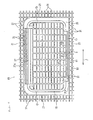
- Fig. 5 is a top view of a frame and a backing member (which is called a resin flap section for reinforcement in JP-A-2005-153545 ) included in an airbag-device cover (which is called a top-coated vehicle-interior panel in JP-A-2005-153545 ).
- Fig. 6 is an enlarged view of section VI in Fig. 5.
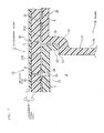
- Fig. 7 is a cross-sectional view taken along line VII-VII in Fig. 6.
- An instrument panel 1 serving as a top-coated vehicle-interior panel (airbag-device cover) according to JP-A-2005-153545 is provided with an instrument panel body 7 having a two-layer structure, which includes a resin base plate 3 composed of, for example, polypropylene (PP) and a resin top layer 5 tightly attached to a front face of the base plate 3 by, for example, vacuuming and adhered thereto with an adhesive (not shown).
- Reference numeral 59 indicates an air-release through hole which extends between the front face and a back face of the base plate 3.
- the back face of the base plate 3 of the instrument panel body 7 is provided with a groove 9 extending along an upper rim of a retainer of an airbag device and being substantially rectangular in plan view.
- a linear thin-walled portion extending along the groove 9 is a tear line 11 that serves as a guide along which the instrument panel body 7 is torn when an airbag is inflated.
- the tear line 11 is called a fracture portion in JP-A-2005-153545 .
- An inner region surrounded by the tear line 11 defines a door portion 13.
- the airbag is inflated, the instrument panel body 7 is torn along the tear line 11 so that the door portion 13 becomes separated from the instrument panel body 7.
- the door portion 13 is deployed outward towards the inside of the vehicle cabin.
- the frame 15 includes a substantially-rectangular-tube-shaped frame portion 17 that extends along an outer periphery of the tear line 11, and a flange portion 21 that extends outward laterally along the back face of the instrument panel body 7 from an upper rim of the frame portion 17.
- the flange portion 21 and the frame portion 17 are integrated with each other.
- the frame portion 17 includes a front frame wall (not shown) extending in a width direction of a vehicle, a rear frame wall 17b disposed behind and facing the front frame wall and extending in the width direction of the vehicle, a left frame wall (not shown) connecting the left edges of the front frame wall and the rear frame wall 17b and extending in a front-rear direction of the vehicle, and a right frame wall (not shown) connecting the right edges of the front frame wall and the rear frame wall 17b and extending in the front-rear direction of the vehicle.
- An upper opening of the frame portion 17 is a substantially rectangular shooting opening 19 through which the airbag inflates.
- the flange portion 21 extends entirely around the periphery of the frame portion 17.
- a resin flap 25 serving as a backing member for reinforcing the door portion 13 is disposed inside the shooting opening 19. When the airbag is inflated, the flap 25 is deployed together with the door portion 13.
- the flap 25 is composed of a highly tenacious resin material that is resistant to breakage under low temperature.
- the frame 15 (including the frame portion 17 and the flange portion 21) is for reinforcing the peripheral area of the door portion 13 and is composed of a resin material containing glass fibers having relatively high rigidity.
- a base side portion of the flap 25 is integrally provided with a hinge 27. A base 27a of the hinge 27 is joined to a connection area between the front frame wall of the frame portion 17 and the flange portion 21.
- a side portion 53 of the flap 25 opposite to the side portion with the hinge 27 is disposed on a ledge 55 provided at an inner side (i.e. a side closer to the shooting opening 19) of a connection area 57 between the rear frame wall 17b of the frame portion 17 and the flange portion 21.
- the side portion 53 of the flap 25 and the rear frame wall 17b of the frame portion 17 have a slit-like gap C 1 therebetween.
- opposite ends of the flap 25 in the width direction of the vehicle and the left and right frame walls of the frame portion 17 respectively have slit-like gaps C 2 therebetween.
- the gaps C 1 , C 2 communicate with each other.
- the tear line 11 extends so as to overlap the gaps C 1 , C 2 or extends adjacent to the gaps C 1 , C 2 .
- a top face of the flange portion 21 and a top face of the flap 25 are integrally provided with a plurality of welding ribs 31, which extend lengthwise and crosswise so as to form a lattice-like pattern.
- the welding ribs 31 are arranged at a predetermined pitch in a vibrating direction of vibration welding and are also arranged at a predetermined pitch in a direction perpendicular to the vibrating direction.
- the welding ribs 31 extending in the vibrating direction are arranged at a pitch that is narrower than the pitch of the welding ribs 31 extending in the direction perpendicular to the vibrating direction.
- the vibrating direction of vibration welding is indicated by an arrow F (left-right direction).
- the welding ribs 31 are provided with communication channels 31a through which latticed internal spaces S partitioned by the welding ribs 31 communicate with each other. Furthermore, through holes 61 extend through the flange portion 21 and the flap 25 in the vertical direction so that the latticed internal spaces S and the spaces under the flange portion 21 and the flap 25 communicate with each other.
- the flange portion 21 and the flap 25 are respectively placed over the peripheral area of the door portion 13 and the back face of the door portion 13 of the instrument panel body 7, and the welding ribs 31 are then pressed against the back face of the instrument panel body 7 (i.e. the base plate 3). Subsequently, the flange portion 21, the flap 25, and the instrument panel body 7 are relatively vibrated in the direction of the arrow F shown in Fig. 5. Thus, the contact surface between the welding ribs 31 and the base plate 3 melts as a result of friction, whereby the two become integrated with each other.
- the retainer that accommodates the airbag is placed facing the back face of the door portion 13 of the instrument panel 1 so that the airbag device is installed in the vehicle.
- the retainer is placed inside the frame portion 17 of the frame 15, and is joined to the frame portion 17 with, for example, a hook (not shown).
- the airbag is inflated, the door portion 13 becomes torn along the tear line 11 due to the expansion pressure of the airbag. As a result, the door portion 13 becomes deployed outward towards the inside of the vehicle cabin together with the flap 25.
- the tear line 11 and a welding rib 31A that is disposed on the flange portion 21 and closest to the tear line 11 are given a space therebetween having a predetermined dimension or more, and moreover, the tear line 11 and a welding rib 31B that is disposed on the flap 25 and closest to the tear line 11 are given a space therebetween having a predetermined dimension or more.
- These spaces are provided for preventing the melting material of the welding ribs 31 from entering the tear line 11 (groove 9).
- an object of the present invention to provide an airbag-device cover which has a door portion that is torn from an interior panel along a tear line in response to inflation of an airbag so as to be deployed outward towards the inside of a vehicle cabin, and which also has a reinforcement frame and a backing member respectively attached to a peripheral area and a back face of the door portion by vibration welding, such that the frame and the backing member extend to areas of the interior panel that are adjacent to the tear line. Furthermore, it is another object of the present invention to provide an airbag device equipped with such an airbag-device cover.
- An airbag-device cover (Claim 1) includes an interior panel defining a part of an interior surface of a vehicle-cabin; a door portion which is provided in the interior panel and is torn from the interior panel in response to inflation of an airbag so as to be opened outward towards the inside of the vehicle cabin; a tear line which surrounds the door portion so as to serve as a guide along which the door portion is torn; and a frame which is attached to an area of the interior panel that surrounds the door portion.
- One of attachment surfaces between the interior panel and the frame is provided with welding ribs such that the interior panel and the frame are attached to each other with the welding ribs by vibration welding.
- the welding ribs include a trunk rib extending along the tear line and a branch rib extending from the trunk rib towards the tear line.
- An airbag-device cover includes an interior panel defining a part of an interior surface of a vehicle cabin; a door portion which is provided in the interior panel and is torn from the interior panel in response to inflation of an airbag so as to be opened outward towards the inside of the vehicle cabin; a tear line which surrounds the door portion so as to serve as a guide along which the door portion is torn; a frame which is attached to an area of the interior panel that surrounds the door portion; and a backing member attached to a back face of the door portion of the interior panel.
- One of attachment surfaces between the interior panel and the frame and one of attachment surfaces between the interior panel and the backing member are provided with welding ribs.
- the interior panel and the frame are attached to each other with the corresponding welding ribs by vibration welding, and the interior panel and the backing member are attached to each other with the corresponding welding ribs by vibration welding.
- the welding ribs include a trunk rib extending along the tear line, and a branch rib extending from the trunk rib towards the tear line.
- the branch rib is preferably narrower in width than the trunk rib.
- the trunk rib preferably extends along the tear line in a vibrating direction of vibration welding, and the branch rib preferably extends crosswise to the vibrating direction.
- An airbag device (Claim 5) includes the airbag-device cover according to any one of Claims 1 to 4; a retainer disposed facing a back face of the interior panel; an airbag housed in the retainer; and an inflator for inflating the airbag.
- the branch rib of the welding ribs that joins the interior panel to the frame and the backing member, extends toward the tear line from the trunk rib extending along the tear line.
- the frame and the backing member are securely welded to areas of the interior panel that are adjacent to the tear line with the branch rib. Accordingly, when the door portion is being deployed in response to a pressure from the airbag, areas other than the tear line 11 are prevented or inhibited from being torn.
- the branch rib since the branch rib may be narrower in width than the trunk rib, the amount of melting material of the branch rib during a vibration welding process is small. Thus, the melting material of the branch rib is substantially or entirely prevented from entering the tear line.
- the trunk rib may extend along the tear line in the vibrating direction of vibration welding, and the branch rib may extend from the trunk ribs in the direction crosswise to the vibrating direction. This further prevents or inhibits the melting material of the branch rib from entering the tear line.
- Figs. 1 to 4 The embodiment of Figs. 1 to 4 is directed to an example in which the present invention is applied to the airbag-device cover shown in Figs. 5 to 7.
- the welding ribs 31 forms a lattice-like pattern on the top face of the flange portion 21 and the top face of the flap 25.
- a welding rib 31A (on the flange portion 21) and a welding rib 31B (on the flap 25), which serve as trunk ribs are disposed closest to the tear line 11 and extend in the vibrating direction of vibration welding.
- the welding rib 31A and the welding rib 31B respectively have a plurality of branch ribs 32a and a plurality of branch ribs 32b protruding therefrom towards the tear line 11.
- the branch ribs 32a, 32b extend in a direction substantially perpendicular to the vibrating direction.
- the branch ribs 32a, 32b are narrower in width than the welding ribs 31A, 31B, and moreover, the distance between adjacent branch ribs 32a, 32a and between adjacent branch ribs 32b, 32b is smaller than the distance between adjacent welding ribs 31, 31 that extend perpendicular to the vibrating direction.
- the height of the branch ribs 32a, 32b protruding respectively from the top face of the flange portion 21 and the top face of the flap 25 is equal to the height of the welding ribs 31A, 31B.
- the tips of the branch ribs 32a, 32b are extremely close to the edges of the tear line 11 (groove 9).
- a welding rib 31A' disposed closest to the tear line 11 at a side of the flange portion 21 closer to the hinge 27 also has a plurality of branch ribs 32a protruding therefrom towards the tear line 11.
- the branch ribs 32a are arranged at a predetermined pitch.
- each of the branch ribs 32a, 32b is within a range of 1.0 to 5.0 mm, and is preferably within a range of about 1.0 to 2.5 mm. Moreover, the number of the branch ribs 32a, 32b is within a range of 5 to 25 per a 100-mm-length of the corresponding welding ribs (trunk ribs) 31A, 31B, and is preferably within a range of about 10 to 18.
- the length of each of the branch ribs 32a, 32b in the direction perpendicular to the vibrating direction is within a range of 1.0 to 5.0 mm from the corresponding edge of the tear line 11 (groove 9), and preferably within a range of about 1.5 to 3.0 mm.
- the flange portion 21 and the flap 25 are respectively placed over the peripheral area of the door portion (tear line 11) and the back face of the door portion 13 of the instrument panel body 7, and the welding ribs 31 (including 31A, 31A', and 31B) and the branch ribs 32a, 32b are then pressed against the back face of the instrument panel body 7 (i.e. the base plate 3). Subsequently, the frame 15, the flap 25, and the instrument panel body 7 are relatively vibrated in the direction of an arrow F shown in Fig. 1.
- the contact surface between the welding ribs 31 and the base plate 3 and between the branch ribs 32a, 32b and the base plate 3 melts as a result of friction, whereby the welding ribs 31 and the base plate 3 become integrated with each other and the branch ribs 32a, 32b and the base plate 3 become integrated with each other.
- a retainer that accommodates an airbag is placed facing the back face of the door portion 13 of an instrument panel 1A so that an airbag device is installed in a vehicle.
- the retainer is placed inside the frame portion 17 of the frame 15, and is joined to the frame portion 17 with, for example, a hook (not shown).
- the airbag is inflated, the door portion 13 becomes torn along the tear line 11 due to the expansion pressure of the airbag. As a result, the door portion 13 becomes open outward towards the inside of the vehicle cabin together with the flap 25.
- the branch ribs 32a, 32b extending towards the tear line 11 from the welding ribs (trunk ribs) 31A, 31B surrounding the tear line 11 are welded to areas of the instrument panel body 7 that are adjacent to the tear line 11.
- the flange portion 21 of the frame 15 and the flap 25 are securely attached to these areas of the instrument panel body 7 that are adjacent to the tear line 11. Accordingly, when the door portion 13 is being deployed in response to a pressure from the airbag, areas other than the tear line 11 are prevented or inhibited from being torn.
- the melting material of the branch ribs 32a, 32b is substantially or entirely prevented from entering the tear line 11 during the vibration welding process.
- the welding ribs are provided on the top face of the flange portion 21 and the top face of the flap 25 in the above embodiment, the welding ribs may alternatively be provided on the back face of the instrument panel body 7.
- the present invention is also applicable to a type of an airbag-device cover in which a tear line extends laterally across the door portion 13, such that the door portion is deployable by being separated into a plurality of segments along the tear line. Furthermore, the present invention is also applicable to a type of an airbag-device cover in which the door portion (or a part of the door portion) is deployable by being lifted upward.
Landscapes
- Engineering & Computer Science (AREA)
- Mechanical Engineering (AREA)
- Air Bags (AREA)
Abstract
Description
- The present invention relates to an airbag-device cover which has a door portion that is torn from an interior panel along a tear line in response to inflation of an airbag so as to be deployed outward towards the inside of a vehicle cabin. In particular, the present invention relates to an airbag-device cover which has a reinforcement frame and a backing member respectively welded to a peripheral area and a back face of a door portion by vibration welding. The present invention also relates to an airbag device equipped with such an airbag-device cover.
-
JP-A-2005-153545 - Fig. 5 is a top view of a frame and a backing member (which is called a resin flap section for reinforcement in
JP-A-2005-153545 JP-A-2005-153545 - An instrument panel 1 serving as a top-coated vehicle-interior panel (airbag-device cover) according to
JP-A-2005-153545 instrument panel body 7 having a two-layer structure, which includes a resin base plate 3 composed of, for example, polypropylene (PP) and a resin top layer 5 tightly attached to a front face of the base plate 3 by, for example, vacuuming and adhered thereto with an adhesive (not shown).Reference numeral 59 indicates an air-release through hole which extends between the front face and a back face of the base plate 3. - The back face of the base plate 3 of the
instrument panel body 7 is provided with a groove 9 extending along an upper rim of a retainer of an airbag device and being substantially rectangular in plan view. A linear thin-walled portion extending along the groove 9 is atear line 11 that serves as a guide along which theinstrument panel body 7 is torn when an airbag is inflated. (Thetear line 11 is called a fracture portion inJP-A-2005-153545 tear line 11 defines adoor portion 13. When the airbag is inflated, theinstrument panel body 7 is torn along thetear line 11 so that thedoor portion 13 becomes separated from theinstrument panel body 7. Thus, thedoor portion 13 is deployed outward towards the inside of the vehicle cabin. - An area of the back face of the
instrument panel body 7 that surrounds thedoor portion 13 has aresin frame 15 attached thereto by vibration welding. Theframe 15 includes a substantially-rectangular-tube-shaped frame portion 17 that extends along an outer periphery of thetear line 11, and aflange portion 21 that extends outward laterally along the back face of theinstrument panel body 7 from an upper rim of theframe portion 17. Theflange portion 21 and theframe portion 17 are integrated with each other. - The
frame portion 17 includes a front frame wall (not shown) extending in a width direction of a vehicle, arear frame wall 17b disposed behind and facing the front frame wall and extending in the width direction of the vehicle, a left frame wall (not shown) connecting the left edges of the front frame wall and therear frame wall 17b and extending in a front-rear direction of the vehicle, and a right frame wall (not shown) connecting the right edges of the front frame wall and therear frame wall 17b and extending in the front-rear direction of the vehicle. An upper opening of theframe portion 17 is a substantially rectangular shooting opening 19 through which the airbag inflates. Theflange portion 21 extends entirely around the periphery of theframe portion 17. - A
resin flap 25 serving as a backing member for reinforcing thedoor portion 13 is disposed inside the shooting opening 19. When the airbag is inflated, theflap 25 is deployed together with thedoor portion 13. Theflap 25 is composed of a highly tenacious resin material that is resistant to breakage under low temperature. On the other hand, the frame 15 (including theframe portion 17 and the flange portion 21) is for reinforcing the peripheral area of thedoor portion 13 and is composed of a resin material containing glass fibers having relatively high rigidity. A base side portion of theflap 25 is integrally provided with ahinge 27. Abase 27a of thehinge 27 is joined to a connection area between the front frame wall of theframe portion 17 and theflange portion 21. - A
side portion 53 of theflap 25 opposite to the side portion with thehinge 27 is disposed on aledge 55 provided at an inner side (i.e. a side closer to the shooting opening 19) of aconnection area 57 between therear frame wall 17b of theframe portion 17 and theflange portion 21. - Referring to Fig. 7, the
side portion 53 of theflap 25 and therear frame wall 17b of theframe portion 17 have a slit-like gap C1 therebetween. Moreover, opposite ends of theflap 25 in the width direction of the vehicle and the left and right frame walls of theframe portion 17 respectively have slit-like gaps C2 therebetween. The gaps C1, C2 communicate with each other. Referring to Figs. 6 and 7, thetear line 11 extends so as to overlap the gaps C1, C2 or extends adjacent to the gaps C1, C2. - A top face of the
flange portion 21 and a top face of theflap 25 are integrally provided with a plurality ofwelding ribs 31, which extend lengthwise and crosswise so as to form a lattice-like pattern. Thewelding ribs 31 are arranged at a predetermined pitch in a vibrating direction of vibration welding and are also arranged at a predetermined pitch in a direction perpendicular to the vibrating direction. Generally, thewelding ribs 31 extending in the vibrating direction are arranged at a pitch that is narrower than the pitch of thewelding ribs 31 extending in the direction perpendicular to the vibrating direction. As shown in Fig. 5, in this airbag-device cover, the vibrating direction of vibration welding is indicated by an arrow F (left-right direction). - Referring to Fig. 6, in
JP-A-2005-153545 welding ribs 31 are provided withcommunication channels 31a through which latticed internal spaces S partitioned by thewelding ribs 31 communicate with each other. Furthermore, throughholes 61 extend through theflange portion 21 and theflap 25 in the vertical direction so that the latticed internal spaces S and the spaces under theflange portion 21 and theflap 25 communicate with each other. - In order to attach the
flange portion 21 and theflap 25 to theinstrument panel body 7 by vibration welding, theflange portion 21 and theflap 25 are respectively placed over the peripheral area of thedoor portion 13 and the back face of thedoor portion 13 of theinstrument panel body 7, and thewelding ribs 31 are then pressed against the back face of the instrument panel body 7 (i.e. the base plate 3). Subsequently, theflange portion 21, theflap 25, and theinstrument panel body 7 are relatively vibrated in the direction of the arrow F shown in Fig. 5. Thus, the contact surface between thewelding ribs 31 and the base plate 3 melts as a result of friction, whereby the two become integrated with each other. - Although not shown in the drawings, the retainer that accommodates the airbag is placed facing the back face of the
door portion 13 of the instrument panel 1 so that the airbag device is installed in the vehicle. In this case, the retainer is placed inside theframe portion 17 of theframe 15, and is joined to theframe portion 17 with, for example, a hook (not shown). When the airbag is inflated, thedoor portion 13 becomes torn along thetear line 11 due to the expansion pressure of the airbag. As a result, thedoor portion 13 becomes deployed outward towards the inside of the vehicle cabin together with theflap 25. - Referring to Figs. 6 and 7, in the case where the
flange portion 21 of theframe 15 and theflap 25 are to be attached to theinstrument panel body 7 with thewelding ribs 31 by vibration welding, thetear line 11 and awelding rib 31A that is disposed on theflange portion 21 and closest to thetear line 11 are given a space therebetween having a predetermined dimension or more, and moreover, thetear line 11 and awelding rib 31B that is disposed on theflap 25 and closest to thetear line 11 are given a space therebetween having a predetermined dimension or more. These spaces are provided for preventing the melting material of thewelding ribs 31 from entering the tear line 11 (groove 9). - Due to these spaces, there is a possibility that the
flange portion 21 and theflap 25 are not securely attached to areas of theinstrument panel body 7 that are adjacent to thetear line 11. If theflange portion 21 and theflap 25 are not securely attached to these areas adjacent to thetear line 11, it is highly possible that areas other than thetear line 11 may be torn when thedoor portion 13 is deployed, causing the torn pieces to scatter. - Accordingly, it is an object of the present invention to provide an airbag-device cover which has a door portion that is torn from an interior panel along a tear line in response to inflation of an airbag so as to be deployed outward towards the inside of a vehicle cabin, and which also has a reinforcement frame and a backing member respectively attached to a peripheral area and a back face of the door portion by vibration welding, such that the frame and the backing member extend to areas of the interior panel that are adjacent to the tear line. Furthermore, it is another object of the present invention to provide an airbag device equipped with such an airbag-device cover.
- An airbag-device cover according to the present invention (Claim 1) includes an interior panel defining a part of an interior surface of a vehicle-cabin; a door portion which is provided in the interior panel and is torn from the interior panel in response to inflation of an airbag so as to be opened outward towards the inside of the vehicle cabin; a tear line which surrounds the door portion so as to serve as a guide along which the door portion is torn; and a frame which is attached to an area of the interior panel that surrounds the door portion. One of attachment surfaces between the interior panel and the frame is provided with welding ribs such that the interior panel and the frame are attached to each other with the welding ribs by vibration welding. The welding ribs include a trunk rib extending along the tear line and a branch rib extending from the trunk rib towards the tear line.
- An airbag-device cover according to Claim 2 includes an interior panel defining a part of an interior surface of a vehicle cabin; a door portion which is provided in the interior panel and is torn from the interior panel in response to inflation of an airbag so as to be opened outward towards the inside of the vehicle cabin; a tear line which surrounds the door portion so as to serve as a guide along which the door portion is torn; a frame which is attached to an area of the interior panel that surrounds the door portion; and a backing member attached to a back face of the door portion of the interior panel. One of attachment surfaces between the interior panel and the frame and one of attachment surfaces between the interior panel and the backing member are provided with welding ribs. The interior panel and the frame are attached to each other with the corresponding welding ribs by vibration welding, and the interior panel and the backing member are attached to each other with the corresponding welding ribs by vibration welding. The welding ribs include a trunk rib extending along the tear line, and a branch rib extending from the trunk rib towards the tear line.
- According to the airbag-device cover set forth in Claim 3, in one of Claims 1 and 2, the branch rib is preferably narrower in width than the trunk rib.
- According to the airbag-device cover set forth in Claim 4, in any one of Claims 1 to 3, the trunk rib preferably extends along the tear line in a vibrating direction of vibration welding, and the branch rib preferably extends crosswise to the vibrating direction.
- An airbag device according to the present invention (Claim 5) includes the airbag-device cover according to any one of Claims 1 to 4; a retainer disposed facing a back face of the interior panel; an airbag housed in the retainer; and an inflator for inflating the airbag.
- In the airbag-device cover and the airbag device according to the present invention (Claims 1 to 5), the branch rib of the welding ribs, that joins the interior panel to the frame and the backing member, extends toward the tear line from the trunk rib extending along the tear line. Thus, the frame and the backing member are securely welded to areas of the interior panel that are adjacent to the tear line with the branch rib. Accordingly, when the door portion is being deployed in response to a pressure from the airbag, areas other than the
tear line 11 are prevented or inhibited from being torn. - Furthermore, as set forth in Claim 3, since the branch rib may be narrower in width than the trunk rib, the amount of melting material of the branch rib during a vibration welding process is small. Thus, the melting material of the branch rib is substantially or entirely prevented from entering the tear line.
- Furthermore, as set forth in Claim 4, the trunk rib may extend along the tear line in the vibrating direction of vibration welding, and the branch rib may extend from the trunk ribs in the direction crosswise to the vibrating direction. This further prevents or inhibits the melting material of the branch rib from entering the tear line.
- Embodiments of the present invention will now be described with reference to the drawings.
-
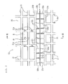
- Fig. 1 is a top view of a frame and a backing member according to an embodiment of the present invention;
- Fig. 2 is an enlarged view of section II in Fig. 1;
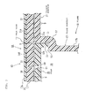
- Fig. 3 is a cross-sectional view taken along line III-III in Fig. 2;
- Fig. 4 is an enlarged perspective view of welding ribs;
- Fig. 5 is a top view of a frame and a backing member included in an airbag-device cover according to a conventional example;
- Fig. 6 is an enlarged view of section VI in Fig. 5; and
- Fig. 7 is a cross-sectional view taken along line VII-VII in Fig. 6.
- The embodiment of Figs. 1 to 4 is directed to an example in which the present invention is applied to the airbag-device cover shown in Figs. 5 to 7.
- In this embodiment, the
welding ribs 31 forms a lattice-like pattern on the top face of theflange portion 21 and the top face of theflap 25. Awelding rib 31A (on the flange portion 21) and awelding rib 31B (on the flap 25), which serve as trunk ribs are disposed closest to thetear line 11 and extend in the vibrating direction of vibration welding. Thewelding rib 31A and thewelding rib 31B respectively have a plurality ofbranch ribs 32a and a plurality ofbranch ribs 32b protruding therefrom towards thetear line 11. Thebranch ribs - Referring to Figs. 2 and 4, the
branch ribs welding ribs adjacent branch ribs adjacent branch ribs adjacent welding ribs branch ribs flange portion 21 and the top face of theflap 25 is equal to the height of thewelding ribs branch ribs - Referring to Fig. 1, in this embodiment, a
welding rib 31A' disposed closest to thetear line 11 at a side of theflange portion 21 closer to thehinge 27 also has a plurality ofbranch ribs 32a protruding therefrom towards thetear line 11. Thebranch ribs 32a are arranged at a predetermined pitch. - The width of each of the
branch ribs branch ribs branch ribs - Other configurations of the airbag-device cover in this embodiment are the same as those of the airbag-device cover shown in Figs. 5 to 7. Therefore, components shown in Figs. 1 to 4 that are equivalent to those shown in Figs. 5 to 7 are given the same reference numerals, and descriptions of those components will not be repeated.
- In this embodiment, the
flange portion 21 and theflap 25 are respectively placed over the peripheral area of the door portion (tear line 11) and the back face of thedoor portion 13 of theinstrument panel body 7, and the welding ribs 31 (including 31A, 31A', and 31B) and thebranch ribs frame 15, theflap 25, and theinstrument panel body 7 are relatively vibrated in the direction of an arrow F shown in Fig. 1. Thus, the contact surface between thewelding ribs 31 and the base plate 3 and between thebranch ribs welding ribs 31 and the base plate 3 become integrated with each other and thebranch ribs - Although not shown in the drawings, a retainer that accommodates an airbag is placed facing the back face of the
door portion 13 of aninstrument panel 1A so that an airbag device is installed in a vehicle. In this case, the retainer is placed inside theframe portion 17 of theframe 15, and is joined to theframe portion 17 with, for example, a hook (not shown). When the airbag is inflated, thedoor portion 13 becomes torn along thetear line 11 due to the expansion pressure of the airbag. As a result, thedoor portion 13 becomes open outward towards the inside of the vehicle cabin together with theflap 25. - In the
instrument panel 1A, thebranch ribs tear line 11 from the welding ribs (trunk ribs) 31A, 31B surrounding thetear line 11 are welded to areas of theinstrument panel body 7 that are adjacent to thetear line 11. Thus, theflange portion 21 of theframe 15 and theflap 25 are securely attached to these areas of theinstrument panel body 7 that are adjacent to thetear line 11. Accordingly, when thedoor portion 13 is being deployed in response to a pressure from the airbag, areas other than thetear line 11 are prevented or inhibited from being torn. - Furthermore, according to this embodiment, since the
branch ribs welding ribs branch ribs tear line 11 during the vibration welding process. - The above-described embodiment is only an example of the present invention, and therefore, the present invention is not limited to the above embodiment.
- For example, although the welding ribs are provided on the top face of the
flange portion 21 and the top face of theflap 25 in the above embodiment, the welding ribs may alternatively be provided on the back face of theinstrument panel body 7. - Furthermore, although the above embodiment is directed to an example in which the present invention is applied to a type of an airbag-device cover that has the
tear line 11 provided only around the periphery of thedoor portion 13, the present invention is also applicable to a type of an airbag-device cover in which a tear line extends laterally across thedoor portion 13, such that the door portion is deployable by being separated into a plurality of segments along the tear line. Furthermore, the present invention is also applicable to a type of an airbag-device cover in which the door portion (or a part of the door portion) is deployable by being lifted upward.
Claims (5)
- An airbag-device cover comprising:an interior panel defining a part of an interior surface of a vehicle cabin;a door portion which is provided in the interior panel and is torn from the interior panel in response to inflation of an airbag so as to be opened outward towards the inside of the vehicle cabin;a tear line which surrounds the door portion so as to serve as a guide along which the door portion is torn; anda frame which is attached to an area of the interior panel that surrounds the door portion,wherein one of attachment surfaces between the interior panel and the frame is provided with welding ribs such that the interior panel and the frame are attached to each other with the welding ribs by vibration welding, andwherein the welding ribs include a trunk rib extending along the tear line and a branch rib extending from the trunk rib towards the tear line.
- An airbag-device cover comprising:an interior panel defining a part of an interior surface of a vehicle cabin;a door portion which is provided in the interior panel and is torn from the interior panel in response to inflation of an airbag so as to be opened outward towards the inside of the vehicle cabin;a tear line which surrounds the door portion so as to serve as a guide along which the door portion is torn;a frame which is attached to an area of the interior panel that surrounds the door portion; anda backing member attached to a back face of the door portion of the interior panel,wherein one of attachment surfaces between the interior panel and the frame and one of attachment surfaces between the interior panel and the backing member are provided with welding ribs, the interior panel and the frame being attached to each other with the corresponding welding ribs by vibration welding, the interior panel and the backing member being attached to each other with the corresponding welding ribs by vibration welding, andwherein the welding ribs include a trunk rib extending along the tear line, and a branch rib extending from the trunk rib towards the tear line.
- The airbag-device cover according to one of Claims 1 and 2, wherein the branch rib is narrower in width than the trunk rib.
- The airbag-device cover according to any one of Claims 1 to 3, wherein the trunk rib extends along the tear line in a vibrating direction of vibration welding, and wherein the branch rib extends crosswise to the vibrating direction.
- An airbag device comprising:the airbag-device cover according to any one of Claims 1 to 4;a retainer disposed facing a back face of the airbag-device cover;an airbag housed in the retainer; andan inflator for inflating the airbag.
Applications Claiming Priority (1)
| Application Number | Priority Date | Filing Date | Title |
|---|---|---|---|
| JP2005225626A JP2007038868A (en) | 2005-08-03 | 2005-08-03 | Cover for air bag device and air bag device |
Publications (2)
| Publication Number | Publication Date |
|---|---|
| EP1749707A2 true EP1749707A2 (en) | 2007-02-07 |
| EP1749707A3 EP1749707A3 (en) | 2008-04-02 |
Family
ID=37307294
Family Applications (1)
| Application Number | Title | Priority Date | Filing Date |
|---|---|---|---|
| EP06013827A Withdrawn EP1749707A3 (en) | 2005-08-03 | 2006-07-04 | Airbag-device cover and airbag device |
Country Status (4)
| Country | Link |
|---|---|
| US (1) | US20070029763A1 (en) |
| EP (1) | EP1749707A3 (en) |
| JP (1) | JP2007038868A (en) |
| CN (1) | CN1907764A (en) |
Cited By (2)
| Publication number | Priority date | Publication date | Assignee | Title |
|---|---|---|---|---|
| US11932193B1 (en) * | 2023-04-13 | 2024-03-19 | Faurecia Interior Systems, Inc. | Vehicle interior panel for use over a deployable airbag and method of manufacturing |
| US20240174196A1 (en) * | 2022-11-25 | 2024-05-30 | Hyundai Mobis Co., Ltd. | Passenger air bag device |
Families Citing this family (16)
| Publication number | Priority date | Publication date | Assignee | Title |
|---|---|---|---|---|
| US7695001B2 (en) * | 2005-09-01 | 2010-04-13 | Trw Vehicle Safety Systems Inc. | Vehicle protection apparatus with cover having a rupturable portion with tear tabs |
| US7798518B2 (en) * | 2006-04-27 | 2010-09-21 | Magna International, Inc. | Trim panel with pre-weakened segment and bridge |
| JP5042552B2 (en) * | 2006-08-01 | 2012-10-03 | タカタ株式会社 | Airbag cover, instrument panel, airbag device |
| JP4976315B2 (en) * | 2008-01-18 | 2012-07-18 | タカタ株式会社 | Airbag cover, instrument panel, airbag device, airbag housing |
| JP4954916B2 (en) * | 2008-02-06 | 2012-06-20 | タカタ株式会社 | Airbag cover, instrument panel, airbag device, airbag housing |
| JP2010168027A (en) * | 2008-09-29 | 2010-08-05 | Toyoda Gosei Co Ltd | Airbag door |
| JP2010083166A (en) * | 2008-09-29 | 2010-04-15 | Toyoda Gosei Co Ltd | Airbag door |
| JP5280219B2 (en) * | 2009-01-21 | 2013-09-04 | 株式会社イノアックコーポレーション | Spoiler |
| JP5611619B2 (en) * | 2010-03-04 | 2014-10-22 | タカタ株式会社 | Vehicle interior panel and airbag device |
| US8251435B2 (en) * | 2010-07-19 | 2012-08-28 | Inoac Corporation | Spoiler |
| JP2012245859A (en) * | 2011-05-26 | 2012-12-13 | Takata Corp | Air bag device for passenger seat |
| CN105398341B (en) * | 2015-11-23 | 2018-01-19 | 天津华夏联盛汽车部件有限公司 | A kind of panel assembly with the passenger side air bag door part |
| DE102018200137A1 (en) * | 2018-01-08 | 2019-07-11 | Volkswagen Aktiengesellschaft | Interior cover for receiving an airbag to protect an occupant in a driver's cab of a motor vehicle |
| ES2892152T3 (en) * | 2018-01-22 | 2022-02-02 | Motherson Innovations Co Ltd | Airbag guide device for guiding an airbag of a motor vehicle, airbag construction unit with this airbag guide device, as well as inner lining component and method for manufacturing a corresponding inner lining component comprising such an airbag guide device |
| JP7020188B2 (en) * | 2018-03-02 | 2022-02-16 | トヨタ自動車株式会社 | Instrument panel structure |
| JP7222375B2 (en) * | 2020-03-25 | 2023-02-15 | 豊田合成株式会社 | Resin molded product |
Citations (1)
| Publication number | Priority date | Publication date | Assignee | Title |
|---|---|---|---|---|
| JP2005153545A (en) | 2003-11-20 | 2005-06-16 | Nishikawa Kasei Co Ltd | Interior panel for vehicle with skin |
Family Cites Families (7)
| Publication number | Priority date | Publication date | Assignee | Title |
|---|---|---|---|---|
| US6761375B2 (en) * | 2000-04-26 | 2004-07-13 | Sanko Gosei Kabushiki Kaisha | Structure of reinforcement plate member used in automobile airbag apparatus |
| ES2215808T3 (en) * | 2000-04-28 | 2004-10-16 | Inoac Corporation | BREAKABLE STRUCTURE OF AN AIRBAG PANEL. |
| US6692017B2 (en) * | 2000-12-25 | 2004-02-17 | Daihatsu Motor Co., Ltd. | Airbag apparatus for automobile |
| US7093849B2 (en) * | 2002-09-24 | 2006-08-22 | Nihon Plast Co., Ltd. | Cover body for air bag apparatus |
| DE60319164T2 (en) * | 2002-10-15 | 2008-05-21 | Daikyonishikawa Corp. | Airbag cover for a vehicle |
| EP1431134B1 (en) * | 2002-12-10 | 2006-04-26 | Calsonic Kansei Corporation | Door of Airbag apparatus for vehicle |
| US20050269804A1 (en) * | 2004-05-27 | 2005-12-08 | Satoshi Yamada | Cover of air bag apparatus and manufacturing method thereof |
-
2005
- 2005-08-03 JP JP2005225626A patent/JP2007038868A/en not_active Withdrawn
-
2006
- 2006-07-04 EP EP06013827A patent/EP1749707A3/en not_active Withdrawn
- 2006-07-20 US US11/489,615 patent/US20070029763A1/en not_active Abandoned
- 2006-08-03 CN CNA2006101086861A patent/CN1907764A/en active Pending
Patent Citations (1)
| Publication number | Priority date | Publication date | Assignee | Title |
|---|---|---|---|---|
| JP2005153545A (en) | 2003-11-20 | 2005-06-16 | Nishikawa Kasei Co Ltd | Interior panel for vehicle with skin |
Cited By (3)
| Publication number | Priority date | Publication date | Assignee | Title |
|---|---|---|---|---|
| US20240174196A1 (en) * | 2022-11-25 | 2024-05-30 | Hyundai Mobis Co., Ltd. | Passenger air bag device |
| US12030452B2 (en) * | 2022-11-25 | 2024-07-09 | Hyundai Mobis Co., Ltd. | Passenger air bag device |
| US11932193B1 (en) * | 2023-04-13 | 2024-03-19 | Faurecia Interior Systems, Inc. | Vehicle interior panel for use over a deployable airbag and method of manufacturing |
Also Published As
| Publication number | Publication date |
|---|---|
| EP1749707A3 (en) | 2008-04-02 |
| JP2007038868A (en) | 2007-02-15 |
| US20070029763A1 (en) | 2007-02-08 |
| CN1907764A (en) | 2007-02-07 |
Similar Documents
| Publication | Publication Date | Title |
|---|---|---|
| US20070029763A1 (en) | Airbag-device cover and airbag device | |
| US5069477A (en) | Pad for air bag device | |
| EP1884418B1 (en) | Airbag cover, instrumental panel, and airbag apparatus | |
| US20130001932A1 (en) | Vehicle interior panel, and airbag device | |
| ITRM950645A1 (en) | INSTRUMENT PANEL WITH COVER FOR THE INTEGRATED TILTING AIR CUSHION FOR VEHICLES | |
| US6257658B1 (en) | Open roof construction for a vehicle | |
| JPH0427636A (en) | Air bag storage cover | |
| US20070052211A1 (en) | Airbag device and covering member thereof | |
| EP0486708B1 (en) | Module cover of air bag | |
| US7275759B2 (en) | Cover for use in airbag apparatus, and airbag apparatus | |
| US6789816B2 (en) | Passenger airbag assembly | |
| EP1393990A2 (en) | Air-bag-door-equipped vehicle interior trim article and method for fabricating the same | |
| US8641084B2 (en) | Ageing-resistant mounting for inflatable airbag module | |
| KR100306497B1 (en) | Improved Airbag Cover | |
| CN115610367A (en) | air bag cover | |
| US20060202445A1 (en) | Instrument panel provided with a trap held by clamps | |
| EP1700756A2 (en) | Cover for use in airbag apparatus, and airbag apparatus | |
| JP2023031194A (en) | Air bag cover | |
| JP4610998B2 (en) | Instrument panel with integrated airbag door | |
| JP2008149810A (en) | Airbag door structure | |
| JP4371780B2 (en) | Interior panel for vehicle with skin | |
| EP4375148B1 (en) | Passenger air bag device | |
| CN115716460A (en) | air bag cover | |
| JP5199817B2 (en) | Airbag door | |
| JP7337673B2 (en) | air bag door |
Legal Events
| Date | Code | Title | Description |
|---|---|---|---|
| PUAI | Public reference made under article 153(3) epc to a published international application that has entered the european phase |
Free format text: ORIGINAL CODE: 0009012 |
|
| AK | Designated contracting states |
Kind code of ref document: A2 Designated state(s): AT BE BG CH CY CZ DE DK EE ES FI FR GB GR HU IE IS IT LI LT LU LV MC NL PL PT RO SE SI SK TR |
|
| AX | Request for extension of the european patent |
Extension state: AL BA HR MK YU |
|
| PUAL | Search report despatched |
Free format text: ORIGINAL CODE: 0009013 |
|
| AK | Designated contracting states |
Kind code of ref document: A3 Designated state(s): AT BE BG CH CY CZ DE DK EE ES FI FR GB GR HU IE IS IT LI LT LU LV MC NL PL PT RO SE SI SK TR |
|
| AX | Request for extension of the european patent |
Extension state: AL BA HR MK YU |
|
| AKX | Designation fees paid |
Designated state(s): DE FR GB SE |
|
| STAA | Information on the status of an ep patent application or granted ep patent |
Free format text: STATUS: THE APPLICATION IS DEEMED TO BE WITHDRAWN |
|
| 18D | Application deemed to be withdrawn |
Effective date: 20081003 |