EP1759935A1 - Airbag device and covering member thereof - Google Patents
Airbag device and covering member thereof Download PDFInfo
- Publication number
- EP1759935A1 EP1759935A1 EP06016668A EP06016668A EP1759935A1 EP 1759935 A1 EP1759935 A1 EP 1759935A1 EP 06016668 A EP06016668 A EP 06016668A EP 06016668 A EP06016668 A EP 06016668A EP 1759935 A1 EP1759935 A1 EP 1759935A1
- Authority
- EP
- European Patent Office
- Prior art keywords
- backplate
- airbag
- covering member
- section
- cover body
- Prior art date
- Legal status (The legal status is an assumption and is not a legal conclusion. Google has not performed a legal analysis and makes no representation as to the accuracy of the status listed.)
- Withdrawn
Links
Images

Classifications
-
- B—PERFORMING OPERATIONS; TRANSPORTING
- B60—VEHICLES IN GENERAL
- B60R—VEHICLES, VEHICLE FITTINGS, OR VEHICLE PARTS, NOT OTHERWISE PROVIDED FOR
- B60R21/00—Arrangements or fittings on vehicles for protecting or preventing injuries to occupants or pedestrians in case of accidents or other traffic risks
- B60R21/02—Occupant safety arrangements or fittings, e.g. crash pads
- B60R21/16—Inflatable occupant restraints or confinements designed to inflate upon impact or impending impact, e.g. air bags
- B60R21/20—Arrangements for storing inflatable members in their non-use or deflated condition; Arrangement or mounting of air bag modules or components
- B60R21/215—Arrangements for storing inflatable members in their non-use or deflated condition; Arrangement or mounting of air bag modules or components characterised by the covers for the inflatable member
- B60R21/2165—Arrangements for storing inflatable members in their non-use or deflated condition; Arrangement or mounting of air bag modules or components characterised by the covers for the inflatable member characterised by a tear line for defining a deployment opening
-
- B—PERFORMING OPERATIONS; TRANSPORTING
- B60—VEHICLES IN GENERAL
- B60R—VEHICLES, VEHICLE FITTINGS, OR VEHICLE PARTS, NOT OTHERWISE PROVIDED FOR
- B60R21/00—Arrangements or fittings on vehicles for protecting or preventing injuries to occupants or pedestrians in case of accidents or other traffic risks
- B60R21/02—Occupant safety arrangements or fittings, e.g. crash pads
- B60R21/16—Inflatable occupant restraints or confinements designed to inflate upon impact or impending impact, e.g. air bags
- B60R21/20—Arrangements for storing inflatable members in their non-use or deflated condition; Arrangement or mounting of air bag modules or components
- B60R21/215—Arrangements for storing inflatable members in their non-use or deflated condition; Arrangement or mounting of air bag modules or components characterised by the covers for the inflatable member
- B60R2021/21537—Arrangements for storing inflatable members in their non-use or deflated condition; Arrangement or mounting of air bag modules or components characterised by the covers for the inflatable member characterised by hinges
Definitions
- the present invention relates to airbag devices and covering members thereof that are disposed in fast moving bodies such as automobiles, and in particular, it relates to airbag devices and covering members thereof that are suitable for passenger airbag devices. Specifically, the present invention relates to covering members including door sections and airbag devices including the covering members.
- a passenger airbag device is disposed in front of a front passenger seat, and includes a container having an opening in the front thereof, an airbag accommodated in the container, a gas generator for inflating the airbag, and a covering member that covers the front of the container.
- the gas generator blows gas and the airbag is inflated, the covering member is opened by the airbag that pushes the covering member.
- the airbag is deployed in the vehicle cabin.
- a covering member including an instrument panel serving as a plastic cover body and a plastic airbag bracket serving both as a backplate and a connecting member fixed to the back face of the instrument panel by vibration welding is disclosed in JP-A-2002-12116 (Patent Document 1).
- This airbag bracket is connected to an airbag case serving as a container.
- the airbag bracket includes a mounting section connected to the airbag case and a back-face section fixed to the back face of a door section of the instrument panel.
- the mounting section and the back-face section are integrated via a U-shaped hinge section, and composed of the same synthetic resin.
- the hinge section allows the door section to start opening smoothly.
- An object of the present invention is to provide a covering member that allows a back face in a backplate, the back face fixed to a door section of a cover body, to start opening very easily during opening of the door section, and to provide an airbag device including the covering member.
- a covering member for an airbag device includes a cover body having a door section that is opened when an airbag is inflated, and a backplate integrated with the back face of the cover body.
- the covering member is characterized in that at least a hinge section in the backplate, the hinge section being bent when the door section is opened, is formed of a flexible component.
- the covering member according to Claim 2 which is dependent on Claim 1, is characterized in that the backplate includes a first backplate integrated with the door section of the cover body and a second backplate separated from the first backplate and integrated with a peripheral section of the cover body enclosing the door section, and the first backplate and the second backplate are connected by the flexible component.
- a covering member for an airbag device includes a cover body having a door section that is opened when an airbag is inflated, and a backplate integrated with the back face of the cover body.
- the covering member is characterized in that the backplate is integrated with a peripheral section of the cover body; enclosing the door sectionand a flexible component extends along the back face of the door section, and is fixed to the backplate and the back face of the door section.
- the covering member according to Claim 4 which is dependent on any one of Claims 1 to 3, is characterized in that the flexible component is a mesh, a sheet, or a metallic component.
- the covering member according to Claim 5, which is dependent on any one of Claims 1 to 4, is characterized in that the cover body is a lid or an instrument panel.
- An airbag device (Claim 6) includes a container having an opening in the front thereof, an airbag accommodated in the container, a gas generator for inflating the airbag, and a covering member that covers the front of the container.
- the airbag device is characterized in that the covering member is the covering member according to the present invention.
- the hinge section of the backplate is composed of a flexible material, and thus the door section starts opening smoothly when the cover body is opened.
- the first backplate fixed to the door section of the cover body and the second backplate fixed to the peripheral section of the cover body are separate components, and the backplates are connected to each other by the flexible component. Therefore, when the cover body is opened, the door section starts opening very smoothly without any or almost any flexing resistance from the first and second backplates.
- the backplate is not fixed to the door section of the cover body, and only the flexible component is fixed to the door section of the covering body. Therefore, when the cover body is opened, the door section starts opening smoothly without flexing resistance from the backplate.
- the door section can start opening considerably more smoothly.
- the cover body may be either a lid or an instrument panel.
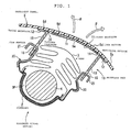
- a passenger airbag device 1 includes a container 2 that is approximately rectangular when viewed in plan, a folded airbag 3 disposed inside the container 2, and an approximately columnar inflator 4 for inflating the airbag 3.
- the airbag 3 is connected to the bottom portion of the container 2 via an airbag retaining plate 3P extending along the bottom surface of the container 2.
- An instrument panel 5 covers an opening adjacent to the top of the container 2, and a tear line 5a from which cleavage starts is formed on the back face of the instrument panel 5. Both sides of the tear line 5a are defined as door sections 5d that are opened when the airbag 3 is inflated. A peripheral section 5s encloses the door sections 5d.
- a backplate unit 10 is fixed to the back face of the instrument panel 5 by vibration welding or the like.
- the backplate unit 10 includes first backplates 11 fixed on the back face of the door sections 5d, a second backplate 12 fixed on the peripheral section 5s enclosing the door sections 5d, and a footboard 13 extending from the second backplate 12 so as to stand straight.
- the first backplates 11, the second backplate 12, and the footboard 13 are separate components, and gaps are provided between the first backplates 11 and the second backplate 12.
- the first backplates 11, the second backplate 12, and the footboard 13 are composed of synthetic resin.
- the backplate unit 10 includes flexible components 14 that connect the first backplates 11 and the second backplate 12.
- the flexible components 14 are formed of meshes composed of plastic fibers or metal wires, plastic sheets, metal sheets, or the like. First ends of the flexible components 14 are fixed to the first backplates 11 by embedding or the like, and second ends of the flexible components 14 are fixed to the second backplate 12 by embedding or the like.
- base ends of the first backplates 11 are adjacent to the second backplate 12, and leading ends of the first backplates 11 extend to the vicinity of the edge of the tear line 5a.
- the footboard 13 is a plate extending approximately perpendicular to the instrument panel 5.
- the footboard 13 includes openings 15 for attaching hook portions 21 of fixtures 20 (described below).
- the fixtures 20 are fixed on edge portions of the container 2 adjacent to the windshield and adjacent to the passenger by welding or the like.
- the approximately L-shaped hook portions 21 are integrally formed at ends of the fixtures 20 adjacent to the instrument panel 5.
- the footboard 13 and the container 2 are connected by fitting the hook portions 21 into the openings 15 of the footboard 13.
- the first backplates 11 integrated with the door sections 5d start opening, and the flexible components 14 are bent.
- the flexible components 14 can be bent very easily, and do not apply resistance when the door sections 5d starts opening. Therefore, the door sections 5d can start opening very smoothly. Since the first backplates 11 and the second backplate 12 are connected via the flexible components 14, the door sections 5d are not blown off even when large stress is concentrated in the vicinity of connections between the peripheral section 5s and the door sections 5d.
- Fig. 2 is a cross-sectional view of an airbag device 1A according to another embodiment.
- a backplate unit 10A does not include first backplates 11, but includes only a second backplate 12 and footboard 13.
- the second backplate 12 is fixed to the back face of a peripheral section 5s of an instrument panel 5.
- First ends of flexible components 14A are fixed to the second backplate 12 by embedding or the like.
- Second ends of the flexible components 14A extend along the back faces of door sections 5d, and are fixed on the back faces of the door sections 5d by bonding or the like.
- the first ends of the flexible components 14A are embedded in the second backplate 12 on the side of the peripheral section 5s adjacent to the passenger and adjacent to the windshield.
- the second ends of the flexible components 14A extend to the vicinity of a tear line 5a.
- the door sections 5d when an inflator 4 blows gas, the door sections 5d are opened outward in the directions of arrows ⁇ . At this time, the door sections 5d can start opening very smoothly since the flexible components 14 can easily be bent. Moreover, since the flexible components 14A are fixed to both the door sections 5d and the peripheral section 5s, the door sections 5d are not blown off.
- the backplate unit is fixed to the instrument panel 5 in the above-described embodiments, but it may be fixed to a lid of the airbag device.
Abstract
A covering member is provided which allows a back face in a backplate, the back face fixed to a door section of a cover body, to start opening very easily during opening of the door section, and to provide an airbag device including the covering member. The airbag device 1 includes a container 2 having an opening in the front thereof, a folded airbag 3 accommodated in the container 2, an inflator 4 for inflating the airbag 3, door sections 5d of an instrument panel 5 covering the front of the container 2, and a backplate unit 10. First backplates 11 of the backplate unit 10 are fixed to the door sections 5d, and a second backplate 12 is fixed to a peripheral section 5s. The first backplates 11 and the second backplate 12 are connected to each other by flexible components 14 formed of meshes (Fig. 1).
Description
- The present invention relates to airbag devices and covering members thereof that are disposed in fast moving bodies such as automobiles, and in particular, it relates to airbag devices and covering members thereof that are suitable for passenger airbag devices. Specifically, the present invention relates to covering members including door sections and airbag devices including the covering members.
- A passenger airbag device is disposed in front of a front passenger seat, and includes a container having an opening in the front thereof, an airbag accommodated in the container, a gas generator for inflating the airbag, and a covering member that covers the front of the container. When the gas generator blows gas and the airbag is inflated, the covering member is opened by the airbag that pushes the covering member. Thus, the airbag is deployed in the vehicle cabin.
- A covering member including an instrument panel serving as a plastic cover body and a plastic airbag bracket serving both as a backplate and a connecting member fixed to the back face of the instrument panel by vibration welding is disclosed in
JP-A-2002-12116 - According to
JP-A-2002-12116 - An object of the present invention is to provide a covering member that allows a back face in a backplate, the back face fixed to a door section of a cover body, to start opening very easily during opening of the door section, and to provide an airbag device including the covering member.
- A covering member for an airbag device according to a first invention (Claim 1) includes a cover body having a door section that is opened when an airbag is inflated, and a backplate integrated with the back face of the cover body. The covering member is characterized in that at least a hinge section in the backplate, the hinge section being bent when the door section is opened, is formed of a flexible component.
- The covering member according to
Claim 2, which is dependent on Claim 1, is characterized in that the backplate includes a first backplate integrated with the door section of the cover body and a second backplate separated from the first backplate and integrated with a peripheral section of the cover body enclosing the door section, and the first backplate and the second backplate are connected by the flexible component. - A covering member for an airbag device according to a second invention (Claim 3) includes a cover body having a door section that is opened when an airbag is inflated, and a backplate integrated with the back face of the cover body. The covering member is characterized in that the backplate is integrated with a peripheral section of the cover body; enclosing the door sectionand a flexible component extends along the back face of the door section, and is fixed to the backplate and the back face of the door section.
- The covering member according to Claim 4, which is dependent on any one of Claims 1 to 3, is characterized in that the flexible component is a mesh, a sheet, or a metallic component.
- The covering member according to
Claim 5, which is dependent on any one of Claims 1 to 4, is characterized in that the cover body is a lid or an instrument panel. - An airbag device according to the present invention (Claim 6) includes a container having an opening in the front thereof, an airbag accommodated in the container, a gas generator for inflating the airbag, and a covering member that covers the front of the container. The airbag device is characterized in that the covering member is the covering member according to the present invention.
- In the covering member of the airbag according to Claim 1 and an airbag device including the same, the hinge section of the backplate is composed of a flexible material, and thus the door section starts opening smoothly when the cover body is opened.
- According to
Claim 2, the first backplate fixed to the door section of the cover body and the second backplate fixed to the peripheral section of the cover body are separate components, and the backplates are connected to each other by the flexible component. Therefore, when the cover body is opened, the door section starts opening very smoothly without any or almost any flexing resistance from the first and second backplates. - According to
Claim 3, the backplate is not fixed to the door section of the cover body, and only the flexible component is fixed to the door section of the covering body. Therefore, when the cover body is opened, the door section starts opening smoothly without flexing resistance from the backplate. - When the flexible component is formed of a mesh, a sheet, or a metallic component, the door section can start opening considerably more smoothly.
- The cover body may be either a lid or an instrument panel.
- Embodiments of the present invention will now be described with reference to the drawings:
- Fig. 1 is a cross-sectional view of a passenger airbag device according to an embodiment; and
- Fig. 2 is a cross-sectional view of a passenger airbag device according to another embodiment.
- The right side in Fig. 1 is adjacent to the passenger, and the left side is adjacent to a windshield.
A passenger airbag device 1 includes acontainer 2 that is approximately rectangular when viewed in plan, a foldedairbag 3 disposed inside thecontainer 2, and an approximately columnar inflator 4 for inflating theairbag 3. Theairbag 3 is connected to the bottom portion of thecontainer 2 via anairbag retaining plate 3P extending along the bottom surface of thecontainer 2. - An
instrument panel 5 covers an opening adjacent to the top of thecontainer 2, and atear line 5a from which cleavage starts is formed on the back face of theinstrument panel 5. Both sides of thetear line 5a are defined asdoor sections 5d that are opened when theairbag 3 is inflated.
Aperipheral section 5s encloses thedoor sections 5d. - A
backplate unit 10 is fixed to the back face of theinstrument panel 5 by vibration welding or the like. Thebackplate unit 10 includesfirst backplates 11 fixed on the back face of thedoor sections 5d, asecond backplate 12 fixed on theperipheral section 5s enclosing thedoor sections 5d, and afootboard 13 extending from thesecond backplate 12 so as to stand straight. Thefirst backplates 11, thesecond backplate 12, and thefootboard 13 are separate components, and gaps are provided between thefirst backplates 11 and thesecond backplate 12. Thefirst backplates 11, thesecond backplate 12, and thefootboard 13 are composed of synthetic resin. - Furthermore, the
backplate unit 10 includesflexible components 14 that connect thefirst backplates 11 and thesecond backplate 12. Theflexible components 14 are formed of meshes composed of plastic fibers or metal wires, plastic sheets, metal sheets, or the like. First ends of theflexible components 14 are fixed to thefirst backplates 11 by embedding or the like, and second ends of theflexible components 14 are fixed to thesecond backplate 12 by embedding or the like. - As shown in the drawing, base ends of the
first backplates 11 are adjacent to thesecond backplate 12, and leading ends of thefirst backplates 11 extend to the vicinity of the edge of thetear line 5a. - The
footboard 13 is a plate extending approximately perpendicular to theinstrument panel 5. Thefootboard 13 includesopenings 15 for attachinghook portions 21 of fixtures 20 (described below). - The
fixtures 20 are fixed on edge portions of thecontainer 2 adjacent to the windshield and adjacent to the passenger by welding or the like. The approximately L-shaped hook portions 21 are integrally formed at ends of thefixtures 20 adjacent to theinstrument panel 5. Thefootboard 13 and thecontainer 2 are connected by fitting thehook portions 21 into theopenings 15 of thefootboard 13. - In this airbag device 1 having the above-described structure, when the inflator 4 blows gas and the
airbag 3 is inflated, thedoor sections 5d cleave along thetear line 5a such that thedoor sections 5d start opening outward in the directions of arrows θ. Thus, theairbag 3 expands in front of the passenger so as to restrain the passenger. - When the
door sections 5d start opening, thefirst backplates 11 integrated with thedoor sections 5d start opening, and theflexible components 14 are bent. Theflexible components 14 can be bent very easily, and do not apply resistance when thedoor sections 5d starts opening. Therefore, thedoor sections 5d can start opening very smoothly. Since thefirst backplates 11 and thesecond backplate 12 are connected via theflexible components 14, thedoor sections 5d are not blown off even when large stress is concentrated in the vicinity of connections between theperipheral section 5s and thedoor sections 5d. - Fig. 2 is a cross-sectional view of an
airbag device 1A according to another embodiment. - In this embodiment, a
backplate unit 10A does not includefirst backplates 11, but includes only asecond backplate 12 andfootboard 13. Thesecond backplate 12 is fixed to the back face of aperipheral section 5s of aninstrument panel 5. - First ends of
flexible components 14A are fixed to thesecond backplate 12 by embedding or the like. Second ends of theflexible components 14A extend along the back faces ofdoor sections 5d, and are fixed on the back faces of thedoor sections 5d by bonding or the like. - As shown in the drawing, the first ends of the
flexible components 14A are embedded in thesecond backplate 12 on the side of theperipheral section 5s adjacent to the passenger and adjacent to the windshield. The second ends of theflexible components 14A extend to the vicinity of atear line 5a. - Structures other than these components are the same as in those shown in Fig. 1, and components having the same reference numerals or symbols correspond to the same components.
- Also in this embodiment, when an inflator 4 blows gas, the
door sections 5d are opened outward in the directions of arrows θ. At this time, thedoor sections 5d can start opening very smoothly since theflexible components 14 can easily be bent. Moreover, since theflexible components 14A are fixed to both thedoor sections 5d and theperipheral section 5s, thedoor sections 5d are not blown off. - The above-described embodiments are merely examples for carrying out the present invention, and embodiments other than those shown in the drawings are permissible within the scope of the present invention. For example, only one door section may be provided by forming the
tear line 5a along theperipheral section 5s adjacent to the passenger. As a matter of course, three or more door sections that are opened in three or four directions may also be provided. - Moreover, the backplate unit is fixed to the
instrument panel 5 in the above-described embodiments, but it may be fixed to a lid of the airbag device.
Claims (6)
- A covering member for an airbag device, comprising:a cover body having a door section that is opened when an airbag is inflated; anda backplate integrated with the back face of the cover body, whereinat least a hinge section in the backplate, the hinge section being bent when the door section is opened, is formed of a flexible component.
- The covering member according to Claim 1, wherein
the backplate comprises a first backplate integrated with the door section of the cover body and a second backplate separated from the first backplate and integrated with a peripheral section of the cover body enclosing the door section; and
the first backplate and the second backplate are connected by the flexible component. - A covering member for an airbag device, comprising:a cover body having a door section that is opened when an airbag is inflated; anda backplate integrated with the back face of the cover body, whereinthe backplate is integrated with a peripheral section of the cover body enclosing the door section; anda flexible component extends along the back face of the door section, and is fixed to the backplate and the back face of the door section.
- The covering member according to any one of Claims 1 to 3, wherein the flexible component is a mesh, a sheet, or a metallic component.
- The covering member according to any one of Claims 1 to 4, wherein the cover body is a lid or an instrument panel.
- An airbag device comprising:a container having an opening in the front thereof;an airbag accommodated in the container;a gas generator for inflating the airbag; anda covering member that covers the front of the container, whereinthe covering member is the covering member according to any one of Claims 1 to 5.
Applications Claiming Priority (1)
| Application Number | Priority Date | Filing Date | Title |
|---|---|---|---|
| JP2005255205A JP2007062701A (en) | 2005-09-02 | 2005-09-02 | Air bag device and its cover member |
Publications (1)
| Publication Number | Publication Date |
|---|---|
| EP1759935A1 true EP1759935A1 (en) | 2007-03-07 |
Family
ID=37441931
Family Applications (1)
| Application Number | Title | Priority Date | Filing Date |
|---|---|---|---|
| EP06016668A Withdrawn EP1759935A1 (en) | 2005-09-02 | 2006-08-09 | Airbag device and covering member thereof |
Country Status (4)
| Country | Link |
|---|---|
| US (1) | US20070052211A1 (en) |
| EP (1) | EP1759935A1 (en) |
| JP (1) | JP2007062701A (en) |
| CN (1) | CN1923575B (en) |
Cited By (4)
| Publication number | Priority date | Publication date | Assignee | Title |
|---|---|---|---|---|
| WO2007147966A2 (en) * | 2006-06-21 | 2007-12-27 | Faurecia Interieur Industrie | Dashboard having a door mounted on a flexible hinge |
| FR2941195A1 (en) * | 2009-01-21 | 2010-07-23 | Faurecia Interieur Ind | ARRANGEMENT OF AN AIRBORNE SAFETY CUSHION HINGE HINGED ON A DASHBOARD |
| FR3007350A1 (en) * | 2013-06-24 | 2014-12-26 | Faurecia Interieur Ind | SAFETY DEVICE FOR VEHICLE. |
| WO2020239333A1 (en) * | 2019-05-29 | 2020-12-03 | Renault S.A.S | Vehicle provided with light passenger airbag flaps |
Families Citing this family (15)
| Publication number | Priority date | Publication date | Assignee | Title |
|---|---|---|---|---|
| KR100767523B1 (en) * | 2006-08-24 | 2007-10-17 | 현대자동차주식회사 | The structure all injection invisible passenger air-bag |
| KR100805468B1 (en) * | 2006-12-07 | 2008-02-20 | 현대자동차주식회사 | The air-bag for assistant driver door for a vehicle |
| DE502007004487D1 (en) * | 2007-06-21 | 2010-09-02 | Peguform Gmbh | airbag cover |
| KR100986529B1 (en) * | 2007-12-14 | 2010-10-07 | 기아자동차주식회사 | Crash panel of vehicle and forming method of it |
| US8424905B2 (en) * | 2008-10-02 | 2013-04-23 | Faurecia Interieur Industrie | Interior trim assembly for a motor vehicle and motor vehicle |
| EP2344365B1 (en) * | 2008-10-30 | 2015-04-01 | Faurecia Interieur Industrie | Process for manufacturing an automobile interior trim part with an airbag cover, and the associated machine |
| DE102010028268B4 (en) * | 2010-04-27 | 2015-10-01 | Ford Global Technologies, Llc | Occupant protection device for a vehicle |
| FR2970921B1 (en) * | 2011-01-28 | 2013-02-08 | Faurecia Interieur Ind | DEVICE FOR SUPPORTING AN AIRBAG HOUSING, DASHBOARD ASSEMBLY AND METHOD OF MANUFACTURING THE SAME |
| JP2014213749A (en) * | 2013-04-25 | 2014-11-17 | 日本プラスト株式会社 | Air bag |
| US9321419B2 (en) * | 2014-09-17 | 2016-04-26 | Ford Global Technologies, Llc | Seamless instrument panel passenger air bag door |
| EP3034361B1 (en) * | 2014-12-16 | 2018-04-18 | Volvo Car Corporation | Airbag cover and manufacturing method for airbag cover |
| US9421933B1 (en) * | 2015-04-21 | 2016-08-23 | Ford Global Technologies, Llc | Active glove box door with intermediate skeleton member |
| EP3350027B1 (en) * | 2015-09-16 | 2020-08-05 | Faurecia (China) Holding Co., Ltd. | Airbag covering |
| KR101776465B1 (en) * | 2016-03-14 | 2017-09-08 | 현대자동차주식회사 | Integrated crashpad and manufacturing method of the same |
| JP6563082B1 (en) | 2018-06-21 | 2019-08-21 | カルソニックカンセイ株式会社 | Airbag grid reinforcing member and manufacturing method thereof |
Citations (4)
| Publication number | Priority date | Publication date | Assignee | Title |
|---|---|---|---|---|
| EP1219507A2 (en) * | 2000-12-25 | 2002-07-03 | Daihatsu Motor Co., Ltd. | Airbag apparatus |
| US20030025306A1 (en) * | 2001-08-06 | 2003-02-06 | Honda Giken Kogyo Kabushiki Kaisha | Air bag system mounting structure |
| US20030080540A1 (en) * | 2001-10-29 | 2003-05-01 | Kinane Jeffrey A. | Seamless door system for an airbag |
| EP1393994A1 (en) * | 2002-08-22 | 2004-03-03 | Peguform GmbH & Co. KG | Air bag cover comprising a reinforcement of lightweight plastic |
Family Cites Families (41)
| Publication number | Priority date | Publication date | Assignee | Title |
|---|---|---|---|---|
| US4006918A (en) * | 1973-02-28 | 1977-02-08 | Eaton Corporation | Inflatable confinement for vehicle occupant restraint system and method of making same |
| JPS63155869A (en) * | 1986-12-18 | 1988-06-29 | Fuji Xerox Co Ltd | Image reader |
| US5096221A (en) * | 1991-02-21 | 1992-03-17 | Davidson Textron Inc. | Air bag door with plural substrates |
| US5427408A (en) * | 1991-11-13 | 1995-06-27 | Toyoda Gosei Co., Ltd. | Air bag device and method of molding a pad portion thereof |
| US5456490A (en) * | 1992-08-13 | 1995-10-10 | Davidson Textron Inc. | Hidden door for an air bag restraint system |
| US5338060A (en) * | 1993-06-18 | 1994-08-16 | Morton International, Inc. | Energy dissipation features in air bag closures |
| US5447328A (en) * | 1994-05-31 | 1995-09-05 | Davidson Textron | Trim panel having integral door cover |
| US5456487A (en) * | 1994-08-22 | 1995-10-10 | Chrysler Corporation | Passenger air bag door |
| US5685930A (en) * | 1995-03-31 | 1997-11-11 | Davidson Textron Inc. | Motor vehicle instrument panel with flexible tethering hinged air bag deployment door |
| JP2950774B2 (en) * | 1995-06-05 | 1999-09-20 | 株式会社イノアックコーポレーション | Airbag door structure for vehicle compartment side members |
| DE69615091T2 (en) * | 1995-06-16 | 2002-06-20 | Toyoda Gosei Kk | Interior trim part for a motor vehicle with an airbag and manufacturing method therefor |
| US5698283A (en) * | 1995-06-21 | 1997-12-16 | Toyoda Gosei Co., Ltd. | Air bag cover and manufacturing method for same |
| US5580083A (en) * | 1995-10-02 | 1996-12-03 | Davidson Textron Inc. | Air bag cover with seamless interface tear seam and method and apparatus for producing same |
| AU749401B2 (en) * | 1997-02-19 | 2002-06-27 | Toyo Tire & Rubber Co., Ltd. | Instrument panel for air bag |
| US5997030A (en) * | 1997-03-19 | 1999-12-07 | Lear Automotive Dearborn, Inc. | Vehicle instrument panel with seamless airbag cover |
| US6453535B1 (en) * | 1998-06-25 | 2002-09-24 | Tip Engineering Group, Inc. | Process for manufacturing an automotive trim piece preweakened to form an air bag deployment opening |
| US6149187A (en) * | 1999-05-24 | 2000-11-21 | Visteon Global Technologies, Inc. | Door assembly for an inflatable restraint system |
| US6378894B1 (en) * | 1999-07-09 | 2002-04-30 | Visteon Global Technologies, Inc. | Seamless passenger side inflatable restraint system |
| US6962363B2 (en) * | 2000-07-07 | 2005-11-08 | Milliken & Company | Multiple chamber airbags and methods |
| JP3807216B2 (en) * | 2000-09-29 | 2006-08-09 | 豊田合成株式会社 | Airbag cover |
| JP3913999B2 (en) * | 2001-03-02 | 2007-05-09 | カルソニックカンセイ株式会社 | Airbag device for vehicle |
| US7009970B2 (en) * | 2001-06-26 | 2006-03-07 | Motorola, Inc. | Methods for managing bandwidth in a packet-based communication system incorporating a reservation proxy function |
| US6565115B2 (en) * | 2001-09-07 | 2003-05-20 | Visteon Global Technologies, Inc. | Invisible airbag door |
| US6623029B2 (en) * | 2001-09-07 | 2003-09-23 | Visteon Global Technologies, Inc. | Seamless passenger side airbag door on hard instrument panel |
| US6860505B2 (en) * | 2001-10-10 | 2005-03-01 | Sanko Gosei Kabushiki Kaisha | Airbag device for use in a vehicle |
| JP2003127716A (en) * | 2001-10-19 | 2003-05-08 | Shigeru Co Ltd | Scattering preventing apparatus for instrument panel for vehicle |
| US6719320B2 (en) * | 2002-03-27 | 2004-04-13 | Collins & Aikman Automotive Company, Inc. | Controlled tether arrangement for an airbag |
| JP2005521583A (en) * | 2002-03-28 | 2005-07-21 | コリンズ・アンド・アイクマン・オートモティブ・カンパニー・インコーポレーテッド | Dynamic and controlled tether placement structure for airbag doors |
| JP2003285707A (en) * | 2002-03-29 | 2003-10-07 | Mitsuboshi Belting Ltd | Instrument panel with integrated air bag door and its manufacturing method |
| JP4165159B2 (en) * | 2002-09-09 | 2008-10-15 | タカタ株式会社 | Airbag device and lid member thereof |
| JP4056835B2 (en) * | 2002-09-17 | 2008-03-05 | しげる工業株式会社 | Air grid structure |
| US7093849B2 (en) * | 2002-09-24 | 2006-08-22 | Nihon Plast Co., Ltd. | Cover body for air bag apparatus |
| US6932381B2 (en) * | 2002-12-27 | 2005-08-23 | Lear Corporation | Air bag assembly with door support |
| US6921105B2 (en) * | 2003-03-04 | 2005-07-26 | Delphi Technologies, Inc. | Integrally molded passenger airbag cover |
| JP2005138674A (en) * | 2003-11-05 | 2005-06-02 | Sanko Gosei Ltd | Structure of rupture opening part in airbag device for automobile |
| JP2005178595A (en) * | 2003-12-19 | 2005-07-07 | Calsonic Kansei Corp | Air bag mounting structure for vehicle |
| JP2005206142A (en) * | 2003-12-24 | 2005-08-04 | Takata Corp | Air bag device |
| GB2414449B (en) * | 2004-05-27 | 2008-01-16 | Nihon Plast Co Ltd | Cover of air bag apparatus and manufacturing method thereof |
| US7210700B2 (en) * | 2004-08-24 | 2007-05-01 | Visteon Global Technologies, Inc | Hinge mechanism for inflatable restraint apparatus |
| JP4569272B2 (en) * | 2004-11-12 | 2010-10-27 | タカタ株式会社 | Airbag device |
| US7234726B2 (en) * | 2004-12-16 | 2007-06-26 | Visteon Global Technologies, Inc. | Airbag assembly for improving force distribution |
-
2005
- 2005-09-02 JP JP2005255205A patent/JP2007062701A/en active Pending
-
2006
- 2006-08-09 EP EP06016668A patent/EP1759935A1/en not_active Withdrawn
- 2006-08-24 US US11/509,021 patent/US20070052211A1/en not_active Abandoned
- 2006-09-04 CN CN2006101290346A patent/CN1923575B/en not_active Expired - Fee Related
Patent Citations (4)
| Publication number | Priority date | Publication date | Assignee | Title |
|---|---|---|---|---|
| EP1219507A2 (en) * | 2000-12-25 | 2002-07-03 | Daihatsu Motor Co., Ltd. | Airbag apparatus |
| US20030025306A1 (en) * | 2001-08-06 | 2003-02-06 | Honda Giken Kogyo Kabushiki Kaisha | Air bag system mounting structure |
| US20030080540A1 (en) * | 2001-10-29 | 2003-05-01 | Kinane Jeffrey A. | Seamless door system for an airbag |
| EP1393994A1 (en) * | 2002-08-22 | 2004-03-03 | Peguform GmbH & Co. KG | Air bag cover comprising a reinforcement of lightweight plastic |
Cited By (10)
| Publication number | Priority date | Publication date | Assignee | Title |
|---|---|---|---|---|
| WO2007147966A2 (en) * | 2006-06-21 | 2007-12-27 | Faurecia Interieur Industrie | Dashboard having a door mounted on a flexible hinge |
| WO2007147966A3 (en) * | 2006-06-21 | 2008-02-21 | Faurecia Interieur Ind | Dashboard having a door mounted on a flexible hinge |
| FR2941195A1 (en) * | 2009-01-21 | 2010-07-23 | Faurecia Interieur Ind | ARRANGEMENT OF AN AIRBORNE SAFETY CUSHION HINGE HINGED ON A DASHBOARD |
| WO2010084125A1 (en) * | 2009-01-21 | 2010-07-29 | Faurecia Interieur Industrie | Hinge arrangement for airbag flap hinged on a dashboard |
| US8500158B2 (en) | 2009-01-21 | 2013-08-06 | Faurecia Interieur Industrie | Hinge arrangement for airbag flap hinged on a dashboard |
| FR3007350A1 (en) * | 2013-06-24 | 2014-12-26 | Faurecia Interieur Ind | SAFETY DEVICE FOR VEHICLE. |
| US9010801B2 (en) | 2013-06-24 | 2015-04-21 | Faurecia Interieur Industrie | Safety device for vehicle |
| WO2020239333A1 (en) * | 2019-05-29 | 2020-12-03 | Renault S.A.S | Vehicle provided with light passenger airbag flaps |
| FR3096630A1 (en) * | 2019-05-29 | 2020-12-04 | Renault S.A.S | Vehicle fitted with lightened passenger airbag flaps |
| CN113905933A (en) * | 2019-05-29 | 2022-01-07 | 雷诺股份公司 | Vehicle provided with light passenger airbag flap |
Also Published As
| Publication number | Publication date |
|---|---|
| US20070052211A1 (en) | 2007-03-08 |
| JP2007062701A (en) | 2007-03-15 |
| CN1923575B (en) | 2010-05-12 |
| CN1923575A (en) | 2007-03-07 |
Similar Documents
| Publication | Publication Date | Title |
|---|---|---|
| EP1759935A1 (en) | Airbag device and covering member thereof | |
| EP1884418B1 (en) | Airbag cover, instrumental panel, and airbag apparatus | |
| US7770914B2 (en) | Passenger airbag mounting apparatus | |
| CN101005975A (en) | Connector for attaching the cover to housing of an airbag module | |
| US20040113398A1 (en) | Module cover for airbag apparatus | |
| US8414024B1 (en) | Blow-molded active side bolster with tear tabs | |
| WO2012046119A1 (en) | Airbag device for passenger's seat | |
| JP4632196B2 (en) | Automobile airbag door opening structure | |
| JP5606015B2 (en) | Airbag module | |
| JP2002137709A (en) | Module cover for air bag device | |
| US20090256335A1 (en) | Motor vehicle interior trim part with an airbag device | |
| JP5321734B2 (en) | Instrument panel module | |
| US8641084B2 (en) | Ageing-resistant mounting for inflatable airbag module | |
| JP4259197B2 (en) | Arrangement structure of head airbag device | |
| JP2006232096A (en) | Interior equipped with air bag door part | |
| JP2011111001A (en) | Pillar garnish member for vehicle | |
| US20090091104A1 (en) | Airbag module mounting structure for passenger seat of car | |
| JP2003237512A (en) | Interior trim member for vehicle | |
| JP4176553B2 (en) | Airbag device for side impact of automobile | |
| JP4013679B2 (en) | Air bag device for knee protection | |
| JP4591278B2 (en) | Vehicle ceiling structure | |
| JP4955495B2 (en) | Airbag device | |
| JP4898392B2 (en) | Airbag retainer | |
| JP5050677B2 (en) | Airbag device and cover body thereof | |
| JP3804165B2 (en) | Vehicle airbag device |
Legal Events
| Date | Code | Title | Description |
|---|---|---|---|
| PUAI | Public reference made under article 153(3) epc to a published international application that has entered the european phase |
Free format text: ORIGINAL CODE: 0009012 |
|
| AK | Designated contracting states |
Kind code of ref document: A1 Designated state(s): AT BE BG CH CY CZ DE DK EE ES FI FR GB GR HU IE IS IT LI LT LU LV MC NL PL PT RO SE SI SK TR |
|
| AX | Request for extension of the european patent |
Extension state: AL BA HR MK YU |
|
| AKX | Designation fees paid | ||
| STAA | Information on the status of an ep patent application or granted ep patent |
Free format text: STATUS: THE APPLICATION IS DEEMED TO BE WITHDRAWN |
|
| 18D | Application deemed to be withdrawn |
Effective date: 20070908 |
|
| REG | Reference to a national code |
Ref country code: DE Ref legal event code: 8566 |