EP1749627B1 - Apparatus and method for manufacturing veneer panels - Google Patents
Apparatus and method for manufacturing veneer panels Download PDFInfo
- Publication number
- EP1749627B1 EP1749627B1 EP06011449A EP06011449A EP1749627B1 EP 1749627 B1 EP1749627 B1 EP 1749627B1 EP 06011449 A EP06011449 A EP 06011449A EP 06011449 A EP06011449 A EP 06011449A EP 1749627 B1 EP1749627 B1 EP 1749627B1
- Authority
- EP
- European Patent Office
- Prior art keywords
- veneers
- stops
- alignment
- supporting panels
- longitudinal
- Prior art date
- Legal status (The legal status is an assumption and is not a legal conclusion. Google has not performed a legal analysis and makes no representation as to the accuracy of the status listed.)
- Not-in-force
Links
Images


Classifications
-
- B—PERFORMING OPERATIONS; TRANSPORTING
- B27—WORKING OR PRESERVING WOOD OR SIMILAR MATERIAL; NAILING OR STAPLING MACHINES IN GENERAL
- B27D—WORKING VENEER OR PLYWOOD
- B27D1/00—Joining wood veneer with any material; Forming articles thereby; Preparatory processing of surfaces to be joined, e.g. scoring
Definitions
- the invention relates to an apparatus and a method for producing veneered panels.
- the DE 103 29 422 a device and a method for producing veneered panels known.
- the veneers are aligned on a first transport path by a peripheral stop bar in the longitudinal direction and then aligned on a second transport path by a plurality of individually activatable attacks in the transverse direction.
- the structural design of these attacks is not shown in detail.
- the present invention is based on the following problems:
- the veneers are usually prepared ready in the form of a stack, wherein in each case the uppermost veneer has to be separated and transported to the veneer station.
- the veneers whose dimensions are only slightly larger than those of the carrier plates to be coated, ie the furniture parts are stacked with an accuracy of about +/- 5 mm lateral offset. They are therefore also supplied with this tolerance of the veneer station.
- the present invention is intended to allow a higher capacity utilization of the veneer press by allowing a plurality of small plates to be simultaneously veneered in the press.
- the controller calculates how many parts fit longitudinally and transversely into the press and how the parts are best arranged, ie distributed in the available pressing surface.
- the controller then activates the corresponding stops; At the same time, it can also calculate the hydraulic pressure for the individual press cylinders of the press.
- the stops are mounted below the table surface and the table surface has a plurality of openings through which the stops can be adjusted to their active stop position upwards.
- the object is achieved by the features of claim 7.
- the resting parts are reliably aligned, i. moved to their desired position.
- the relative movement is generated by a displacement of the table surface, so that the attacks can remain stationary together with their storage and their activation mechanism.
- the openings that allow the individual startup of the attacks to be activated slit-like arranged in the direction of said relative movement.
- the alignment process according to the invention is limited to the veneers, whereas the support plates are aligned in a conventional manner during their transport or during the transfer. This has the advantage that the relative movement for the alignment process can take place much faster because the veneers are significantly lighter than the carrier plates.
- the alignment table may be appropriate to connect the alignment table to a vacuum system so that the veneers are sucked to the table surface and can not accidentally slip.
- the veneer system shown begins with a transport path 1, which is occupied by two feeders 2 arranged on carrier plates 3 on both sides.
- the transport path 1 is realized in the form of a Ausrichtrollenbahn, so that the adjacent support plates 3 are aligned along a running in the direction of transport stop 4.
- the carrier plates pass a brushing machine 5 and a glue application machine 6.
- the underside and top side glued carrier plates can then be buffered on a knife disk web 7 before they are placed on a further knife disk web 8 by stops in the longitudinal direction, ie in the transport direction in certain desired positions.
- the support plates 3 are aligned in a row one behind the other with a predetermined distance, the positioning so It is chosen that the width of the coating press, where veneering takes place later, good exploits.
- a transfer device 9 transports the entire product row lying on the knife disk web 8 - transverse to the transport direction of the knife disk web 8 - onto a laying belt 10, more precisely to lower webs 11 already deposited there.
- These underfoams lie there with the same laying pattern next to one another, like the carrier plates 3 on the knife disk track 8, so that the carrier plates can be placed faithfully on the lower veneers 11.
- a tapered roller conveyor 12 on which several stacks of lower veneers 11 lie.
- these veneer stacks are aligned on a longitudinal direction to the transport direction of the inclined roller conveyor stop bar and in the transverse direction by stops; but this is a coarse alignment, because the veneers are not exactly on top of each other within their respective stack.
- the uppermost layer of a row of veneers is removed from the respective veneer stack by means of a vacuum drawing strip 13 and deposited on an alignment table 14. There the exact alignment and positioning of the veneers takes place.
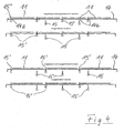
- FIG. 2 shows that the top of the alignment table 14 has a plurality of raster-like distributed over the table surface recesses 14a.
- These recesses have in the top two alternatives of FIG. 2 each in the form of a right angle, one leg of which extends in the longitudinal direction, the other leg in the transverse direction of the Legeticians, whereas in the third alternative shown below of FIG. 2 have a diagonal course.
- each stop 15 are arranged below the recesses 14a, which can be adjusted from a position below the table surface rest position upwards in an active stop position, as in FIG. 4 shown. It can also be seen there that only those stops 15 'are activated which match the dimensions and positions of the veneers placed on the alignment table. In the case of the narrow sides of the veneers, often only one stop needs to be activated; in the case of the long sides, at least two stops should be activated in each case.
- FIG. 2 In each case, a row of veneers 11 is shown in dash-dotted lines, in the coarse alignment, as the veneers are transferred from the drawing strip 13 to the alignment table 14.
- the alignment first in the direction of arrow 1 and then in the direction of arrow 2 - in the below drawn alternative only in the diagonal direction - moved.
- the stops are suitably mounted rotatably about their vertical axis, in order to favor the alignment.
- the veneers are removed together by vacuum suction 16 while maintaining their laying pattern from the alignment table, transported to the laying belt 10 and stored there in the correct position, as in FIG. 1 shown. After lifting the veneers from the alignment table, the alignment table returns to its original position.
- the products can be transferred while maintaining their laying pattern via an intermediate transport 17 on a laying belt 19.
- On this laying belt 19 is carried out by means of stops a further alignment of the possibly displaced during transport parts in the predetermined laying pattern and then laying the top veneers 21.
- the top veneers 21 are treated as well as the bottom veneers 11, i. several veneer stacks are initially adjacent to each other on a helical roller track 22, where they undergo a coarse direction. From there, the uppermost layer of stacked veneer sheets is withdrawn through a vacuum belt 23 and placed on an alignment table 24.
- the alignment table 24 has the same structure as the alignment table 14.
- the cover veneers 21 are brought into their desired position by individual activation of the stops located below the alignment table and by subsequent displacement of the table relative to the stops, as was previously the case with the lower veneers 11 has been described.
- a vacuum suction frame 18 then conveys the aligned veneer row from the alignment table 24 to the laying belt 19 and places it precisely on the products available there, ie on the support plates 3 already provided with a respective lower veneer 11.
- FIG. 1 shows an intermediate stage in collecting.
- the complete package is then transported in its entirety by the collecting belts 20 in the press 25.
- the bottom and top veneers are connected under pressure and heat with their respective support plates.
- FIG. 4 shows the alignment table 14 with differently activated stops. While four lower veneers 11 are next to each other in the upper part and consequently four stops 15 'are raised, the lower half of FIG. 4 larger veneers, of which only three pieces fit next to each other in the press and on the alignment table 14.
- the edge-side projection 15 '(on the left edge of the alignment table 14) remains active, whereas the other stops, which in the upper embodiment for aligning The three remaining lower veneers served, now remain in the lower rest position and for the other two attacks moved into the upper stop position.
- the recesses 14a are shown in the embodiment narrow and slit-like. Of course, it would instead also be possible to provide larger recesses, such that a perforated plate or grid plate is formed as a support surface for the products. All that matters is that between the stops and the table a relative movement is possible whose length and direction is sufficient to align the overlying products to the desired position.
- the alignment table according to the invention can align different sized and differently positioned workpieces with high accuracy.
- the alignment table allows several rows of workpieces to be aligned simultaneously, thereby making better use of the plant's capacity.
Abstract
Description
Die Erfindung betrifft eine Vorrichtung und ein Verfahren zur Herstellung furnierter Platten.The invention relates to an apparatus and a method for producing veneered panels.
Unter dem Begriff "Furnier" werden in der vorliegenden Anmeldung sowohl Holzfurniere als auch Dekorfolien, Gegenzugpapiere und dergleichen verstanden.The term "veneer" in the present application, both wood veneers and decorative films, Gegenzugpapiere and the like understood.
Durch die
Außerdem ist durch die
Vergleichbar ist außerdem noch die
Der vorliegenden Erfindung liegt folgende Problematik zugrunde: Die Furniere werden üblicherweise in Form eines Stapels bereit gesteift, wobei jeweils das oberste Furnier separiert und zur Furnierstation transportiert werden muss. Die Furniere, deren Abmessungen nur geringfügig größer sind als diejenigen der zu beschichtenden Trägerplatten, also der Möbelteile, sind mit einer Genauigkeit von etwa +/- 5 mm Seitenversatz aufgestapelt. Sie werden daher auch mit dieser Toleranz der Furnierstation zugeführt.The present invention is based on the following problems: The veneers are usually prepared ready in the form of a stack, wherein in each case the uppermost veneer has to be separated and transported to the veneer station. The veneers whose dimensions are only slightly larger than those of the carrier plates to be coated, ie the furniture parts are stacked with an accuracy of about +/- 5 mm lateral offset. They are therefore also supplied with this tolerance of the veneer station.
Mit der vorliegenden Erfindung soll nun eine genauere Positionierung der Furniere - alternativ auch der Trägerplatten - erreicht werden, damit der Überstand der Furniere über die Trägerplatte geringer als bisher möglich gewählt werden kann.With the present invention, a more precise positioning of the veneers - alternatively also the support plates - is now to be achieved, so that the supernatant of the veneers on the support plate can be chosen less than previously possible.
Gleichzeitig soll die vorliegende Erfindung eine höhere Kapazitätsausnutzung der Furnierpresse gestatten, indem eine Vielzahl kleiner Platten gleichzeitig in der Presse furniert werden kann.At the same time, the present invention is intended to allow a higher capacity utilization of the veneer press by allowing a plurality of small plates to be simultaneously veneered in the press.
Diese Aufgabe wird hinsichtlich der Vorrichtungsmerkmale erfindungsgemäß durch die Merkmale des Anspruches 1 gelöst.This object is achieved with respect to the device features according to the invention by the features of
Hierdurch ergibt sich der Vorteil, dass eine Vielzahl von Furnieren, alternativ aber auch von Trägerplatten, gleichzeitig sehr genau ausgerichtet werden können. Es ist also eine Vollbelegung der Presse möglich, weil nicht nur die am Rand liegenden Teile ausgerichtet werden, sondern auch im mittleren Pressenbereich Teile gelegt und ausgerichtet werden können. Man kann dadurch die maximale Pressenbreite bzw. -länge ausnutzen. Die Zykluszeit der Presse bleibt dabei unverändert, weil es keine Rolle spielt, ob die Presse nur wenige Teile an den Längsseiten presst oder ob sie voll belegt ist.This results in the advantage that a large number of veneers, but alternatively also of carrier plates, can be aligned very precisely at the same time. So it is a full occupancy of the press possible because not only the parts lying on the edge are aligned, but also in the middle press area parts can be placed and aligned. You can thereby exploit the maximum press width or length. The cycle time of the press remains unchanged, because it does not matter if the press presses only a few parts on the long sides or if it is fully occupied.
Die konstruktive Ausbildung der rasterähnlich über der Tischfläche verteilten Anschläge erfolgt in der Weise, dass sie aus einer inaktiven Ruhestellung unterhalb oder mit Abstand oberhalb der Tischfläche in eine aktive Anschlagposition verstellbar sind, in der sie mit den Längs- und/oder Querrändern der Furniere oder der Trägerplatten in Anlage kommen. Dabei werden nur diejenige Anschläge aktiviert, die an den Längs- oder Querrändern der Furniere oder Trägerplatten liegen, während die übrigen Anschläge in ihrer Ruhestellung bleiben. Die Selektion der zu aktivierenden Anschläge kann automatisch aufgrund des vorgegebenen Legemusters erfolgen. Dieses Legemuster kann entweder einprogrammiert werden oder, falls die Trägerplatten bereits in einem Legemuster bereit liegen, durch eine Kamera erfasst und an die Steuerung der Anschläge weitergegeben werden. - In der Praxis werden die Teileabmessungen in die Steuerung eingegeben. Aus dieser Eingabe errechnet die Steuerung, wie viele Teile längs und quer in die Presse passen und wie die Teile am Besten arrangiert, also in der zur Verfügung stehenden Pressfläche verteilt werden. Die Steuerung aktiviert dann die entsprechenden Anschläge; gleichzeitig kann sie auch den hydraulischen Druck für die einzelnen Presszylinder der Presse errechnen.The constructive design of the grid-like distributed over the table surface attacks done in such a way that they are adjustable from an inactive rest position below or at a distance above the table surface in an active stop position in which they with the longitudinal and / or transverse edges of the veneers or the Carrier plates come into contact. Only the one becomes Activated stops, which lie on the longitudinal or transverse edges of the veneers or support plates, while the remaining stops remain in their rest position. The selection of the attacks to be activated can take place automatically on the basis of the given laying pattern. This laying pattern can either be programmed in or, if the carrier plates are already in a laying pattern ready to be detected by a camera and passed to the control of the attacks. - In practice, the part dimensions are entered into the controller. From this input, the controller calculates how many parts fit longitudinally and transversely into the press and how the parts are best arranged, ie distributed in the available pressing surface. The controller then activates the corresponding stops; At the same time, it can also calculate the hydraulic pressure for the individual press cylinders of the press.
Zweckmäßigerweise sind die Anschläge unterhalb der Tischfläche gelagert und die Tischfläche weist eine Vielzahl von Öffnungen auf, durch welche die Anschläge in ihre aktive Anschlagposition nach oben verstellt werden können.Conveniently, the stops are mounted below the table surface and the table surface has a plurality of openings through which the stops can be adjusted to their active stop position upwards.
Hinsichtlich des Verfahrens wird die Aufgabe durch die Merkmale des Anspruches 7 gelöst. Dadurch werden die aufliegenden Teile zuverlässig ausgerichtet, d.h. in ihre Sollposition verschoben.With regard to the method, the object is achieved by the features of
Vorzugsweise wird die Relativbewegung durch eine Verschiebung der Tischfläche erzeugt, so dass die Anschläge mitsamt ihrer Lagerung und ihrer Aktivierungsmechanik ortsfest bleiben können. Hierfür sind die Öffnungen, die das individuelle Hochfahren der zu aktivierenden Anschläge gestatten, schlitzähnlich in Richtung der genannten Relativbewegung angeordnet.Preferably, the relative movement is generated by a displacement of the table surface, so that the attacks can remain stationary together with their storage and their activation mechanism. For this purpose, the openings that allow the individual startup of the attacks to be activated, slit-like arranged in the direction of said relative movement.
Grundsätzlich bestehen diverse Möglichkeiten, um die Relativbewegung zwischen der Tischfläche und den Anschlägen zu realisieren. Meist ist es am günstigsten, die Bewegung in Längs- und Querrichtung aufzuteilen, wobei sich jedoch beide Bewegungen durchaus überlagern können. Zweckmäßig wird mit der Ausrichtung an den Schmalseiten der Teile begonnen und anschließend werden die Längsseiten gegen die aktivierten Anschläge gedrückt. Es liegt aber durchaus im Rahmen der Erfindung, die Relativbewegung in einer gegenüber Längs- und Querrichtung schrägen Richtung zu realisieren.Basically, there are various possibilities to realize the relative movement between the table surface and the attacks. In most cases, it is best to divide the movement in the longitudinal and transverse directions, but both movements can overlap quite well. Appropriately, the alignment on the narrow sides of the parts is started and then the long sides are pressed against the activated stops. However, it is well within the scope of the invention to realize the relative movement in a direction oblique to the longitudinal and transverse directions.
Gemäß einer besonders vorteilhaften Weiterbildung wird der erfindungsgemäße Ausrichtvorgang auf die Furniere beschränkt, wogegen die Trägerplatten in herkömmlicher Weise während ihres Transportes oder während der Übergabe ausgerichtet werden. Dies hat den Vorteil, dass die Relativbewegung für den Ausrichtvorgang wesentlich schneller stattfinden kann, weil die Furniere bedeutend leichter sind als die Trägerplatten.According to a particularly advantageous development of the alignment process according to the invention is limited to the veneers, whereas the support plates are aligned in a conventional manner during their transport or during the transfer. This has the advantage that the relative movement for the alignment process can take place much faster because the veneers are significantly lighter than the carrier plates.
In diesem Zusammenhang kann es zweckmäßig sein, den Ausrichttisch an ein Unterdruck-System anzuschließen, damit die Furniere an die Tischfläche angesaugt werden und nicht ungewollt verrutschen können.In this context, it may be appropriate to connect the alignment table to a vacuum system so that the veneers are sucked to the table surface and can not accidentally slip.
Weitere Merkmale und Vorteile der Erfindung ergeben sich aus den Unteransprüchen, aus der nachfolgenden Beschreibung eines Ausführungsbeispiels und aus der Zeichnung. Dabei zeigt
Figur 1- eine schematische Ansicht von oben auf die Furnieranlage;
Figur 2- eine Ansicht von oben auf den Ausrichttisch mit nicht ausgerichteten Furnieren;
Figur 3- die gleiche Ansicht wie
Figur 2 - Figur 4
- einen Vertikalschnitt durch die Tischfläche des Ausrichttisches bei unterschiedlicher Belegung.
- FIG. 1
- a schematic view from above of the veneer plant;
- FIG. 2
- a top view of the alignment table with non-aligned veneers;
- FIG. 3
- the same view as
FIG. 2 but after alignment of the veneers; - FIG. 4
- a vertical section through the table surface of the alignment table with different occupancy.
Die gezeigte Furnieranlage beginnt mit einer Transportbahn 1, die über beidseits angeordnete Beschickvorrichtungen 2 mit Trägerplatten 3 belegt wird. Die Transportbahn 1 ist in Form einer Ausrichtrollenbahn realisiert, so dass die benachbarten Trägerplatten 3 entlang einem in Transportrichtung verlaufenden Anschlag 4 fluchtend ausgerichtet werden. Sodann passieren die Trägerplatten eine Bürstmaschine 5 und eine Leimauftragmaschine 6. Die unterseitig und oberseitig beleimten Trägerplatten können dann auf einer Messerscheibenbahn 7 gepuffert werden, bevor sie auf einer weiteren Messerscheibenbahn 8 durch Anschläge in Längsrichtung, also in Transportrichtung in bestimmte Sollpositionen gebracht werden. Die Trägerplatten 3 liegen dabei in einer Reihe fluchtend hintereinander mit vorgegebenem Abstand, wobei die Positionierung so gewählt wird, dass man die Breite der Beschichtungspresse, wo später das Furnieren stattfindet, gut ausnützt.The veneer system shown begins with a
Anschließend befördert eine Umsetzeinrichtung 9 die gesamte auf der Messerscheibenbahn 8 liegende Produktreihe - quer zur Transportrichtung der Messerscheibenbahn 8 - auf ein Legeband 10, genauer gesagt auf dort bereits zuvor abgelegte Unterfurniere 11. Diese Unterfurniere liegen dort mit dem gleichen Legemuster nebeneinander, wie die Trägerplatten 3 auf der Messerscheibenbahn 8, so dass die Trägerplatten lagegetreu auf die Unterfurniere 11 aufgelegt werden können.Subsequently, a transfer device 9 transports the entire product row lying on the knife disk web 8 - transverse to the transport direction of the knife disk web 8 - onto a
Das Ausrichten und Positionieren der Unterfurniere 11 wird im folgenden näher beschrieben:The alignment and positioning of the
Man erkennt seitlich neben dem Legeband 10 eine Schrägrollenbahn 12, auf der mehrere Stapel mit Unterfurnieren 11 liegen. Diese Furnierstapel sind zwar an einer längs zur Transportrichtung der Schrägrollenbahn verlaufenden Anschlagleiste und in Querrichtung durch Anschläge ausgerichtet; dabei handelt es sich aber um eine Grobausrichtung, weil die Furniere innerhalb ihres jeweiligen Stapels nicht genau übereinander liegen. Zur genaueren Ausrichtung wird die oberste Lage einer Reihe der Furniere mittels einer Vakuumziehleiste 13 aus dem jeweiligen Furnierstapel abgenommen und auf einem Ausrichttisch 14 abgelegt. Dort erfolgt das genaue Ausrichten und Positionieren der Furniere.It can be seen laterally next to the laying
Nähere Einzelheiten zu dem Ausrichttisch ergeben sich aus den folgenden Figuren.Further details of the alignment table will be apparent from the following figures.
Wesentlich ist nun, dass unterhalb der Ausnehmungen 14a jeweils Anschläge 15 angeordnet sind, die aus einer unterhalb der Tischfläche befindlichen Ruheposition nach oben in eine aktive Anschlagposition verstellt werden können, wie in
In
So lange das gleiche Plattenformat gefahren wird, können die Anschläge 15' in ihrer oberen Aktionsstellung bleiben.As long as the same plate format is driven, the stops 15 'can remain in their upper action position.
Sodann werden die Furniere gemeinsam durch Vakuumsauger 16 unter Beibehaltung ihres Legemusters vom Ausrichttisch abgenommen, auf das Legeband 10 transportiert und dort positionsgerecht abgelegt, wie in
Nach dem Auflegen der beleimten Trägerplatten 3 auf die Unterfurniere 11 können die Produkte unter Beibehaltung ihres Legemusters über einen Zwischentransport 17 auf ein Legeband 19 übergeben werden. Auf diesem Legeband 19 erfolgt mittels Anschlägen eine weitere Ausrichtung der eventuell beim Transport verschobenen Teile in das vorgegebene Legemuster und danach das Auflegen der Deckfurniere 21. Die Deckfurniere 21 werden ebenso behandelt wie die Unterfurniere 11, d.h. mehrere Furnierstapel liegen zunächst nebeneinander auf einer Schrägrollenbahn 22, wobei sie eine Grobausrichtung erfahren. Von dort wird die oberste Lage von gestapelten Furnierblättern durch eine Vakuumziehleiste 23 abgezogen und auf einen Ausrichttisch 24 gelegt.After placing the glued
Der Ausrichttisch 24 hat den gleichen Aufbau wie der Ausrichttisch 14. Auf ihm werden also die Deckfurniere 21 durch individuelle Aktivierung der unter dem Ausrichttisch befindlichen Anschläge und durch anschließende Verschiebung des Tisches relativ zu den Anschlägen in ihre Sollposition gebracht, wie dies zuvor bei den Unterfurnieren 11 beschrieben worden ist. Ein Vakuumsaugrahmen 18 befördert dann die ausgerichtete Furnierreihe vom Ausrichttisch 24 zu dem Legeband 19 und legt sie passgenau auf die dort bereitstehenden Produkte, also auf die bereits mit jeweils einen Unterfurnier 11 versehenen Trägerplatten 3 auf.The alignment table 24 has the same structure as the alignment table 14. Thus, the cover veneers 21 are brought into their desired position by individual activation of the stops located below the alignment table and by subsequent displacement of the table relative to the stops, as was previously the case with the
Anschließend werden die Produkte auf Sammelbändern 20 in mehreren Reihen hintereinander arrangiert, und zwar so viele Reihen hintereinander, wie in die Presse hinein passen.
Die gleiche individuelle Ansteuerung der Anschläge ergibt sich auch senkrecht zur Zeichnungsebene entsprechend der Abmessungen der Furniere in dieser Richtung.The same individual control of the attacks also results perpendicular to the plane of the drawing according to the dimensions of the veneers in this direction.
Das Verstellen der Anschläge zwischen ihrer unteren Ruheposition und ihrer oberen Aktivposition erfolgt zweckmäßig durch Druckluftzylinder; ebenso wären aber auch Hubmagnete oder andere Antriebe möglich.The adjustment of the stops between their lower rest position and their upper active position is advantageously carried out by compressed air cylinder; but also solenoids or other drives would be possible.
Die Ausnehmungen 14a sind im Ausführungsbeispiel schmal und schlitzartig abgebildet. Selbstverständlich wäre es stattdessen auch möglich, größere Ausnehmungen vorzusehen, derart, dass eine Lochplatte oder Gitterplatte als Auflagefläche für die Produkte entsteht. Entscheidend ist lediglich, dass zwischen den Anschlägen und dem Tisch eine Relativbewegung möglich ist, deren Länge und Richtung ausreicht, um die aufliegenden Produkte auf die Sollposition auszurichten.The
Auch liegt es im Rahmen der Erfindung, nicht immer nur eine Reihe von Trägerplatten und Furnieren auf den jeweiligen Legebändern bereit zu stellen, sondern mehrere nebeneinander liegenden Reihen. Dazu brauchen lediglich die Vakuumsaugrahmen 16 und 18 mit zusätzlichen Saugern ergänzt zu werden. Die Übergabe der Trägerplatten 3 kann in der beschriebenen Weise beibehalten werden, wenn man mehrere Reihen hintereinander auf dem Legeband 10 ablegt. Stattdessen könnten aber natürlich auch gleich mehrere Reihen von Trägerplatten gemeinsam durch eine entsprechend umgestaltete Fördereinrichtung auf das Legeband 10 transportiert werden.It is also within the scope of the invention to provide not always only a number of carrier plates and veneers on the respective levers, but several adjacent rows. For this purpose, only the
Ebenso liegt es im Rahmen der Erfindung, die beschriebenen Ausrichttische nicht nur für das Ausrichten der Furniere, sondern auch für das Ausrichten der Trägerplatten einzusetzen.It is also within the scope of the invention to use the alignment tables described not only for the alignment of the veneers, but also for the alignment of the carrier plates.
Zusammenfassend besteht bei allen Ausführungsvarianten der Vorteil, dass der erfindungsgemäße Ausrichttisch unterschiedlich große und auch unterschiedlich positionierte Werkstücke hochgenau ausrichten kann. Vor allem gestattet es der Ausrichttisch, mehrere Reihen von Werkstücken gleichzeitig auszurichten und dadurch die Kapazität der Anlage besser auszunützen.In summary, in all embodiments, the advantage that the alignment table according to the invention can align different sized and differently positioned workpieces with high accuracy. Above all, the alignment table allows several rows of workpieces to be aligned simultaneously, thereby making better use of the plant's capacity.
Claims (12)
- Apparatus for producing veneered panels with a veneering station and a veneering press, wherein supporting panels (3) glued on at least one side and the appertaining veneers (11, 21) are transported into the veneering station and are placed on one another in alignment with one another and then are veneered on at least one side in the veneering press (25), wherein the alignment takes place on an aligning table (14, 24) by means of adjustable stops (15) which are distributed in a grid over the table surface and can be activated individually according to a predetermined laying pattern, wherein the stops (15) can be moved out of an inactive rest position below or above the table surface into an active stop position (15') in which they come into contact with the longitudinal and transverse edges of the veneers (11, 21) or supporting panels (3).
- Apparatus as claimed in Claim 1, characterised in that the stops (15) are mounted below the table surface and the table surface has a plurality of openings (14a) for movement of the stops (15) into their active stop position (15').
- Apparatus as claimed in Claim 1, characterised in that at least one approximately horizontal relative movement in the longitudinal and transverse direction - optionally in combination - takes place between the table surface and the stops (15).
- Apparatus as claimed in Claim 3, characterised in that the relative movement is slowed down towards the end position.
- Apparatus as claimed in Claim 2, characterised in that the openings (14a) are disposed like slits in the direction of the relative movement between the table surface and the stops.
- Apparatus as claimed in Claim 1, characterised in that the aligning table (14, 24) can be connected to a vacuum in order to draw on the veneers (11, 21) or supporting panels (3) by suction.
- Method of producing veneered panels, wherein supporting panels (3) glued on at least one side and the appertaining veneers (11, 21) are transported into the veneering station and are placed on one another in alignment with one another and then are veneered on at least one side in a veneering press (25), wherein a plurality of veneers (11, 21) or supporting panels (3) are individually aligned simultaneously on a common aligning table (14, 24) according o a predetermined laying position by means of a plurality of movable stops (15, 15') which are activated according to the predetermined laying pattern and come into contact with the longitudinal and/or transverse edges of the veneers (11, 21) or supporting panels (3), wherein for alignment a relative movement is produced between the aligning table (14, 24) and the stops (15') in the longitudinal and transverse direction, preferably in a diagonal direction, and the alignment takes place in the longitudinal and transverse direction.
- Method as claimed in Claim 7, characterised in that the aligning table (14, 24) moves relative to the stops (15').
- Method as claimed in Claim 7, characterised in that a plurality of veneers (11, 21) or supporting panels (3) are simultaneously aligned with their longitudinal or transverse edges along a common straight line.
- Method as claimed in Claim 7, characterised in that the alignment begins on the narrow sides of the veneers (11, 21) or supporting panels (3).
- Method as claimed in Claim 8, characterised in that first of all the aligned veneers (11, 21) or supporting panels (3) are taken off from the aligning table (14, 24) before the aligning table moves back into its starting position.
- Method as claimed in Claim 7, characterised in that the stops (15, 15') of the veneers (11, 21) or supporting panels (3) can be turned about a vertical axis during alignment.
Priority Applications (1)
| Application Number | Priority Date | Filing Date | Title |
|---|---|---|---|
| PL06011449T PL1749627T3 (en) | 2005-07-27 | 2006-06-02 | Apparatus and method for manufacturing veneer panels |
Applications Claiming Priority (1)
| Application Number | Priority Date | Filing Date | Title |
|---|---|---|---|
| DE102005035804A DE102005035804A1 (en) | 2005-07-27 | 2005-07-27 | Device for producing veneer boards comprises an aligning table for aligning support plates and veneers using stops which are distributed over the table surface |
Publications (2)
| Publication Number | Publication Date |
|---|---|
| EP1749627A1 EP1749627A1 (en) | 2007-02-07 |
| EP1749627B1 true EP1749627B1 (en) | 2008-02-27 |
Family
ID=37401183
Family Applications (1)
| Application Number | Title | Priority Date | Filing Date |
|---|---|---|---|
| EP06011449A Not-in-force EP1749627B1 (en) | 2005-07-27 | 2006-06-02 | Apparatus and method for manufacturing veneer panels |
Country Status (4)
| Country | Link |
|---|---|
| EP (1) | EP1749627B1 (en) |
| AT (1) | ATE387297T1 (en) |
| DE (2) | DE102005035804A1 (en) |
| PL (1) | PL1749627T3 (en) |
Families Citing this family (4)
| Publication number | Priority date | Publication date | Assignee | Title |
|---|---|---|---|---|
| DE102007047517A1 (en) * | 2007-10-04 | 2009-04-09 | Adolf Vietmeyer | Process for producing a veneer sheet from individual strips of real wood veneer and veneer sheet produced by this method |
| CN110524645A (en) * | 2019-09-24 | 2019-12-03 | 徐州安嘉金属制品有限公司 | Glued board pressing device |
| ES2954776T3 (en) * | 2020-04-24 | 2023-11-24 | Flooring Technologies Ltd | Device and procedure for depositing wood veneers |
| DE102021112793A1 (en) | 2021-05-18 | 2022-11-24 | H-Flachs Gmbh | Device and method for manufacturing plate sandwiches |
Family Cites Families (5)
| Publication number | Priority date | Publication date | Assignee | Title |
|---|---|---|---|---|
| DE9200523U1 (en) * | 1992-01-17 | 1992-04-02 | Wm Wild Maschinen Gmbh, 4835 Rietberg, De | |
| DE19832534C1 (en) * | 1998-07-20 | 2000-04-20 | Buerkle Gmbh Robert | Device for transferring glued panels to a veneer station |
| DE10254504B4 (en) * | 2002-11-22 | 2006-02-16 | Tünkers Maschinenbau Gmbh | Method for laminating two or more identical or different sheets, and device for carrying out the method |
| DE10329422B4 (en) * | 2003-07-01 | 2005-04-28 | Mba Automation Gmbh | Veneer application process for final size furniture components involves taking veneer to first and second defined positions and applying it to component |
| DE202004001308U1 (en) * | 2004-01-28 | 2004-04-08 | Mba Automation Gmbh | Device to apply veneer to panels for furniture has panel handling device, magazines for top and bottom veneers, and multiple suction unit to withdraw and move veneers |
-
2005
- 2005-07-27 DE DE102005035804A patent/DE102005035804A1/en not_active Withdrawn
-
2006
- 2006-06-02 EP EP06011449A patent/EP1749627B1/en not_active Not-in-force
- 2006-06-02 DE DE502006000386T patent/DE502006000386D1/en active Active
- 2006-06-02 PL PL06011449T patent/PL1749627T3/en unknown
- 2006-06-02 AT AT06011449T patent/ATE387297T1/en active
Also Published As
| Publication number | Publication date |
|---|---|
| ATE387297T1 (en) | 2008-03-15 |
| EP1749627A1 (en) | 2007-02-07 |
| PL1749627T3 (en) | 2008-07-31 |
| DE102005035804A1 (en) | 2007-02-01 |
| DE502006000386D1 (en) | 2008-04-10 |
Similar Documents
| Publication | Publication Date | Title |
|---|---|---|
| DE102008017420B4 (en) | Working method and device for turning and angular transport of loose stacks of workpieces | |
| WO2005077654A1 (en) | Device and method for producing sandwich panels | |
| DE2547149C3 (en) | Stacking device for loading a multi-stage press | |
| DE2906543A1 (en) | METHOD AND SYSTEM FOR SORTING TABLETOUS GOODS | |
| DE3613315C2 (en) | ||
| EP1749627B1 (en) | Apparatus and method for manufacturing veneer panels | |
| EP0200120B1 (en) | Device for feeding flat work pieces to a plate-separating installation, the work pieces having been placed on an elevating table | |
| WO2005087464A1 (en) | Method and device for joining a sandwich plate batten frame | |
| DE102012102208B4 (en) | Automatic press for transverse gluing of massive lamellar elements | |
| DE3809989C2 (en) | Device for producing a plywood panel | |
| AT396891B (en) | DEVICE FOR LOADING CUTTING SAW SYSTEMS | |
| CH694504A5 (en) | A method for cutting metal sheets to metal strips and cutting device for its implementation. | |
| DE2423845A1 (en) | PROCESS AND EQUIPMENT FOR THE MANUFACTURING OF PANELS COATED WITH DECORATIVE FILMS | |
| EP0489681B1 (en) | Method and apparatus for moving closely juxtaposed stacked strips or panel shaped workpieces on a low friction work support surface | |
| EP3397435A1 (en) | Method and device for laying veneer panels | |
| WO1995035192A1 (en) | Process and device for producing a top layer for ready-use parquet flooring | |
| EP1762353B1 (en) | Pressing system for laminated profiles | |
| DE2046054B2 (en) | Device for feeding plate blanks | |
| DE2940796A1 (en) | MACHINE FOR COVERING BOXES WITH A CARDBOARD OR FILM CUT | |
| EP3900933B1 (en) | Device and method for depositing veneers | |
| DE102019112627B3 (en) | Method and device for transporting stacks of workpieces | |
| DE2343993C2 (en) | Method and device for the production of multilayer film sheets from layers of different dimensionally stable properties | |
| DE2533369C3 (en) | Method and device for the production of components formed from stacked, etched motif foils | |
| EP3904025A1 (en) | Method for sawing at least one board | |
| DE2255410C3 (en) | Method and device for joining several layers of veneer in the production of multi-layer plywood panels |
Legal Events
| Date | Code | Title | Description |
|---|---|---|---|
| PUAI | Public reference made under article 153(3) epc to a published international application that has entered the european phase |
Free format text: ORIGINAL CODE: 0009012 |
|
| AK | Designated contracting states |
Kind code of ref document: A1 Designated state(s): AT BE BG CH CY CZ DE DK EE ES FI FR GB GR HU IE IS IT LI LT LU LV MC NL PL PT RO SE SI SK TR |
|
| AX | Request for extension of the european patent |
Extension state: AL BA HR MK YU |
|
| 17P | Request for examination filed |
Effective date: 20070206 |
|
| 17Q | First examination report despatched |
Effective date: 20070315 |
|
| GRAP | Despatch of communication of intention to grant a patent |
Free format text: ORIGINAL CODE: EPIDOSNIGR1 |
|
| AKX | Designation fees paid |
Designated state(s): AT BE BG CH CY CZ DE DK EE ES FI FR GB GR HU IE IS IT LI LT LU LV MC NL PL PT RO SE SI SK TR |
|
| GRAS | Grant fee paid |
Free format text: ORIGINAL CODE: EPIDOSNIGR3 |
|
| GRAA | (expected) grant |
Free format text: ORIGINAL CODE: 0009210 |
|
| AK | Designated contracting states |
Kind code of ref document: B1 Designated state(s): AT BE BG CH CY CZ DE DK EE ES FI FR GB GR HU IE IS IT LI LT LU LV MC NL PL PT RO SE SI SK TR |
|
| REG | Reference to a national code |
Ref country code: GB Ref legal event code: FG4D Free format text: NOT ENGLISH |
|
| REG | Reference to a national code |
Ref country code: CH Ref legal event code: EP |
|
| REG | Reference to a national code |
Ref country code: IE Ref legal event code: FG4D Free format text: LANGUAGE OF EP DOCUMENT: GERMAN |
|
| REF | Corresponds to: |
Ref document number: 502006000386 Country of ref document: DE Date of ref document: 20080410 Kind code of ref document: P |
|
| REG | Reference to a national code |
Ref country code: RO Ref legal event code: EPE |
|
| REG | Reference to a national code |
Ref country code: EE Ref legal event code: FG4A Ref document number: E001955 Country of ref document: EE Effective date: 20080425 |
|
| REG | Reference to a national code |
Ref country code: SE Ref legal event code: TRGR |
|
| PG25 | Lapsed in a contracting state [announced via postgrant information from national office to epo] |
Ref country code: FI Free format text: LAPSE BECAUSE OF FAILURE TO SUBMIT A TRANSLATION OF THE DESCRIPTION OR TO PAY THE FEE WITHIN THE PRESCRIBED TIME-LIMIT Effective date: 20080227 Ref country code: IS Free format text: LAPSE BECAUSE OF FAILURE TO SUBMIT A TRANSLATION OF THE DESCRIPTION OR TO PAY THE FEE WITHIN THE PRESCRIBED TIME-LIMIT Effective date: 20080627 Ref country code: ES Free format text: LAPSE BECAUSE OF FAILURE TO SUBMIT A TRANSLATION OF THE DESCRIPTION OR TO PAY THE FEE WITHIN THE PRESCRIBED TIME-LIMIT Effective date: 20080607 |
|
| REG | Reference to a national code |
Ref country code: PL Ref legal event code: T3 |
|
| NLV1 | Nl: lapsed or annulled due to failure to fulfill the requirements of art. 29p and 29m of the patents act | ||
| PGFP | Annual fee paid to national office [announced via postgrant information from national office to epo] |
Ref country code: RO Payment date: 20080515 Year of fee payment: 3 |
|
| PG25 | Lapsed in a contracting state [announced via postgrant information from national office to epo] |
Ref country code: SI Free format text: LAPSE BECAUSE OF FAILURE TO SUBMIT A TRANSLATION OF THE DESCRIPTION OR TO PAY THE FEE WITHIN THE PRESCRIBED TIME-LIMIT Effective date: 20080227 |
|
| PGFP | Annual fee paid to national office [announced via postgrant information from national office to epo] |
Ref country code: LV Payment date: 20080627 Year of fee payment: 3 Ref country code: LT Payment date: 20080619 Year of fee payment: 3 Ref country code: BG Payment date: 20080623 Year of fee payment: 3 Ref country code: EE Payment date: 20080625 Year of fee payment: 3 |
|
| REG | Reference to a national code |
Ref country code: IE Ref legal event code: FD4D |
|
| PG25 | Lapsed in a contracting state [announced via postgrant information from national office to epo] |
Ref country code: IE Free format text: LAPSE BECAUSE OF FAILURE TO SUBMIT A TRANSLATION OF THE DESCRIPTION OR TO PAY THE FEE WITHIN THE PRESCRIBED TIME-LIMIT Effective date: 20080227 Ref country code: NL Free format text: LAPSE BECAUSE OF FAILURE TO SUBMIT A TRANSLATION OF THE DESCRIPTION OR TO PAY THE FEE WITHIN THE PRESCRIBED TIME-LIMIT Effective date: 20080227 Ref country code: PT Free format text: LAPSE BECAUSE OF FAILURE TO SUBMIT A TRANSLATION OF THE DESCRIPTION OR TO PAY THE FEE WITHIN THE PRESCRIBED TIME-LIMIT Effective date: 20080721 Ref country code: DK Free format text: LAPSE BECAUSE OF FAILURE TO SUBMIT A TRANSLATION OF THE DESCRIPTION OR TO PAY THE FEE WITHIN THE PRESCRIBED TIME-LIMIT Effective date: 20080227 |
|
| PGFP | Annual fee paid to national office [announced via postgrant information from national office to epo] |
Ref country code: SK Payment date: 20080708 Year of fee payment: 7 |
|
| EN | Fr: translation not filed | ||
| BERE | Be: lapsed |
Owner name: ROBERT BURKLE G.M.B.H. Effective date: 20080630 |
|
| PLBE | No opposition filed within time limit |
Free format text: ORIGINAL CODE: 0009261 |
|
| STAA | Information on the status of an ep patent application or granted ep patent |
Free format text: STATUS: NO OPPOSITION FILED WITHIN TIME LIMIT |
|
| PG25 | Lapsed in a contracting state [announced via postgrant information from national office to epo] |
Ref country code: MC Free format text: LAPSE BECAUSE OF NON-PAYMENT OF DUE FEES Effective date: 20080630 |
|
| 26N | No opposition filed |
Effective date: 20081128 |
|
| PG25 | Lapsed in a contracting state [announced via postgrant information from national office to epo] |
Ref country code: BE Free format text: LAPSE BECAUSE OF NON-PAYMENT OF DUE FEES Effective date: 20080630 |
|
| PG25 | Lapsed in a contracting state [announced via postgrant information from national office to epo] |
Ref country code: FR Free format text: LAPSE BECAUSE OF FAILURE TO SUBMIT A TRANSLATION OF THE DESCRIPTION OR TO PAY THE FEE WITHIN THE PRESCRIBED TIME-LIMIT Effective date: 20081219 |
|
| PG25 | Lapsed in a contracting state [announced via postgrant information from national office to epo] |
Ref country code: CY Free format text: LAPSE BECAUSE OF FAILURE TO SUBMIT A TRANSLATION OF THE DESCRIPTION OR TO PAY THE FEE WITHIN THE PRESCRIBED TIME-LIMIT Effective date: 20080227 |
|
| PG25 | Lapsed in a contracting state [announced via postgrant information from national office to epo] |
Ref country code: IT Free format text: LAPSE BECAUSE OF FAILURE TO SUBMIT A TRANSLATION OF THE DESCRIPTION OR TO PAY THE FEE WITHIN THE PRESCRIBED TIME-LIMIT Effective date: 20080227 |
|
| PG25 | Lapsed in a contracting state [announced via postgrant information from national office to epo] |
Ref country code: LT Free format text: LAPSE BECAUSE OF NON-PAYMENT OF DUE FEES Effective date: 20090602 |
|
| REG | Reference to a national code |
Ref country code: EE Ref legal event code: MM4A Ref document number: E001955 Country of ref document: EE Effective date: 20090630 |
|
| PG25 | Lapsed in a contracting state [announced via postgrant information from national office to epo] |
Ref country code: EE Free format text: LAPSE BECAUSE OF NON-PAYMENT OF DUE FEES Effective date: 20090630 |
|
| PG25 | Lapsed in a contracting state [announced via postgrant information from national office to epo] |
Ref country code: LV Free format text: LAPSE BECAUSE OF NON-PAYMENT OF DUE FEES Effective date: 20090603 |
|
| PG25 | Lapsed in a contracting state [announced via postgrant information from national office to epo] |
Ref country code: HU Free format text: LAPSE BECAUSE OF FAILURE TO SUBMIT A TRANSLATION OF THE DESCRIPTION OR TO PAY THE FEE WITHIN THE PRESCRIBED TIME-LIMIT Effective date: 20080828 Ref country code: RO Free format text: LAPSE BECAUSE OF NON-PAYMENT OF DUE FEES Effective date: 20090602 Ref country code: BG Free format text: LAPSE BECAUSE OF FAILURE TO SUBMIT A TRANSLATION OF THE DESCRIPTION OR TO PAY THE FEE WITHIN THE PRESCRIBED TIME-LIMIT Effective date: 20091231 Ref country code: LU Free format text: LAPSE BECAUSE OF NON-PAYMENT OF DUE FEES Effective date: 20080602 |
|
| PG25 | Lapsed in a contracting state [announced via postgrant information from national office to epo] |
Ref country code: TR Free format text: LAPSE BECAUSE OF FAILURE TO SUBMIT A TRANSLATION OF THE DESCRIPTION OR TO PAY THE FEE WITHIN THE PRESCRIBED TIME-LIMIT Effective date: 20080227 |
|
| PG25 | Lapsed in a contracting state [announced via postgrant information from national office to epo] |
Ref country code: GR Free format text: LAPSE BECAUSE OF FAILURE TO SUBMIT A TRANSLATION OF THE DESCRIPTION OR TO PAY THE FEE WITHIN THE PRESCRIBED TIME-LIMIT Effective date: 20080528 |
|
| REG | Reference to a national code |
Ref country code: CH Ref legal event code: PL |
|
| GBPC | Gb: european patent ceased through non-payment of renewal fee |
Effective date: 20100602 |
|
| PG25 | Lapsed in a contracting state [announced via postgrant information from national office to epo] |
Ref country code: CH Free format text: LAPSE BECAUSE OF NON-PAYMENT OF DUE FEES Effective date: 20080630 Ref country code: LI Free format text: LAPSE BECAUSE OF NON-PAYMENT OF DUE FEES Effective date: 20080630 |
|
| PG25 | Lapsed in a contracting state [announced via postgrant information from national office to epo] |
Ref country code: CH Free format text: LAPSE BECAUSE OF NON-PAYMENT OF DUE FEES Effective date: 20100630 Ref country code: LI Free format text: LAPSE BECAUSE OF NON-PAYMENT OF DUE FEES Effective date: 20100630 |
|
| PG25 | Lapsed in a contracting state [announced via postgrant information from national office to epo] |
Ref country code: GB Free format text: LAPSE BECAUSE OF NON-PAYMENT OF DUE FEES Effective date: 20100602 |
|
| PGFP | Annual fee paid to national office [announced via postgrant information from national office to epo] |
Ref country code: CZ Payment date: 20120523 Year of fee payment: 7 |
|
| PGFP | Annual fee paid to national office [announced via postgrant information from national office to epo] |
Ref country code: PL Payment date: 20120523 Year of fee payment: 7 Ref country code: SE Payment date: 20120625 Year of fee payment: 7 |
|
| PGFP | Annual fee paid to national office [announced via postgrant information from national office to epo] |
Ref country code: DE Payment date: 20120628 Year of fee payment: 7 |
|
| PGFP | Annual fee paid to national office [announced via postgrant information from national office to epo] |
Ref country code: AT Payment date: 20120620 Year of fee payment: 7 |
|
| PG25 | Lapsed in a contracting state [announced via postgrant information from national office to epo] |
Ref country code: CZ Free format text: LAPSE BECAUSE OF NON-PAYMENT OF DUE FEES Effective date: 20130602 Ref country code: SE Free format text: LAPSE BECAUSE OF NON-PAYMENT OF DUE FEES Effective date: 20130603 |
|
| REG | Reference to a national code |
Ref country code: SE Ref legal event code: EUG |
|
| REG | Reference to a national code |
Ref country code: AT Ref legal event code: MM01 Ref document number: 387297 Country of ref document: AT Kind code of ref document: T Effective date: 20130602 |
|
| REG | Reference to a national code |
Ref country code: SK Ref legal event code: MM4A Ref document number: E 3504 Country of ref document: SK Effective date: 20130602 |
|
| REG | Reference to a national code |
Ref country code: DE Ref legal event code: R119 Ref document number: 502006000386 Country of ref document: DE Effective date: 20140101 |
|
| PG25 | Lapsed in a contracting state [announced via postgrant information from national office to epo] |
Ref country code: SK Free format text: LAPSE BECAUSE OF NON-PAYMENT OF DUE FEES Effective date: 20130602 Ref country code: DE Free format text: LAPSE BECAUSE OF NON-PAYMENT OF DUE FEES Effective date: 20140101 |
|
| PG25 | Lapsed in a contracting state [announced via postgrant information from national office to epo] |
Ref country code: AT Free format text: LAPSE BECAUSE OF NON-PAYMENT OF DUE FEES Effective date: 20130602 |
|
| REG | Reference to a national code |
Ref country code: PL Ref legal event code: LAPE |
|
| PG25 | Lapsed in a contracting state [announced via postgrant information from national office to epo] |
Ref country code: PL Free format text: LAPSE BECAUSE OF NON-PAYMENT OF DUE FEES Effective date: 20130602 |