EP1747764A2 - Tragevorrichtung für einen Monitor zur Verwendung in einer diagnostischen Ultraschallvorrichtung - Google Patents
Tragevorrichtung für einen Monitor zur Verwendung in einer diagnostischen Ultraschallvorrichtung Download PDFInfo
- Publication number
- EP1747764A2 EP1747764A2 EP06004888A EP06004888A EP1747764A2 EP 1747764 A2 EP1747764 A2 EP 1747764A2 EP 06004888 A EP06004888 A EP 06004888A EP 06004888 A EP06004888 A EP 06004888A EP 1747764 A2 EP1747764 A2 EP 1747764A2
- Authority
- EP
- European Patent Office
- Prior art keywords
- arms
- monitor
- brackets
- supporting device
- connecting member
- Prior art date
- Legal status (The legal status is an assumption and is not a legal conclusion. Google has not performed a legal analysis and makes no representation as to the accuracy of the status listed.)
- Withdrawn
Links
Images




Classifications
-
- F—MECHANICAL ENGINEERING; LIGHTING; HEATING; WEAPONS; BLASTING
- F16—ENGINEERING ELEMENTS AND UNITS; GENERAL MEASURES FOR PRODUCING AND MAINTAINING EFFECTIVE FUNCTIONING OF MACHINES OR INSTALLATIONS; THERMAL INSULATION IN GENERAL
- F16M—FRAMES, CASINGS OR BEDS OF ENGINES, MACHINES OR APPARATUS, NOT SPECIFIC TO ENGINES, MACHINES OR APPARATUS PROVIDED FOR ELSEWHERE; STANDS; SUPPORTS
- F16M13/00—Other supports for positioning apparatus or articles; Means for steadying hand-held apparatus or articles
- F16M13/02—Other supports for positioning apparatus or articles; Means for steadying hand-held apparatus or articles for supporting on, or attaching to, an object, e.g. tree, gate, window-frame, cycle
-
- A—HUMAN NECESSITIES
- A61—MEDICAL OR VETERINARY SCIENCE; HYGIENE
- A61B—DIAGNOSIS; SURGERY; IDENTIFICATION
- A61B90/00—Instruments, implements or accessories specially adapted for surgery or diagnosis and not covered by any of the groups A61B1/00 - A61B50/00, e.g. for luxation treatment or for protecting wound edges
- A61B90/50—Supports for surgical instruments, e.g. articulated arms
-
- F—MECHANICAL ENGINEERING; LIGHTING; HEATING; WEAPONS; BLASTING
- F16—ENGINEERING ELEMENTS AND UNITS; GENERAL MEASURES FOR PRODUCING AND MAINTAINING EFFECTIVE FUNCTIONING OF MACHINES OR INSTALLATIONS; THERMAL INSULATION IN GENERAL
- F16M—FRAMES, CASINGS OR BEDS OF ENGINES, MACHINES OR APPARATUS, NOT SPECIFIC TO ENGINES, MACHINES OR APPARATUS PROVIDED FOR ELSEWHERE; STANDS; SUPPORTS
- F16M11/00—Stands or trestles as supports for apparatus or articles placed thereon ; Stands for scientific apparatus such as gravitational force meters
- F16M11/02—Heads
- F16M11/04—Means for attachment of apparatus; Means allowing adjustment of the apparatus relatively to the stand
- F16M11/06—Means for attachment of apparatus; Means allowing adjustment of the apparatus relatively to the stand allowing pivoting
- F16M11/10—Means for attachment of apparatus; Means allowing adjustment of the apparatus relatively to the stand allowing pivoting around a horizontal axis
-
- F—MECHANICAL ENGINEERING; LIGHTING; HEATING; WEAPONS; BLASTING
- F16—ENGINEERING ELEMENTS AND UNITS; GENERAL MEASURES FOR PRODUCING AND MAINTAINING EFFECTIVE FUNCTIONING OF MACHINES OR INSTALLATIONS; THERMAL INSULATION IN GENERAL
- F16M—FRAMES, CASINGS OR BEDS OF ENGINES, MACHINES OR APPARATUS, NOT SPECIFIC TO ENGINES, MACHINES OR APPARATUS PROVIDED FOR ELSEWHERE; STANDS; SUPPORTS
- F16M11/00—Stands or trestles as supports for apparatus or articles placed thereon ; Stands for scientific apparatus such as gravitational force meters
- F16M11/20—Undercarriages with or without wheels
- F16M11/2007—Undercarriages with or without wheels comprising means allowing pivoting adjustment
- F16M11/2035—Undercarriages with or without wheels comprising means allowing pivoting adjustment in more than one direction
- F16M11/2064—Undercarriages with or without wheels comprising means allowing pivoting adjustment in more than one direction for tilting and panning
-
- A—HUMAN NECESSITIES
- A61—MEDICAL OR VETERINARY SCIENCE; HYGIENE
- A61B—DIAGNOSIS; SURGERY; IDENTIFICATION
- A61B8/00—Diagnosis using ultrasonic, sonic or infrasonic waves
-
- Y—GENERAL TAGGING OF NEW TECHNOLOGICAL DEVELOPMENTS; GENERAL TAGGING OF CROSS-SECTIONAL TECHNOLOGIES SPANNING OVER SEVERAL SECTIONS OF THE IPC; TECHNICAL SUBJECTS COVERED BY FORMER USPC CROSS-REFERENCE ART COLLECTIONS [XRACs] AND DIGESTS
- Y10—TECHNICAL SUBJECTS COVERED BY FORMER USPC
- Y10S—TECHNICAL SUBJECTS COVERED BY FORMER USPC CROSS-REFERENCE ART COLLECTIONS [XRACs] AND DIGESTS
- Y10S248/00—Supports
- Y10S248/917—Video display screen support
Definitions
- the present invention generally relates to a supporting device for a monitor, and more particularly to a supporting device for a monitor for use in an ultrasonic diagnostic apparatus.
- An ultrasonic diagnostic apparatus is a medical equipment for obtaining an ultrasound image of a target region in an object so as to provide clinical information of the target region, such as lesion or neoplasm information of internal organs, fetus information and the like.
- Fig. 1 shows a general ultrasonic diagnostic apparatus.
- An ultrasonic diagnostic apparatus 10 comprises the following: a main body 11; a probe 13 for radiating an ultrasonic wave to a target region and receiving an echo signal reflected from the target region; a control panel 12 for operating the apparatus; and a monitor 14 for displaying ultrasound images.
- a main body 11 for radiating an ultrasonic wave to a target region and receiving an echo signal reflected from the target region
- a control panel 12 for operating the apparatus
- a monitor 14 for displaying ultrasound images.
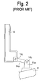
- FIG. 2 A conventional structure for connecting the monitor 14 to the main body 11 in the ultrasonic diagnostic apparatus 10 is illustrated in Fig. 2.
- a base bracket 11a is fixed to the main body 11 and a connecting bar 14a is coupled pivotally to the base bracket 11a by means of a hinge pin 14b at one end.
- the monitor 14 is coupled pivotally to the other end of the connecting bar 14a by means of a hinge pin 14c.
- the monitor 14 can be displaced in a desired position by pivoting the monitor 14 upward or downward in relation to two hinge pins 14b and 14c. This is so that the user can conveniently inspect the ultrasound image displayed on the monitor 14 in accordance with her or his posture.
- the monitor 14 After adjusting the position of the monitor 14, the monitor 14 should be kept in the displaced position.
- the monitor supporting elements i.e., the base bracket 11a, the connecting bar 14a and the hinge pins 14b and 14c, are engaged with each other in a close fit manner. This is to prevent the monitor 14 from moving freely to an undesired position.
- the monitor and the supporting device cannot be folded flat.
- the monitor may bump against other objects (e.g., a wall) and become damaged.
- the assembly becomes bulky and will occupy a large space.
- a supporting device for a monitor for use in an ultrasonic diagnostic apparatus which comprises a main body and a monitor installed to the main body for displaying ultrasound images.
- the supporting device comprises the following: a base frame rotatably mounted to the main body; a pair of arms hingedly jointed to the base frame at respective one ends thereof; a connecting member for interlocking the pair of arms, the connecting member being hingedly coupled to the other ends of the pair of arms; brackets for supporting the monitor, the brackets being rotatably connected to the connecting member; and a device for maintaining the monitor stationary at a certain position by providing the arms and the brackets with a force for restraining the arms and the brackets from being rotated with respect to the base frame and the connecting member against a moment due to a weight of the monitor.
- the device for maintaining the monitor stationary includes an elastic pressing member for pressing the arms and the brackets toward the base frame and the connecting member, respectively, to generate a force for restraining the rotation of the arms and the brackets.
- the device for maintaining the monitor stationary further includes a compressing member for compressing the elastic pressing member, whereby as the elastic pressing member is compressed, the resilient restoring force of the pressing member increases the force for restraining the rotation of the arms and the brackets.
- the supporting device further comprises a device for applying a rotational force to the arms with respect to the base frame against the moment due to the weight of the monitor.
- the device for applying the rotational force to the arms is a torsion coil spring.
- the supporting device further comprises a device for restricting the rotating range of the arms with respect to the base frame.
- the device for restricting the rotating range includes a stopper protruding from one of the arms toward the other arm and a shoulder formed at one of the arms near the connecting member.
- a supporting device for a monitor for use in an ultrasonic diagnostic apparatus which comprises a main body and a monitor installed to the main body for displaying ultrasound images.
- the supporting device comprises the following: a base frame rotatably mounted to the main body; a pair of arms hingedly jointed to the base frame at respective one ends thereof by means of hinge shafts; a connecting member for interlocking the pair of arms, the connecting member being hingedly coupled to the other ends of the pair of arms by means of hinge shafts; a supporting shaft coupled to the connecting member; brackets for supporting the monitor, the brackets being rotatably coupled to the supporting shaft; and a device for maintaining the monitor stationary at a certain position by providing the arms and the brackets with a force for restraining the arms and the brackets from being rotated with respect to the base frame and the connecting member against a moment due to a weight of the monitor.
- the device for maintaining the monitor stationary includes a spring washer fitted to the hinge shafts and the supporting shaft for pressing the arms and the brackets toward the base frame and the connecting member, respectively, and a nut coupled to the hinge shafts and the supporting shaft. As the nut is tightened, the spring washer is compressed and the resilient restoring force of the spring washer increases a force for restraining the rotation of the arms and the brackets.
- a torsion coil spring is mounted to the hinge shafts connecting the arms to the base frame.
- the torsion coil spring provides a rotational force to the arms against the moment due to the weight of the monitor.
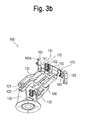
- Figs. 3a and 3b are top and bottom perspective views showing a supporting device for a monitor for use in an ultrasonic diagnostic apparatus constructed in accordance with the present invention, respectively.
- a plate-shaped mounting bracket 111 is fixed to a main body 11 ( see Fig. 1) of an ultrasonic diagnostic apparatus.
- a base frame 120 is rotatably mounted to the mounting bracket 111 on the axis of a rotating shaft 112.
- the base frame 120 has a U-shaped cross-section, which has two opposing side walls.
- a first arm 130 is hingedly jointed to the side walls of the base frame 120 by means of hinge shafts 121 at one end.
- a second arm 140 is disposed under the first arm 130 and is hingedly jointed to the side walls of the base frame 120 by means of hinge shafts 122 at one end.
- Two connecting members 150 are hingedly coupled to the other ends of the first and second arms 130 and 140 by means of hinge shafts 151 and 152, respectively. The other end portions of the arms 130 and 140 are interposed between two connecting members 150.
- Two supporting shafts 161 are respectively mounted to the connecting members 150. Each supporting shaft 161 extends outward in parallel with the hinge shafts 121, 122, 151 and 152.
- a pair of supporting brackets 162 are rotatably mounted to the front end portions of the supporting shafts 161.
- the monitor 14 see Fig. 1) can be fixed to the brackets 162 by fastening screws into a case of the monitor 14 through screw holes 162a of the brackets 162.
- the monitor 14 can be moved in a multiple degree-of-freedom. More specifically, the monitor 14 can be displaced in a direction of double-headed arrow R1 on the axis of the rotating shaft 112, in a direction of double-headed arrow R2 on the axis of the hinge shafts 121 and 122, and in a direction of double-headed arrow R3 on the axis of the supporting shafts 161.
- the supporting device 100 further comprises a device 170 for maintaining the monitor 14 stationary after being displaced to a desired position.
- the device 170 is mounted to the supporting shafts 161 and at least one of the hinge shafts 121, 122, 151 and 152.
- the device 170 prevents the monitor 14 from being undesirably displaced from the position set by the user.
- each of the device 170 for maintaining the monitor 14 stationary includes: flat washer 173 fitted to each shaft 121, 122, 151, 152 and 161; an elastic pressing member 172 fitted to each shaft next to the flat washer 173; and a nut 171 screw-coupled to each shaft next to the elastic pressing member 172.
- the device 170 When the device 170 is applied to the hinge shaft 121 or 122, the device 170 further includes another flat washer 174 fitted to the hinge shaft 121 or 122 such that the flat washer 174 is interposed between the base frame 120 and the first or second arm 130 or 140.
- the flat washer 173 is located on the opposite side of the base frame 120 to the flat washer 174.
- the elastic pressing member 172 may be one of the members capable of applying a pressing force to the flat washer 173 along the axial direction of the shaft. In this embodiment, the elastic pressing member 172 is a spring washer.
- the spring washer 172 is compressively deformed and the resilient restoring force of the spring washer 172 is applied to the flat washer 173 to push the same toward the base frame 120. Because the hinge shaft 121 or 122 is provided with a head portion at one end so as to be prevented from being separated from the first or second arm 130 or 140, the flat washers 173 and 174, the base frame 120 and the first or second arm 130 or 140 are placed in close contact with each other. The more the nut 171 is tightened, the larger the static frictional force between the first or second arm 130 or 140 and the flat washer 174 becomes. Accordingly, in some cases, if the nut 171 is tightened to the maximum, the monitor 14 cannot be displaced, but is fixed at one position.
- the force When the user applies a force to the monitor 14 to change its position, the force produces a torque. If the torque is larger than the static frictional force between the first or second arm 130 or 140 and the flat washer 174, the first or second arm 130 or 140 is rotated about the hinge shaft 121 or 122. After the force is removed from the monitor 14, the moment due to the weight of the monitor 14 is applied to the arms 130 and 140. Therefore, it is preferable that the static frictional force between the first or second arm 130 or 140 and the flat washer 174 is set to be equal to or slightly larger than the moment due to the weight of the monitor 14. This is so that the monitor 14 can be maintained in a stationary position. As described above, the static frictional force can be easily adjusted by the extent to which the nut 171 is tightened.
- the extent of tightening the nut 171 of each hinge shaft will be half of that when the device 170 is mounted to only one hinge shaft.
- the device 170 for maintaining the monitor 14 stationary which includes the flat washer, the elastic pressing member and the nut, may be additionally mounted to the hinge shafts 151 and 152. This is to intensify the static frictional force against the moment due to the weight of the monitor 14.
- the device 170 for maintaining the monitor 14 stationary is also mounted to the supporting shafts 161, to which the supporting brackets 162 are rotatably mounted.
- the static frictional force between the device 170 and the supporting brackets 162 is adjusted so that the supporting brackets 162 are prevented from being undesirably rotated about the supporting shafts 161 by the moment due to the weight of the monitor 14.
- Fig. 5 is an enlarged side view showing an operating state of the supporting device constructed in accordance with the present invention.
- the connecting member 150 is rotated clockwise (as shown by real-line arrows). In such a case, the distance between the first arm 130 and the second arm 140 becomes wider. This rotational operation is not restricted until a contacting surface 150a of the connecting member 150 comes in contact with a shoulder 140a ( see Fig. 3a) of the second arm 140.
- the rotating angle of the first and second arms 130 and 140 with respect to the base frame 120 can be determined in accordance with the shape, the location or the like of the shoulder 140a and the stopper 141.
- the device for restricting the rotational range of the arms 130 and 140 is not limited to the shoulder 140a and the stopper 141, which are illustrated in Fig. 5.
- the supporting device 100 of the present invention further comprises a device for enabling the user to move the monitor 14 upward with a relatively small force. More specifically, when the user intends to move the monitor 14 downward, the user may pull down the monitor 14 with a force equivalent to a difference just between the above-described static frictional force and the moment due to the weight of the monitor 14. However, when the user intends to move the monitor 14 upward, the user should push up the monitor 14 with a larger force against the static frictional force and the moment due to the weight of the monitor 14. In order to relieve the user from this problem, a torsion coil spring 123 is provided at the hinge shaft 121 of the first arm 130. Two end portions of the torsion coil spring 123 extend angle-wise with respect to each other.
- One end portion is placed in a groove (not shown) formed at the first arm 130 in the vicinity of the hinge shaft 121.
- the other end portion is placed in a groove 122a ( see Fig. 4) formed on the peripheral surface of the hinge shaft 122 of the second arm 140.
- Figs. 6 and 7 are side views showing various displacements of the monitor 14.
- the monitor 14 can be moved upward or downward by the rotation of the first and second arms 130 and 140 with respect to the base frame 120.
- the monitor 14 can be rotated about the supporting shaft 161 with respect to the arms 130 and 140.
- the monitor 14 can be rotated with an angle of 180° or more on the axis of the supporting shaft 161, it can be folded flat with the supporting device 100.
- the monitor supporting device enables a user to displace a monitor easily and diversely according to his or her posture by adopting a multi-joint structure, thereby providing convenience in use.
- the force for sustaining the monitor can be simply adjusted merely by tightening or loosening a nut provided at hinge shafts.
- the monitor can be folded flat with the supporting device, the packing and transporting can be facilitated.
Landscapes
- Engineering & Computer Science (AREA)
- General Engineering & Computer Science (AREA)
- Health & Medical Sciences (AREA)
- Life Sciences & Earth Sciences (AREA)
- Mechanical Engineering (AREA)
- Surgery (AREA)
- Public Health (AREA)
- Animal Behavior & Ethology (AREA)
- Veterinary Medicine (AREA)
- Biomedical Technology (AREA)
- Heart & Thoracic Surgery (AREA)
- Medical Informatics (AREA)
- Molecular Biology (AREA)
- Pathology (AREA)
- General Health & Medical Sciences (AREA)
- Nuclear Medicine, Radiotherapy & Molecular Imaging (AREA)
- Oral & Maxillofacial Surgery (AREA)
- Physics & Mathematics (AREA)
- Biophysics (AREA)
- Radiology & Medical Imaging (AREA)
- Ultra Sonic Daignosis Equipment (AREA)
Applications Claiming Priority (1)
| Application Number | Priority Date | Filing Date | Title |
|---|---|---|---|
| KR1020050069258A KR100880123B1 (ko) | 2005-07-29 | 2005-07-29 | 초음파 진단 장치의 모니터를 지지하기 위한 4관절형 모니터 지지 조립체 |
Publications (2)
| Publication Number | Publication Date |
|---|---|
| EP1747764A2 true EP1747764A2 (de) | 2007-01-31 |
| EP1747764A3 EP1747764A3 (de) | 2009-09-30 |
Family
ID=37487740
Family Applications (1)
| Application Number | Title | Priority Date | Filing Date |
|---|---|---|---|
| EP06004888A Withdrawn EP1747764A3 (de) | 2005-07-29 | 2006-03-10 | Tragevorrichtung für einen Monitor zur Verwendung in einer diagnostischen Ultraschallvorrichtung |
Country Status (4)
| Country | Link |
|---|---|
| US (1) | US7448583B2 (de) |
| EP (1) | EP1747764A3 (de) |
| JP (1) | JP2007037981A (de) |
| KR (1) | KR100880123B1 (de) |
Cited By (1)
| Publication number | Priority date | Publication date | Assignee | Title |
|---|---|---|---|---|
| EP2578160A4 (de) * | 2010-05-27 | 2015-11-04 | Hitachi Aloka Medical Ltd | Ultraschalldiagnosevorrichtung |
Families Citing this family (21)
| Publication number | Priority date | Publication date | Assignee | Title |
|---|---|---|---|---|
| US7444716B2 (en) * | 2006-04-25 | 2008-11-04 | Shin Zu Shing Co., Ltd | Dual-axle hinge |
| EP1931131A1 (de) * | 2006-12-04 | 2008-06-11 | Thomson Licensing | Doppelscharnieranzeigevorrichtungsaufhängung |
| JP4841415B2 (ja) * | 2006-12-11 | 2011-12-21 | ジーイー・メディカル・システムズ・グローバル・テクノロジー・カンパニー・エルエルシー | 表示部支持アームおよび超音波撮像装置 |
| CN101452747B (zh) * | 2007-12-07 | 2012-11-21 | 鸿富锦精密工业(深圳)有限公司 | 升降支撑架及其四连杆机构 |
| CN101471144B (zh) * | 2007-12-28 | 2013-06-05 | 鸿富锦精密工业(深圳)有限公司 | 显示装置调整机构 |
| CN101684838B (zh) * | 2008-09-26 | 2012-05-30 | 鸿富锦精密工业(深圳)有限公司 | 铰链结构 |
| KR101076370B1 (ko) | 2009-11-16 | 2011-10-25 | 주식회사 와이드 | 의료영상 판독용 평판 디스플레이 장치의 콘트롤 판넬 장치 |
| US20110184285A1 (en) * | 2010-01-22 | 2011-07-28 | Danli Han | Ultrasonic diagnosis apparatus |
| JP4797110B1 (ja) * | 2010-05-27 | 2011-10-19 | 日立アロカメディカル株式会社 | 超音波診断装置 |
| US9277812B2 (en) | 2010-07-08 | 2016-03-08 | Southco, Inc. | Display support with first and second arms and mechanism for maintaining constant orientation of the plane bisecting the range of rotation of the second arm relative to a support base |
| JP5373830B2 (ja) * | 2011-01-19 | 2013-12-18 | ジーイー・メディカル・システムズ・グローバル・テクノロジー・カンパニー・エルエルシー | 支持アーム及び画像表示装置 |
| TWM458627U (zh) * | 2012-11-26 | 2013-08-01 | Flytech Technology Co Ltd | 端點服務裝置及其可調式連接座 |
| TWM476215U (en) * | 2013-12-20 | 2014-04-11 | Syncmold Entpr Corp | Linkage supporting device |
| EP3875829A3 (de) | 2016-03-07 | 2021-10-13 | Southco, Inc. | Stützarmbaugruppe für eine anzeige zur montage einer anzeige |
| US10330467B2 (en) * | 2016-06-01 | 2019-06-25 | Virtek Vision International Ulc | Precision locating rotary stage |
| KR102635045B1 (ko) * | 2016-07-29 | 2024-02-08 | 삼성메디슨 주식회사 | 초음파 진단 장치 |
| US10995872B1 (en) * | 2017-10-25 | 2021-05-04 | Lyndon J. Hurley | Pivoting support assembly |
| KR102615049B1 (ko) * | 2018-03-07 | 2023-12-19 | 삼성메디슨 주식회사 | 초음파진단장치 |
| KR102551868B1 (ko) | 2020-12-04 | 2023-07-06 | 알피니언메디칼시스템 주식회사 | 로크 부재를 구비한 초음파 진단장치 |
| US12343611B2 (en) * | 2022-02-25 | 2025-07-01 | Equip Products, Inc. | Control panel mount for exercise machine |
| US12467489B2 (en) | 2022-03-17 | 2025-11-11 | Mako Surgical Corp. | Techniques for securing together components of one or more surgical carts |
Family Cites Families (17)
| Publication number | Priority date | Publication date | Assignee | Title |
|---|---|---|---|---|
| JPH0515529A (ja) * | 1991-07-11 | 1993-01-26 | Matsushita Electric Ind Co Ltd | 超音波診断装置のモニタ部保持装置 |
| US5842672A (en) * | 1996-06-07 | 1998-12-01 | Ergotron, Inc. | Mounting system for flat panel display, keyboard and stand |
| US5812368A (en) * | 1997-06-04 | 1998-09-22 | Kuo Feng Corporation | Monitor viewing angle adjusting assembly having monitor mounted on two supporting arm assemblies via turning limit assemblies |
| JP2000330475A (ja) * | 1999-05-24 | 2000-11-30 | Mitsubishi Electric Corp | 車載用表示装置の取付構造 |
| US6347433B1 (en) * | 1999-06-18 | 2002-02-19 | Cema Technologies, Inc. | Flat panel display tilt and swivel mechanism |
| JP2001211943A (ja) * | 2000-02-02 | 2001-08-07 | Matsushita Electric Ind Co Ltd | 昇降式収納装置 |
| JP2001227528A (ja) * | 2000-02-14 | 2001-08-24 | Saint-Gobain Norton Kk | フリーストップヒンジ |
| US6378830B1 (en) * | 2000-10-05 | 2002-04-30 | Lu Sheng-Nan | Adjustable support for an LCD monitor |
| KR200234588Y1 (ko) * | 2001-03-06 | 2001-09-28 | 경일정밀 주식회사 | 엘씨디모니터용 힌지 |
| US7604206B2 (en) * | 2001-11-19 | 2009-10-20 | Samsung Electronics Co., Ltd. | Monitor improved in a tilting and combining structure |
| US6663569B1 (en) * | 2002-05-23 | 2003-12-16 | Koninklijke Philips Electronics N.V. | Diagnostic ultrasound system cart with variable elevation control panel |
| KR100520060B1 (ko) * | 2002-05-28 | 2005-10-11 | 삼성전자주식회사 | 모니터장치 |
| KR100461185B1 (ko) * | 2002-06-07 | 2004-12-13 | 삼성전자주식회사 | 모니터장치 |
| TW537479U (en) * | 2002-08-01 | 2003-06-11 | Bo-Sen Chiou | Rod connecting type ascending and descending device |
| KR100482007B1 (ko) * | 2002-09-28 | 2005-04-13 | 삼성전자주식회사 | 모니터장치 |
| US6769657B1 (en) * | 2003-04-09 | 2004-08-03 | Min Hwa Huang | Support device for monitor, display or objects |
| US6889404B2 (en) * | 2003-07-18 | 2005-05-10 | Shin Zu Shing Co., Ltd. | Height-adjustable hinge for a liquid crystal display |
-
2005
- 2005-07-29 KR KR1020050069258A patent/KR100880123B1/ko not_active Expired - Lifetime
-
2006
- 2006-03-07 US US11/368,476 patent/US7448583B2/en not_active Expired - Lifetime
- 2006-03-10 EP EP06004888A patent/EP1747764A3/de not_active Withdrawn
- 2006-04-06 JP JP2006105199A patent/JP2007037981A/ja active Pending
Cited By (1)
| Publication number | Priority date | Publication date | Assignee | Title |
|---|---|---|---|---|
| EP2578160A4 (de) * | 2010-05-27 | 2015-11-04 | Hitachi Aloka Medical Ltd | Ultraschalldiagnosevorrichtung |
Also Published As
| Publication number | Publication date |
|---|---|
| JP2007037981A (ja) | 2007-02-15 |
| KR100880123B1 (ko) | 2009-01-23 |
| EP1747764A3 (de) | 2009-09-30 |
| KR20070014536A (ko) | 2007-02-01 |
| US20070023598A1 (en) | 2007-02-01 |
| US7448583B2 (en) | 2008-11-11 |
Similar Documents
| Publication | Publication Date | Title |
|---|---|---|
| US7448583B2 (en) | Supporting device for a monitor for use in an ultrasonic diagnostic apparatus | |
| US5052078A (en) | Hinge mechanism for portable electronic apparatus | |
| KR101239979B1 (ko) | 디스플레이장치 | |
| CN100518459C (zh) | 显示设备的支架 | |
| KR101599301B1 (ko) | 전자 기기 | |
| US6912120B2 (en) | Tilting and shielding apparatus of monitor | |
| US7748680B2 (en) | Foldable stand for display device | |
| US10773395B2 (en) | Robot and arm assembly thereof | |
| US10927931B2 (en) | Robot and arm assembly thereof | |
| US20130181104A1 (en) | Flat panel display including a hinge assembly | |
| US20030222187A1 (en) | Adjustable inclined angle structure for computers | |
| US6694569B2 (en) | Hinge device | |
| JP5063313B2 (ja) | 超音波診断装置 | |
| US20060187625A1 (en) | Monitor apparatus | |
| US6859356B2 (en) | Apparatus for supporting a monitor | |
| US20070001084A1 (en) | Swiveling apparatus for a monitor apparatus | |
| JPH10335843A (ja) | バネ部材、ハンドル装置、及び持ち運び可能機器 | |
| KR100949064B1 (ko) | 초음파 진단장치의 모니터 지지장치 | |
| CN101363569A (zh) | 平面粘固式支架 | |
| US9060413B2 (en) | Installation posture adjustable leg body and electronic device including the same | |
| US12383226B2 (en) | Ultrasonic diagnostic device having lock member | |
| JPH0566715A (ja) | フラツトデイスプレイ支持機構 | |
| US12539102B2 (en) | Ultrasound imaging system with improved lock device | |
| US10238567B2 (en) | Arm mechanism | |
| US10486289B2 (en) | Tool with mechanism for wear adjustment |
Legal Events
| Date | Code | Title | Description |
|---|---|---|---|
| PUAI | Public reference made under article 153(3) epc to a published international application that has entered the european phase |
Free format text: ORIGINAL CODE: 0009012 |
|
| AK | Designated contracting states |
Kind code of ref document: A2 Designated state(s): AT BE BG CH CY CZ DE DK EE ES FI FR GB GR HU IE IS IT LI LT LU LV MC NL PL PT RO SE SI SK TR |
|
| AX | Request for extension of the european patent |
Extension state: AL BA HR MK YU |
|
| PUAL | Search report despatched |
Free format text: ORIGINAL CODE: 0009013 |
|
| AK | Designated contracting states |
Kind code of ref document: A3 Designated state(s): AT BE BG CH CY CZ DE DK EE ES FI FR GB GR HU IE IS IT LI LT LU LV MC NL PL PT RO SE SI SK TR |
|
| AX | Request for extension of the european patent |
Extension state: AL BA HR MK YU |
|
| 17P | Request for examination filed |
Effective date: 20100118 |
|
| 17Q | First examination report despatched |
Effective date: 20100210 |
|
| AKX | Designation fees paid |
Designated state(s): DE FR IT |
|
| STAA | Information on the status of an ep patent application or granted ep patent |
Free format text: STATUS: THE APPLICATION HAS BEEN WITHDRAWN |
|
| 18W | Application withdrawn |
Effective date: 20100531 |