EP1746942B1 - Stabilisator für eine einführhülse - Google Patents
Stabilisator für eine einführhülse Download PDFInfo
- Publication number
- EP1746942B1 EP1746942B1 EP05712001.6A EP05712001A EP1746942B1 EP 1746942 B1 EP1746942 B1 EP 1746942B1 EP 05712001 A EP05712001 A EP 05712001A EP 1746942 B1 EP1746942 B1 EP 1746942B1
- Authority
- EP
- European Patent Office
- Prior art keywords
- stabilizer
- coil
- catheter
- distal
- introducer sheath
- Prior art date
- Legal status (The legal status is an assumption and is not a legal conclusion. Google has not performed a legal analysis and makes no representation as to the accuracy of the status listed.)
- Expired - Lifetime
Links
Images
Classifications
-
- A—HUMAN NECESSITIES
- A61—MEDICAL OR VETERINARY SCIENCE; HYGIENE
- A61B—DIAGNOSIS; SURGERY; IDENTIFICATION
- A61B17/00—Surgical instruments, devices or methods
- A61B17/12—Surgical instruments, devices or methods for ligaturing or otherwise compressing tubular parts of the body, e.g. blood vessels or umbilical cord
- A61B17/12022—Occluding by internal devices, e.g. balloons or releasable wires
-
- A—HUMAN NECESSITIES
- A61—MEDICAL OR VETERINARY SCIENCE; HYGIENE
- A61B—DIAGNOSIS; SURGERY; IDENTIFICATION
- A61B17/00—Surgical instruments, devices or methods
- A61B17/12—Surgical instruments, devices or methods for ligaturing or otherwise compressing tubular parts of the body, e.g. blood vessels or umbilical cord
- A61B17/12022—Occluding by internal devices, e.g. balloons or releasable wires
- A61B17/12099—Occluding by internal devices, e.g. balloons or releasable wires characterised by the location of the occluder
- A61B17/12109—Occluding by internal devices, e.g. balloons or releasable wires characterised by the location of the occluder in a blood vessel
-
- A—HUMAN NECESSITIES
- A61—MEDICAL OR VETERINARY SCIENCE; HYGIENE
- A61B—DIAGNOSIS; SURGERY; IDENTIFICATION
- A61B17/00—Surgical instruments, devices or methods
- A61B17/12—Surgical instruments, devices or methods for ligaturing or otherwise compressing tubular parts of the body, e.g. blood vessels or umbilical cord
- A61B17/12022—Occluding by internal devices, e.g. balloons or releasable wires
- A61B17/12099—Occluding by internal devices, e.g. balloons or releasable wires characterised by the location of the occluder
- A61B17/12109—Occluding by internal devices, e.g. balloons or releasable wires characterised by the location of the occluder in a blood vessel
- A61B17/12113—Occluding by internal devices, e.g. balloons or releasable wires characterised by the location of the occluder in a blood vessel within an aneurysm
-
- A—HUMAN NECESSITIES
- A61—MEDICAL OR VETERINARY SCIENCE; HYGIENE
- A61B—DIAGNOSIS; SURGERY; IDENTIFICATION
- A61B17/00—Surgical instruments, devices or methods
- A61B17/12—Surgical instruments, devices or methods for ligaturing or otherwise compressing tubular parts of the body, e.g. blood vessels or umbilical cord
- A61B17/12022—Occluding by internal devices, e.g. balloons or releasable wires
- A61B17/12131—Occluding by internal devices, e.g. balloons or releasable wires characterised by the type of occluding device
- A61B17/1214—Coils or wires
-
- A—HUMAN NECESSITIES
- A61—MEDICAL OR VETERINARY SCIENCE; HYGIENE
- A61F—FILTERS IMPLANTABLE INTO BLOOD VESSELS; PROSTHESES; DEVICES PROVIDING PATENCY TO, OR PREVENTING COLLAPSING OF, TUBULAR STRUCTURES OF THE BODY, e.g. STENTS; ORTHOPAEDIC, NURSING OR CONTRACEPTIVE DEVICES; FOMENTATION; TREATMENT OR PROTECTION OF EYES OR EARS; BANDAGES, DRESSINGS OR ABSORBENT PADS; FIRST-AID KITS
- A61F2/00—Filters implantable into blood vessels; Prostheses, i.e. artificial substitutes or replacements for parts of the body; Appliances for connecting them with the body; Devices providing patency to, or preventing collapsing of, tubular structures of the body, e.g. stents
- A61F2/95—Instruments specially adapted for placement or removal of stents or stent-grafts
- A61F2/9522—Means for mounting a stent or stent-graft onto or into a placement instrument
- A61F2/9525—Means for mounting a stent or stent-graft onto or into a placement instrument using a funnel
-
- A—HUMAN NECESSITIES
- A61—MEDICAL OR VETERINARY SCIENCE; HYGIENE
- A61F—FILTERS IMPLANTABLE INTO BLOOD VESSELS; PROSTHESES; DEVICES PROVIDING PATENCY TO, OR PREVENTING COLLAPSING OF, TUBULAR STRUCTURES OF THE BODY, e.g. STENTS; ORTHOPAEDIC, NURSING OR CONTRACEPTIVE DEVICES; FOMENTATION; TREATMENT OR PROTECTION OF EYES OR EARS; BANDAGES, DRESSINGS OR ABSORBENT PADS; FIRST-AID KITS
- A61F2/00—Filters implantable into blood vessels; Prostheses, i.e. artificial substitutes or replacements for parts of the body; Appliances for connecting them with the body; Devices providing patency to, or preventing collapsing of, tubular structures of the body, e.g. stents
- A61F2/95—Instruments specially adapted for placement or removal of stents or stent-grafts
- A61F2/9522—Means for mounting a stent or stent-graft onto or into a placement instrument
Definitions
- Embolic coils have been used to stop undesired blood flow, as in, for example, the treatment of aneurysms, arteriovenous malformations, traumatic fistulae and in tumor embolization. These conditions require that the blood flow through a portion of a blood vessel be stopped, for example by introducing an artificial device into the vessel to slow the flow, and by letting the natural clotting process form a more complete blockage of the blood vessel with a clot.
- Embolic coils can be used to form a blockage in a vein or artery to treat conditions like those listed above. These devices have become increasingly common in procedures to block the flow of blood by promoting formation of a clot in a desired location.
- Embolic coils are made from a bio-compatible material, such as platinum, to minimize the problems associated with tissue irritation and rejection. These coils are often shaped as complex three dimensional curves that fill in portions of the blood vessels and slow blood flow therein.
- polymeric fibers are added to the metallic coils to enhance the coil's thrombogenicity, which is the coil's ability to promote formation of clots.
- Embolic coils are typically introduced into a blood vessel by using a microcatheter which extends from a proximal point outside the patient's body to a distal point near the embolization site.
- An introducer sheath containing the coil is used to carry and protect the coil prior to insertion into the patient, and also to transfer the coil to the microcatheter. From the introducer sheath the coil is pushed into the microcatheter and navigated to the embolization site, where it is deployed from the microcatheter. It is often beneficial to pre-hydrate the coil before insertion into the microcatheter to lubricate the coil, so that it travels more easily to the embolization site.
- the fluid used to lubricate the coil may be medicated to increase the thrombogenic properties of the coil, reduce infections, or to address other needs.
- US 2002/198586 A discloses a device for introducing a collapsed appliance such as an artificial blood vessel to be implanted into a human organ into a catheter.
- the appliance to be implanted is inserted into a cartridge by pushing a check valve open as far as the appliance reaches a position at which it is almost completely contained in a cartridge.
- the cartridge is attached to an attachment provided at the open end of the catheter, and then the appliance is pulled farther forward in that condition so as to be introduced into the catheter through the attachment.
- a check valve in the attachment is opened, the check valve of the cartridge is closed, so that blood flowing into the cartridge is prevented from flowing outside through the cartridge.
- WO 01/13800 A describes a system for injecting a sponge into tissue, which comprises a catheter having a closed distal end and a side port adjacent the distal end for delivering a pledget of sponge material in a hydrated state to the tissue, and an adaptor connected to the catheter for hydrating and delivering the pledget to the catheter, the adaptor having a tapered lumen with a large diameter proximal end and a small diameter distal end, wherein the small diameter distal end is connected to a cannula.
- the present invention is directed to a device for introducing an embolic coil into a catheter
- a sheath stabilizer including an elongated body defining a longitudinal passage extending therethrough from a first opening at a proximal end thereof to a second opening at a distal end thereof, the elongated body being including a mating portion for conforming to a size and shape of an opening in a hub of a catheter to mate therewith, the alongate body including a valve sealing the second opening, and an embolic coil introducer sheath including a coil receiving lumen extending therethrough and containing an embolic coil, a distal tip of the introducer sheath being dimensioned to be received within a proximal end of the longitudinal passage, the valve being adapted to receive and seal around the introducer sheath sealing around the introducer sheath as it is inserted into the elongated body from outside the elongated body in a distal to proximal direction; wherein the second opening at
- the present invention is directed to a system for introduction of a coil into a catheter for deployment into a body lumen, which comprises a stabilizer including a rigid luer adapter at a proximal end thereof and a flexible catheter hub mating portion extending from the luer adapter to a distal end of the stabilizer wherein a passage extends through the stabilizer from the proximal end to an opening formed in the distal end, the stabilizer including a valve sealing the distal end opening; and an introducer sheath including a coil receiving lumen extending therethrough to a coil deploying opening an containing an embolic coil, a distal portion of the sheath being sized for insertion through the passage to project distally from the distal opening, the distal portion of the sheath and the mating portion being sized so that, when the mating portion is inserted to an operative position within a hub of a catheter with the distal portion of the sheath projecting therefrom, the coil deploying opening abuts
- the present invention is related to medical devices used to introduce an embolic coil into the vascular system of a patient. More specifically, the invention is related to devices used to introduce an embolic coil using a catheter, and to hydrate the embolic coil prior to deployment.
- Embolic coils have been widely used to treat medical conditions requiring the disruption of the blood flow to specific regions of the body.
- the treatment of aneurysm, arterial or venous malformations, traumatic fistulae and tumor embolization requires that the supply of blood to the affected areas be interrupted.
- Aneurysms occur when a portion of an artery's wall becomes weakened and expands in a balloon-like manner. As more blood flows in, the aneurysm continues to expand and the wall of that portion becomes stretched and thins. If the wall at the aneurysm expands too much, it may burst and cause a hemorrhage. This is a very dangerous condition which may lead to death, coma, paralysis, or other serious medical condition when it occurs in the brain or another vital organ.
- Embolic coils may also be used successfully in the treatment of various types of cancer. As tumors often require a large supply of blood to grow, it may be possible to impede further growth by restricting or eliminating this blood supply. Embolic coils may be deployed to shut down blood vessels alimenting the tumor to kill or limit the growth of the malignancy. Deployment of the coil may be aided by various visualization methods, to ensure correct positioning and to evaluate the efficacy of the treatment. The treatment of traumatic bleeding may also benefit from the use of embolic coils. As would be understood by those skilled in the art, damage to blood vessels causing significant blood loss may result in death or a critical condition. This may be especially serious when the injury is internal and the bleeding cannot be controlled without resorting to complex surgical procedures. Embolic coils may be employed to reduce or stop the hemorrhage by blocking the veins or arteries leading to the damaged area(s).
- the deployment of embolic coils into a patient's vascular system is typically carried out using a catheter.
- the distal end of the catheter is inserted into a blood vessel and is navigated to the site where the coil is to be deployed with any of various methods of visualization being employed to confirm that a distal end of the catheter is positioned at the proper location.
- the catheter may be a microcatheter, having a catheter hub at the proximal end which remains outside of the body during the procedure.
- the embolic coil may be held in an introducer sheath for manipulation prior to insertion, and to insert the coil into the microcatheter after the coil has been prepared.
- the microcatheter hub is a device adapted to receive attachments to the proximal end of the catheter. If the introducer sheath tip is not fully pressed into the catheter hub during coil delivery, or if there is a space between the sheath tip and the lumen of the microcatheter, the coil may be deployed in the hub causing premature detachment or jamming.
- interlocking detachable coils feature a coil connected to a drive mechanism, from which it detaches when it is ejected from the catheter. If the introducer sheath is not seated fully in the catheter hub, the arms of the drive mechanism can detach prematurely and cause jamming in the hub. It is thus important to ensure that the coil is passed directly into the catheter lumen from the introducer sheath.
- This preparatory step consists of irrigating the coil with a saline solution which may contain one or more medical compounds.
- the coil may be irrigated with a heparin solution to prevent premature coil thrombosis prior to desired final deployment of the coil.
- Other fluids may also be used to hydrate the embolic coil.
- compounds adapted to lubricate the coil as it travels through the microcatheter may be used, as well as disinfecting compounds, if needed.
- pre-hydration of the embolic coil is carried out before insertion in the catheter, while the coil is still held in the introducer sheath which can be difficult.
- the coil may kink or be deformed when replaced in the introducer sheath.
- coils that comprise fibers extending from the coil loops may benefit from being pre-hydrated without removal from the introducer sheath.
- the fibers are designed to further reduce the flow of blood around the coil, and have a predetermined orientation. Deploying and then re-sheathing these fibered coils for pre-hydration may reverse the direction and change the orientation of the fiber bundles, reducing their effectiveness.
- an introducer sheath stabilizer may be used for both facilitating pre-hydration of an embolic coil and to simplify transfer of the coil from the introducer sheath to a microcatheter. During both steps, the embolic coil is protected from damage. The procedure may be carried out by a single physician, without the need for involvement of assistants.
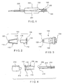
- Figure 1 shows an exemplary embodiment of an introducer sheath stabilizer according to the invention.
- a sheath stabilizer 100 is shown in an operative position within a hub 202 of a microcatheter 200.
- a distal end 102 of the stabilizer 100 is inserted into the hub 202 of the microcatheter 200, such that it abuts the proximal end of a catheter lumen 204.
- an introducer sheath 216 containing an embolic coil 214 is inserted into the proximal end 104 of the stabilizer 100, and is pushed through the stabilizer 100 until it exits out of the distal end 102 of the stabilizer 100, as clearly shown in Figs. 4 and 5 .
- the introducer sheath 216 is then further pushed until it contacts the proximal end of the lumen 204.
- the stabilizer 100 helps to maintain the introducer sheath 216 in place preventing premature coil detachment and jamming of the coil 214 in the catheter hub 202.
- the stabilizer 100 comprises slits 106 formed longitudinally on the walls thereof.
- the slits 106 facilitate the insertion of the introducer sheath 216 into the stabilizer 100, prior to attachment to the catheter hub 202, and also provide a better connection with the catheter hub 202.
- the stabilizer 100 mechanically and frictionally cooperates with the hub 202 to properly position the introducer sheath 216.
- the sheath introducer the stabilizer 100 may also be used to facilitate pre-irrigation of the embolic coil 214 prior to deployment.
- the stabilizer 100 is used to couple a syringe or other source of irrigating fluid to the introducer sheath 216 containing the embolic coil 214.
- the stabilizer 100 thus serves a dual function, facilitating the pre-irrigation of the coil and the insertion of the coil 214 into the microcatheter 200.
- the physician performing the embolization procedure thus can carry out two tasks using only one device which can be provided, for example, together with the introducer sheath 216 as part of the packaging for the embolic coil 214.
- FIGS 2 and 3 show an exemplary embodiment of the stabilizer 100 according to the invention.
- the stabilizer 100 comprises two portions joined to one another.
- a rigid female luer adapter 112 forms the proximal end 104 of the stabilizer 100 and is designed to provide a means of connecting the stabilizer 100 to another device provided with a luer.
- a flexible conical section 110 defines the distal portion 102 and completes the stabilizer 100.
- the flexible conical section 110 is designed to provide a snug fit with the proximal end of the microcatheter, such as by acting as an adapter fitting into the catheter hub 202.
- the stabilizer 100 may also be used to facilitate pre-hydration of the embolic coil 214 while still in the introducer sheath 216.
- the distal end 102 of the flexible conical section 110 becomes a receptacle for the distal tip of the introducer sheath 216.
- a syringe may then be connected to the luer adapter 112 to provide the irrigation.
- the rigid female luer adapter 112 may be formed of any suitable material compatible with conventional luers (for example, polycarbonate, ABS plastic, Tecoplast). As would be understood, the material selected should be sufficiently resilient to maintain the dimensions of the luer adapter 112 during use of the stabilizer 100.
- a lumen 118 extends longitudinally through the luer adapter 112, and joins a lumen 118' which extends through the flexible conical section 110 to form a continuous passage through the stabilizer 100.
- the lumens 118, 118' have dimensions adapted to receive the introducer sheath 216 therethrough.
- the flexible conical section 110 may be formed from polyurethane, santoprene, silicone, natural latex, other thermoplastic elastomers or any material having a suitable flexibility.
- slits or openings 106 may be formed on shell-like walls of the conical section 110, to provide additional flexibility.
- the flexibility of the conical section 110 enables the stabilizer 100 to fit securely in a variety of catheter hubs having different dimensions, to provide a secure and stable interface between the catheter hub and the introducer sheath 216.
- the slitted portion of the flexible conical section 110 allows it to expand and/or contract to fit catheter hubs of different diameters.
- the flexible conical section 110 forms a catheter hub adapter having outer surfaces which substantially match an inner passage of the hub, and which form a frictional and mechanical connection to the hub.
- a radius of the conical section 110 is a minimum at the distal end 102 and a maximum at the proximal end 104, so that conical section 110 can be inserted into the hub until the connection is made.
- the exemplary flexible conical section 110 comprises a distal opening 114 with a sealing device, which may be a valve 120.
- the valve 120 may be of a single slit design, as shown, or may be a dual slit or multi slit design.
- the valve 120 is designed to accept the coil introducer sheath 216 for pre-hydration of the embolic coil 214 contained therein. In this mode, the tip of the introducer sheath 216 is inserted from the outside into the conical section 110 through the valve 120 which forms a seal around the introducer sheath 216.
- the distal tip 206 of the introducer sheath 216 is inserted through a proximal opening 116 of the stabilizer 100 and pushed out of the stabilizer 100 through the valve 120.
- the valve 120 thus permits passage of the introducer sheath 216 in both directions, while providing a sealing action around exterior surfaces of the introducer sheath 216.
- an embolic coil 214 is contained within a tubular passage 218 extending through the sheath 216 from a proximal coil receiving opening to a distal coil deploying opening formed in a distal end 206 thereof.
- the embolic coil 214 is ready for deployment. However, if it is desired to pre-hydrate the coil 214, this may be done without removing the coil 214 from the passage 218.
- the distal tip 206 of the introducer sheath 216 is inserted into the stabilizer 100 via the opening 114 of the distal end 102 so that the distal tip 206 is received within the stabilizer 100 with the distal opening facing the proximal opening 116 in the luer adapter 112.
- the valve 120 provides a seal around the outer surface of the introducer sheath 216, such that a fluid may flow within the lumen 118 to the passage 218 without leaking from the stabilizer 100.
- a syringe 210 or other similar source of hydrating fluid is connected to the luer adapter 112 using a conventional luer attachment, such that the nozzle 212 enters the proximal opening 116 of the stabilizer 100. Fluid such as, for example, a heparinized solution, is then injected into the lumen 118 of the stabilizer 100 from the syringe 210 into the passage 218 of the introducer sheath 216, to reach the coil 214.
- the stabilizer 100 may be used to assist in introducing the coil 214 into a microcatheter 200 via the coil deploying opening in the distal end 206.
- the syringe 210 is disconnected from the stabilizer 100 and the sheath 216 is removed from the stabilizer 100 and reinserted into the stabilizer 100 via the opening 116 at the proximal end thereof.
- the sheath 216 is extended through the valve 120 so that the distal tip 206 protrudes from the distal end of the stabilizer 100.
- introducer sheath stabilizer 100 The coil introduction function of introducer sheath stabilizer 100 is described in more detail with reference to Figure 5 .
- the smaller diameter distal end of the cone-shaped stabilizer 100 is inserted into the catheter hub 302 of a catheter 300.
- the flexible conical section 110 is formed of a pliable material to mate with a tapered inner surface 303 of the catheter hub 302 to form a stable, temporary frictional and mechanical connection with the catheter 300.
- the introducer sheath 216 is then inserted into the stabilizer 100 through the proximal opening 116 and is pushed through the passage 118 until its distal end 206 emerges from the distal opening 114 through the valve 120.
- the introducer sheath 216 is further pushed longitudinally until the coil deploying opening of the distal tip 206 seats in the tapered inner surface 303 substantially adjacent to a proximal opening of the catheter lumen 304.
- the coil 214 may be transferred directly from the passage 218 to the lumen 304 without unwanted movement of the tip 206 relative to seating surfaces of the catheter hub 302. This reduces the chances of premature detachment, damage or entrapment of the coil 214 in the microcatheter hub 302.
- the exemplary multi functional introducer sheath stabilizer allows for embolic coil pre-hydration without removal from the sheath as well as greater ease of coil insertion in a delivery catheter, by using a single device.
- the exemplary device may be used for multiple types of coils, including pushable coils and fibered coils for which pre-deployment and re-sheathing risk reversing or altering the fiber's orientation.
- the inclusion of a luer adapter allows for in line attachment of a rotating hemostatic valve (RHV) for continuous or intermittent heparinized saline flush of the microcatheter lumen.
- RV rotating hemostatic valve
- the introducer sheath stabilizer may be incorporated into an RHV.
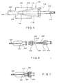
- Figures 6 and 7 show a stabilizer 400 adapted to fit in an RHV placed on the proximal end of a microcatheter 300.
- a distal male luer 406 is adapted to lock to the proximal end of a catheter hub 302 of the microcatheter 300.
- the distal male luer 402 doubles as a valve housing and serves as the bottom valve housing for a valve 402.
- the valve 402 may be a conventional valve used in conjunction with catheters.
- the stabilizer 400 fits through a passage 408 which extends through the valve 402 and through the male valve housing 406 and further extends beyond the RHV to protrude into the microcatheter hub 302.
- the distal end 410 of the stabilizer 400 protrudes sufficiently to engage the tapered portion 301 of the hub 302 and thus seal against any reflux of blood or other fluids from the microcatheter 300.
- a threaded closure may be used to join the male valve housing 406 to a female luer adapter 404, which allows mating to an external device for flushing the microcatheter 300 prior to introducing the coil 214 thereinto.
- the assembly of the male valve housing 406 and the female luer adapter 404 forms a structure which contains the valve 402 and defines a passage 408 containing the stabilizer 400.
- the assembly may be designed so that the valve 402 can be closed by the user, for example by tightening the threads of the assembly.
- Placing the stabilizer 400 within the RHV provides several advantages. Seating the stabilizer 400 in the microcatheter hub 302 helps prevent the occurrence of retrograde blood flow up the sheath 216 reducing the possibility of thrombus build up in the interface between the two parts and reducing friction in the sheath 216. As in the examplary construction described above, the stabilizer 400 maintains the introducer sheath 216 (not shown in Fig.
- the valve 402 prevents kickback of the sheath 216 and together with the stabilizer 400 reduces coil jamming and premature detachment.
- the distal portion of the sheath 216 may be formed of a compressible material adapted to.conform to the inner surfaces of a variety of microcatheter hubs.
- This universal compatibility of the stabilizer 400 with different catheters and hubs may be enhanced by slots 412 formed in the conical portion of the stabilizer 400.
- the slots 412 help the proximal portion of the stabilizer 400 to widen or narrow to fit different size passages, so that the stabilizer 400 provides a properly sized passage to an introducer sheath 216 containing a coil 214 regardless of the size of the catheter or hub.
Landscapes
- Health & Medical Sciences (AREA)
- Life Sciences & Earth Sciences (AREA)
- Surgery (AREA)
- Engineering & Computer Science (AREA)
- Biomedical Technology (AREA)
- Animal Behavior & Ethology (AREA)
- Veterinary Medicine (AREA)
- Vascular Medicine (AREA)
- Public Health (AREA)
- Heart & Thoracic Surgery (AREA)
- General Health & Medical Sciences (AREA)
- Molecular Biology (AREA)
- Medical Informatics (AREA)
- Nuclear Medicine, Radiotherapy & Molecular Imaging (AREA)
- Reproductive Health (AREA)
- Cardiology (AREA)
- Oral & Maxillofacial Surgery (AREA)
- Transplantation (AREA)
- Neurosurgery (AREA)
- Surgical Instruments (AREA)
- Media Introduction/Drainage Providing Device (AREA)
Claims (16)
- Vorrichtung zum Einführen einer embolischen Spirale (214) in einen Katheter (200), die aufweist:einen Schleusenstabilisator (100), der einen länglichen Körper (110) aufweist, der einen longitudinalen Durchgang (118) definiert, der sich dort hindurch von einer ersten Öffnung (116) an einem proximalen Ende (104) davon zu einer zweiten Öffnung (114) an einem distalen Ende (102) davon erstreckt, wobei der längliche Körper (110) einen Passabschnitt zur Anpassung an eine Größe und Form einer Öffnung in einem Ansatzstück (202) eines Katheters (200) aufweist, der damit verbunden werden soll, wobei der längliche Körper ein Ventil (120) aufweist, das die zweite Öffnung (114) abdichtet; undeine Einführschleuse (216) für eine embolische Spirale, die ein Spiralaufnahmelumen (218) aufweist, das sich dort hindurch erstreckt und eine embolische Spirale (214) enthält, wobei eine distale Spitze (206) der Einführschleuse (216) dimensioniert ist, in ein proximales Ende des longitudinalen Durchgangs (118) aufgenommen zu werden, wobei das Ventil (120) eingerichtet ist, die Einführschleuse (216) aufzunehmen und um sie herum abzudichten, wobei es um die Einführschleuse (216) abdichtet, wenn sie von außerhalb des länglichen Körpers (110) in eine Richtung distal nach proximal in den länglichen Körper (110) eingesetzt wird;wobei die zweite Öffnung (114) am distalen Ende (102) des länglichen Körpers (110) außerdem so konfiguriert ist, dass die distale Spitze (206) der Einführschleuse (216) für eine embolische Spirale in den länglichen Körper (110) des Schleusenstabilisators (100) so eingesetzt werden kann, dass ein Fluid innerhalb des longitudinalen Durchgangs (118) fließen kann, ohne aus dem Schleusenstabilisator (100) auszulaufen, um die embolische Spirale (214) im Voraus zu hydratisieren.
- Vorrichtung nach Anspruch 1, wobei das Ventil (120) eine Schlitzmembran aufweist.
- Vorrichtung nach Anspruch 1, wobei sich der Passabschnitt von einem distalen Ende des länglichen Körpers zu einem proximalen Ende davon erstreckt und einen flexiblen, im Wesentlichen konischen Abschnitt (110) zur mechanischen und reibenden Passung mit einer Aussparung im Katheteransatzstück (202) aufweist.
- Vorrichtung nach Anspruch 3, wobei der flexible konische Abschnitt (110) aus Polyurethan oder Santopren oder Silikon oder Naturlatex oder thermoplastischen Elastomeren ausgebildet ist.
- Vorrichtung nach Anspruch 3, wobei der flexible konische Abschnitt (110) eine Außenfläche aufweist, die im Wesentlichen zu einer Innenfläche der Aussparung des Katheteransatzstücks (202) passt.
- Vorrichtung nach Anspruch 3, wobei der Passabschnitt ferner eine Vielzahl von darin ausgebildeten Schlitzen (106) aufweist, die ihm eine zusätzliche Flexibilität verleihen.
- Vorrichtung nach Anspruch 1, die ferner einen am proximalen Ende des länglichen Körpers ausgebildeten Luer-Ansatzadapter (112) aufweist.
- Vorrichtung nach Anspruch 7, wobei der Luer-Ansatzadapter (112) aus Polykarbonat oder ABS oder Tecoplast ausgebildet ist.
- System zum Einführen einer Spirale (214) in einen Katheter (200) zum Einsatz in einem Körperlumen, wobei das System aufweist:einen Stabilisator (100), der einen steifen Luer-Adapter (112) an einem proximalen Ende davon und einen flexiblen Katheteransatzstück-Passabschnitt (110) aufweist, der sich vom Luer-Adapter (112) zu einem distalen Ende des Stabilisators (100) erstreckt, wobei sich ein Durchgang (118) vom proximalen Ende durch den Stabilisator (100) zu einer Öffnung (114) erstreckt, die im distalen Ende ausgebildet ist, wobei der Stabilisator (100) ein Ventil (120) aufweist, das die Öffnung (114) des distalen Endes abdichtet; und eine Einführschleuse (216), die ein Spiralaufnahmelumen (218) aufweist, das sich dort hindurch zu einer Spiraleinsatzöffnung erstreckt und eine embolische Spirale enthält, wobei ein distaler Abschnitt (206) der Schleuse (216) zum Einsetzen durch den Durchgang (118) bemessen ist, um distal aus der distalen Öffnung (114) vorzustehen, wobei der distale Abschnitt (206) der Schleuse (216) und der Passabschnitt (110) so bemessen sind, dass wenn der Passabschnitt (110) zu einer wirksamen Position innerhalb eines Ansatzstücks (202) eines Katheters (200) eingesetzt wird, wobei der distale Abschnitt (206) der Schleuse (216) davon vorsteht, die Spiraleneinsatzöffnung an eine proximale Öffnung des Katheters (200) anliegt, wobei das Ventil (120) eingerichtet ist, die Einführschleuse (216) aufzunehmen und um sie herum abzudichten, wobei es um die Einführschleuse (216) abdichtet, wenn sie von außerhalb des Stabilisators (100) in eine Richtung distal nach proximal in den Stabilisator (100) eingesetzt wird;wobei die distale Öffnung (114) im distalen Ende des Stabilisator (100) außerdem so konfiguriert ist, dass der distale Abschnitt (206) der Einführschleuse (216) in den Passabschnitt (110) des Stabilisators (100) so eingesetzt werden kann, dass ein Fluid innerhalb des Durchgangs (118) fließen kann, ohne aus dem Stabilisator (100) auszulaufen, um die Spirale (214) im Voraus zu hydratisieren.
- System nach Anspruch 9, wobei das Ventil (120) eine Membran mit mindestens einem darin ausgebildeten Schlitz aufweist.
- System nach Anspruch 9, wobei eine Außenfläche des Passabschnitts im Wesentlichen ähnlich zu einer Innenfläche des Katheteransatzstücks (202) geformt ist.
- System nach Anspruch 11, wobei die Außenfläche des Passabschnitt im Wesentlichen konisch ist.
- System nach Anspruch 12, wobei der Passabschnitt eine Vielzahl von Schlitzen (106) aufweist, die ihm eine erhöhte Flexibilität verleihen.
- System nach Anspruch 12, wobei sich ein Abschnitt mit minimalem Radius des Passabschnitts benachbart zum distalen Ende des Stabilisators (100) befindet und sich ein Abschnitt mit maximalem Radius davon benachbart zum Luer-Adapter (112) befindet.
- System nach Anspruch 9, wobei der Passabschnitt, wenn er in ein Ansatzstück (202) eines Katheters (200) eingeführt wird, das Ansatzstück (202) reibend und mechanisch in Eingriff nimmt, um eine erwünschte relative Position der Schleuse (216) und des Katheters (200) während einer Einführung einer Spirale (214) darin aufrechtzuerhalten.
- System nach Anspruch 9, wobei der steife Luer-Adapter (112) und der Passabschnitt reibungsverbunden sind.
Applications Claiming Priority (2)
| Application Number | Priority Date | Filing Date | Title |
|---|---|---|---|
| US10/833,982 US7367980B2 (en) | 2004-04-28 | 2004-04-28 | Introducer sheath stabilizer |
| PCT/US2005/002337 WO2005107612A1 (en) | 2004-04-28 | 2005-01-25 | Introducer sheath stabilizer |
Publications (2)
| Publication Number | Publication Date |
|---|---|
| EP1746942A1 EP1746942A1 (de) | 2007-01-31 |
| EP1746942B1 true EP1746942B1 (de) | 2016-06-29 |
Family
ID=34960450
Family Applications (1)
| Application Number | Title | Priority Date | Filing Date |
|---|---|---|---|
| EP05712001.6A Expired - Lifetime EP1746942B1 (de) | 2004-04-28 | 2005-01-25 | Stabilisator für eine einführhülse |
Country Status (5)
| Country | Link |
|---|---|
| US (2) | US7367980B2 (de) |
| EP (1) | EP1746942B1 (de) |
| JP (1) | JP4709829B2 (de) |
| CA (1) | CA2564794C (de) |
| WO (1) | WO2005107612A1 (de) |
Families Citing this family (29)
| Publication number | Priority date | Publication date | Assignee | Title |
|---|---|---|---|---|
| US20110144661A1 (en) * | 2001-04-24 | 2011-06-16 | Houser Russell A | Tissue closure devices, device and systems for delivery, kits and methods therefor |
| US8961541B2 (en) | 2007-12-03 | 2015-02-24 | Cardio Vascular Technologies Inc. | Vascular closure devices, systems, and methods of use |
| US8992567B1 (en) | 2001-04-24 | 2015-03-31 | Cardiovascular Technologies Inc. | Compressible, deformable, or deflectable tissue closure devices and method of manufacture |
| US20070239271A1 (en) * | 2006-04-10 | 2007-10-11 | Than Nguyen | Systems and methods for loading a prosthesis onto a minimally invasive delivery system |
| US8398696B2 (en) * | 2007-03-01 | 2013-03-19 | Boston Scientific Scimed, Inc. | Microcatheter introducer sheath |
| ATE469608T1 (de) | 2007-03-05 | 2010-06-15 | Boston Scient Scimed Inc | Ablage von embolie-spulen |
| JP5134729B2 (ja) | 2008-07-01 | 2013-01-30 | エンドロジックス、インク | カテーテルシステム |
| US8790364B2 (en) * | 2008-12-10 | 2014-07-29 | Boston Scientific Scimed, Inc. | Introducer sheath for use with an embolic coil device and methods for making and using the same |
| US8043325B2 (en) * | 2008-12-17 | 2011-10-25 | Cook Medical Technologies Llc | Loading device for delivering an embolization coil into a microcatheter |
| EP2416711A4 (de) | 2009-04-09 | 2017-06-07 | Cardiovascular Technologies, Inc. | Gewebeverschlussvorrichtungen, freisetzungsvorrichtung und -systeme, kits und verfahren dafür |
| WO2012118901A1 (en) | 2011-03-01 | 2012-09-07 | Endologix, Inc. | Catheter system and methods of using same |
| KR101132841B1 (ko) | 2011-03-07 | 2012-04-02 | 김영재 | 봉합사 |
| KR101185583B1 (ko) | 2011-12-27 | 2012-09-24 | 김영재 | 매듭짓는 작업이 필요 없는 봉합사 및 이를 포함하는 키트 |
| US10188396B2 (en) | 2012-08-06 | 2019-01-29 | Covidien Lp | Apparatus and method for delivering an embolic composition |
| US9427219B2 (en) | 2012-11-19 | 2016-08-30 | Cook Medical Technologies Llc | Delivery device for vascular occluding device |
| US10178990B2 (en) * | 2012-12-05 | 2019-01-15 | Y. Jacobs Medical Inc. | Apparatus for inserting surgical thread, and surgical procedure kit for inserting surgical thread comprising same |
| US10010317B2 (en) | 2012-12-05 | 2018-07-03 | Young Jae Kim | Method of improving elasticity of tissue of living body |
| CA2927541C (en) * | 2013-10-15 | 2021-06-08 | Radux Devices, LLC | Securing a medical device to a valve instrument |
| WO2015083864A1 (ko) | 2013-12-06 | 2015-06-11 | 주식회사 와이제이콥스메디칼 | 의료용 관 삽입 장치 및 이를 구비한 의료용 관 삽입 시술 키트 |
| US11318287B2 (en) * | 2015-06-10 | 2022-05-03 | B. Braun Melsungen Ag | Catheter hub with flexible extended fluid connector and related methods |
| WO2017004265A1 (en) | 2015-06-30 | 2017-01-05 | Endologix, Inc. | Locking assembly for coupling guidewire to delivery system |
| US10953196B2 (en) * | 2016-09-14 | 2021-03-23 | Boston Scientific Scimed, Inc. | Catheter hubs |
| CN108742962A (zh) * | 2018-06-12 | 2018-11-06 | 北京久事神康医疗科技有限公司 | 一种支架输送系统 |
| CN108784801A (zh) * | 2018-07-17 | 2018-11-13 | 中山大学附属第医院 | 一种肝胆道穿刺套件 |
| CN111375118B (zh) * | 2018-12-29 | 2025-07-18 | 微创神通医疗科技(上海)有限公司 | 导引装置及导引系统 |
| EP3979930B1 (de) * | 2019-06-12 | 2024-08-21 | Bard Access Systems, Inc. | Mikroeinführungssystem |
| WO2022237605A1 (zh) * | 2021-05-10 | 2022-11-17 | 杭州德诺脑神经医疗科技有限公司 | 递送系统 |
| CN113317917B (zh) * | 2021-06-25 | 2023-03-24 | 上海心玮医疗科技股份有限公司 | 一种颅内血管支架导入微导管的装置及成型方法 |
| WO2025243356A1 (ja) * | 2024-05-20 | 2025-11-27 | 大塚メディカルデバイス株式会社 | イントロデューサーシース、ハブ及びシステム |
Family Cites Families (9)
| Publication number | Priority date | Publication date | Assignee | Title |
|---|---|---|---|---|
| JPH03130047A (ja) * | 1989-10-16 | 1991-06-03 | Ninben:Kk | だし液の抽出方法 |
| CA2068584C (en) * | 1991-06-18 | 1997-04-22 | Paul H. Burmeister | Intravascular guide wire and method for manufacture thereof |
| US6090072A (en) * | 1992-10-15 | 2000-07-18 | Scimed Life Systems, Inc. | Expandable introducer sheath |
| US5382260A (en) * | 1992-10-30 | 1995-01-17 | Interventional Therapeutics Corp. | Embolization device and apparatus including an introducer cartridge and method for delivering the same |
| US20020198586A1 (en) | 1995-04-12 | 2002-12-26 | Kanji Inoue | Appliance collapsible for insertion into a human organ and capable of resilient restoration |
| US5746764A (en) * | 1995-12-04 | 1998-05-05 | Atrion Medical Products, Inc. | Stent compression instrument |
| US20010045575A1 (en) | 1998-05-01 | 2001-11-29 | Mark Ashby | Device and method for facilitating hemostasis of a biopsy tract |
| ATE245389T1 (de) | 2001-05-03 | 2003-08-15 | Radi Medical Systems | Führungswerkzeug für wundverschluss |
| AU2003270777A1 (en) | 2002-09-23 | 2004-04-08 | Nmt Medical, Inc. | Loader for prosthetic occluders and methods thereof |
-
2004
- 2004-04-28 US US10/833,982 patent/US7367980B2/en not_active Expired - Lifetime
-
2005
- 2005-01-25 WO PCT/US2005/002337 patent/WO2005107612A1/en not_active Ceased
- 2005-01-25 EP EP05712001.6A patent/EP1746942B1/de not_active Expired - Lifetime
- 2005-01-25 JP JP2007510708A patent/JP4709829B2/ja not_active Expired - Lifetime
- 2005-01-25 CA CA2564794A patent/CA2564794C/en not_active Expired - Fee Related
-
2008
- 2008-04-02 US US12/061,407 patent/US8123759B2/en active Active
Also Published As
| Publication number | Publication date |
|---|---|
| JP2007534439A (ja) | 2007-11-29 |
| WO2005107612A1 (en) | 2005-11-17 |
| CA2564794A1 (en) | 2005-11-17 |
| US20080183183A1 (en) | 2008-07-31 |
| US7367980B2 (en) | 2008-05-06 |
| CA2564794C (en) | 2014-06-17 |
| JP4709829B2 (ja) | 2011-06-29 |
| US8123759B2 (en) | 2012-02-28 |
| EP1746942A1 (de) | 2007-01-31 |
| US20050245963A1 (en) | 2005-11-03 |
Similar Documents
| Publication | Publication Date | Title |
|---|---|---|
| US8123759B2 (en) | Introducer sheath stabilizer | |
| JP5132702B2 (ja) | 血管の創傷をふさぐ装置および方法 | |
| US10328239B2 (en) | Intravenous catheter and insertion device with reduced blood spatter | |
| EP1507569B1 (de) | Verabreichungsvorrichtung einer flüssigen emboliezusammensetzung | |
| US20210290213A1 (en) | Vessel access and closure assist system and method | |
| US6890342B2 (en) | Method and apparatus for closing vascular puncture using hemostatic material | |
| EP1709986A1 (de) | Integrierte abnehmbare Einführhilfe | |
| WO2003061457A2 (en) | Methods and devices for percutaneous and surgical interventions | |
| US20230145301A1 (en) | Medical instrument set, delivery system, and embolic device delivery medical system | |
| US20150335415A1 (en) | Intravenous filter with guidewire and catheter access guide | |
| PL237853B1 (pl) | Zestaw cewnika do dializy | |
| CN116710170A (zh) | 促进临时直接进入血管的血管管道 | |
| JP7633858B2 (ja) | 注入具 | |
| US20250360297A1 (en) | Vascular access reversing device and method for treating endovascular infarction | |
| WO2023042909A1 (ja) | カテーテルおよび塞栓物装填済みカテーテル | |
| WO2026036116A9 (en) | Vascular access reversing device and method for treating endovascular infarction | |
| WO2024196914A2 (en) | Introducer sheath with occlusion capability | |
| WO2023048083A1 (ja) | 塞栓物装填済みカテーテルおよび医療器具セット | |
| WO2023054320A1 (ja) | 医療器具およびデリバリーシステム | |
| JP2016185277A (ja) | イントロデューサーシースおよびイントロデューサー組立体 |
Legal Events
| Date | Code | Title | Description |
|---|---|---|---|
| PUAI | Public reference made under article 153(3) epc to a published international application that has entered the european phase |
Free format text: ORIGINAL CODE: 0009012 |
|
| 17P | Request for examination filed |
Effective date: 20061017 |
|
| AK | Designated contracting states |
Kind code of ref document: A1 Designated state(s): AT BE BG CH CY CZ DE DK EE ES FI FR GB GR HU IE IS IT LI LT LU MC NL PL PT RO SE SI SK TR |
|
| RIN1 | Information on inventor provided before grant (corrected) |
Inventor name: BUISER, MARCIA Inventor name: KIDA, TOSHIAKI Inventor name: SEEHUSEN, ASHLEY Inventor name: ELLIOTT, CHRISTOPHER J. |
|
| DAX | Request for extension of the european patent (deleted) | ||
| 17Q | First examination report despatched |
Effective date: 20081015 |
|
| RAP1 | Party data changed (applicant data changed or rights of an application transferred) |
Owner name: BOSTON SCIENTIFIC LIMITED |
|
| GRAP | Despatch of communication of intention to grant a patent |
Free format text: ORIGINAL CODE: EPIDOSNIGR1 |
|
| INTG | Intention to grant announced |
Effective date: 20151216 |
|
| RIN1 | Information on inventor provided before grant (corrected) |
Inventor name: BUISER, MARCIA Inventor name: KIDA, TOSHIAKI Inventor name: ELLIOTT, CHRISTOPHER J. Inventor name: SEEHUSEN, ASHLEY |
|
| GRAS | Grant fee paid |
Free format text: ORIGINAL CODE: EPIDOSNIGR3 |
|
| GRAA | (expected) grant |
Free format text: ORIGINAL CODE: 0009210 |
|
| AK | Designated contracting states |
Kind code of ref document: B1 Designated state(s): AT BE BG CH CY CZ DE DK EE ES FI FR GB GR HU IE IS IT LI LT LU MC NL PL PT RO SE SI SK TR |
|
| REG | Reference to a national code |
Ref country code: GB Ref legal event code: FG4D |
|
| REG | Reference to a national code |
Ref country code: DE Ref legal event code: R081 Ref document number: 602005049621 Country of ref document: DE Owner name: BOSTON SCIENTIFIC MEDICAL DEVICE LIMITED, IE Free format text: FORMER OWNER: BOSTON SCIENTIFIC LTD., BARBADOS, WEST INDIES, BB Ref country code: CH Ref legal event code: EP |
|
| REG | Reference to a national code |
Ref country code: AT Ref legal event code: REF Ref document number: 808447 Country of ref document: AT Kind code of ref document: T Effective date: 20160715 |
|
| REG | Reference to a national code |
Ref country code: IE Ref legal event code: FG4D |
|
| REG | Reference to a national code |
Ref country code: DE Ref legal event code: R096 Ref document number: 602005049621 Country of ref document: DE |
|
| REG | Reference to a national code |
Ref country code: NL Ref legal event code: FP |
|
| REG | Reference to a national code |
Ref country code: LT Ref legal event code: MG4D |
|
| PG25 | Lapsed in a contracting state [announced via postgrant information from national office to epo] |
Ref country code: LT Free format text: LAPSE BECAUSE OF FAILURE TO SUBMIT A TRANSLATION OF THE DESCRIPTION OR TO PAY THE FEE WITHIN THE PRESCRIBED TIME-LIMIT Effective date: 20160629 Ref country code: FI Free format text: LAPSE BECAUSE OF FAILURE TO SUBMIT A TRANSLATION OF THE DESCRIPTION OR TO PAY THE FEE WITHIN THE PRESCRIBED TIME-LIMIT Effective date: 20160629 |
|
| PG25 | Lapsed in a contracting state [announced via postgrant information from national office to epo] |
Ref country code: SE Free format text: LAPSE BECAUSE OF FAILURE TO SUBMIT A TRANSLATION OF THE DESCRIPTION OR TO PAY THE FEE WITHIN THE PRESCRIBED TIME-LIMIT Effective date: 20160629 Ref country code: GR Free format text: LAPSE BECAUSE OF FAILURE TO SUBMIT A TRANSLATION OF THE DESCRIPTION OR TO PAY THE FEE WITHIN THE PRESCRIBED TIME-LIMIT Effective date: 20160930 |
|
| REG | Reference to a national code |
Ref country code: AT Ref legal event code: MK05 Ref document number: 808447 Country of ref document: AT Kind code of ref document: T Effective date: 20160629 |
|
| PG25 | Lapsed in a contracting state [announced via postgrant information from national office to epo] |
Ref country code: RO Free format text: LAPSE BECAUSE OF FAILURE TO SUBMIT A TRANSLATION OF THE DESCRIPTION OR TO PAY THE FEE WITHIN THE PRESCRIBED TIME-LIMIT Effective date: 20160629 Ref country code: SK Free format text: LAPSE BECAUSE OF FAILURE TO SUBMIT A TRANSLATION OF THE DESCRIPTION OR TO PAY THE FEE WITHIN THE PRESCRIBED TIME-LIMIT Effective date: 20160629 Ref country code: CZ Free format text: LAPSE BECAUSE OF FAILURE TO SUBMIT A TRANSLATION OF THE DESCRIPTION OR TO PAY THE FEE WITHIN THE PRESCRIBED TIME-LIMIT Effective date: 20160629 Ref country code: EE Free format text: LAPSE BECAUSE OF FAILURE TO SUBMIT A TRANSLATION OF THE DESCRIPTION OR TO PAY THE FEE WITHIN THE PRESCRIBED TIME-LIMIT Effective date: 20160629 Ref country code: IS Free format text: LAPSE BECAUSE OF FAILURE TO SUBMIT A TRANSLATION OF THE DESCRIPTION OR TO PAY THE FEE WITHIN THE PRESCRIBED TIME-LIMIT Effective date: 20161029 Ref country code: IT Free format text: LAPSE BECAUSE OF FAILURE TO SUBMIT A TRANSLATION OF THE DESCRIPTION OR TO PAY THE FEE WITHIN THE PRESCRIBED TIME-LIMIT Effective date: 20160629 |
|
| PG25 | Lapsed in a contracting state [announced via postgrant information from national office to epo] |
Ref country code: PL Free format text: LAPSE BECAUSE OF FAILURE TO SUBMIT A TRANSLATION OF THE DESCRIPTION OR TO PAY THE FEE WITHIN THE PRESCRIBED TIME-LIMIT Effective date: 20160629 Ref country code: AT Free format text: LAPSE BECAUSE OF FAILURE TO SUBMIT A TRANSLATION OF THE DESCRIPTION OR TO PAY THE FEE WITHIN THE PRESCRIBED TIME-LIMIT Effective date: 20160629 Ref country code: ES Free format text: LAPSE BECAUSE OF FAILURE TO SUBMIT A TRANSLATION OF THE DESCRIPTION OR TO PAY THE FEE WITHIN THE PRESCRIBED TIME-LIMIT Effective date: 20160629 Ref country code: BE Free format text: LAPSE BECAUSE OF FAILURE TO SUBMIT A TRANSLATION OF THE DESCRIPTION OR TO PAY THE FEE WITHIN THE PRESCRIBED TIME-LIMIT Effective date: 20160629 Ref country code: PT Free format text: LAPSE BECAUSE OF FAILURE TO SUBMIT A TRANSLATION OF THE DESCRIPTION OR TO PAY THE FEE WITHIN THE PRESCRIBED TIME-LIMIT Effective date: 20161031 |
|
| REG | Reference to a national code |
Ref country code: DE Ref legal event code: R097 Ref document number: 602005049621 Country of ref document: DE |
|
| PLBE | No opposition filed within time limit |
Free format text: ORIGINAL CODE: 0009261 |
|
| STAA | Information on the status of an ep patent application or granted ep patent |
Free format text: STATUS: NO OPPOSITION FILED WITHIN TIME LIMIT |
|
| PG25 | Lapsed in a contracting state [announced via postgrant information from national office to epo] |
Ref country code: DK Free format text: LAPSE BECAUSE OF FAILURE TO SUBMIT A TRANSLATION OF THE DESCRIPTION OR TO PAY THE FEE WITHIN THE PRESCRIBED TIME-LIMIT Effective date: 20160629 |
|
| 26N | No opposition filed |
Effective date: 20170330 |
|
| PG25 | Lapsed in a contracting state [announced via postgrant information from national office to epo] |
Ref country code: BG Free format text: LAPSE BECAUSE OF FAILURE TO SUBMIT A TRANSLATION OF THE DESCRIPTION OR TO PAY THE FEE WITHIN THE PRESCRIBED TIME-LIMIT Effective date: 20160929 Ref country code: SI Free format text: LAPSE BECAUSE OF FAILURE TO SUBMIT A TRANSLATION OF THE DESCRIPTION OR TO PAY THE FEE WITHIN THE PRESCRIBED TIME-LIMIT Effective date: 20160629 |
|
| REG | Reference to a national code |
Ref country code: CH Ref legal event code: PL |
|
| GBPC | Gb: european patent ceased through non-payment of renewal fee |
Effective date: 20170125 |
|
| PG25 | Lapsed in a contracting state [announced via postgrant information from national office to epo] |
Ref country code: MC Free format text: LAPSE BECAUSE OF FAILURE TO SUBMIT A TRANSLATION OF THE DESCRIPTION OR TO PAY THE FEE WITHIN THE PRESCRIBED TIME-LIMIT Effective date: 20160629 |
|
| REG | Reference to a national code |
Ref country code: FR Ref legal event code: ST Effective date: 20170929 |
|
| PG25 | Lapsed in a contracting state [announced via postgrant information from national office to epo] |
Ref country code: CH Free format text: LAPSE BECAUSE OF NON-PAYMENT OF DUE FEES Effective date: 20170131 Ref country code: FR Free format text: LAPSE BECAUSE OF NON-PAYMENT OF DUE FEES Effective date: 20170131 Ref country code: LI Free format text: LAPSE BECAUSE OF NON-PAYMENT OF DUE FEES Effective date: 20170131 |
|
| PG25 | Lapsed in a contracting state [announced via postgrant information from national office to epo] |
Ref country code: LU Free format text: LAPSE BECAUSE OF NON-PAYMENT OF DUE FEES Effective date: 20170125 Ref country code: GB Free format text: LAPSE BECAUSE OF NON-PAYMENT OF DUE FEES Effective date: 20170125 |
|
| PG25 | Lapsed in a contracting state [announced via postgrant information from national office to epo] |
Ref country code: HU Free format text: LAPSE BECAUSE OF FAILURE TO SUBMIT A TRANSLATION OF THE DESCRIPTION OR TO PAY THE FEE WITHIN THE PRESCRIBED TIME-LIMIT; INVALID AB INITIO Effective date: 20050125 |
|
| PG25 | Lapsed in a contracting state [announced via postgrant information from national office to epo] |
Ref country code: CY Free format text: LAPSE BECAUSE OF NON-PAYMENT OF DUE FEES Effective date: 20160629 |
|
| PG25 | Lapsed in a contracting state [announced via postgrant information from national office to epo] |
Ref country code: TR Free format text: LAPSE BECAUSE OF FAILURE TO SUBMIT A TRANSLATION OF THE DESCRIPTION OR TO PAY THE FEE WITHIN THE PRESCRIBED TIME-LIMIT Effective date: 20160629 |
|
| REG | Reference to a national code |
Ref country code: DE Ref legal event code: R081 Ref document number: 602005049621 Country of ref document: DE Owner name: BOSTON SCIENTIFIC MEDICAL DEVICE LIMITED, IE Free format text: FORMER OWNER: BOSTON SCIENTIFIC LIMITED, HAMILTON, BM |
|
| P01 | Opt-out of the competence of the unified patent court (upc) registered |
Effective date: 20230523 |
|
| REG | Reference to a national code |
Ref country code: NL Ref legal event code: PD Owner name: BOSTON SCIENTIFIC MEDICAL DEVICE LIMITED; IE Free format text: DETAILS ASSIGNMENT: CHANGE OF OWNER(S), ASSIGNMENT; FORMER OWNER NAME: BOSTON SCIENTIFIC LIMITED Effective date: 20230929 |
|
| PGFP | Annual fee paid to national office [announced via postgrant information from national office to epo] |
Ref country code: NL Payment date: 20231219 Year of fee payment: 20 Ref country code: IE Payment date: 20231221 Year of fee payment: 20 |
|
| PGFP | Annual fee paid to national office [announced via postgrant information from national office to epo] |
Ref country code: DE Payment date: 20231219 Year of fee payment: 20 |
|
| REG | Reference to a national code |
Ref country code: NL Ref legal event code: MK Effective date: 20250124 |
|
| REG | Reference to a national code |
Ref country code: DE Ref legal event code: R071 Ref document number: 602005049621 Country of ref document: DE |
|
| REG | Reference to a national code |
Ref country code: IE Ref legal event code: MK9A |
|
| PG25 | Lapsed in a contracting state [announced via postgrant information from national office to epo] |
Ref country code: IE Free format text: LAPSE BECAUSE OF EXPIRATION OF PROTECTION Effective date: 20250125 |