EP3979930B1 - Mikroeinführungssystem - Google Patents
Mikroeinführungssystem Download PDFInfo
- Publication number
- EP3979930B1 EP3979930B1 EP20821927.9A EP20821927A EP3979930B1 EP 3979930 B1 EP3979930 B1 EP 3979930B1 EP 20821927 A EP20821927 A EP 20821927A EP 3979930 B1 EP3979930 B1 EP 3979930B1
- Authority
- EP
- European Patent Office
- Prior art keywords
- microintroducer
- adapter
- stylet
- angled portion
- shape sensing
- Prior art date
- Legal status (The legal status is an assumption and is not a legal conclusion. Google has not performed a legal analysis and makes no representation as to the accuracy of the status listed.)
- Active
Links
Images
Classifications
-
- A—HUMAN NECESSITIES
- A61—MEDICAL OR VETERINARY SCIENCE; HYGIENE
- A61B—DIAGNOSIS; SURGERY; IDENTIFICATION
- A61B17/00—Surgical instruments, devices or methods
- A61B17/34—Trocars; Puncturing needles
- A61B17/3415—Trocars; Puncturing needles for introducing tubes or catheters, e.g. gastrostomy tubes, drain catheters
-
- A—HUMAN NECESSITIES
- A61—MEDICAL OR VETERINARY SCIENCE; HYGIENE
- A61B—DIAGNOSIS; SURGERY; IDENTIFICATION
- A61B5/00—Measuring for diagnostic purposes; Identification of persons
- A61B5/68—Arrangements of detecting, measuring or recording means, e.g. sensors, in relation to patient
- A61B5/6846—Arrangements of detecting, measuring or recording means, e.g. sensors, in relation to patient specially adapted to be brought in contact with an internal body part, i.e. invasive
- A61B5/6847—Arrangements of detecting, measuring or recording means, e.g. sensors, in relation to patient specially adapted to be brought in contact with an internal body part, i.e. invasive mounted on an invasive device
- A61B5/6852—Catheters
-
- A—HUMAN NECESSITIES
- A61—MEDICAL OR VETERINARY SCIENCE; HYGIENE
- A61B—DIAGNOSIS; SURGERY; IDENTIFICATION
- A61B17/00—Surgical instruments, devices or methods
- A61B17/34—Trocars; Puncturing needles
- A61B17/3403—Needle locating or guiding means
-
- A—HUMAN NECESSITIES
- A61—MEDICAL OR VETERINARY SCIENCE; HYGIENE
- A61B—DIAGNOSIS; SURGERY; IDENTIFICATION
- A61B17/00—Surgical instruments, devices or methods
- A61B17/34—Trocars; Puncturing needles
- A61B17/3468—Trocars; Puncturing needles for implanting or removing devices, e.g. prostheses, implants, seeds, wires
-
- A—HUMAN NECESSITIES
- A61—MEDICAL OR VETERINARY SCIENCE; HYGIENE
- A61B—DIAGNOSIS; SURGERY; IDENTIFICATION
- A61B5/00—Measuring for diagnostic purposes; Identification of persons
- A61B5/06—Devices, other than using radiation, for detecting or locating foreign bodies ; Determining position of diagnostic devices within or on the body of the patient
- A61B5/065—Determining position of the probe employing exclusively positioning means located on or in the probe, e.g. using position sensors arranged on the probe
-
- A—HUMAN NECESSITIES
- A61—MEDICAL OR VETERINARY SCIENCE; HYGIENE
- A61B—DIAGNOSIS; SURGERY; IDENTIFICATION
- A61B5/00—Measuring for diagnostic purposes; Identification of persons
- A61B5/68—Arrangements of detecting, measuring or recording means, e.g. sensors, in relation to patient
- A61B5/6846—Arrangements of detecting, measuring or recording means, e.g. sensors, in relation to patient specially adapted to be brought in contact with an internal body part, i.e. invasive
- A61B5/6847—Arrangements of detecting, measuring or recording means, e.g. sensors, in relation to patient specially adapted to be brought in contact with an internal body part, i.e. invasive mounted on an invasive device
- A61B5/6848—Needles
-
- A—HUMAN NECESSITIES
- A61—MEDICAL OR VETERINARY SCIENCE; HYGIENE
- A61B—DIAGNOSIS; SURGERY; IDENTIFICATION
- A61B5/00—Measuring for diagnostic purposes; Identification of persons
- A61B5/68—Arrangements of detecting, measuring or recording means, e.g. sensors, in relation to patient
- A61B5/6846—Arrangements of detecting, measuring or recording means, e.g. sensors, in relation to patient specially adapted to be brought in contact with an internal body part, i.e. invasive
- A61B5/6847—Arrangements of detecting, measuring or recording means, e.g. sensors, in relation to patient specially adapted to be brought in contact with an internal body part, i.e. invasive mounted on an invasive device
- A61B5/6851—Guide wires
-
- A—HUMAN NECESSITIES
- A61—MEDICAL OR VETERINARY SCIENCE; HYGIENE
- A61J—CONTAINERS SPECIALLY ADAPTED FOR MEDICAL OR PHARMACEUTICAL PURPOSES; DEVICES OR METHODS SPECIALLY ADAPTED FOR BRINGING PHARMACEUTICAL PRODUCTS INTO PARTICULAR PHYSICAL OR ADMINISTERING FORMS; DEVICES FOR ADMINISTERING FOOD OR MEDICINES ORALLY; BABY COMFORTERS; DEVICES FOR RECEIVING SPITTLE
- A61J15/00—Feeding-tubes for therapeutic purposes
- A61J15/0015—Gastrostomy feeding-tubes
-
- A—HUMAN NECESSITIES
- A61—MEDICAL OR VETERINARY SCIENCE; HYGIENE
- A61J—CONTAINERS SPECIALLY ADAPTED FOR MEDICAL OR PHARMACEUTICAL PURPOSES; DEVICES OR METHODS SPECIALLY ADAPTED FOR BRINGING PHARMACEUTICAL PRODUCTS INTO PARTICULAR PHYSICAL OR ADMINISTERING FORMS; DEVICES FOR ADMINISTERING FOOD OR MEDICINES ORALLY; BABY COMFORTERS; DEVICES FOR RECEIVING SPITTLE
- A61J15/00—Feeding-tubes for therapeutic purposes
- A61J15/0026—Parts, details or accessories for feeding-tubes
-
- A—HUMAN NECESSITIES
- A61—MEDICAL OR VETERINARY SCIENCE; HYGIENE
- A61M—DEVICES FOR INTRODUCING MEDIA INTO, OR ONTO, THE BODY; DEVICES FOR TRANSDUCING BODY MEDIA OR FOR TAKING MEDIA FROM THE BODY; DEVICES FOR PRODUCING OR ENDING SLEEP OR STUPOR
- A61M25/00—Catheters; Hollow probes
- A61M25/01—Introducing, guiding, advancing, emplacing or holding catheters
- A61M25/0105—Steering means as part of the catheter or advancing means; Markers for positioning
- A61M25/0113—Mechanical advancing means, e.g. catheter dispensers
-
- A—HUMAN NECESSITIES
- A61—MEDICAL OR VETERINARY SCIENCE; HYGIENE
- A61M—DEVICES FOR INTRODUCING MEDIA INTO, OR ONTO, THE BODY; DEVICES FOR TRANSDUCING BODY MEDIA OR FOR TAKING MEDIA FROM THE BODY; DEVICES FOR PRODUCING OR ENDING SLEEP OR STUPOR
- A61M25/00—Catheters; Hollow probes
- A61M25/01—Introducing, guiding, advancing, emplacing or holding catheters
- A61M25/06—Body-piercing guide needles or the like
- A61M25/0662—Guide tubes
- A61M25/0668—Guide tubes splittable, tear apart
-
- A—HUMAN NECESSITIES
- A61—MEDICAL OR VETERINARY SCIENCE; HYGIENE
- A61M—DEVICES FOR INTRODUCING MEDIA INTO, OR ONTO, THE BODY; DEVICES FOR TRANSDUCING BODY MEDIA OR FOR TAKING MEDIA FROM THE BODY; DEVICES FOR PRODUCING OR ENDING SLEEP OR STUPOR
- A61M25/00—Catheters; Hollow probes
- A61M25/01—Introducing, guiding, advancing, emplacing or holding catheters
- A61M25/09—Guide wires
- A61M25/09041—Mechanisms for insertion of guide wires
-
- A—HUMAN NECESSITIES
- A61—MEDICAL OR VETERINARY SCIENCE; HYGIENE
- A61M—DEVICES FOR INTRODUCING MEDIA INTO, OR ONTO, THE BODY; DEVICES FOR TRANSDUCING BODY MEDIA OR FOR TAKING MEDIA FROM THE BODY; DEVICES FOR PRODUCING OR ENDING SLEEP OR STUPOR
- A61M29/00—Dilators with or without means for introducing media, e.g. remedies
-
- A—HUMAN NECESSITIES
- A61—MEDICAL OR VETERINARY SCIENCE; HYGIENE
- A61M—DEVICES FOR INTRODUCING MEDIA INTO, OR ONTO, THE BODY; DEVICES FOR TRANSDUCING BODY MEDIA OR FOR TAKING MEDIA FROM THE BODY; DEVICES FOR PRODUCING OR ENDING SLEEP OR STUPOR
- A61M39/00—Tubes, tube connectors, tube couplings, valves, access sites or the like, specially adapted for medical use
- A61M39/10—Tube connectors; Tube couplings
-
- A—HUMAN NECESSITIES
- A61—MEDICAL OR VETERINARY SCIENCE; HYGIENE
- A61B—DIAGNOSIS; SURGERY; IDENTIFICATION
- A61B17/00—Surgical instruments, devices or methods
- A61B17/00234—Surgical instruments, devices or methods for minimally invasive surgery
- A61B2017/00292—Surgical instruments, devices or methods for minimally invasive surgery mounted on or guided by flexible, e.g. catheter-like, means
- A61B2017/003—Steerable
- A61B2017/00318—Steering mechanisms
- A61B2017/00331—Steering mechanisms with preformed bends
-
- A—HUMAN NECESSITIES
- A61—MEDICAL OR VETERINARY SCIENCE; HYGIENE
- A61B—DIAGNOSIS; SURGERY; IDENTIFICATION
- A61B17/00—Surgical instruments, devices or methods
- A61B2017/00477—Coupling
- A61B2017/00486—Adaptors for coupling parts with incompatible geometries
-
- A—HUMAN NECESSITIES
- A61—MEDICAL OR VETERINARY SCIENCE; HYGIENE
- A61B—DIAGNOSIS; SURGERY; IDENTIFICATION
- A61B17/00—Surgical instruments, devices or methods
- A61B2017/00681—Aspects not otherwise provided for
- A61B2017/00725—Calibration or performance testing
-
- A—HUMAN NECESSITIES
- A61—MEDICAL OR VETERINARY SCIENCE; HYGIENE
- A61B—DIAGNOSIS; SURGERY; IDENTIFICATION
- A61B34/00—Computer-aided surgery; Manipulators or robots specially adapted for use in surgery
- A61B34/20—Surgical navigation systems; Devices for tracking or guiding surgical instruments, e.g. for frameless stereotaxis
- A61B2034/2046—Tracking techniques
- A61B2034/2061—Tracking techniques using shape-sensors, e.g. fiber shape sensors with Bragg gratings
-
- A—HUMAN NECESSITIES
- A61—MEDICAL OR VETERINARY SCIENCE; HYGIENE
- A61B—DIAGNOSIS; SURGERY; IDENTIFICATION
- A61B2562/00—Details of sensors; Constructional details of sensor housings or probes; Accessories for sensors
- A61B2562/02—Details of sensors specially adapted for in-vivo measurements
- A61B2562/0261—Strain gauges
- A61B2562/0266—Optical strain gauges
-
- A—HUMAN NECESSITIES
- A61—MEDICAL OR VETERINARY SCIENCE; HYGIENE
- A61B—DIAGNOSIS; SURGERY; IDENTIFICATION
- A61B5/00—Measuring for diagnostic purposes; Identification of persons
- A61B5/48—Other medical applications
- A61B5/4887—Locating particular structures in or on the body
- A61B5/489—Blood vessels
-
- A—HUMAN NECESSITIES
- A61—MEDICAL OR VETERINARY SCIENCE; HYGIENE
- A61M—DEVICES FOR INTRODUCING MEDIA INTO, OR ONTO, THE BODY; DEVICES FOR TRANSDUCING BODY MEDIA OR FOR TAKING MEDIA FROM THE BODY; DEVICES FOR PRODUCING OR ENDING SLEEP OR STUPOR
- A61M25/00—Catheters; Hollow probes
- A61M25/01—Introducing, guiding, advancing, emplacing or holding catheters
- A61M25/09—Guide wires
- A61M2025/09116—Design of handles or shafts or gripping surfaces thereof for manipulating guide wires
-
- A—HUMAN NECESSITIES
- A61—MEDICAL OR VETERINARY SCIENCE; HYGIENE
- A61M—DEVICES FOR INTRODUCING MEDIA INTO, OR ONTO, THE BODY; DEVICES FOR TRANSDUCING BODY MEDIA OR FOR TAKING MEDIA FROM THE BODY; DEVICES FOR PRODUCING OR ENDING SLEEP OR STUPOR
- A61M39/00—Tubes, tube connectors, tube couplings, valves, access sites or the like, specially adapted for medical use
- A61M39/10—Tube connectors; Tube couplings
- A61M2039/1077—Adapters, e.g. couplings adapting a connector to one or several other connectors
Definitions
- US 2016/0228200 A1 discloses an optical shape sensing system comprising a hub to provide a known trackable curvature of an insertable guidewire.
- Embodiments disclosed herein are directed to a microintroducer system including a microintroducer and an adapter.
- the microintroducer can include an introducer sheath coupled to a handle, the handle and introducer sheath defining a channel therethrough.
- the adapter can include a receiver tube having a predetermined angled portion, the receiver tube defining a pathway from a proximal opening to the channel of the microintroducer.
- the adapter can be integral with the microintroducer or separately attached.
- the predetermined angled portion can include a plurality of curved portions to form a helical pathway.
- the predetermined angled portion can form any angle with a longitudinal axis of the microintroducer system, for example, between 45° and 90°, or in one embodiment about 70 °.
- the adapter includes an attachment mechanism configured to couple to a proximal connector of the microintroducer.
- the connection member can include a be a spin nut including a break line to permit removal of the spin nut from an inserted medical device.
- the receiver tube of the adapter includes an opening or slit to permit removal of the receiver tube from an inserted medical device.
- the microintroducer can further include an advancement mechanism disposed in a wall of the receiver tube, the advancement mechanism configured to translate a medical device through the microintroducer system.
- the dvancement mechanism can be a scroll wheel, which can be disposed adjacent the predetermined angled portion of the receiver tube in some embodiments.
- the microintroducer system can further include a shape sensing stylet system, which can include a shape sensing stylet and an external device in communication therewith.
- the predetermined angled portion provides a calibration point for the shape sensing stylet.
- the microintroducer system includes an advancement mechanism
- the advancement mechanism can provide a fiduciary point for the external device to start measuring one of a deflection pattern and an inserted length of the shape sensing stylet.
- a method of shape sensing a vasculature of a patient can include advancing the shape sensing stylet into the receiver tube and through the predetermined angled portion, and calibrating a first deflection of the shape sensing stylet against an angle formed by the predetermined angled portion.
- the external device can use the first deflection to measure a deflection pattern of the shape sensing stylet, and can use the deflection pattern to determine a path of the vasculature.
- the external device can use the deflection pattern to determine a shape of the vasculature of the patient in three-dimensional (3D) space.
- the adapter can be separately coupled to a proximal end of a microintroducer for receiving an elongate medical device.
- the adapter includes a funnel opening and defines a channel with an angled portion, the angled portion including a predetermined angle. The angled portion positions the funnel opening away from the skin surface providing a convenient target with which to introduce an elongate medical device.
- the adapter can further include a scroll wheel.
- the scroll wheel can be positioned at the angled portion and can engage a distal tip of the elongate medical device.
- the scroll wheel can be used to pull the elongate medical device into the adapter, and through the angled portion. Thus, preventing the elongate medical device from buckling or kinking. Further the scroll wheel provides a continuous pressure, deflection and advancement rate through the adapter.
- a “longitudinal axis” is generally parallel to the axis of an introducer sheath of the device.
- a “lateral axis” is normal to the longitudinal axis.
- a “transverse axis” extends normal to both the longitudinal and lateral axes.
- the longitudinal direction refers to a direction substantially parallel to the longitudinal axis;
- the lateral direction refers to a direction substantially parallel to the lateral axis;
- the transverse direction refers to a direction substantially parallel to the transverse axis.
- the term “axial” as used herein refers to the axis of the introducer sheath, and therefore is substantially synonymous with the term “longitudinal” as used herein.
- proximal refers to a direction relatively closer to a clinician using the device to be described herein
- distal refers to a direction relatively further from the clinician.
- tip of the introducer sheath placed within the body of a patient is considered a distal end of the device, while the connector remaining outside the body is towards a proximal end of the device.
- the words “including,” “has,” and “having,” as used herein, including the claims, shall have the same meaning as the word “comprising.”
- upper is used to describe the side of the device that is located above a lateral axis that passes through the axis of the introducer sheath.
- underside is used to describe the portion of the device that is located below a lateral axis that passes through the axis of the introducer sheath.
- left and right are used consistently throughout the disclosure and are used to describe structures from the perspective of the clinician using the device.
- embodiments disclosed herein are directed to microintroducer system and example methods thereof. Although the descriptions are in reference to a microintroducer for a vascular access system, it will be appreciated that embodiments described herein can also be applied to introducing gastric feeding tubes, catheters, guidewires, and similar systems of introducing devices and mapping internal areas of a human or animal body.
- Embodiments described herein include an adapter coupled to a proximal end of a microintroducer for receiving an elongate medical device, such as a shape sensing stylet.
- the adapter includes a funnel opening and defines a channel with an angled portion having a predetermined angle.
- the angled portion positions the funnel opening away from the skin surface providing a convenient target with which to introduce an elongate medical device.
- the predetermined angle provides a fiduciary point for a medical device inserted through the microintroducer, such as a shape sensing stylet.
- a medical device inserted through the microintroducer such as a shape sensing stylet.
- an external device coupled to the shape sensing stylet calibrates the deflection of the stylet against the predetermined angle.
- the fiduciary point indicates a starting point with which to measure deflection patterns and inserted length of the shape sensing stylet. These can be used by the external device to determine a shape of the path of the shape sensing stylet and therefore a shape of the vasculature of the patient in three-dimensional (3D) space.
- the adapter can further include a scroll wheel.
- the scroll wheel can be positioned at the angled portion and can engage a distal tip of the elongate medical device.
- the scroll wheel can be used to pull the elongate medical device into the adapter, and through the angled portion. Thus, preventing the elongate medical device from buckling or kinking. Further the scroll wheel provides a continuous pressure, deflection and advancement rate through the adapter.
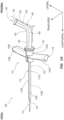
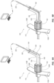
- FIG. 1A depicts a perspective view of a microintroducer system 100 including a microintroducer 110 and adapter 150 in accordance with an embodiment of the disclosure.
- the microintroducer 110 includes an introducer sheath 112 defining a channel 122 extending from a proximal end to a distal end, in which a dilator 114, or similar device can be disposed therein.
- a distal tip of the dilator 114 is shown extending beyond a distal tip of the introducer sheath 112.
- a proximal end of the sheath 112 is shown coupled to a handle 116 (or pair of handles 116, e.g. left and right handle, 116A, 116B).
- the handle can be attached to the sides of the proximal end of the sheath, or the handle can form the proximal end of the channel.
- the handle can be insert molded over the proximal end of the sheath.
- the handle can include a valve. Examples of introducer sheaths, including the configurations of sheaths and handles, are disclosed in U.S. Patent No. 7,637,893 , U.S. Patent No. 8,403,890 , and U.S. Patent No. 8,932,260 .
- the sheath 112 includes breach lines 118A, 118B extending longitudinally along apposing walls of the sheath 112.
- the breach lines 118A, 118B can be scorelines, perforations, laser cut lines, or similar lines of weakness that allow the sheath 112 to be splittable along a longitudinal axis.
- the breach lines 118A, 118B are disposed along opposing walls of the sheath 112 so that sheath 112 is splittable into two substantially equal halves. As shown in FIG. 1A , breach line 118A is disposed on an upper side of the sheath 112 with breach line 118B disposed on a lower side thereof, thus defining a sheath 112 splitable into a left and right portion, 112A, 112B.
- the left sheath portion 112A is coupled with a left handle 116A and the right sheath portion 112B is coupled with a right handle 116B.
- the sheath material e.g., PTFE
- the sheath material can be formed (e.g., extruded) with an alignment of molecules so that the sheath can be peeled at the same or similar circumferential locations without the need for breach lines.
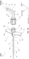
- the adapter 150 can be integral or built into the microintroducer, as shown in FIG. 1A , or could be separately attached, as shown in FIG. 1B .
- the adapter 150 When integral with the microintroducer 110, the adapter 150 includes a distal portion splittable into halves 150A and 15B that are aligned with the breach lines of the sheath 112 and/or the handle 116.
- the microintroducer 110 further includes a connector 120 disposed at a proximal end.
- Connector 120 can include a threaded portion for receiving a corresponding spin nut 152 from adapter 150, as discussed below.
- the connector 120 can be defined by a left and right portion 120A, 120B that are coupled with a proximal portion of the left and right handles 116A, 116B respectively. When assembled, as shown in FIG. 2 , the left and right portions of the connector 120A, 120B define a continuous outer perimeter to allow a corresponding spin nut 152 or similar connector to engage an outer surface thereof.
- the adapter 150 can include an attachment mechanism to couple to the connector.
- the attachment mechanism in one embodiment includes a splittable or breakable portion to permit separation of the adapter 150 after a medical device is inserted therethrough and through the microintroducer into the vasculature of the patient.
- the adapter 150 includes a spin nut 152 configured for engaging threaded connector 120.
- the attachment mechanism corresponds to different types of connectors as noted above.
- the spin nut includes a break line 166 extending axially along a longitudinal axis.
- the break line 166 can include scorelines, perforations, laser cut lines, or similar lines of weakness, as described herein.
- the spin nut 152 includes more than one break line 166, which allows the spin nut to be removed while maintaining an elongate medical device, extending therethrough, in place.
- the adapter 150 includes a distal tube portion 154 that extends along a longitudinal axis of the microintroducer system 100, and in communication with the channel 122, to a predetermined formed angled portion 156 that smoothly curves at an angle to the distal tube portion 154 into a proximal tube portion 158.
- the proximal tube portion 158 extends away from the distal tube portion 154 at an angle to the longitudinal axis of the microintroducer system 100.
- the angled portion 156 can define an angle (" ⁇ ") of between 5° and 175° from the longitudinal axis. In an embodiment, the angle ⁇ is between 45° and 90°, with a preferred embodiment being 70°.
- the elongate tube includes a plurality of curved portions that together define a spiral path along the angled portion and, in some embodiments, also the proximal tube portion.
- Other curved pathways are also contemplated, such as a sinusoidal curve, for example.
- the distal tube portion 154, the angled portion 156, and the proximal tube portion 158 together define a continuous receiver tube 160 of the adapter 150.
- the receiver tube 160 defines a pathway 162 extending therethrough and is fluidly connected to the sheath channel 122 by way of the connector 120 in the illustrated embodiment.
- a proximal end of the receiver tube 160 includes a funnel 164.
- the funnel 164 defines a tapered portion such that a proximal end of the funnel 164 defines a larger diameter than a diameter of the receiver pathway 162.
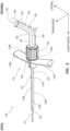
- the receiver tube 160 further includes a breach line 168.
- Breach line 168 extends axially along the receiver tube 160 from the funnel 164 at a proximal end to the spin nut 152 as a distal end.
- the breach line can include scorelines, perforations, laser cut lines, or similar lines of weakness as described herein, that allow the receiver tube 160 to be splittable along an axis of the receiver pathway 162.
- the breach line 168 allows the adapter 150 to be removed while allowing an elongate medical device, extending therethrough to remain in place.
- the receiver tube 160 includes more than one breach line, for example 168A, 168B so that the adapter 150 can be separated into substantially equal portions. Although greater numbers of breach lines 168 defining greater numbers of portions of adapter 150 are also contemplated.
- the receiver tube 160 can include an elongate opening 170 in place of the breach line 168.
- the opening 170 in the embodiment shown in FIG. 3B is a slit such that opposing sides of the receiving tube 160 are in contact with one another.
- the opening 170 extends along lengthwise along at least one side of the receiver tube 160 along an entire length thereof, for example from the funnel 164 at a proximal end to the spin nut 152 as a distal end.
- the opening 170 allows the adapter to be removed while allowing any elongate medical device extending therethrough to remain in place. It will be appreciated that the opening 170 can be disposed at any circumferential location on the receiver tube.
- the opening is shown as an equidistant gap between sides of the receiver tube 160.
- the gap can be tapered, and can be more narrow or wider than shown.
- the microintroducer 110 is used to access a vasculature, or similar area of a patient.
- the microintroducer 110 and dilator 114 are advanced distally until a distal tip 124 of the sheath 112 accesses the vasculature of the patient, or similar area.
- the dilator 114 is then removed and the sheath 112 of the introducer 110 can define an access path for other elongate medical devices to be introduced.
- Such elongate medical devices can include stylets, guidewires, catheters, such as integrated shape sensing catheters, peripheral IV catheter, midline catheter, Peripherally Inserted Central Catheter (PICC), acute or chronic Central Venous Catheter (CVC), and other elongate medical devices that are introduced into a patient.
- PICC Peripherally Inserted Central Catheter
- CVC Central Venous Catheter
- the adapter 150 is then coupled with the connector 120 using spin nut 152 or similar connector.
- the receiver pathway 162 is fluidly connected with the sheath channel 122 to provide an access channel extending from funnel 164 at a proximal end to the sheath tip 124 at a distal end.
- the elongate medical device is then introduced to the vasculature by introducing the device through funnel 164, advancing along receiver pathway 162 / sheath channel 122 to extend beyond the distal tip 124 of sheath 112. With the elongate medical device in place, the microintroducer system 100 can be removed without disturbing the position of the elongate medical devices.
- the adapter 150 is removed by unthreading the spin nut 152 from the connector, after which it is fractured along break line 166 and the receiver tube 160 is separated along breach line 168.
- the spin nut 152 includes two break lines 166 disposed along opposite walls of the spin nut 152 so that the spin nut 152 fractures into two substantially equal portions, these can be separated and removed.
- the user grasps the handles 116A, 116B and separates the handles in a proximal and transversely outward direction. This in turn causes the connector 120 and sheath 112 to separate along breach lines 118A, 118B (or along aligned molecules). This allows the microintroducer 110 to be removed leaving the elongate medical device in place.
- the receiver tube 160 is attached to the connector 120 using adhesive, bonding, welding, or similar suitable methods.
- the receiver tube 160 and connector 120 are formed monolithically as a single structure. Accordingly, removal of the adapter 150 and the microintroducer 110 occurs concurrently. The receiver tube 160 and connector 120 will separate distally along breach line(s) 118 and proximally along breach line(s) 168 as the handles are pulled away from one another. This allows removal of the system 100 while leaving the elongate medical devices in place.
- the adapter 150 includes an elongate opening 170. With the spin nut 152 removed, as described herein, the adapter 150 is removed from the elongate medical device by allowing the elongate medical device to pass transversely, or laterally, through the opening 170, depending on the location of the opening 170. It will be appreciated that the opening may be disposed on an upper, lower, or side portion of the receiver tube 160 without departing from the scope of the present invention.
- the microintroducer 110 can then be removed by separating handles 116, as described herein.
- the adapter 150 including funnel 164, provides a wider opening and a larger target area with which to introduce the elongate medical device. Further, when the microintroducer 110 is introduced to the patient, the microintroducer 110 substantially lies flat against a skin surface of the patient. The angled portion 156 allows the proximal tube portion 158 and funnel 164 to extend away from the skin surface providing a more convenient, open target area with which to introduce a medical device.
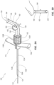
- the angle ⁇ provides a fixed reference angle that can be used as a fiduciary datum or initiation point for a fiber optic stylet 200.
- the microintroducer system 100 With the microintroducer system 100 disposed within a patient and the dilator 114 is removed, the microintroducer system 100 provides an access channel, that of receiver pathway 162 and sheath channel 122.
- the fiber optic stylet 200 can be advanced through the adapter until it is received within the angled portion 156.
- the angled portion 156 then deflects a distal tip 224 the fiber optic stylet 200 at a predetermined angle ⁇ to align a distal portion with a longitudinal axis of the microintroducer 110.
- the fiber optic stylet 200 is communicatively coupled with an external device 250 that detects and records any deflections along a length of the stylet 200.
- the external device 250 can automatically calibrate the deflection in the fiber optic stylet 200 against the known angle ⁇ .
- the fiber optic stylet 200 can also use the deflection of the known angle ⁇ as a start point in the process of shape sensing, such that any deflections detected along the stylet 200 that are distal to the deflection angle ⁇ can be recorded and used to map the path of the stylet 200 through the vasculature of the patient.
- the fiber optic stylet 200 can also use the deflection of the known angle ⁇ as a start point for tracking the length stylet that is inserted into the vasculature of the patient.
- Fiber optic stylet systems such as stylet 200 and external device 250, use the pattern of deflections along the length of the stylet, together with the length of stylet inserted, to determine a 3D map of the vasculature of the patient.
- Using the angled portion 156 of the adapter 150 as a fiduciary point allows the stylet 200 and external device 250 to calibrate the stylet to a reference plane and automatically initiate the mapping software.
- the external device 250 displays, on a user interface, an isometric view of the stylet 200 together with additional imagery of the patient.
- the external device can include a handheld device, laptop, computer station, server, networked device or similar suitable device or devices communicatively coupled together, for receiving information from the stylet 200 and displaying a map of the path taken by the stylet through the vasculature of the patient.
- the external device 250 can further overlay imagery of the patient, the imagery can include CAT scans, PET scans, MRI, x-ray, or the like.
- the fiber optic stylet 200 can be used in conjunction with one or more additional medical devices such as catheters or guidewires associated therewith. Accordingly, as the path of the stylet 200 is mapped, the path of any associated medical device can also be determined.
- the fiber optic stylet system can include more than one stylet communicatively coupled with the external device 250 so as to map more than one path through the vasculature of the patient.
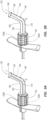
- the adapter 150 can further include an advancement mechanism for the medical device to be inserted through the microintroducer 100.
- the advancement mechanism can be any type of driving mechanism, such as, for example, a slide, screw, crank, etc.
- the advancement mechanism is a scroll wheel as shown in FIGS. 5A-5B .
- the scroll wheel 180 can be disposed within a wall of the adapter 150 so that an edge surface thereof engages an elongate medical device, e.g. stylet 200.
- the stylet 200 can include a stiffening member (not shown).
- the stiffening member can include an elongate member extending longitudinally through or with the stylet 200, in an embodiment the stiffening member is co-extruded with the stylet 200.
- the stiffening member can include a material, such as a metal or similar alternative material, which displays stiffer mechanical properties that the stylet 200 and can further prevent the stylet 200 from buckling or kinking.
- the scroll wheel 180 rotates about a central point 182. As shown in FIG. 5B , a user manipulates an edge surface of the scroll wheel 180 that extends beyond an outer wall of the adapter 150 and is opposite that of the edge surface engaging the stylet 200. As the scroll wheel 180 is rotated, the stylet 200 is moved through the receiver pathway 162. As shown in FIG. 5A the scroll wheel 180 is position adjacent the angled portion 156 although other positions along the adapter 150 are also contemplated.
- FIG. 5B shows a side profile of scroll wheel 180.
- the side surface defines a concave surface to engage a side surface of an elongate medical device, e.g. stylet 200.
- the scroll wheel 180 can include gripping features 184 such as ridges which can be formed monolithically with the scroll wheel 180, or be formed of a separate material displaying different characteristics.
- gripping feature 184 can include a silicone rubber ring disposed about a side surface to aide engagement, not only of the stylet 200 but also for the user manipulating the opposite side.
- the scroll wheel 180 can further include a ball plunger and detent mechanism, or ratchet mechanism to provide a graduated rotation. This allows a user to rotate the scroll wheel 180 at set intervals and in turn advance or retract the stylet 200 at set distance intervals.
- the scroll wheel 180 can allow a user to advance or retract the elongate medical device through the adapter 150 at a controlled rate. This prevents the stylet 200 from being advanced/retracted too quickly or at inconsistent rates. Further the scroll wheel 180 can prevent buckling of the medical device by pulling the elongate medical device through the adapter 150. As the elongate medical device is introduced to the adapter 150 a distal end engages the gripping features 184 of the scroll wheel 180 prior to engaging the angled portion 156. The scroll wheel 180 can maintain a tension on the stylet 200, or similar elongate medical device, and pull the device through the adapter 150 and about the known angle O of the angled portion 156.
- a distal tip could potentially impinge on an inner wall of the angled portion 156 causing friction therebetween and buckling or kinking the device at a point proximal thereof.
- the scroll wheel 180 can also apply a known, fixed strain on the elongate medical device. Where the stylet 200 detects deflections and strain forces applied along a length thereof, the known, fixed strain applied by the scroll wheel 180 can be accounted for and filtered from the results by the external device 250. This prevents the inconsistent strains and deflections of a user directly engaging the stylet 200 affecting the shape sensing results.
- the scroll wheel 180 can also provide a fiduciary point of known angle of deflection O for a calibration point and starting point for the shape sensing stylet 200, as described herein.
Landscapes
- Health & Medical Sciences (AREA)
- Life Sciences & Earth Sciences (AREA)
- Animal Behavior & Ethology (AREA)
- Veterinary Medicine (AREA)
- Public Health (AREA)
- General Health & Medical Sciences (AREA)
- Engineering & Computer Science (AREA)
- Heart & Thoracic Surgery (AREA)
- Biomedical Technology (AREA)
- Surgery (AREA)
- Pathology (AREA)
- Medical Informatics (AREA)
- Molecular Biology (AREA)
- Biophysics (AREA)
- Anesthesiology (AREA)
- Hematology (AREA)
- Nuclear Medicine, Radiotherapy & Molecular Imaging (AREA)
- Physics & Mathematics (AREA)
- Pulmonology (AREA)
- Gastroenterology & Hepatology (AREA)
- Human Computer Interaction (AREA)
- Media Introduction/Drainage Providing Device (AREA)
- Infusion, Injection, And Reservoir Apparatuses (AREA)
Claims (14)
- Mikroeinführungssystem (100), umfassend:eine Mikroeinführungsvorrichtung (110), die eine Einführungsschleuse (112) einschließt, die mit einem Griff (116) gekoppelt ist, wobei der Griff (116) und die Einführungsschleuse (112) einen Kanal (122) dort hindurch definieren; undeinen Adapter (150), der ein Aufnahmerohr (160) umfasst, das einen vorbestimmten abgewinkelten Abschnitt (156) aufweist, wobei das Aufnahmerohr (160) einen Pfad (162) von einer proximalen Öffnung zu dem Kanal (122) der Mikroeinführungsvorrichtung (110) definiert,wobei der Adapter (150) einen distalen Rohrabschnitt (154) einschließt, der sich entlang einer Längsachse des Mikroeinführungssystems (100) erstreckt und mit dem Kanal (122) in Verbindung steht, bis zu dem vorbestimmten abgewinkelten Abschnitt (156), der sich gleichmäßig in einem Winkel zu dem distalen Rohrabschnitt (154) in einen proximalen Rohrabschnitt (158) krümmt, wobei der Adapter (150) entlang einer Bruchlinie (168), die sich entlang einer gesamten Länge des Adapters (150) erstreckt, teilbar ist.
- Mikroeinführungssystem (100), umfassend:eine Mikroeinführungsvorrichtung (110), die eine Einführungsschleuse (112) einschließt, die mit einem Griff (116) gekoppelt ist, wobei der Griff (116) und die Einführungsschleuse (112) einen Kanal (122) dort hindurch definieren; undeinen Adapter (150), der ein Aufnahmerohr (160) umfasst, das einen vorbestimmten abgewinkelten Abschnitt (156) aufweist, wobei das Aufnahmerohr (160) einen Pfad (162) von einer proximalen Öffnung zu dem Kanal (122) der Mikroeinführungsvorrichtung (110) definiert,wobei der Adapter (150) einen distalen Rohrabschnitt (154) einschließt, der sich entlang einer Längsachse des Mikroeinführungssystems (100) erstreckt und mit dem Kanal (122) in Verbindung steht, bis zu dem vorbestimmten abgewinkelten Abschnitt (156), der sich gleichmäßig in einem Winkel zu dem distalen Rohrabschnitt (154) in einen proximalen Rohrabschnitt (158) krümmt,wobei der Adapter (150) eine Längsöffnung (170) einschließt, die sich entlang einer gesamten Länge des Aufnahmerohrs (160) erstreckt.
- Mikroeinführungssystem (100) nach Anspruch 2, wobei die Längsöffnung (170) einen Schlitz umfasst.
- Mikroeinführungssystem (100) nach einem der Ansprüche 1-3, wobei der Adapter (150) mit der Mikroeinführungsvorrichtung (110) integral ist.
- Mikroeinführungssystem (100) nach einem der Ansprüche 1-4, wobei der vorbestimmte abgewinkelte Abschnitt (156) eine Vielzahl von gekrümmten Abschnitten einschließt.
- Mikroeinführungssystem (100) nach Anspruch 5, wobei der Pfad (162) spiralförmig ist.
- Mikroeinführungssystem (100) nach einem der Ansprüche 1-6, wobei der vorbestimmte abgewinkelte Abschnitt (156) mit der Längsachse des Mikroeinführungssystems (100) einen Winkel zwischen 45° und 90° bildet, wobei der Winkel vorzugsweise etwa 70° beträgt.
- Mikroeinführungssystem (100) nach einem der Ansprüche 1, 2 und 4-7, wobei das Mikroeinführungssystem (110) einen proximalen Verbinder (120) einschließt, und wobei der Adapter (150) einen Befestigungsmechanismus einschließt, der konfiguriert ist, um mit dem proximalen Verbinder (120) zu koppeln.
- Mikroeinführungssystem (100) nach einem der Ansprüche 1-8, wobei der Adapter (150) einen Vorschubmechanismus einschließt, der in einer Wand des Aufnahmerohrs (160) angeordnet ist, wobei der Vorschubmechanismus konfiguriert ist, um eine medizinische Vorrichtung durch das Mikroeinführungssystem (100) zu bewegen.
- Mikroeinführungssystem (100) nach Anspruch 9, wobei der Vorschubmechanismus ein Scrollrad (180) ist, wobei das Scrollrad (180) vorzugsweise benachbart zu dem vorbestimmten abgewinkelten Abschnitt (156) angeordnet ist.
- Mikroeinführungssystem (100) nach einem der Ansprüche 1-10, weiter umfassend ein formabtastendes Mandrinsystem.
- Mikroeinführungssystem (100) nach Anspruch 11, wobei das formabtastende Mandrinsystem einen formabtastenden Mandrin (200) und eine externe Vorrichtung (250), die mit dem formabtastenden Mandrin (200) in Verbindung steht, umfasst.
- Mikroeinführungssystem (100) nach Anspruch 12, wobei der vorbestimmte abgewinkelte Abschnitt (156) einen Kalibrierungspunkt für den formabtastenden Mandrin (200) bereitstellt.
- Mikroeinführungssystem (100) nach Anspruch 12, wobei der Adapter (150) einen Vorschubmechanismus einschließt, und wobei der Vorschubmechanismus einen Referenzpunkt für die externe Vorrichtung (250) bereitstellt, um mit der Messung eines von einem Ablenkungsmuster oder einer eingesetzten Länge des formabtastenden Mandrins (200) zu beginnen.
Applications Claiming Priority (2)
| Application Number | Priority Date | Filing Date | Title |
|---|---|---|---|
| US201962860569P | 2019-06-12 | 2019-06-12 | |
| PCT/US2020/035754 WO2020251806A1 (en) | 2019-06-12 | 2020-06-02 | Microintroducer system |
Publications (4)
| Publication Number | Publication Date |
|---|---|
| EP3979930A1 EP3979930A1 (de) | 2022-04-13 |
| EP3979930A4 EP3979930A4 (de) | 2023-06-07 |
| EP3979930C0 EP3979930C0 (de) | 2024-08-21 |
| EP3979930B1 true EP3979930B1 (de) | 2024-08-21 |
Family
ID=73735892
Family Applications (1)
| Application Number | Title | Priority Date | Filing Date |
|---|---|---|---|
| EP20821927.9A Active EP3979930B1 (de) | 2019-06-12 | 2020-06-02 | Mikroeinführungssystem |
Country Status (6)
| Country | Link |
|---|---|
| US (1) | US20200390467A1 (de) |
| EP (1) | EP3979930B1 (de) |
| JP (1) | JP7617039B2 (de) |
| CN (2) | CN212816220U (de) |
| CA (1) | CA3141903A1 (de) |
| WO (1) | WO2020251806A1 (de) |
Families Citing this family (3)
| Publication number | Priority date | Publication date | Assignee | Title |
|---|---|---|---|---|
| CA3141903A1 (en) * | 2019-06-12 | 2020-12-17 | Bard Access Systems, Inc. | Microintroducer system |
| US20240226504A1 (en) * | 2023-01-10 | 2024-07-11 | Bard Access Systems, Inc. | Adjustable Elongate Medical Device Handle |
| WO2025221201A1 (en) * | 2024-04-18 | 2025-10-23 | Neuronano Ab | Protective assembly for insertion of medical objects into soft |
Family Cites Families (26)
| Publication number | Priority date | Publication date | Assignee | Title |
|---|---|---|---|---|
| US6652492B1 (en) * | 1991-12-13 | 2003-11-25 | Endovascular Technologies, Inc. | Dual valve, flexible sheath and method |
| US5250033A (en) * | 1992-10-28 | 1993-10-05 | Interventional Thermodynamics, Inc. | Peel-away introducer sheath having proximal fitting |
| US5755702A (en) * | 1994-04-21 | 1998-05-26 | Novoste Corporation | Adjustable angular sheath introducer |
| EP0902652B1 (de) * | 1994-07-11 | 2001-03-28 | Karl Storz GmbH & Co. KG | Medizinisches instrument mit einem manipulator |
| US6159198A (en) * | 1998-07-16 | 2000-12-12 | Medtronic, Inc. | Introducer system |
| DE60023702T2 (de) * | 1999-07-06 | 2006-07-20 | Medtronic, Inc., Minneapolis | System zum einführen von kathetern |
| US20040102804A1 (en) * | 1999-08-10 | 2004-05-27 | Chin Albert K. | Apparatus and methods for endoscopic surgical procedures |
| JP2004121553A (ja) * | 2002-10-02 | 2004-04-22 | Terumo Corp | 加熱治療装置 |
| US7104399B2 (en) * | 2004-03-18 | 2006-09-12 | Medtronic Vascular, Inc. | Packaging assembly for a catheter |
| US7367980B2 (en) * | 2004-04-28 | 2008-05-06 | Boston Scientific Scimed, Inc. | Introducer sheath stabilizer |
| US8926564B2 (en) * | 2004-11-29 | 2015-01-06 | C. R. Bard, Inc. | Catheter introducer including a valve and valve actuator |
| US8403890B2 (en) * | 2004-11-29 | 2013-03-26 | C. R. Bard, Inc. | Reduced friction catheter introducer and method of manufacturing and using the same |
| EP1951360B1 (de) * | 2005-11-07 | 2013-09-25 | Flexicath Ltd. | Entfernbarer Adapter für ein trennbares Einführgerät |
| US9028466B2 (en) * | 2009-06-08 | 2015-05-12 | St. Jude Medical Coordination Center Bvba | Adapter for use in connecting to a first percutaneous introducer |
| US20120157854A1 (en) * | 2010-12-15 | 2012-06-21 | Cook Incorporated | System and method for gaining percutaneous access to a body lumen |
| EP2842590A1 (de) * | 2013-09-03 | 2015-03-04 | Coloplast A/S | Zugriffsschaft |
| EP3052021A2 (de) | 2013-10-02 | 2016-08-10 | Koninklijke Philips N.V. | Nabenentwurf und verfahren zur optischen formmessungsregistrierung |
| US20160228200A1 (en) * | 2013-10-02 | 2016-08-11 | Koninklijke Philips N.V. | Device tracking using longitudinal encoding |
| US9789289B2 (en) * | 2014-04-23 | 2017-10-17 | Becton, Dickinson And Company | Systems and methods for providing an integrated package and grip for catheter |
| WO2016033143A1 (en) | 2014-08-26 | 2016-03-03 | Velano Vascular, Inc. | Systems and methods for phlebotomy through a peripheral iv catheter |
| WO2016088037A1 (en) * | 2014-12-02 | 2016-06-09 | Koninklijke Philips N.V. | Automatic tracking and registration of ultrasound probe using optical shape sensing without tip fixation |
| US10549072B2 (en) * | 2015-10-28 | 2020-02-04 | Becton, Dickinson And Company | Integrated catheter with independent fluid paths |
| EP3547946B1 (de) * | 2016-12-05 | 2025-08-13 | Koninklijke Philips N.V. | Systeme zur bestimmung der länge einer interventionellen vorrichtung ohne formerfassung mit einem formerfassten führungsdraht |
| US11027105B2 (en) * | 2017-07-13 | 2021-06-08 | Biosense Webster (Israel) Ltd. | Adjustable instrument for dilation of anatomical passageway |
| CN111032140B (zh) * | 2017-08-16 | 2022-08-16 | 直观外科手术操作公司 | 用于在医疗程序期间监测患者运动的系统和方法 |
| CA3141903A1 (en) * | 2019-06-12 | 2020-12-17 | Bard Access Systems, Inc. | Microintroducer system |
-
2020
- 2020-06-02 CA CA3141903A patent/CA3141903A1/en active Pending
- 2020-06-02 US US16/890,840 patent/US20200390467A1/en active Pending
- 2020-06-02 EP EP20821927.9A patent/EP3979930B1/de active Active
- 2020-06-02 WO PCT/US2020/035754 patent/WO2020251806A1/en not_active Ceased
- 2020-06-02 JP JP2021573584A patent/JP7617039B2/ja active Active
- 2020-06-02 CN CN202020981849.2U patent/CN212816220U/zh active Active
- 2020-06-02 CN CN202010489604.2A patent/CN112075923B/zh active Active
Also Published As
| Publication number | Publication date |
|---|---|
| WO2020251806A1 (en) | 2020-12-17 |
| CN112075923B (zh) | 2025-11-14 |
| US20200390467A1 (en) | 2020-12-17 |
| CA3141903A1 (en) | 2020-12-17 |
| CN212816220U (zh) | 2021-03-30 |
| JP7617039B2 (ja) | 2025-01-17 |
| EP3979930A1 (de) | 2022-04-13 |
| CN112075923A (zh) | 2020-12-15 |
| JP2022536908A (ja) | 2022-08-22 |
| EP3979930A4 (de) | 2023-06-07 |
| EP3979930C0 (de) | 2024-08-21 |
Similar Documents
| Publication | Publication Date | Title |
|---|---|---|
| US11253277B2 (en) | Systems for accessing a central pulmonary artery | |
| EP3979930B1 (de) | Mikroeinführungssystem | |
| US6363273B1 (en) | Introducer element and method of using same | |
| EP3071283B1 (de) | Sensorbefestigungsanordnung für führungsdraht mit sensor und zugehörige vorrichtungen, systeme und verfahren | |
| US5782807A (en) | Releasably locking introducer devices | |
| US5902274A (en) | Catheter assembly | |
| EP2598194B1 (de) | Medizinische freisetzungssystem | |
| US5843002A (en) | Guide wire dispenser apparatus and method | |
| US9155868B2 (en) | Delivery catheter apparatus and methods | |
| US20020107482A1 (en) | Introducer with multiple sheaths and method of use therfor | |
| US20110087261A1 (en) | Device and Method for Transseptal Puncturing | |
| EP3436130B1 (de) | Drehmomentvorrichtungen zur verwendung mit intravaskulären vorrichtungen und zugehörige systeme und verfahren | |
| US20140276660A1 (en) | Fluid drain tube with tissue oxygenation content sensor | |
| US20220280185A1 (en) | Catheter devices, needle assemblies, kits and methods | |
| JP2003508167A (ja) | カテーテルの位置決め装置 | |
| AU2006252726B2 (en) | Low profile introducer apparatus | |
| EP0556618B1 (de) | Chirurgischer Dilator | |
| EP3965861B1 (de) | Drainagekatheteraustauschsystem | |
| EP2555823A1 (de) | Klemme für schleifenspitzenvorrichtungen | |
| US20230372686A1 (en) | Apparatus and method for dilating a blood vessel and subcutaneous tissue | |
| US20230233798A1 (en) | Catheter Insertion System | |
| JP2009232988A (ja) | 外套付硬膜外針 |
Legal Events
| Date | Code | Title | Description |
|---|---|---|---|
| STAA | Information on the status of an ep patent application or granted ep patent |
Free format text: STATUS: THE INTERNATIONAL PUBLICATION HAS BEEN MADE |
|
| PUAI | Public reference made under article 153(3) epc to a published international application that has entered the european phase |
Free format text: ORIGINAL CODE: 0009012 |
|
| STAA | Information on the status of an ep patent application or granted ep patent |
Free format text: STATUS: REQUEST FOR EXAMINATION WAS MADE |
|
| 17P | Request for examination filed |
Effective date: 20220105 |
|
| AK | Designated contracting states |
Kind code of ref document: A1 Designated state(s): AL AT BE BG CH CY CZ DE DK EE ES FI FR GB GR HR HU IE IS IT LI LT LU LV MC MK MT NL NO PL PT RO RS SE SI SK SM TR |
|
| DAV | Request for validation of the european patent (deleted) | ||
| DAX | Request for extension of the european patent (deleted) | ||
| A4 | Supplementary search report drawn up and despatched |
Effective date: 20230511 |
|
| RIC1 | Information provided on ipc code assigned before grant |
Ipc: A61B 34/20 20160101ALN20230504BHEP Ipc: A61M 29/00 20060101ALI20230504BHEP Ipc: A61M 25/01 20060101ALI20230504BHEP Ipc: A61B 5/06 20060101ALI20230504BHEP Ipc: A61M 25/06 20060101ALI20230504BHEP Ipc: A61M 39/12 20060101ALI20230504BHEP Ipc: A61M 39/10 20060101ALI20230504BHEP Ipc: A61B 17/06 20060101ALI20230504BHEP Ipc: A61B 17/34 20060101AFI20230504BHEP |
|
| GRAP | Despatch of communication of intention to grant a patent |
Free format text: ORIGINAL CODE: EPIDOSNIGR1 |
|
| STAA | Information on the status of an ep patent application or granted ep patent |
Free format text: STATUS: GRANT OF PATENT IS INTENDED |
|
| RIC1 | Information provided on ipc code assigned before grant |
Ipc: A61B 5/00 20060101ALN20240222BHEP Ipc: A61B 34/20 20160101ALN20240222BHEP Ipc: A61M 29/00 20060101ALI20240222BHEP Ipc: A61M 25/01 20060101ALI20240222BHEP Ipc: A61B 5/06 20060101ALI20240222BHEP Ipc: A61M 25/06 20060101ALI20240222BHEP Ipc: A61M 39/12 20060101ALI20240222BHEP Ipc: A61M 39/10 20060101ALI20240222BHEP Ipc: A61B 17/06 20060101ALI20240222BHEP Ipc: A61B 17/34 20060101AFI20240222BHEP |
|
| INTG | Intention to grant announced |
Effective date: 20240321 |
|
| GRAS | Grant fee paid |
Free format text: ORIGINAL CODE: EPIDOSNIGR3 |
|
| GRAA | (expected) grant |
Free format text: ORIGINAL CODE: 0009210 |
|
| STAA | Information on the status of an ep patent application or granted ep patent |
Free format text: STATUS: THE PATENT HAS BEEN GRANTED |
|
| AK | Designated contracting states |
Kind code of ref document: B1 Designated state(s): AL AT BE BG CH CY CZ DE DK EE ES FI FR GB GR HR HU IE IS IT LI LT LU LV MC MK MT NL NO PL PT RO RS SE SI SK SM TR |
|
| REG | Reference to a national code |
Ref country code: GB Ref legal event code: FG4D |
|
| REG | Reference to a national code |
Ref country code: CH Ref legal event code: EP |
|
| REG | Reference to a national code |
Ref country code: IE Ref legal event code: FG4D |
|
| REG | Reference to a national code |
Ref country code: DE Ref legal event code: R096 Ref document number: 602020036355 Country of ref document: DE |
|
| U01 | Request for unitary effect filed |
Effective date: 20240904 |
|
| U07 | Unitary effect registered |
Designated state(s): AT BE BG DE DK EE FI FR IT LT LU LV MT NL PT RO SE SI Effective date: 20240923 |
|
| PG25 | Lapsed in a contracting state [announced via postgrant information from national office to epo] |
Ref country code: NO Free format text: LAPSE BECAUSE OF FAILURE TO SUBMIT A TRANSLATION OF THE DESCRIPTION OR TO PAY THE FEE WITHIN THE PRESCRIBED TIME-LIMIT Effective date: 20241121 |
|
| PG25 | Lapsed in a contracting state [announced via postgrant information from national office to epo] |
Ref country code: PL Free format text: LAPSE BECAUSE OF FAILURE TO SUBMIT A TRANSLATION OF THE DESCRIPTION OR TO PAY THE FEE WITHIN THE PRESCRIBED TIME-LIMIT Effective date: 20240821 Ref country code: GR Free format text: LAPSE BECAUSE OF FAILURE TO SUBMIT A TRANSLATION OF THE DESCRIPTION OR TO PAY THE FEE WITHIN THE PRESCRIBED TIME-LIMIT Effective date: 20241122 |
|
| PG25 | Lapsed in a contracting state [announced via postgrant information from national office to epo] |
Ref country code: IS Free format text: LAPSE BECAUSE OF FAILURE TO SUBMIT A TRANSLATION OF THE DESCRIPTION OR TO PAY THE FEE WITHIN THE PRESCRIBED TIME-LIMIT Effective date: 20241221 |
|
| PG25 | Lapsed in a contracting state [announced via postgrant information from national office to epo] |
Ref country code: HR Free format text: LAPSE BECAUSE OF FAILURE TO SUBMIT A TRANSLATION OF THE DESCRIPTION OR TO PAY THE FEE WITHIN THE PRESCRIBED TIME-LIMIT Effective date: 20240821 |
|
| PG25 | Lapsed in a contracting state [announced via postgrant information from national office to epo] |
Ref country code: RS Free format text: LAPSE BECAUSE OF FAILURE TO SUBMIT A TRANSLATION OF THE DESCRIPTION OR TO PAY THE FEE WITHIN THE PRESCRIBED TIME-LIMIT Effective date: 20241121 Ref country code: ES Free format text: LAPSE BECAUSE OF FAILURE TO SUBMIT A TRANSLATION OF THE DESCRIPTION OR TO PAY THE FEE WITHIN THE PRESCRIBED TIME-LIMIT Effective date: 20240821 |
|
| PG25 | Lapsed in a contracting state [announced via postgrant information from national office to epo] |
Ref country code: RS Free format text: LAPSE BECAUSE OF FAILURE TO SUBMIT A TRANSLATION OF THE DESCRIPTION OR TO PAY THE FEE WITHIN THE PRESCRIBED TIME-LIMIT Effective date: 20241121 Ref country code: PL Free format text: LAPSE BECAUSE OF FAILURE TO SUBMIT A TRANSLATION OF THE DESCRIPTION OR TO PAY THE FEE WITHIN THE PRESCRIBED TIME-LIMIT Effective date: 20240821 Ref country code: NO Free format text: LAPSE BECAUSE OF FAILURE TO SUBMIT A TRANSLATION OF THE DESCRIPTION OR TO PAY THE FEE WITHIN THE PRESCRIBED TIME-LIMIT Effective date: 20241121 Ref country code: IS Free format text: LAPSE BECAUSE OF FAILURE TO SUBMIT A TRANSLATION OF THE DESCRIPTION OR TO PAY THE FEE WITHIN THE PRESCRIBED TIME-LIMIT Effective date: 20241221 Ref country code: HR Free format text: LAPSE BECAUSE OF FAILURE TO SUBMIT A TRANSLATION OF THE DESCRIPTION OR TO PAY THE FEE WITHIN THE PRESCRIBED TIME-LIMIT Effective date: 20240821 Ref country code: GR Free format text: LAPSE BECAUSE OF FAILURE TO SUBMIT A TRANSLATION OF THE DESCRIPTION OR TO PAY THE FEE WITHIN THE PRESCRIBED TIME-LIMIT Effective date: 20241122 Ref country code: ES Free format text: LAPSE BECAUSE OF FAILURE TO SUBMIT A TRANSLATION OF THE DESCRIPTION OR TO PAY THE FEE WITHIN THE PRESCRIBED TIME-LIMIT Effective date: 20240821 |
|
| PG25 | Lapsed in a contracting state [announced via postgrant information from national office to epo] |
Ref country code: SM Free format text: LAPSE BECAUSE OF FAILURE TO SUBMIT A TRANSLATION OF THE DESCRIPTION OR TO PAY THE FEE WITHIN THE PRESCRIBED TIME-LIMIT Effective date: 20240821 |
|
| PG25 | Lapsed in a contracting state [announced via postgrant information from national office to epo] |
Ref country code: CZ Free format text: LAPSE BECAUSE OF FAILURE TO SUBMIT A TRANSLATION OF THE DESCRIPTION OR TO PAY THE FEE WITHIN THE PRESCRIBED TIME-LIMIT Effective date: 20240821 |
|
| PG25 | Lapsed in a contracting state [announced via postgrant information from national office to epo] |
Ref country code: SK Free format text: LAPSE BECAUSE OF FAILURE TO SUBMIT A TRANSLATION OF THE DESCRIPTION OR TO PAY THE FEE WITHIN THE PRESCRIBED TIME-LIMIT Effective date: 20240821 |
|
| U20 | Renewal fee for the european patent with unitary effect paid |
Year of fee payment: 6 Effective date: 20250520 |
|
| PLBE | No opposition filed within time limit |
Free format text: ORIGINAL CODE: 0009261 |
|
| STAA | Information on the status of an ep patent application or granted ep patent |
Free format text: STATUS: NO OPPOSITION FILED WITHIN TIME LIMIT |
|
| PGFP | Annual fee paid to national office [announced via postgrant information from national office to epo] |
Ref country code: GB Payment date: 20250520 Year of fee payment: 6 |
|
| 26N | No opposition filed |
Effective date: 20250522 |
|
| REG | Reference to a national code |
Ref country code: CH Ref legal event code: H13 Free format text: ST27 STATUS EVENT CODE: U-0-0-H10-H13 (AS PROVIDED BY THE NATIONAL OFFICE) Effective date: 20260127 |
|
| PG25 | Lapsed in a contracting state [announced via postgrant information from national office to epo] |
Ref country code: MC Free format text: LAPSE BECAUSE OF FAILURE TO SUBMIT A TRANSLATION OF THE DESCRIPTION OR TO PAY THE FEE WITHIN THE PRESCRIBED TIME-LIMIT Effective date: 20240821 |