EP1746632B1 - Gesinterte elektrode zur verwendung in kaltkathodenröhren, mit dieser gesinterten elektrode zur verwendung in kaltkathodenröhren ausgestattete kaltkathodenröhre und flüssigkristall-display-einheit - Google Patents
Gesinterte elektrode zur verwendung in kaltkathodenröhren, mit dieser gesinterten elektrode zur verwendung in kaltkathodenröhren ausgestattete kaltkathodenröhre und flüssigkristall-display-einheit Download PDFInfo
- Publication number
- EP1746632B1 EP1746632B1 EP05737302A EP05737302A EP1746632B1 EP 1746632 B1 EP1746632 B1 EP 1746632B1 EP 05737302 A EP05737302 A EP 05737302A EP 05737302 A EP05737302 A EP 05737302A EP 1746632 B1 EP1746632 B1 EP 1746632B1
- Authority
- EP
- European Patent Office
- Prior art keywords
- cathode tube
- cold cathode
- sintered electrode
- electrode
- tube according
- Prior art date
- Legal status (The legal status is an assumption and is not a legal conclusion. Google has not performed a legal analysis and makes no representation as to the accuracy of the status listed.)
- Active
Links
- 239000004973 liquid crystal related substance Substances 0.000 title claims abstract description 33
- 230000003746 surface roughness Effects 0.000 claims abstract description 26
- 239000010955 niobium Substances 0.000 claims description 43
- 150000001875 compounds Chemical class 0.000 claims description 36
- 229910052799 carbon Inorganic materials 0.000 claims description 35
- 229910052760 oxygen Inorganic materials 0.000 claims description 33
- 239000001301 oxygen Substances 0.000 claims description 33
- 229910052761 rare earth metal Inorganic materials 0.000 claims description 31
- 239000000463 material Substances 0.000 claims description 26
- 229910052751 metal Inorganic materials 0.000 claims description 21
- 239000002184 metal Substances 0.000 claims description 20
- WABPQHHGFIMREM-UHFFFAOYSA-N lead(0) Chemical compound [Pb] WABPQHHGFIMREM-UHFFFAOYSA-N 0.000 claims description 18
- OKTJSMMVPCPJKN-UHFFFAOYSA-N Carbon Chemical compound [C] OKTJSMMVPCPJKN-UHFFFAOYSA-N 0.000 claims description 17
- 239000002245 particle Substances 0.000 claims description 17
- ZOKXTWBITQBERF-UHFFFAOYSA-N Molybdenum Chemical compound [Mo] ZOKXTWBITQBERF-UHFFFAOYSA-N 0.000 claims description 16
- QVGXLLKOCUKJST-UHFFFAOYSA-N atomic oxygen Chemical compound [O] QVGXLLKOCUKJST-UHFFFAOYSA-N 0.000 claims description 16
- 229910052750 molybdenum Inorganic materials 0.000 claims description 13
- 239000010936 titanium Substances 0.000 claims description 13
- 239000011733 molybdenum Substances 0.000 claims description 11
- 238000002844 melting Methods 0.000 claims description 8
- 229910045601 alloy Inorganic materials 0.000 claims description 6
- 239000000956 alloy Substances 0.000 claims description 6
- 229910052721 tungsten Inorganic materials 0.000 claims description 6
- 229910052758 niobium Inorganic materials 0.000 claims description 5
- GUCVJGMIXFAOAE-UHFFFAOYSA-N niobium atom Chemical compound [Nb] GUCVJGMIXFAOAE-UHFFFAOYSA-N 0.000 claims description 5
- WFKWXMTUELFFGS-UHFFFAOYSA-N tungsten Chemical compound [W] WFKWXMTUELFFGS-UHFFFAOYSA-N 0.000 claims description 4
- 239000010937 tungsten Substances 0.000 claims description 4
- RTAQQCXQSZGOHL-UHFFFAOYSA-N Titanium Chemical compound [Ti] RTAQQCXQSZGOHL-UHFFFAOYSA-N 0.000 claims description 3
- 229910052702 rhenium Inorganic materials 0.000 claims description 3
- WUAPFZMCVAUBPE-UHFFFAOYSA-N rhenium atom Chemical compound [Re] WUAPFZMCVAUBPE-UHFFFAOYSA-N 0.000 claims description 3
- 229910052716 thallium Inorganic materials 0.000 claims description 3
- BKVIYDNLLOSFOA-UHFFFAOYSA-N thallium Chemical compound [Tl] BKVIYDNLLOSFOA-UHFFFAOYSA-N 0.000 claims description 3
- 229910052719 titanium Inorganic materials 0.000 claims description 3
- 239000000126 substance Substances 0.000 abstract description 6
- 230000000052 comparative effect Effects 0.000 description 43
- 229910052753 mercury Inorganic materials 0.000 description 35
- QSHDDOUJBYECFT-UHFFFAOYSA-N mercury Chemical compound [Hg] QSHDDOUJBYECFT-UHFFFAOYSA-N 0.000 description 34
- PXHVJJICTQNCMI-UHFFFAOYSA-N Nickel Chemical compound [Ni] PXHVJJICTQNCMI-UHFFFAOYSA-N 0.000 description 17
- 238000004519 manufacturing process Methods 0.000 description 16
- 238000010586 diagram Methods 0.000 description 14
- 238000004544 sputter deposition Methods 0.000 description 14
- 238000005259 measurement Methods 0.000 description 13
- 239000000203 mixture Substances 0.000 description 13
- 238000003466 welding Methods 0.000 description 12
- 230000000694 effects Effects 0.000 description 10
- 239000007789 gas Substances 0.000 description 10
- 238000005238 degreasing Methods 0.000 description 8
- 239000000843 powder Substances 0.000 description 8
- 239000000470 constituent Substances 0.000 description 7
- 239000011521 glass Substances 0.000 description 7
- 229910052759 nickel Inorganic materials 0.000 description 7
- 238000005245 sintering Methods 0.000 description 7
- XKRFYHLGVUSROY-UHFFFAOYSA-N Argon Chemical compound [Ar] XKRFYHLGVUSROY-UHFFFAOYSA-N 0.000 description 6
- 238000000034 method Methods 0.000 description 6
- 239000002994 raw material Substances 0.000 description 6
- 239000000523 sample Substances 0.000 description 6
- 230000015572 biosynthetic process Effects 0.000 description 5
- 229910052746 lanthanum Inorganic materials 0.000 description 5
- FZLIPJUXYLNCLC-UHFFFAOYSA-N lanthanum atom Chemical compound [La] FZLIPJUXYLNCLC-UHFFFAOYSA-N 0.000 description 5
- 238000013507 mapping Methods 0.000 description 5
- 230000001012 protector Effects 0.000 description 5
- 230000009467 reduction Effects 0.000 description 5
- 230000001105 regulatory effect Effects 0.000 description 5
- UFHFLCQGNIYNRP-UHFFFAOYSA-N Hydrogen Chemical compound [H][H] UFHFLCQGNIYNRP-UHFFFAOYSA-N 0.000 description 4
- 239000004372 Polyvinyl alcohol Substances 0.000 description 4
- 238000011156 evaluation Methods 0.000 description 4
- 239000011888 foil Substances 0.000 description 4
- 239000001257 hydrogen Substances 0.000 description 4
- 229910052739 hydrogen Inorganic materials 0.000 description 4
- 229920002451 polyvinyl alcohol Polymers 0.000 description 4
- 150000002910 rare earth metals Chemical class 0.000 description 4
- 229910000497 Amalgam Inorganic materials 0.000 description 3
- 229910052684 Cerium Inorganic materials 0.000 description 3
- WHXSMMKQMYFTQS-UHFFFAOYSA-N Lithium Chemical compound [Li] WHXSMMKQMYFTQS-UHFFFAOYSA-N 0.000 description 3
- 238000004458 analytical method Methods 0.000 description 3
- 238000000137 annealing Methods 0.000 description 3
- 229910052786 argon Inorganic materials 0.000 description 3
- 239000011230 binding agent Substances 0.000 description 3
- 239000011575 calcium Substances 0.000 description 3
- GWXLDORMOJMVQZ-UHFFFAOYSA-N cerium Chemical compound [Ce] GWXLDORMOJMVQZ-UHFFFAOYSA-N 0.000 description 3
- 238000010276 construction Methods 0.000 description 3
- 238000005336 cracking Methods 0.000 description 3
- 239000008187 granular material Substances 0.000 description 3
- 238000001746 injection moulding Methods 0.000 description 3
- 229910000833 kovar Inorganic materials 0.000 description 3
- 229910052744 lithium Inorganic materials 0.000 description 3
- 150000002739 metals Chemical class 0.000 description 3
- 238000000465 moulding Methods 0.000 description 3
- 229910052754 neon Inorganic materials 0.000 description 3
- GKAOGPIIYCISHV-UHFFFAOYSA-N neon atom Chemical compound [Ne] GKAOGPIIYCISHV-UHFFFAOYSA-N 0.000 description 3
- 238000012545 processing Methods 0.000 description 3
- -1 rare earth compound Chemical class 0.000 description 3
- 238000001953 recrystallisation Methods 0.000 description 3
- 238000005406 washing Methods 0.000 description 3
- JVKRKMWZYMKVTQ-UHFFFAOYSA-N 2-[4-[2-(2,3-dihydro-1H-inden-2-ylamino)pyrimidin-5-yl]pyrazol-1-yl]-N-(2-oxo-3H-1,3-benzoxazol-6-yl)acetamide Chemical compound C1C(CC2=CC=CC=C12)NC1=NC=C(C=N1)C=1C=NN(C=1)CC(=O)NC1=CC2=C(NC(O2)=O)C=C1 JVKRKMWZYMKVTQ-UHFFFAOYSA-N 0.000 description 2
- OYPRJOBELJOOCE-UHFFFAOYSA-N Calcium Chemical compound [Ca] OYPRJOBELJOOCE-UHFFFAOYSA-N 0.000 description 2
- 229910017583 La2O Inorganic materials 0.000 description 2
- 229910002226 La2O2 Inorganic materials 0.000 description 2
- 229910001182 Mo alloy Inorganic materials 0.000 description 2
- 229910052772 Samarium Inorganic materials 0.000 description 2
- 230000002411 adverse Effects 0.000 description 2
- 230000000712 assembly Effects 0.000 description 2
- 238000000429 assembly Methods 0.000 description 2
- 230000033228 biological regulation Effects 0.000 description 2
- 238000005422 blasting Methods 0.000 description 2
- 229910052791 calcium Inorganic materials 0.000 description 2
- 239000010949 copper Substances 0.000 description 2
- 239000013078 crystal Substances 0.000 description 2
- 239000007772 electrode material Substances 0.000 description 2
- 238000003754 machining Methods 0.000 description 2
- 239000011777 magnesium Substances 0.000 description 2
- 238000002156 mixing Methods 0.000 description 2
- 238000005498 polishing Methods 0.000 description 2
- KZUNJOHGWZRPMI-UHFFFAOYSA-N samarium atom Chemical compound [Sm] KZUNJOHGWZRPMI-UHFFFAOYSA-N 0.000 description 2
- 238000009751 slip forming Methods 0.000 description 2
- 239000000758 substrate Substances 0.000 description 2
- 230000001629 suppression Effects 0.000 description 2
- XLYOFNOQVPJJNP-UHFFFAOYSA-N water Substances O XLYOFNOQVPJJNP-UHFFFAOYSA-N 0.000 description 2
- VCGRFBXVSFAGGA-UHFFFAOYSA-N (1,1-dioxo-1,4-thiazinan-4-yl)-[6-[[3-(4-fluorophenyl)-5-methyl-1,2-oxazol-4-yl]methoxy]pyridin-3-yl]methanone Chemical compound CC=1ON=C(C=2C=CC(F)=CC=2)C=1COC(N=C1)=CC=C1C(=O)N1CCS(=O)(=O)CC1 VCGRFBXVSFAGGA-UHFFFAOYSA-N 0.000 description 1
- MOWXJLUYGFNTAL-DEOSSOPVSA-N (s)-[2-chloro-4-fluoro-5-(7-morpholin-4-ylquinazolin-4-yl)phenyl]-(6-methoxypyridazin-3-yl)methanol Chemical compound N1=NC(OC)=CC=C1[C@@H](O)C1=CC(C=2C3=CC=C(C=C3N=CN=2)N2CCOCC2)=C(F)C=C1Cl MOWXJLUYGFNTAL-DEOSSOPVSA-N 0.000 description 1
- KZEVSDGEBAJOTK-UHFFFAOYSA-N 1-(2,4,6,7-tetrahydrotriazolo[4,5-c]pyridin-5-yl)-2-[5-[2-[[3-(trifluoromethoxy)phenyl]methylamino]pyrimidin-5-yl]-1,3,4-oxadiazol-2-yl]ethanone Chemical compound N1N=NC=2CN(CCC=21)C(CC=1OC(=NN=1)C=1C=NC(=NC=1)NCC1=CC(=CC=C1)OC(F)(F)F)=O KZEVSDGEBAJOTK-UHFFFAOYSA-N 0.000 description 1
- ABDDQTDRAHXHOC-QMMMGPOBSA-N 1-[(7s)-5,7-dihydro-4h-thieno[2,3-c]pyran-7-yl]-n-methylmethanamine Chemical compound CNC[C@@H]1OCCC2=C1SC=C2 ABDDQTDRAHXHOC-QMMMGPOBSA-N 0.000 description 1
- VWVRASTUFJRTHW-UHFFFAOYSA-N 2-[3-(azetidin-3-yloxy)-4-[2-(2,3-dihydro-1H-inden-2-ylamino)pyrimidin-5-yl]pyrazol-1-yl]-1-(2,4,6,7-tetrahydrotriazolo[4,5-c]pyridin-5-yl)ethanone Chemical compound O=C(CN1C=C(C(OC2CNC2)=N1)C1=CN=C(NC2CC3=C(C2)C=CC=C3)N=C1)N1CCC2=C(C1)N=NN2 VWVRASTUFJRTHW-UHFFFAOYSA-N 0.000 description 1
- LPZOCVVDSHQFST-UHFFFAOYSA-N 2-[4-[2-(2,3-dihydro-1H-inden-2-ylamino)pyrimidin-5-yl]-3-ethylpyrazol-1-yl]-1-(2,4,6,7-tetrahydrotriazolo[4,5-c]pyridin-5-yl)ethanone Chemical compound C1C(CC2=CC=CC=C12)NC1=NC=C(C=N1)C=1C(=NN(C=1)CC(=O)N1CC2=C(CC1)NN=N2)CC LPZOCVVDSHQFST-UHFFFAOYSA-N 0.000 description 1
- JQMFQLVAJGZSQS-UHFFFAOYSA-N 2-[4-[2-(2,3-dihydro-1H-inden-2-ylamino)pyrimidin-5-yl]piperazin-1-yl]-N-(2-oxo-3H-1,3-benzoxazol-6-yl)acetamide Chemical compound C1C(CC2=CC=CC=C12)NC1=NC=C(C=N1)N1CCN(CC1)CC(=O)NC1=CC2=C(NC(O2)=O)C=C1 JQMFQLVAJGZSQS-UHFFFAOYSA-N 0.000 description 1
- HCDMJFOHIXMBOV-UHFFFAOYSA-N 3-(2,6-difluoro-3,5-dimethoxyphenyl)-1-ethyl-8-(morpholin-4-ylmethyl)-4,7-dihydropyrrolo[4,5]pyrido[1,2-d]pyrimidin-2-one Chemical compound C=1C2=C3N(CC)C(=O)N(C=4C(=C(OC)C=C(OC)C=4F)F)CC3=CN=C2NC=1CN1CCOCC1 HCDMJFOHIXMBOV-UHFFFAOYSA-N 0.000 description 1
- BYHQTRFJOGIQAO-GOSISDBHSA-N 3-(4-bromophenyl)-8-[(2R)-2-hydroxypropyl]-1-[(3-methoxyphenyl)methyl]-1,3,8-triazaspiro[4.5]decan-2-one Chemical compound C[C@H](CN1CCC2(CC1)CN(C(=O)N2CC3=CC(=CC=C3)OC)C4=CC=C(C=C4)Br)O BYHQTRFJOGIQAO-GOSISDBHSA-N 0.000 description 1
- WNEODWDFDXWOLU-QHCPKHFHSA-N 3-[3-(hydroxymethyl)-4-[1-methyl-5-[[5-[(2s)-2-methyl-4-(oxetan-3-yl)piperazin-1-yl]pyridin-2-yl]amino]-6-oxopyridin-3-yl]pyridin-2-yl]-7,7-dimethyl-1,2,6,8-tetrahydrocyclopenta[3,4]pyrrolo[3,5-b]pyrazin-4-one Chemical compound C([C@@H](N(CC1)C=2C=NC(NC=3C(N(C)C=C(C=3)C=3C(=C(N4C(C5=CC=6CC(C)(C)CC=6N5CC4)=O)N=CC=3)CO)=O)=CC=2)C)N1C1COC1 WNEODWDFDXWOLU-QHCPKHFHSA-N 0.000 description 1
- KVCQTKNUUQOELD-UHFFFAOYSA-N 4-amino-n-[1-(3-chloro-2-fluoroanilino)-6-methylisoquinolin-5-yl]thieno[3,2-d]pyrimidine-7-carboxamide Chemical compound N=1C=CC2=C(NC(=O)C=3C4=NC=NC(N)=C4SC=3)C(C)=CC=C2C=1NC1=CC=CC(Cl)=C1F KVCQTKNUUQOELD-UHFFFAOYSA-N 0.000 description 1
- KCBWAFJCKVKYHO-UHFFFAOYSA-N 6-(4-cyclopropyl-6-methoxypyrimidin-5-yl)-1-[[4-[1-propan-2-yl-4-(trifluoromethyl)imidazol-2-yl]phenyl]methyl]pyrazolo[3,4-d]pyrimidine Chemical compound C1(CC1)C1=NC=NC(=C1C1=NC=C2C(=N1)N(N=C2)CC1=CC=C(C=C1)C=1N(C=C(N=1)C(F)(F)F)C(C)C)OC KCBWAFJCKVKYHO-UHFFFAOYSA-N 0.000 description 1
- CYJRNFFLTBEQSQ-UHFFFAOYSA-N 8-(3-methyl-1-benzothiophen-5-yl)-N-(4-methylsulfonylpyridin-3-yl)quinoxalin-6-amine Chemical compound CS(=O)(=O)C1=C(C=NC=C1)NC=1C=C2N=CC=NC2=C(C=1)C=1C=CC2=C(C(=CS2)C)C=1 CYJRNFFLTBEQSQ-UHFFFAOYSA-N 0.000 description 1
- 238000007088 Archimedes method Methods 0.000 description 1
- IJGRMHOSHXDMSA-UHFFFAOYSA-N Atomic nitrogen Chemical compound N#N IJGRMHOSHXDMSA-UHFFFAOYSA-N 0.000 description 1
- RYGMFSIKBFXOCR-UHFFFAOYSA-N Copper Chemical compound [Cu] RYGMFSIKBFXOCR-UHFFFAOYSA-N 0.000 description 1
- XEEYBQQBJWHFJM-UHFFFAOYSA-N Iron Chemical compound [Fe] XEEYBQQBJWHFJM-UHFFFAOYSA-N 0.000 description 1
- FYYHWMGAXLPEAU-UHFFFAOYSA-N Magnesium Chemical compound [Mg] FYYHWMGAXLPEAU-UHFFFAOYSA-N 0.000 description 1
- AYCPARAPKDAOEN-LJQANCHMSA-N N-[(1S)-2-(dimethylamino)-1-phenylethyl]-6,6-dimethyl-3-[(2-methyl-4-thieno[3,2-d]pyrimidinyl)amino]-1,4-dihydropyrrolo[3,4-c]pyrazole-5-carboxamide Chemical compound C1([C@H](NC(=O)N2C(C=3NN=C(NC=4C=5SC=CC=5N=C(C)N=4)C=3C2)(C)C)CN(C)C)=CC=CC=C1 AYCPARAPKDAOEN-LJQANCHMSA-N 0.000 description 1
- 229910052779 Neodymium Inorganic materials 0.000 description 1
- OAICVXFJPJFONN-UHFFFAOYSA-N Phosphorus Chemical compound [P] OAICVXFJPJFONN-UHFFFAOYSA-N 0.000 description 1
- 229910052777 Praseodymium Inorganic materials 0.000 description 1
- 229910001080 W alloy Inorganic materials 0.000 description 1
- LXRZVMYMQHNYJB-UNXOBOICSA-N [(1R,2S,4R)-4-[[5-[4-[(1R)-7-chloro-1,2,3,4-tetrahydroisoquinolin-1-yl]-5-methylthiophene-2-carbonyl]pyrimidin-4-yl]amino]-2-hydroxycyclopentyl]methyl sulfamate Chemical compound CC1=C(C=C(S1)C(=O)C1=C(N[C@H]2C[C@H](O)[C@@H](COS(N)(=O)=O)C2)N=CN=C1)[C@@H]1NCCC2=C1C=C(Cl)C=C2 LXRZVMYMQHNYJB-UNXOBOICSA-N 0.000 description 1
- 239000003082 abrasive agent Substances 0.000 description 1
- 238000010521 absorption reaction Methods 0.000 description 1
- 238000009825 accumulation Methods 0.000 description 1
- 230000009471 action Effects 0.000 description 1
- 230000004075 alteration Effects 0.000 description 1
- 238000010420 art technique Methods 0.000 description 1
- 229910052788 barium Inorganic materials 0.000 description 1
- DSAJWYNOEDNPEQ-UHFFFAOYSA-N barium atom Chemical compound [Ba] DSAJWYNOEDNPEQ-UHFFFAOYSA-N 0.000 description 1
- 238000004364 calculation method Methods 0.000 description 1
- 229910000422 cerium(IV) oxide Inorganic materials 0.000 description 1
- 230000008859 change Effects 0.000 description 1
- 238000011109 contamination Methods 0.000 description 1
- 229910052802 copper Inorganic materials 0.000 description 1
- 238000005520 cutting process Methods 0.000 description 1
- 238000013461 design Methods 0.000 description 1
- 238000001514 detection method Methods 0.000 description 1
- 230000006866 deterioration Effects 0.000 description 1
- 238000009792 diffusion process Methods 0.000 description 1
- 229910001873 dinitrogen Inorganic materials 0.000 description 1
- 238000009826 distribution Methods 0.000 description 1
- 239000000428 dust Substances 0.000 description 1
- 238000005530 etching Methods 0.000 description 1
- 238000005469 granulation Methods 0.000 description 1
- 230000003179 granulation Effects 0.000 description 1
- 238000001513 hot isostatic pressing Methods 0.000 description 1
- 230000000977 initiatory effect Effects 0.000 description 1
- 230000005596 ionic collisions Effects 0.000 description 1
- 238000005304 joining Methods 0.000 description 1
- 229910052743 krypton Inorganic materials 0.000 description 1
- DNNSSWSSYDEUBZ-UHFFFAOYSA-N krypton atom Chemical compound [Kr] DNNSSWSSYDEUBZ-UHFFFAOYSA-N 0.000 description 1
- MRELNEQAGSRDBK-UHFFFAOYSA-N lanthanum oxide Inorganic materials [O-2].[O-2].[O-2].[La+3].[La+3] MRELNEQAGSRDBK-UHFFFAOYSA-N 0.000 description 1
- 238000004020 luminiscence type Methods 0.000 description 1
- 229910052749 magnesium Inorganic materials 0.000 description 1
- QEFYFXOXNSNQGX-UHFFFAOYSA-N neodymium atom Chemical compound [Nd] QEFYFXOXNSNQGX-UHFFFAOYSA-N 0.000 description 1
- KTUFCUMIWABKDW-UHFFFAOYSA-N oxo(oxolanthaniooxy)lanthanum Chemical compound O=[La]O[La]=O KTUFCUMIWABKDW-UHFFFAOYSA-N 0.000 description 1
- 229910052698 phosphorus Inorganic materials 0.000 description 1
- 239000011574 phosphorus Substances 0.000 description 1
- PUDIUYLPXJFUGB-UHFFFAOYSA-N praseodymium atom Chemical compound [Pr] PUDIUYLPXJFUGB-UHFFFAOYSA-N 0.000 description 1
- 238000002360 preparation method Methods 0.000 description 1
- 230000002035 prolonged effect Effects 0.000 description 1
- 238000001878 scanning electron micrograph Methods 0.000 description 1
- 238000007789 sealing Methods 0.000 description 1
- XGVXKJKTISMIOW-ZDUSSCGKSA-N simurosertib Chemical compound N1N=CC(C=2SC=3C(=O)NC(=NC=3C=2)[C@H]2N3CCC(CC3)C2)=C1C XGVXKJKTISMIOW-ZDUSSCGKSA-N 0.000 description 1
- 238000005549 size reduction Methods 0.000 description 1
- 125000006850 spacer group Chemical group 0.000 description 1
- 230000000638 stimulation Effects 0.000 description 1
- 230000002195 synergetic effect Effects 0.000 description 1
- 238000009864 tensile test Methods 0.000 description 1
- 230000000007 visual effect Effects 0.000 description 1
- 239000013585 weight reducing agent Substances 0.000 description 1
- 229910052724 xenon Inorganic materials 0.000 description 1
- FHNFHKCVQCLJFQ-UHFFFAOYSA-N xenon atom Chemical compound [Xe] FHNFHKCVQCLJFQ-UHFFFAOYSA-N 0.000 description 1
- 229910052727 yttrium Inorganic materials 0.000 description 1
- VWQVUPCCIRVNHF-UHFFFAOYSA-N yttrium atom Chemical compound [Y] VWQVUPCCIRVNHF-UHFFFAOYSA-N 0.000 description 1
Images

Classifications
-
- H—ELECTRICITY
- H01—ELECTRIC ELEMENTS
- H01J—ELECTRIC DISCHARGE TUBES OR DISCHARGE LAMPS
- H01J61/00—Gas-discharge or vapour-discharge lamps
- H01J61/02—Details
- H01J61/04—Electrodes; Screens; Shields
- H01J61/06—Main electrodes
- H01J61/09—Hollow cathodes
-
- H—ELECTRICITY
- H01—ELECTRIC ELEMENTS
- H01J—ELECTRIC DISCHARGE TUBES OR DISCHARGE LAMPS
- H01J61/00—Gas-discharge or vapour-discharge lamps
- H01J61/02—Details
- H01J61/04—Electrodes; Screens; Shields
- H01J61/06—Main electrodes
- H01J61/067—Main electrodes for low-pressure discharge lamps
-
- H—ELECTRICITY
- H01—ELECTRIC ELEMENTS
- H01J—ELECTRIC DISCHARGE TUBES OR DISCHARGE LAMPS
- H01J61/00—Gas-discharge or vapour-discharge lamps
- H01J61/02—Details
- H01J61/04—Electrodes; Screens; Shields
- H01J61/06—Main electrodes
- H01J61/067—Main electrodes for low-pressure discharge lamps
- H01J61/0672—Main electrodes for low-pressure discharge lamps characterised by the construction of the electrode
-
- H—ELECTRICITY
- H01—ELECTRIC ELEMENTS
- H01J—ELECTRIC DISCHARGE TUBES OR DISCHARGE LAMPS
- H01J2893/00—Discharge tubes and lamps
- H01J2893/0001—Electrodes and electrode systems suitable for discharge tubes or lamps
- H01J2893/0012—Constructional arrangements
-
- Y—GENERAL TAGGING OF NEW TECHNOLOGICAL DEVELOPMENTS; GENERAL TAGGING OF CROSS-SECTIONAL TECHNOLOGIES SPANNING OVER SEVERAL SECTIONS OF THE IPC; TECHNICAL SUBJECTS COVERED BY FORMER USPC CROSS-REFERENCE ART COLLECTIONS [XRACs] AND DIGESTS
- Y10—TECHNICAL SUBJECTS COVERED BY FORMER USPC
- Y10T—TECHNICAL SUBJECTS COVERED BY FORMER US CLASSIFICATION
- Y10T428/00—Stock material or miscellaneous articles
- Y10T428/12—All metal or with adjacent metals
- Y10T428/12292—Workpiece with longitudinal passageway or stopweld material [e.g., for tubular stock, etc.]
Definitions
- This invention provides a sintered electrode for a cold cathode tube, a cold cathode tube comprising this sintered electrode for a cold cathode tube, and a liquid crystal display device.
- Sintered electrodes for cold cathode tubes and cold cathode tubes provided with this electrode have hitherto been used, for example, as backlights for liquid crystal display devices. In addition to high luminance and high efficiency, a long service life is required of such cold cathode tubes for liquid crystal applications.
- cold cathode tubes useful as backlights for liquid crystal applications is such that very small amounts of mercury and rare gas are filled into a glass tube comprising a fluorescent substance coated onto the inner surface thereof, and an electrode and a lead-in wire (for example, KOV + dumet wire) are mounted on both ends of this glass tube.
- a lead-in wire for example, KOV + dumet wire
- Nickel materials have hitherto been mainly used as the electrode.
- This Ni (nickel) electrode is disadvantageous in that a cathode drop voltage necessary for electron emission from the electrode to a discharge space is relatively high and, in addition, the occurrence of the phenomenon of the so-called "sputtering" is likely to deteriorate the service life of the lamp.
- the sputtering phenomenon refers to a phenomenon that the electrode undergoes ion collision during lighting of the cold cathode tube to cause scattering of an electrode material, and the scattered material and mercury and the like are accumulated on the internal wall surface within the glass tube.
- US 5,962,977 discloses a low pressure discharge lamp comprising a tubular glass bulb and a pair of electrodes disposed opposite one another in the glass bulb.
- the electrodes are provided with a lithium containing electrode emission material comprised of a lithium containing oxide having a molar ratio of lithium content which is at least 30% of the total metallic elements of the emission material.
- the above closed-end cylindrical cold cathode electrodes are advantageous in terms of cathode voltage drop and service life. Since, however, for all the closed-end cylindrical cold cathode electrodes, the closed-end cylindrical form is produced by drawing from plate materials (thickness: generally about 0.07 mm to 0.2 mm), the yield of the material is low and, in addition, for metals having poor drawability, disadvantageously, cracking and the like are likely to occur during working. Further, drawing of plate materials disadvantageously incurs high cost.
- the sputtering-derived consumption of the bottom part is likely to be more significant than the consumption of the side wall part.
- the control of the thickness or form of the bottom part and the side wall part is so difficult that the production of an electrode having a bottom part and a side wall part each having the optimal thickness and form is difficult.
- the thickness is insufficient in some part and is excessive in other part.
- the surface area of the electrode is insufficient or the size of the electrode per se is large.
- a lead wire is welded to the bottom part of the closed-end cylindrical electrode.
- the closed-end part disappears or is deformed at the time of welding of the lead wire, or the level of lowering in weld strength caused by recrystallization is so high that it is difficult to provide a cylindrical electrode to which a lead wire has been welded with satisfactory strength.
- the present invention has been made with a view to solving the above problems of the prior art, and an object of the present invention is to provide a cold cathode tube electrode, which has properties favorably comparable with those of the electrode produced by drawing of the plate material, has high weld strength in the welding of a lead wire, and can be produced with good mass productivity at low cost, and to provide a cold cathode tube and a liquid crystal display device.
- a sintered electrode for a cold cathode tube comprising a cylindrical side wall part, a bottom part provided at one end of the side wall part, and an opening provided at another end of the side wall part, characterized in that the surface roughness (Sm) of the inner surface of the electrode is not less than 40 ⁇ m and not more than 100 ⁇ m.
- said side wall part has an average thickness of not less than 0.1 mm and not more than 0.7 mm.
- said bottom part has an average thickness of not less than 0.25 mm and not more than 1.5 mm.
- the sintered electrode for a cold cathode tube according to the present invention is preferably formed of a metal selected from tungsten (W), niobium (Nb), thallium (Ta), titanium (Ti), molybdenum (Mo), and rhenium (Re), or its alloy.
- the sintered electrode for a cold cathode tube according to the present invention preferably has a relative density of not less than 80%.
- the sintered electrode for a cold cathode tube comprises a sinter of a high-melting metal containing a rare earth element (R)-carbon (C)-oxygen (O) compound.
- the sintered electrode for a cold cathode tube has a rare earth element (R)-carbon (C)-oxygen (O) compound content of more than 0.05% by mass and not more than 20% by mass in terms of the rare earth element (R).
- the sintered electrode for a cold cathode tube has a carbon content of more than 1 ppm and not more than 100 ppm.
- the sintered electrode for a cold cathode tube has an oxygen content of more than 0.01 % by mass and not more than 6% by mass.
- the sintered electrode for a cold cathode tube is such that the rare earth element (R)-carbon (C)-oxygen (O) compound is present as particles having an average particle diameter of not more than 10 ⁇ m in the sinter.
- the inner wall surface of the cylindrical side wall part is in a concave-convex form.
- the sintered electrode for a cold cathode tube is such that, in a section perpendicular to the longitudinal axis direction of the sintered electrode for a cold cathode tube, the form of the inner wall surface of the cylindrical side wall part is such that the ratio b/a, wherein a represents the outer diameter distance from an imaginary center O calculated from the outer diameter of the sintered electrode for a cold cathode tube and b represents the inner diameter maximum length, is more than 0.50 and not more than 0.95, and the ratio c/b, wherein c represents the inner diameter minimum length and b is as defined above, is more than 0.50 and not more than 0.95.
- a sintered electrode for a cold cathode tube comprising a lead wire welded to the bottom part of any of the above sintered electrode for a cold cathode tube, the weld strength per unit sectional area of the lead wire being not less than 400 N/mm 2
- a cold cathode tube characterized by comprising: a hollow tubular light transparent bulb into which a discharge medium has been sealed; a fluorescent material layer provided on the inner wall surface of the tubular light transparent bulb; and a pair of the above sintered electrodes for a cold cathode tube provided respectively on both ends of the tubular light transparent bulb.
- a liquid crystal display device characterized by comprising: the above cold cathode tube; a light guide body disposed closely to said cold cathode tube; a reflector disposed on one surface side of the light guide body; and a liquid crystal display panel disposed on another surface side of the light guide body.
- the sintered electrode for a cold cathode tube according to the present invention since the surface roughness (Sm) of the inner surface of the electrode is not more than 100 ⁇ m, the surface area is large and sputtering during operation can be suppressed. Therefore, the sintered electrode for a cold cathode tube according to the present invention can provide a long-service life cold cathode tube that is low in operating voltage and can significantly suppress mercury consumption.
- Sm surface roughness
- the amount of the electrode scattered material produced by sputtering is reduced, and illuminance lowering caused by the formation of an amalgam of this scattered material and mercury, and illuminance lowering caused by mercury consumption can be effectively prevented, whereby a high-luminance, high-efficiency and long-service file cold cathode tube can be provided.
- the mass productivity is better than that of the conventional electrode produced by drawing from a plate material, and, thus, the sintered electrode for a cold cathode tube according to the present invention can be produced at low cost.
- the sintered electrode for a cold cathode tube according to the present invention when the sintered electrode for a cold cathode tube according to the present invention is formed of a sinter of a high-melting metal containing a rare earth element (R)-carbon (C)-oxygen (O) compound, the cathode voltage drop can be lowered to a very low level. Therefore, the sintered electrode for a cold cathode tube according to the present invention can provide a long-service life cold cathode tube that the operating voltage is further low and the consumption of mercury is significantly suppressed. In the sintered electrode for a cold cathode tube formed of the specific rare earth compound-containing sinter, the recrystallization of a sinter structure under welding conditions has been suppressed.
- a sintered electrode for a cold cathode tube having a higher lead wire weld strength than the conventional sintered electrode can easily be prepared.
- the sintered electrode for a cold cathode tube according to the present invention is such that, in a section perpendicular to the longitudinal axis direction of the sintered electrode for a cold cathode tube, the inner wall surface of the cylindrical side wall part is in a concave-convex form, the cathode voltage drop further lowered. Therefore, this sintered electrode for a cold cathode tube can provide a long-service life cold cathode tube that the operating voltage is lower and the amount of mercury consumption has been significantly suppressed.
- the use of a sinter of a high-melting metal containing a rare earth element (R)-carbon (C)- oxygen (O) compound can significantly lower the cathode voltage drop and, in addition, in the sintered electrode for a cold cathode tube in which the surface roughness (Sm) has been regulated to a specific range, when the inner wall surface of the cylindrical side wall part is in a concave-convex form, the cathode voltage drop is further lowered and, further, the lead wire weld strength is higher than that in the prior art.
- the reduction in operating voltage can render temperature conditions and voltage conditions of the sintered electrode mild, and sputtering of the electrode can be effectively prevented.
- the consumption of the electrode per se and the consumption of mercury within the cold cathode tube can be significantly suppressed.
- accumulation of the material scattered by sputtering on the inner wall surface of the cold cathode tube can be prevented.
- the sintered electrode for a cold cathode tube, the cold cathode tube, and the liquid crystal display device according to the present invention is suitable particularly, for example, for not only battery-driven portable electronic device but also display devices which should be of power saving type and should provide stable high-quality display for a long period of time.
- the sintered electrode for a cold cathode tube comprises a cylindrical side wall part, a bottom part provided at one end of the side wall part, and an opening provided at another end of the side wall part, characterized in that the surface roughness (Sm) of the inner surface of the electrode is not more than 100 ⁇ m.
- surface roughness (Sm) is specifically one based on "average spacing of profile irregularities (Sm)” specified in JIS B 0601-1994, that is, means that "the portion equal to the reference length I is sampled from the roughness curve in the direction of its mean line, and within this sampled portion, the sum of the lengths of mean lines corresponding to one of the profile peaks and one profile valley adjacent to it is obtained and the arithmetical mean value of many spacings of these irregularities is expressed in millimeter (mm).
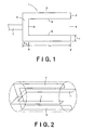
- Figs. 1 and 3 to 6 are sectional views of preferred embodiments of the sintered electrode for a cold cathode tube according to the present invention. Each of these drawings shows a section parallel to the longitudinal axis direction of the sintered electrode for a cold cathode tube.
- the sintered electrode (1) for a cold cathode tube according to the present invention shown in Fig. 1 comprises a cylindrical side wall part (2), a bottom part (3) provided at one end of the side wall part (2), and an opening (4) at another end of the side wall part (2), wherein the surface roughness (Sm) of the inner surface (5) of the electrode is not more than 100 ⁇ m.
- the term "side wall part” as used herein refers to the sintered electrode (1) for a cold cathode tube in its part present on an edge end face (4') side from the deepest part [that is, a part where the distance (L1) between the edge end face (4') in the opening (4) and the inner wall surface of the electrode is the longest] (6).
- bottom refers to the sintered electrode (1) for a cold cathode tube in its part which is present on the opposite side of the edge end face (4') from the deepest part (6).
- the inner surface (5) refers to both the inner surface of the cylindrical side wall part (2) and the inner surface of the bottom (3) in the sintered electrode (1) for a cold cathode tube.
- one of main features is that the surface roughness of the inner surface (5) is in a predetermined Sm range.
- each area in the inner surface (5) is not always required to have an identical Sm value.
- so far as substantially the whole area (preferably not less than 30%, particularly preferably not less than 50% of the area of the inner surface (5)) of the inner surface (5) falls within the predetermined Sm range the whole area of the inner surface (5) is not always required in a predetermined Sm range. Accordingly, in some cases, the area of a part of the inner surface (5) is not required to fall within the predetermined Sm range.
- the outer surface of the sintered electrode (1) for a cold cathode tube that is, including, for example, the outer surface of the cylindrical side wall part (2) and the outer surface of the bottom (3) and the surface of the edge end face (4')]
- Sm on the outer surface of the sintered electrode (1) for a cold cathode tube is any desired value and may be the same as or different from the above Sm range specified on the inner surface of the sintered electrode (1) for a cold cathode tube.
- the term "thickness" of the bottom as used herein refers to the distance (L2) in the bottom between the above deepest part (6) and the outer surface of the bottom of the sintered electrode for a cold cathode tube.
- the term “thickness” of the side wall part refers to the distance (L3) in the side wall part between the inner surface and the outer surface of the sintered electrode for a cold cathode tube.
- the term “average thickness” refers to an average thickness value (unit: “mm") obtained by measuring the maximum thickness (L MAX ) and the minimum thickness (L MIN ) for each of four side wall sections [(i) to (iv)] obtained from a first section passed through the center of a cylindrical sintered electrode for a cold cathode tube [hereinafter referred to as "first section”; two side wall sections, i.e., a side wall section (i) and a side wall section (ii) in pair with the side wall section (i), are obtained from the first section] and a second section passed through the center of the cylindrical sintered electrode for a cold cathode tube and orthogonal to the first section [hereinafter referred to as "second section”; a side wall section (iii) and a side wall section (iv) in pair with the side wall section (iii) are obtained from the second section], and calculating an average thickness based on the measured
- the term "average thickness” as used herein refers to an average thickness value obtained by measuring the maximum thickness (L MAX ) and the minimum thickness (L MIN ) for each bottom of four sections obtained from the first section and the second section in the same manner as described above, and calculating the average value based on the measured data according to the above equation.
- a wire rod or/and a foil material formed of any one of molybdenum (Mo), W (tungsten), and KOV (kovar alloy) is joined to substantially the center part of the bottom (3) in the sintered electrode (1) for a cold cathode tube.
- a dumet wire or a nickel (Ni) wire (7) is further joined to the wired rod or foil material. Voltage is applied to the sintered electrode (1) for a cold cathode tube through the dumet wire (7).
- a protrusion part (8) may be provided at a joint between the sintered electrode (1) for a cold cathode tube and the Mo, W or KOV wire dumet wire (7).
- the distance (L4) between the inner surface of the bottom (3) in the sintered electrode (1) for a cold cathode tube and the joint to the Mo, W or KOV wire dumet wire (7) is regarded as the thickness of the bottom.
- the thickness of the bottom is increased by this protrusion part (8) and, as a result, the service life and durability of the electrode for a cold cathode tube can be improved.
- the surface roughness (Sm) of the inner surface is not more than 100 ⁇ m.
- the reason for this is that, in a closed-end electrode, in order to lower the operating voltage, in particular, a larger electrode surface area is more advantageous, and, in particular, since discharge occurs around the inner side of the electrode, increasing the inner side surface area of the electrode is preferred.
- the Sm value exceeds 100 ⁇ m, the advantageous effect on the operating voltage is poor.
- the mercury consumption is also likely to be significantly increased, making it difficult to attain the object of the present invention, that is, to provide a long-service life cold cathode tube which has low operating voltage and significantly suppressed mercury consumption.
- the Sm range is not less than 40 ⁇ m, preferably not more than 90 ⁇ m, particularly preferably not more than 50 ⁇ m.
- the surface roughness (Sm) of the inner surface can be provided by setting sinter production conditions (for example, particle diameter of raw material powder) so as to provide a sintered electrode having the above inner surface, or by providing a sinter and subjecting the sinter to suitable processing (for example, polishing such as barreling or blasting, or etching) after the preparation of sinter.
- sinter production conditions for example, particle diameter of raw material powder
- suitable processing for example, polishing such as barreling or blasting, or etching
- the average thickness of the side face part is preferably not less than 0.1 mm and not more than 0.7 mm. This is so because, in the operation as a cold cathode tube, when the average thickness is less than 0.1 mm, problems sometimes occurs such as unsatisfactory strength or hole formation. When the average thickness exceeds 0.7 mm, the surface area on the inner side of the sintered electrode for a cold cathode tube is reduced and, consequently, the effect of reducing the operating voltage cannot be satisfactorily attained.
- the average thickness of the side face part is preferably not less than 0.3 mm and not more than 0.6 mm, particularly preferably not less than 0.35 mm and not more than 0.55 mm.
- the average thickness of the bottom face part is preferably not less than 0.25 mm and not more than 1.5 mm.
- the reason for this is as follows. Since the inner side of the bottom face part of the electrode is significantly consumed, the thickness is preferably more than 0.25 mm. When the thickness exceeds 1.5 mm, the surface area of the inner side is reduced. In this case, as with the above case, the effect of reducing the operating voltage cannot be satisfactorily attained.
- the average thickness of the bottom face part is preferably not less than 0.4 mm and not more than 1.35 mm, particularly preferably not less than 0.6 mm and not more than 1.15 mm.
- the sintered electrode for a cold cathode tube according to the present invention may be formed of any purposive high-melting metal.
- the sintered electrode for a cold cathode tube may be formed of a simple substance of a metal preferably selected from tungsten (W), niobium (Nb), thallium (Ta), titanium (Ti), molybdenum (Mo), and rhenium (Re), or at least one alloy of the above metals.
- Mo is a preferred metal.
- rare earth elements such as lanthanum (La), cerium (Ce), and yttrium (Y), rare earth carboxides (particularly preferably "rare earth element (R)-carbon (C)-oxygen (O) compounds" (details thereof will be described later), and Mo to which oxides of light elements such as barium (Ba), magnesium (Mg), and calcium (Ca) have been added.
- preferred alloys include W-Mo alloys, Re-W alloys, and Ta-Mo alloys. Further, if necessary, a mixture of an electron emission substance with a high-melting metal may be used.
- Ni nickel
- Cu copper
- Fe iron
- P phosphorus
- a very small amount for example, not more than 1% by mass
- the Mo-based or W-based metal which is less likely to be nitrided, is preferred.
- the Mo-based metal which can be sintered at a low temperature is more preferred than the W-based metal.
- the average diameter of crystal grains of the sinter is preferably not more than 100 ⁇ m.
- the aspect ratio (major axis/minor axis) of the crystal grains of the sinter is preferably not more than 5.
- the relative density is preferably not less than 80%, particularly preferably not less than 90% and not more than 98%.
- the relative density is measured by the following method.
- the length of the sintered electrode for a cold cathode tube according to the present invention is mainly determined depending, for example, upon the size and performance of the cold cathode tube in which the electrode is incorporated.
- the electrode length is not less than 3 mm and not more than 8 mm, particularly preferably not less than 4 mm and not more than 7 mm.
- the diameter of the sintered electrode for a cold cathode tube is determined depending, for example, upon the size and performance of the cold cathode tube in which the electrode is incorporated. Preferably, however, the diameter is not less than 1.0 mm ⁇ and not more than 3.0 mm ⁇ , particularly preferably not less than 1.3 mm ⁇ and not more than 2.7 mm ⁇ .
- the sintered electrode according to the present invention is useful in such small electrodes.
- the ratio between the length and the diameter of the sintered electrode for a cold cathode tube is preferably not less than 2 and not more than 3, particularly preferably not less than 2.2 and not more than 2.8.
- the shape of the cylindrical space in a section parallel to the longitudinal axis direction is preferably rectangular as shown in Fig. 1 or trapezoidal as shown in Fig. 3 , for example, from the viewpoints of large surface area, easy production and processing, and workability of mounting on a hollow bulb in the production of the cold cathode tube.
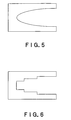
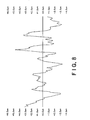
- the shape of the cylindrical space is not limited to the above shape, and various shapes such as shown in Fig. 4 (V-shape in section), Fig. 5 (U-shape in section), and Fig. 6 (stair form in section) may be adopted.
- the outer shape of the side wall part is preferably cylindrical. However, the outer shape may be other one (for example, elliptical or polygonal).
- the outer shape of the sintered electrode for a cold cathode tube may be different from the inner shape of the sintered electrode for a cold cathode tube.
- the above construction can provide a long-service life cold cathode tube which has low operating voltage and significantly suppressed mercury consumption.
- the sintered electrode for a cold cathode tube according to the present invention may be produced by mixing raw material powders, granulating the mixture, molding the granules into a desired shape, and then sintering the molded product.
- a preferred production process of a sintered electrode for a cold cathode tube according to the present invention will be described by taking molybdenum as a representative example.
- the molybdenum powder as the raw material powder has an average particle diameter of not less than 1 ⁇ m and not more than 5 ⁇ m and a purity of not less than 99.95%.
- This powder is mixed with pure water, a binder (preferably polyvinyl alcohol (PVA)), and the mixture is granulated.
- a cup-shaped molded product for example, 3.0 mm in diameter x 7.0 mm in length, average thickness of side face part 0.5 mm, average thickness of bottom face part 1.0 mm, bottom face protrusion R 0.6 mm (this protrusion part is not included in the length 7.0 mm)] is produced by a single action press, a rotary press, or injection molding.
- the protrusion part may if necessary be in a lead form.
- degreasing is carried out in a dry hydrogen atmosphere of 800°C to 1000°C.
- the degreasing time is preferably 4 hr or less. When the degreasing time exceeds 4 hr, the content of carbon in the rare earth carboxide is disadvantageously lowered.
- Sintering is then carried out in a hydrogen atmosphere under conditions of 1700 to 1800°C x 4 hr or longer and further is if necessary subjected to hot isostatic pressing (HIP) under conditions of 1100 to 1600°C x 100 to 250 MPa.
- HIP hot isostatic pressing
- the surface roughness (Sm) of the inner side of the closed-end shape part may be regulated.
- An example of a surface roughness regulation method is barrel polishing or blasting. In this case, for example, the abrasive material used and work content may be properly selected or regulated.
- the sintered electrode for a cold cathode tube is formed of a sinter of a high-melting metal containing a rare earth element (R)-carbon (C)-oxygen (O) compound.
- the "rare earth element (R)-carbon (C)-oxygen (O) compound” refers to a compound containing a rare earth element (R), carbon (C), and oxygen (O) as constituents.
- Rare earth elements include, for example, lanthanum (La), cerium (Ce), samarium (Sm), praseodymium (Pr), and neodymium (Nd). Among them, lanthanum (La), cerium (Ce), and samarium (Sm) are particularly preferred.
- rare earth element (R)-carbon (C)-oxygen (O) compound may contain a plurality of rare earth elements in an identical compound.
- the sinter of the sintered electrode for a cold cathode tube may contain a plurality of types of "rare earth element (R)-carbon (C)-oxygen (O) compounds" which are different from each other in type of rare earth element, its content, or carbon and/or oxygen content.
- the composition of the sinter constituting the sintered electrode for a cold cathode tube can easily be judged by color mapping using EPMA (electron probe micro analyzer). Accordingly, in the sintered electrode for a cold cathode tube according to the present invention, the presence of the above "rare earth element (R)-carbon (C)-oxygen (O) compound" in the sinter is observed as at least one of the sinter constituents other than the high-melting metal, as judged by color mapping using EPMA.
- EPMA electron probe micro analyzer
- This "rare earth element (R)-carbon (C)-oxygen (O) compound” may be represented by chemical formula R x C y O z or R x O y (CO z ) a wherein R represents a rare earth element; x, y, z, and a are any number.
- Possible such compounds include, for example, (i) La-based compounds such as LaCO, La 2 O(CO 3 ) 2 , La 2 O 2 CO 3 , La 2 CO 5 , La 2 O(CO 3 ) 2 , and La 2 O 2 CO 3 , (ii) Ce-based compounds such as CeO 2 C 2 and Ce 4 O 2 C 2 , (iii) Sm-based compounds, for example, SmO 0.5 C 0.4 and Sm 2 CO 5 Sm 2 O 2 CO 3 , (iv) compounds having an indefinite structure, (5) mixtures or compounds comprising the above compounds (1) to (4), and (6) other compounds.
- La-based compounds such as LaCO, La 2 O(CO 3 ) 2 , La 2 O 2 CO 3 , La 2 CO 5 , La 2 O(CO 3 ) 2 , and La 2 O 2 CO 3
- Ce-based compounds such as CeO 2 C 2 and Ce 4 O 2 C 2
- Sm-based compounds for example, SmO 0.5 C 0.4 and Sm
- the content of the rare earth element (R)-carbon (C)-oxygen (O) compound is preferably more than 0.05% by mass and not more than 20% by mass in terms of the rare earth element (R), particularly preferably more than 0.5% by mass and not more than 10% by mass.
- the cathode voltage drop is disadvantageously high, while, when the content is more than 10% by mass, sintering is disadvantageously less likely to proceed. For the above reason, both the above content ranges are unfavorable.
- the content of carbon in the sinter constituting the sintered electrode for a cold cathode tube according to the present invention is preferably more than 1 ppm and not more than 100 ppm, particularly preferably more than 5 ppm and not more than 70 ppm.
- the carbon content is not more than 1 ppm, the cathode voltage drop is high, while, a carbon content exceeding 100 ppm is disadvantageous in that, when the sinter is used as the electrode, gas (mainly CO 2 gas) release has an adverse effect on discharge.
- the carbon content is preferably in the above-defined range.
- the carbon content can be determined by measuring infrared absorption properties of a sample in a state free from carbon contamination from environment (for example, preferably within a clean room). The amount of the sample should be not less than 5 g to enhance detection accuracy.
- the content of oxygen in the sinter constituting the sintered electrode for a cold cathode tube according to the present invention is preferably more than 0.01 % by mass and not more than 6% by mass, particularly preferably more than 0.1 % by mass and not more than 3% by mass.
- the oxygen content is not more than 0.01 % by mass, disadvantageously, the rare earth metal is likely to evaporate during use.
- an oxygen content of more than 3.0% by mass is disadvantageous in that, when the sinter is used as the electrode, gas (mainly CO 2 gas) release has an adverse effect on discharge.
- the oxygen content is preferably in the above-defined range.
- the rare earth element (R)-carbon (C)-oxygen (O) compound is preferably present, in the sinter, as particles having an average particle diameter of not more than 10 ⁇ m, particularly preferably not more than 5 ⁇ m.
- the average particle diameter is more than 10 ⁇ m, the diffusion of the above compound on the electrode surface is unsatisfactory and, further, the distribution quantity of the above compound on the electrode surface is reduced, resulting in increased cathode voltage drop. For this reason, the above-defined particle diameter range is preferred.
- the term "average particle diameter" is determined by conducting measurement in three or more places of 40 ⁇ m x 40 ⁇ m under an electron microscope and determining the average value of the maximum diameters of the projected particles.
- the sintered electrode for a cold cathode tube according to the present invention formed of the above sinter, the recrystallization of the sintered structure upon the application of a high voltage current has been suppressed. Accordingly, in the present invention using the specific sinter, higher-voltage welding conditions can be adopted in welding a lead wire to the electrode. Therefore, in a conventional electrode produced by conventional drawing, high-voltage welding conditions, which could not have been substantially adopted in the conventional electrode produced by conventional drawing, can be adopted in the present invention, and, thus, a sintered electrode for a cold cathode tube having a higher lead wire weld strength than the conventional cold cathode tube can easily be prepared.
- a sintered electrode for a cold cathode tube which can provide a long-service life cold cathode tube having low operating voltage and significantly suppressed mercury consumption and, at the same time, can realize a lead wire weld strength of not less than 400 N/mm 2 per unit sectional area, can easily be provided.
- the weld strength per unit sectional area of the lead wire may be measured as follows.
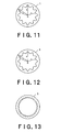
- a sintered electrode 1 for a cold cathode tube having a lead wire welded to its bottom is fixed within a slit formed in a chucking A.
- a lead wire 9 is fixed with a chucking B, and the chucking A is pulled at a rate of 10 mm/min.
- the inner wall surface of the cylindrical side wall part is in a concave-convex form.
- the inner surface area of the electrode that is, surface area within the tube in a tubular electrode
- the utilization of a hollow cathode effect derived from the tubular shape of the electrode can be maximized.
- the sintered electrode for a cold cathode tube according to the present invention can further lower the operating voltage of the cold cathode tube.
- the concave-convex shape on the inner wall surface of the cylindrical side wall part may be any one.
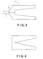
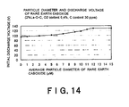
- Specific examples of preferred concave-convex shapes include, for example, a corrugated shape as shown in Fig. 11 and concave-convex shapes as shown in Figs. 12 and 13 .
- the corrugated shape shown in Fig. 11 has large surface area and hollow cathode effect and is particularly excellent in easiness on production and processing and durability or the like.
- the form of the inner wall surface of the cylindrical side wall part is such that the ratio b/a, wherein a represents the outer diameter distance from an imaginary center O calculated from the outer diameter of the sintered electrode for a cold cathode tube and b represents the inner diameter maximum length, is more than 0.50 and not more than 0.95, and the ratio c/b, wherein c represents the inner diameter minimum length and b is as defined above, is more than 0.50 and not more than 0.95.
- the imaginary center (O) is a value determined with a roundness measuring device by "minimum area method" specified in JIS B 7451.
- the "outer diameter distance a" refers to an average distance between the imaginary center (O) and a plurality of points (preferably 8 points or more) present on the outer surface of the cylindrical side wall part in a section (the same section) perpendicular to the longitudinal axis direction of the sintered electrode for a cold cathode tube.
- the “inner diameter maximum length b” refers to a distance between the above imaginary center (O) and the farthermost point present on the inner surface of the side wall part in the same section.
- the “inner diameter minimum length c” refers to a distance between the imaginary center (O) and the nearmost point present on the inner surface of the side wall part in the same section.
- the ratio between the inner diameter maximum length b and the outer diameter distance a i.e., b/a
- the mold used in the production of the electrode is likely to be broken.
- the b/a ratio exceeds 0.95, in the production of the electrode, cracking is likely to occur in the electrode and, consequently, the reject rate is enhanced.
- the ratio between the inner diameter maximum length b and the outer diameter distance a i.e., c/b
- the c/b ratio exceeds 0.95, the effect of improving the surface area of the internal wall surface is reduced.
- the b/a range and the c/b range are preferably in the above-defined respective ranges.
- the concave-convex shape of the inner wall surface of the electrode is such that identical or similar concaves and/or convexes are regularly arranged, or concaves and convexes which are quite different from each other in size and shape are irregularly present. Further, in the whole section of a part extending from the opening to bottom in the cylindrical electrode, concaves and convexes having a substantially identical shape are provided on the inner wall part, or alternatively concaves and convexes may be changed in a some portion between the opening and the bottom, or further alternatively concave-convex shape-free parts may be present. In this case, the inner diameter maximum length b and the inner diameter minimum length c, b/a, and c/b, vary depending upon the cylindrical electrode part (that is, sectional position).
- the concave-convex shape of the inner wall surface in the electrode is preferably such that work for taking out the resultant sinter from the mold is easy and, further, the strength is even over the whole area without a local lack of strength. Accordingly, the concave-convex shape of the inner wall surface of the electrode is particularly preferably such that, in a section perpendicular to the longitudinal axis direction of the electrode, the concave and convex are relatively gently continued and, in a section parallel to the longitudinal axis direction of the electrode, the same concave-convex shape is continuously formed. An example of this is shown in Fig.
- the sintered electrode for a cold cathode tube in which the inner wall surface of the cylindrical side wall part has the above shape may be produced by any desired method.
- a method using a mold constructed so as to form a cylindrical sinter having the above inner wall surface shape is preferably adopted.
- after the production of the sinter for example, barrelling, washing, and annealing are carried out to fabricate the inner side of the cylindrical side wall part into the above shape.
- the sintered electrode for a cold cathode tube according to the present invention in which the inner wall surface has the above predetermined shape may be produced by mixing raw material powders together, granulating the mixture, molding the granules into a predetermined shape and then sintering the molded product.
- a preferred production process of the sintered electrode for a cold cathode tube according to the present invention will be described by mainly taking molybdenum as an example.
- the molybdenum powder as the raw material powder has an average particle diameter of not less than 1 ⁇ m and not more than 5 ⁇ m, a purity of not less than 99.95%, and an oxygen content of not more than 0.5% by mass.
- the rare earth metal usually oxide
- the rare earth metal has an average particle diameter of not less than 0.1 ⁇ m and not more than 2 ⁇ m.
- Pure water and a binder are mixed in the powder, followed by granulation.
- a molded product is produced from the granules by a single press, a rotary press, or injection molding using a mold suitable for the formation of an inner wall surface having a predetermined shape.
- degreasing treatment is carried out in dry hydrogen at a temperature of 800°C or above and 1000°C or below for 4 hr or less. In this case, when degreasing is carried out for more than 4 hr, the carbon content is sometimes excessively lowered.
- sintering is carried out in hydrogen at a temperature of 1700°C or above and 1800°C or below for not less than 4 hr. If necessary, barreling, washing and annealing are carried out to prepare a sinter (for example, 1 to 3 mm in diameter x 3 to 6 mm in length) having predetermined concaves and convexes in its inner wall surface.
- a molybdenum rod having a diameter of 0.8 mm and a length of 2.6 mm is welded to a dumet rod having a diameter of 0.6 mm and a length of 40 mm to complete the assembly of the electrode.
- a kovar alloy and nickel may be used as an insert metal for the electrode and the molybdenum rod.
- the cold cathode tube according to the present invention is characterized by comprising: a hollow tubular light transparent bulb into which a discharge medium has been sealed; a fluorescent material layer provided on the inner wall surface of the tubular light transparent bulb; and a pair of the above sintered electrodes for a cold cathode tube provided respectively on both ends of the tubular light transparent bulb.
- a discharge medium, a tubular light transparent bulb, and a fluorescent material layer which are indispensable constituent elements other than the sintered electrode for a cold cathode tube
- those which have hitherto been used in this type of cold cathode tubes, particularly cold cathode tubes for backlight in liquid crystal displays, may be used either as such or after suitable alteration.
- examples of discharge media include rare gas-mercury systems (examples of rare gases including argon, neon, xenon, krypton, and mixtures thereof), and examples of fluorescent materials include fluorescent materials which emit light upon ultraviolet light stimulation, preferably calcium halophosphate fluorescent materials.
- hollow tubular light transparent bulbs include glass tubes having a length of not less than 60 mm and not more than 700 mm and a diameter of not less than 1.6 mm and not more than 4.8 mm.
- the liquid crystal display device is characterized by comprising: the above sintered electrode for a cold cathode tube; a light guide body disposed closely to the sintered electrode for a cold cathode tube; a reflector disposed on one surface side of the light guide body; and a liquid crystal display panel disposed on another surface side of the light guide body.
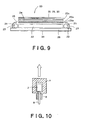
- FIG. 9 is a cross-sectional view of a particularly preferred embodiment of the liquid crystal display device according to the present invention.
- a liquid crystal display device 20 shown in Fig. 9 comprises a cold cathode tube 21, a light guide body 22 disposed closely to the cold cathode tube 21, a reflector 23 disposed on one surface side of the light guide body 22; and a liquid crystal display panel 24 disposed on another surface side of the light guide body 22. Further, a light diffuser 25 is disposed between the light guide body 22 and the liquid crystal display panel 24.
- a reflector 27 for a cold cathode tube which reflects light from the cold cathode tube 21 toward the light guide body 22 side is provided.
- the number of cold cathode tubes may be any desired one.
- two (total) cold cathode tubes 21 may be disposed closely to two opposed sides of the light guide body 22.
- One or at least two cold cathode tubes may be disposed closely to one side (or three or more sides) of the light guide body.
- the number and shape of the light diffuser 25 may also be any desired ones.
- At least one sheet light diffuser 25a to which light diffusing properties have been imparted by allowing light diffusing particles to exist within the diffuser, and at least one lens or prism light diffuser 25b to which light diffusing properties have been imparted by regulating the surface shape may be disposed between the light guide body 22 and the liquid crystal display panel 24.
- a light diffuser 25c, a surface protector 28, an antireflector 29 for preventing or reducing external light reflection or external light catching, and an antistatic body 30 may be provided on the viewer side of the liquid crystal display panel 24.
- Two or more of these light diffusers 25a, 25b, 25c, surface protector 28, antireflector 29, antistatic body 30 and the like may be composited to provide one or at least two layers which simultaneously have a plurality of functions.
- the light diffusers 25a, 25b, 25c, and the surface protector 28, antireflector 29, and antistatic body 30 may not be provided when desired functions as the liquid crystal display device can be exhibited without these constituent elements.
- a support substrate 26, a frame, and a spacer for holding individual constituent members of the liquid crystal display device 20 that is, the cold cathode tube 21, the light guide body 22, the reflector 23, the liquid crystal display panel 24, the light diffusers 25a, 25b, 25c, the surface protector 28, the antireflector 29, and the antistatic body 30 and the like
- individual constituent members of the liquid crystal display device 20 that is, the cold cathode tube 21, the light guide body 22, the reflector 23, the liquid crystal display panel 24, the light diffusers 25a, 25b, 25c, the surface protector 28, the antireflector 29, and the antistatic body 30 and the like
- a heat radiating member 31 and the like may also be provided.
- liquid crystal display device as with the conventional liquid crystal display device, for example, electric wiring and LSI chip for supplying drive voltage to the liquid crystal display panel 24, electric wiring for supplying drive voltage to the cold cathode tube 21, and a seal material for preventing leakage of light toward unnecessary parts and the entry of dust or moisture into the device may be provided at the respective necessary sites.
- the cold cathode tube 21 should satisfy predetermined requirements which have been described above in detail.
- various constituent members for example, the light guide body 22, the light reflector 23, the liquid crystal display panel 24, the light diffuser 25a, 25b, 25c, the support substrate 26, the reflector 27 for a cold cathode tube, the surface protector 28, the antireflector 29, the antistatic body 30, the heat radiating member 31, the frame, the case, and the seal member
- Electrodes were prepared under varied conditions as shown in Tables 1 to 4 and were incorporated in a cold cathode tube for the evaluation of properties.
- the cold cathode tube had an outer diameter of 3.2 mm and an interelectrode distance of 350 mm, and a mixed gas composed of mercury and neon/argon was sealed into the tube.
- the results of measurement of the operating voltage are shown in Tables 1 to 4.
- Example 10 Nb 70 0.45 0.85 95 None 555 0.34
- Example 11 Nb 90 0.45 0.85 95 None 563 0.36
- Example 12 Nb 100 0.45 0.85 95 None 570 0.40 Comparative Example 13 Nb 110 0.45 0.85 95 None 574 0.47 Comparative Example 14 Nb 120 0.45 0.85 95 None 574 0.47 Comparative Example 15 Nb 130 0.45 0.85 95 None 575 048
- Example 15 Ta 90 0.45 0.85 95 None 563 0.36
- Example 21 W 40 0.45 0.85 95 None 545 0.30
- Example 22 W 70 0.45 0.85 95 None 555 0.34
- Example 23 W 90 0.45 0.85 95 None 563 0.36
- Example 25 10%Re-Mo 40 0.45 0.85 95 None 545 0.30
- Example 26 10%Re-Mo 70 0.45 0.85 95 None 555 0.34
- Example 27 10%Re-Mo 90 0.45 0.85 95 None 563 0.36
- Example 28 10%Re-
- Electrodes were prepared under varied conditions as shown in Tables 5 to 7 and were incorporated in a cold cathode tube for the evaluation of properties.
- the shape was as shown in Fig. 1 , and the surface roughness (Sm) of the inner surface of the electrode was not more than 100 ⁇ m.
- the cold cathode tubes had an outer diameter of 2.0 mm and an interelectrode distance of 350 mm, and a mixed gas composed of mercury and neon/argon was sealed into the tube.
- "rare gas discharge mode" in which mercury within the tube is consumed as a result of the formation of an amalgam with the sputtering material is dominative. Therefore, the service life can be evaluated by evaluating the amount of mercury consumed.
- the results of measurement of the amount of mercury consumed after 10000 hr are also shown in Tables 5 to 7.
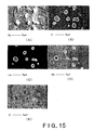
- Fig. 15(A) represents a reflection electron image (SEM image), (B) an oxygen (O) color mapped image, (C) a lanthanum (La) color mapped image, (D) a molybdenum (Mo) color mapped image, and (E) a carbon (C) color mapped image.
- SEM image reflection electron image
- O oxygen
- C a lanthanum
- Mo molybdenum
- E a carbon
- Sintered electrodes for a cold cathode tube which comprise an Mo sinter containing the composition of Example 59 (2% La-O-C compound (O 2 content 0.4% by mass, C content 50 ppm) and has a corrugated shape as shown in Fig. 11 on the inner wall of the cylindrical side wall part, were prepared to provide a plurality of sintered electrodes for a cold cathode tube as shown in Table 8 (for all the electrodes, the outer diameter distance a is 0.085 mm).
- Each electrode was incorporated in a cold cathode tube in the same manner as in Example 59, and the properties thereof were evaluated in the same manner as in Example 59.
- Example 60 and Comparative Example 34 the weld strength was measured.
- the electrode was welded to an Mo lead of 0.8 mm in diameter x 2.6 mm through a kovar foil of 1.0 mm in diameter x 0.1 mm in length, and welding was carried out using a direct current of 500 A x 30 ms.
- 10 assemblies were prepared. These assemblies were subjected to a tensile test at a speed of 10 mm/min ( Fig. 10 ), and the weld strength values were compared. The results are shown in Table 9.
- Example 144 (Example 60) 1 292 429 2 312 501 3 273 532 4 331 541 5 370 519 6 361 485 7 331 500 8 351 439 9 380 551 10 370 472 Average 337 497
- the sintered electrode in the example of the present invention has a high strength of joining to the lead wire.
Landscapes
- Discharge Lamp (AREA)
- Liquid Crystal (AREA)
- Planar Illumination Modules (AREA)
Claims (15)
- Gesinterte Elektrode (1) für eine Kaltkathodenröhre, die ein zylinderförmiges Seitenwandteil (2), ein Unterteil (3), das sich an dem einen Ende des Seitenwandteils (2) befindet, und eine Öffnung (4), die sich an dem anderen Ende des Seitenwandteils (2) befindet, umfasst, dadurch gekennzeichnet, dass die Oberflächenrauheit (Sm) der inneren Oberfläche (5) der Elektrode (1) nicht weniger als 40 µm und nicht mehr als 100 µm beträgt.
- Gesinterte Elektrode für eine Kaltkathodenröhre gemäß Anspruch 1, wobei das Seitenwandteil eine durchschnittliche Dicke von nicht weniger als 0,1 mm und nicht mehr als 0,7 mm hat.
- Gesinterte Elektrode für eine Kaltkathodenröhre gemäß Anspruch 1 oder 2, wobei das Unterteil eine durchschnittliche Dicke von nicht weniger als 0,25 mm und nicht mehr als 1,5 mm hat.
- Gesinterte Elektrode für eine Kaltkathodenröhre gemäß einem der Ansprüche 1 bis 3, die aus einem Metall, ausgewählt aus Wolfram (W), Niob (Nb), Thallium (Ta), Titan (Ti), Molybdän (Mo) und Rhenium (Re) oder einer Legierung davon, gebildet wird.
- Gesinterte Elektrode für eine Kaltkathodenröhre gemäß einem der Ansprüche 1 bis 4, die eine relative Dichte von nicht weniger als 80 % hat.
- Gesinterte Elektrode für eine Kaltkathodenröhre gemäß einem der Ansprüche 1 bis 5, die ein Sintergut eines hochschmelzenden Metalls, das eine Seltenerdelement (R)-Kohlenstoff (C)-Sauerstoff (O)-Verbindung enthält, umfasst.
- Gesinterte Elektrode für eine Kaltkathodenröhre gemäß Anspruch 6, wobei der Gehalt der Seltenerdelement (R)-Kohlenstoff (C)-Sauerstoff (O)-Verbindung mehr als 0,05 Massen% und nicht mehr als 20 Massen%, bezogen auf das Seltenerdelement (R), beträgt.
- Gesinterte Elektrode für eine Kaltkathodenröhre gemäß Anspruch 6 oder 7, wobei der Gehalt an Kohlenstoff mehr als 1 ppm und nicht mehr als 100 ppm beträgt.
- Gesinterte Elektrode für eine Kaltkathodenröhre gemäß einem der Ansprüche 6 bis 8, wobei der Gehalt an Sauerstoff mehr als 0,01 Massen% und nicht mehr als 6 Massen% beträgt.
- Gesinterte Elektrode für eine Kaltkathodenröhre gemäß einem der Ansprüche 6 bis 9, wobei die Seltenerdelement (R)-Kohlenstoff (C)-Sauerstoff (O)-Verbindung als Partikel mit einem durchschnittlichen Partikeldurchmesser von nicht mehr als 10 µm in dem Sintergut vorliegt.
- Gesinterte Elektrode für eine Kaltkathodenröhre gemäß einem der Ansprüche 1 bis 10, wobei in einem Bereich senkrecht zu der Längsachsenrichtung der gesinterten Elektrode für eine Kaltkathodenröhre die innere Wandoberfläche des zylinderförmigen Seitenwandteils in einer konkav-konvexen Form vorliegt.
- Gesinterte Elektrode für eine Kaltkathodenröhre gemäß Anspruch 11, wobei in einem Bereich senkrecht zu der Längsachsenrichtung der gesinterten Elektrode für eine Kaltkathodenröhre die Form der inneren Wandoberfläche des zylinderförmigen Seitenwandteils so ist, dass das Verhältnis b/a, wobei a die äußere Durchmesserentfernung von einem imaginären Zentrum O, berechnet von dem äußeren Durchmesser der gesinterten Elektrode für eine Kaltkathodenröhre, darstellt und b die maximale innere Durchmesserlänge darstellt, mehr als 0,50 und nicht mehr als 0,95 beträgt und das Verhältnis c/b, wobei c die minimale innere Durchmesserlänge darstellt und b wie oben definiert ist, mehr als 0,50 und nicht mehr als 0,95 beträgt.
- Gesinterte Elektrode für eine Kaltkathodenröhre, die einen Zuleitungsdraht, der an das Unterteil der gesinterten Elektrode für eine Kaltkathodenröhre gemäß einem der Ansprüche 1 bis 12 geschweißt ist, umfasst, wobei die Schweißstärke pro Querschnittseinheit des Zuleitungsdrahts nicht weniger als 400 N/mm2 beträgt.
- Kaltkathodenröhre, dadurch gekennzeichnet, dass sie umfasst :einen hohlen röhrenförmigen lichtdurchlässigen Kolben, in dem ein Entladungsmedium eingeschlossen worden ist;eine fluoreszierende Materialschicht, die auf der inneren Wandoberfläche des röhrenförmigen lichtdurchlässigen Kolbens bereitgestellt ist; undein gesintertes Elektrodenpaar für eine Kaltkathodenröhre gemäß einem der Ansprüche 1 bis 13, das entsprechend an beiden Enden des röhrenförmigen lichtdurchlässigen Kolbens bereitgestellt ist.
- Flüssigkeitskristallanzeigenvorrichtung, dadurch gekennzeichnet, dass sie umfasst:eine Kaltkathodenröhre gemäß Anspruch 14;einen Lichtleitkörper, der nahe an der Kaltkathodenröhre angeordnet ist;einen Reflektor, der an einer Oberflächenseite des Lichtleitkörpers angebracht ist; undein Flüssigkeitskristall-Anzeigenpaneel, das an der anderen Oberfläche des Lichtleitkörpers angebracht ist.
Applications Claiming Priority (2)
| Application Number | Priority Date | Filing Date | Title |
|---|---|---|---|
| JP2004139559 | 2004-05-10 | ||
| PCT/JP2005/008306 WO2005109469A1 (ja) | 2004-05-10 | 2005-05-02 | 冷陰極管用焼結電極、この冷陰極管用焼結電極を具備する冷陰極管および液晶表示装置 |
Publications (3)
| Publication Number | Publication Date |
|---|---|
| EP1746632A1 EP1746632A1 (de) | 2007-01-24 |
| EP1746632A4 EP1746632A4 (de) | 2011-01-05 |
| EP1746632B1 true EP1746632B1 (de) | 2012-08-15 |
Family
ID=35320462
Family Applications (1)
| Application Number | Title | Priority Date | Filing Date |
|---|---|---|---|
| EP05737302A Active EP1746632B1 (de) | 2004-05-10 | 2005-05-02 | Gesinterte elektrode zur verwendung in kaltkathodenröhren, mit dieser gesinterten elektrode zur verwendung in kaltkathodenröhren ausgestattete kaltkathodenröhre und flüssigkristall-display-einheit |
Country Status (7)
| Country | Link |
|---|---|
| US (1) | US7551242B2 (de) |
| EP (1) | EP1746632B1 (de) |
| JP (1) | JP4966008B2 (de) |
| KR (1) | KR100814530B1 (de) |
| CN (1) | CN100562969C (de) |
| TW (1) | TW200606524A (de) |
| WO (1) | WO2005109469A1 (de) |
Families Citing this family (13)
| Publication number | Priority date | Publication date | Assignee | Title |
|---|---|---|---|---|
| JP4614908B2 (ja) * | 2005-05-11 | 2011-01-19 | 日立粉末冶金株式会社 | 冷陰極蛍光ランプ用電極 |
| US8698384B2 (en) | 2006-03-16 | 2014-04-15 | Kabushiki Kaisha Toshiba | Sintered electrode for cold cathode tube, and cold cathode tube and liquid crystal display device using the sintered electrode |
| JP4832931B2 (ja) * | 2006-03-16 | 2011-12-07 | 株式会社東芝 | 冷陰極管用焼結電極の製造方法 |
| US8072560B2 (en) * | 2006-09-08 | 2011-12-06 | Kabushiki Kaisha Toshiba | Electrode for cold cathode tube, and cold cathode tube and liquid crystal display device using the same |
| KR101043849B1 (ko) * | 2006-10-13 | 2011-06-22 | 도시바 마테리알 가부시키가이샤 | 냉음극관용 전극과 그것을 이용한 냉음극관 |
| US7756184B2 (en) * | 2007-02-27 | 2010-07-13 | Coherent, Inc. | Electrodes for generating a stable discharge in gas laser system |
| CN101796608B (zh) * | 2007-09-07 | 2012-09-05 | 夏普株式会社 | 荧光管、显示装置用照明装置、显示装置 |
| EP2197020A4 (de) * | 2007-09-14 | 2012-12-26 | Nat University Corp Tohoku Unversity | Kathodenkörper und fluoreszenzröhre damit |
| JP2009110801A (ja) * | 2007-10-30 | 2009-05-21 | Nec Lighting Ltd | 冷陰極蛍光ランプ |
| JP2009252382A (ja) * | 2008-04-01 | 2009-10-29 | Sumitomo Electric Ind Ltd | 電極材料、電極、及び冷陰極蛍光ランプ |
| US8268035B2 (en) | 2008-12-23 | 2012-09-18 | United Technologies Corporation | Process for producing refractory metal alloy powders |
| CN104091740A (zh) * | 2014-01-24 | 2014-10-08 | 朱惠冲 | 高强度稀土钼管冷阴极及其制备工艺 |
| JP6677875B2 (ja) * | 2015-03-23 | 2020-04-08 | 三菱マテリアル株式会社 | 多結晶タングステン及びタングステン合金焼結体並びにその製造方法 |
Family Cites Families (11)
| Publication number | Priority date | Publication date | Assignee | Title |
|---|---|---|---|---|
| JPS5826444A (ja) * | 1981-08-10 | 1983-02-16 | Iwasaki Electric Co Ltd | 高圧ナトリウムランプ |
| JP2848975B2 (ja) * | 1991-02-08 | 1999-01-20 | ウシオ電機株式会社 | 蛍光ランプ |
| JPH07226185A (ja) * | 1994-02-09 | 1995-08-22 | Toho Kinzoku Kk | 管球用タングステン棒 |
| TW430840B (en) * | 1995-03-24 | 2001-04-21 | Hitachi Ltd | Cathode ray tube having an improved cathode structure and a method of making the same |
| US5962977A (en) | 1996-12-20 | 1999-10-05 | Ushiodenki Kabushiki Kaisha | Low pressure discharge lamp having electrodes with a lithium-containing electrode emission material |
| KR100434977B1 (ko) * | 1999-02-12 | 2004-06-09 | 도판 인사츠 가부시키가이샤 | 플라즈마 디스플레이 패널, 그 제조방법 및 그 제조장치 |
| JP3293815B2 (ja) | 1999-12-20 | 2002-06-17 | ハリソン東芝ライティング株式会社 | 冷陰極低圧放電灯 |
| JP2001332212A (ja) * | 2000-03-16 | 2001-11-30 | Stanley Electric Co Ltd | 電子放出用電極及び冷陰極蛍光管 |
| CN1121053C (zh) * | 2000-05-27 | 2003-09-10 | 中山大学 | 冷阴极电子发射表面层结构及其制造方法 |
| JP2003187740A (ja) * | 2001-12-19 | 2003-07-04 | Harison Toshiba Lighting Corp | 冷陰極形電極、放電ランプおよび照明装置 |
| FR2840450A1 (fr) * | 2002-05-31 | 2003-12-05 | Thomson Licensing Sa | Corps cathodo-emissif pour cathode impregnee de tube electronique |
-
2005
- 2005-04-29 TW TW094113942A patent/TW200606524A/zh unknown
- 2005-05-02 CN CNB2005800009471A patent/CN100562969C/zh active Active
- 2005-05-02 KR KR1020067004583A patent/KR100814530B1/ko active IP Right Grant
- 2005-05-02 WO PCT/JP2005/008306 patent/WO2005109469A1/ja not_active Application Discontinuation
- 2005-05-02 US US10/570,495 patent/US7551242B2/en active Active
- 2005-05-02 EP EP05737302A patent/EP1746632B1/de active Active
- 2005-05-02 JP JP2006519528A patent/JP4966008B2/ja active Active
Also Published As
| Publication number | Publication date |
|---|---|
| EP1746632A4 (de) | 2011-01-05 |
| EP1746632A1 (de) | 2007-01-24 |
| JP4966008B2 (ja) | 2012-07-04 |
| CN1842888A (zh) | 2006-10-04 |
| US20080192176A1 (en) | 2008-08-14 |
| WO2005109469A1 (ja) | 2005-11-17 |
| TWI314661B (de) | 2009-09-11 |
| TW200606524A (en) | 2006-02-16 |
| KR100814530B1 (ko) | 2008-03-17 |
| US7551242B2 (en) | 2009-06-23 |
| KR20060069487A (ko) | 2006-06-21 |
| CN100562969C (zh) | 2009-11-25 |
| JPWO2005109469A1 (ja) | 2008-03-21 |
Similar Documents
| Publication | Publication Date | Title |
|---|---|---|
| EP1746632B1 (de) | Gesinterte elektrode zur verwendung in kaltkathodenröhren, mit dieser gesinterten elektrode zur verwendung in kaltkathodenröhren ausgestattete kaltkathodenröhre und flüssigkristall-display-einheit | |
| TW201007809A (en) | Fluorescent lamp | |
| EP2472560A1 (de) | Elektrode für eine entladungslampe, verfahren zur herstellung der elektrode für eine entladungslampe und entladungslampe | |
| WO2008044334A1 (fr) | Électrode pour tube à cathode froide et tube à cathode froide l'utilisant | |
| EP2105946A2 (de) | Hochdruck-Entladungslampe | |
| KR20090082342A (ko) | 수은방출체, 이를 이용한 저압 방전램프의 제조방법 및 저압 방전램프, 백라이트 유닛, 액정표시장치 | |
| JP4832931B2 (ja) | 冷陰極管用焼結電極の製造方法 | |
| CN101427342B (zh) | 冷阴极管用烧结电极、使用了该烧结电极的冷阴极管以及液晶显示装置 | |
| EP1947676A1 (de) | Elektrode, verfahren zur herstellung einer elektrode und kaltkatoden-fluoreszenzlampe | |
| JP2004355971A (ja) | 蛍光ランプ用電極とその製造方法および蛍光ランプ | |
| JP2004259678A (ja) | 放電管用電極部材および製造方法、これを用いる放電管並びに液晶ディスプレイ | |
| JP4267039B2 (ja) | 冷陰極蛍光ランプ | |
| JP2008300043A (ja) | 放電管用電極およびこれを用いた冷陰極蛍光管 | |
| KR20000017442A (ko) | 방전램프 및 방전램프용 전극 | |
| JP2007066851A (ja) | 冷陰極管用電極およびそれを用いた冷陰極管 | |
| TWI393164B (zh) | 冷陰極螢光燈及製造電極之方法 | |
| JP4982494B2 (ja) | 冷陰極管用電極とそれを用いた冷陰極管および液晶表示装置 | |
| JP2006073307A (ja) | 冷陰極蛍光ランプ | |
| CN101855701A (zh) | 冷阴极荧光灯 | |
| JP2009110801A (ja) | 冷陰極蛍光ランプ | |
| JPH0294243A (ja) | 冷陰極蛍光ランプ | |
| JP2001035437A (ja) | 冷陰極及びそれを用いた冷陰極蛍光管 |
Legal Events
| Date | Code | Title | Description |
|---|---|---|---|
| PUAI | Public reference made under article 153(3) epc to a published international application that has entered the european phase |
Free format text: ORIGINAL CODE: 0009012 |
|
| 17P | Request for examination filed |
Effective date: 20060309 |
|
| AK | Designated contracting states |
Kind code of ref document: A1 Designated state(s): DE FR GB |
|
| DAX | Request for extension of the european patent (deleted) | ||
| RBV | Designated contracting states (corrected) |
Designated state(s): DE FR GB |
|
| A4 | Supplementary search report drawn up and despatched |
Effective date: 20101203 |
|
| RIC1 | Information provided on ipc code assigned before grant |
Ipc: H01J 61/09 20060101AFI20101129BHEP Ipc: H01J 61/067 20060101ALI20101129BHEP |
|
| 17Q | First examination report despatched |
Effective date: 20110308 |
|
| REG | Reference to a national code |
Ref country code: DE Ref legal event code: R079 Ref document number: 602005035644 Country of ref document: DE Free format text: PREVIOUS MAIN CLASS: H01J0061067000 Ipc: H01J0061090000 |
|
| GRAP | Despatch of communication of intention to grant a patent |
Free format text: ORIGINAL CODE: EPIDOSNIGR1 |
|
| RIC1 | Information provided on ipc code assigned before grant |
Ipc: H01J 61/09 20060101AFI20120131BHEP Ipc: H01J 61/067 20060101ALI20120131BHEP |
|
| GRAS | Grant fee paid |
Free format text: ORIGINAL CODE: EPIDOSNIGR3 |
|
| GRAA | (expected) grant |
Free format text: ORIGINAL CODE: 0009210 |
|
| AK | Designated contracting states |
Kind code of ref document: B1 Designated state(s): DE FR GB |
|
| REG | Reference to a national code |
Ref country code: GB Ref legal event code: FG4D |
|
| REG | Reference to a national code |
Ref country code: DE Ref legal event code: R096 Ref document number: 602005035644 Country of ref document: DE Effective date: 20121018 |
|
| PLBE | No opposition filed within time limit |
Free format text: ORIGINAL CODE: 0009261 |
|
| STAA | Information on the status of an ep patent application or granted ep patent |
Free format text: STATUS: NO OPPOSITION FILED WITHIN TIME LIMIT |
|
| 26N | No opposition filed |
Effective date: 20130516 |
|
| REG | Reference to a national code |
Ref country code: DE Ref legal event code: R097 Ref document number: 602005035644 Country of ref document: DE Effective date: 20130516 |
|
| REG | Reference to a national code |
Ref country code: FR Ref legal event code: PLFP Year of fee payment: 12 |
|
| REG | Reference to a national code |
Ref country code: FR Ref legal event code: PLFP Year of fee payment: 13 |
|
| REG | Reference to a national code |
Ref country code: FR Ref legal event code: PLFP Year of fee payment: 14 |
|
| REG | Reference to a national code |
Ref country code: DE Ref legal event code: R084 Ref document number: 602005035644 Country of ref document: DE |
|
| REG | Reference to a national code |
Ref country code: GB Ref legal event code: 746 Effective date: 20180920 |
|
| PGFP | Annual fee paid to national office [announced via postgrant information from national office to epo] |
Ref country code: GB Payment date: 20240314 Year of fee payment: 20 |
|
| PGFP | Annual fee paid to national office [announced via postgrant information from national office to epo] |
Ref country code: FR Payment date: 20240308 Year of fee payment: 20 |
|
| PGFP | Annual fee paid to national office [announced via postgrant information from national office to epo] |
Ref country code: DE Payment date: 20240306 Year of fee payment: 20 |