EP1746394A2 - Verfahren zur Messung der von einem Injektor eingespritzten Fluidmenge und Messgerät um dieses Verfahren durchzuführen - Google Patents
Verfahren zur Messung der von einem Injektor eingespritzten Fluidmenge und Messgerät um dieses Verfahren durchzuführen Download PDFInfo
- Publication number
- EP1746394A2 EP1746394A2 EP06117335A EP06117335A EP1746394A2 EP 1746394 A2 EP1746394 A2 EP 1746394A2 EP 06117335 A EP06117335 A EP 06117335A EP 06117335 A EP06117335 A EP 06117335A EP 1746394 A2 EP1746394 A2 EP 1746394A2
- Authority
- EP
- European Patent Office
- Prior art keywords
- chamber
- pressure
- flow rate
- injector
- bore
- Prior art date
- Legal status (The legal status is an assumption and is not a legal conclusion. Google has not performed a legal analysis and makes no representation as to the accuracy of the status listed.)
- Granted
Links
Images


Classifications
-
- F—MECHANICAL ENGINEERING; LIGHTING; HEATING; WEAPONS; BLASTING
- F02—COMBUSTION ENGINES; HOT-GAS OR COMBUSTION-PRODUCT ENGINE PLANTS
- F02M—SUPPLYING COMBUSTION ENGINES IN GENERAL WITH COMBUSTIBLE MIXTURES OR CONSTITUENTS THEREOF
- F02M65/00—Testing fuel-injection apparatus, e.g. testing injection timing ; Cleaning of fuel-injection apparatus
- F02M65/001—Measuring fuel delivery of a fuel injector
-
- G—PHYSICS
- G01—MEASURING; TESTING
- G01F—MEASURING VOLUME, VOLUME FLOW, MASS FLOW OR LIQUID LEVEL; METERING BY VOLUME
- G01F9/00—Measuring volume flow relative to another variable, e.g. of liquid fuel for an engine
- G01F9/001—Measuring volume flow relative to another variable, e.g. of liquid fuel for an engine with electric, electro-mechanic or electronic means
-
- F—MECHANICAL ENGINEERING; LIGHTING; HEATING; WEAPONS; BLASTING
- F02—COMBUSTION ENGINES; HOT-GAS OR COMBUSTION-PRODUCT ENGINE PLANTS
- F02M—SUPPLYING COMBUSTION ENGINES IN GENERAL WITH COMBUSTIBLE MIXTURES OR CONSTITUENTS THEREOF
- F02M2200/00—Details of fuel-injection apparatus, not otherwise provided for
- F02M2200/31—Fuel-injection apparatus having hydraulic pressure fluctuations damping elements
Definitions
- the present invention refers to a method for measuring the quantity of fluid ejected by an injector, as well as to a device capable of implementing the method, both being particularly useful for measuring the quantity of fuel ejected by an injector of an internal combustion engine.
- the majority of currently known devices operates discontinuously, i.e. the injector ejects the liquid into a suitable chamber, where a sealed piston is found.
- the injected liquid increases its volume in the chamber, displacing the piston, whose stroke is measured and is a direct function of the ejected quantity of fluid.
- an electrovalve is actuated, removing the liquid and recreating the initial conditions in the chamber. Aside from the possible failures and malfunctioning of a device as sensitive as the electrovalve, this may in any case introduce pressure waves which may cause system perturbations, negatively affecting the measurement result.
- the present invention refers to a device for the measurement of the quantity of fluid ejected by an injector nozzle, comprising a chamber into which the injector ejects the fluid and in which the measurement is performed, characterised in that such measurement is carried out on the basis of the pressure increase occurring in said chamber following said ejection of fluid and in that such chamber is limited by a bottom, by rigid side walls and by a cover which is integral with the walls.
- the present invention further concerns a method for the measurement of the quantity of fluid ejected by an injector, characterised in that it provides the following steps:
- FIG. 1 diagrammatically shows a first embodiment of the present invention.
- the device now comprises a static chamber 1, limited by a bottom 2 and by side walls 3.
- a cover 4 is fastened, which is integral with walls 3.
- Bottom 2 of chamber 1 has a bore 5 leading into an adjustable-opening bore 6 which opens into a collection tank 7.
- the adjustment of the opening of bore 6 is performed through a suitable adjusting system unit 8.
- Cover 4 too has a bore into which an injector 9 is introduced, the ejections whereof are to be measured.
- a device 10 feeds the fluid to the injector, while the end stage 11 of an injection device and a control unit 12 preside over ejection control.
- One of walls 3 of chamber 1 carries a pressure sensor 13, while the other carries a temperature sensor 14.
- the pressure and temperature data are sent by respective sensors 13, 14 to a data collection unit 15, normally connected to a computer 16.
- a data collection unit 15 normally connected to a computer 16.
- multiple temperature and/or pressure sensors may be provided and they may be arranged on a single wall 3.
- chamber 1 may be advantageously equipped with a grating 17, allowing to dampen the pressure waves resulting from fluid injection.
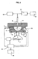
- the embodiment according to fig. 2 is the same as that of fig. 1, with the exception of the shape of chamber 1, which, rather than having a quadrilateral section, has a semi-circular section.
- a hemispherical shape, which is comprised in the embodiment shown, may be particularly advantageous in certain specific situations.
- FIG. 3 The embodiment of fig. 3 also has remarkable similarities with the previous ones. However, bore 5, rather than on chamber bottom 2, is found on one of walls 3. Chamber 1 has an elastic lower wall 18, which separates it from a gas-containing chamber 19, the pressure whereof is adjusted by devices 20 and 21, connected to data collection device 15.
- Fig. 5 diagrammatically shows a fourth embodiment of the present invention.
- the device comprises a measuring chamber 1, limited by a bottom 2 and by a side wall 3.
- the bottom 2 of chamber 1 has a bore 5 which carries a piston 22.
- Such piston is provided with an absolute sealing system (23), manufactured either conventionally (elastomer) or preferably by elastic deformation of the skirt which cancels the play between piston and bore, removing the measuring error due to elastomer deformation.
- a stopping device is associated with piston 22.
- Piston 22 is driven by a device 8 adjusting the position and its measurement, in turn connected to a computer 16.
- a temperature sensor 14, a pressure sensor 13, a mass flow meter 24 downstream of outlet system 25, a system 11 for the actuation of injector 9, housed at the top of chamber 1, a safety valve 26 and a thermostat 27 are also connected with computer 16.
- Mass flow meter 24 is connected with chamber 1 through an outlet pipe and outlet system 25.
- Safety valve 26 intercepts a pipe 28 coming from chamber 1, avoiding dangerous overpressures in case of malfunctioning. Finally, a bleeder vent 29 is provided at the top of chamber 1, which, in turn, is equipped with an interception valve, not shown in fig. 5.
- the embodiment of the device according to the invention shown in fig. 6 is fully similar to the one shown in fig. 5.
- the only actual difference is the inclination of chamber 1, the bottom 2 thereof, bore 5 and piston 22 with respect to the perpendicular to the ground, in order to aid chamber bleeding.
- the injector When it is intended to proceed to the measurement of fluid ejection from injector 9, said injector is placed in position in cover 4.
- the injection system consisting of feeding device 10, end stage 11 and central processing unit 12, causes a quantity of fluid to be ejected by injector 9.
- a pressure increase inside chamber 1 Such pressure increase is read by sensor 13 and sent to data collection device 15, together with the temperature value, measured by sensor 14.
- the data gathered by device 15 are sent to computer 16 which, from the pressure and temperature values, infers the fluid quantity, which is a function of these two parameters.
- step t 1 - t 2 of fig. 2 from bore 5 the fluid continuously flows into collection tank 7. Pressure therefore tends to decrease.
- step t 2 - t 3 of fig. 4 there is again ejection, with renewed pressure increase.
- computer 16 In order to obtain the value of the ejected quantity, computer 16 must obviously take into account the quantity discharged into collection tank 7. This quantity may be easily derived, since adjustment of the opening of bore 6 allows to achieve an outgoing flow rate which is a function of the pressure difference between the chambers upstream and downstream of the injector, hence the quantity still found in chamber 1 is a function of the opening and of the time, as is the quantity which has abandoned chamber 1.
- fluid features such as elastic modulus and compressibility are paramount. They must therefore be fed as data to computer 16.
- the embodiment shown in fig. 3 provides elastic wall 18.
- wall 18 In order to be able to operate elastically, wall 18 must be in contact with gas-containing chamber 19, the pressure of which is made to vary according to requirements, so as to reduce to a minimum the stresses on elastic wall 18.
- injector 9 is made to perform a cycle of injections sufficient to stabilise the system.
- Such pressure trend is read by sensor 13 and sent to computer 16, which also receives the temperature value, measured by sensor 14.
- Computer 16 from the pressure and temperature values, traces back the instant fluid flow rate, which is a function of these two parameters.
- outlet system 25 the fluid is discharged continuously, measuring the average discharge flow rate on a certain number of cycles with mass flow meter 24.
- computer 16 In order to derive the value of the actual flow rate ejected by the injector, computer 16 must obviously take into account the average flow rate discharged which is measured by mass flow meter 24.
- F C 0 ⁇ d ⁇ P d ⁇ T + C 1 2 + C 2 2 ⁇ P ⁇ P ⁇ ⁇ C 1
- the reckoning of C 0 is accomplished by calculating the pressure derivative with respect to the time in the cycle step in which the injector flow rate is nought.
- the method and the devices according to the present invention may be used in all the fields in which the calibration of an injector is important, in particular for the injectors of motorvehicle engines, for discontinuous flow rate nozzles and the like.
- the method and the device according to the present invention may be used for any type of fluid, in both liquid or gaseous state.
Landscapes
- Engineering & Computer Science (AREA)
- Physics & Mathematics (AREA)
- Fluid Mechanics (AREA)
- General Physics & Mathematics (AREA)
- Chemical & Material Sciences (AREA)
- Combustion & Propulsion (AREA)
- Mechanical Engineering (AREA)
- General Engineering & Computer Science (AREA)
- Measuring Volume Flow (AREA)
- Nozzles (AREA)
- Spray Control Apparatus (AREA)
Priority Applications (1)
| Application Number | Priority Date | Filing Date | Title |
|---|---|---|---|
| PL06117335T PL1746394T3 (pl) | 2005-07-20 | 2006-07-17 | Urządzenie do pomiaru ilości płynu wyrzucanego przez iniektor |
Applications Claiming Priority (2)
| Application Number | Priority Date | Filing Date | Title |
|---|---|---|---|
| IT000038A ITAN20050038A1 (it) | 2005-07-20 | 2005-07-20 | Dispositivo per la misurazione della quantita' di fluido emessa da un ugello |
| ITAN20060012 ITAN20060012A1 (it) | 2006-02-23 | 2006-02-23 | Metodo per la misurazione della quantita' di fluido emessa da un iniettore e dispositivo per eseguire la suddetta misurazione |
Publications (3)
| Publication Number | Publication Date |
|---|---|
| EP1746394A2 true EP1746394A2 (de) | 2007-01-24 |
| EP1746394A3 EP1746394A3 (de) | 2008-03-12 |
| EP1746394B1 EP1746394B1 (de) | 2010-09-22 |
Family
ID=37116032
Family Applications (1)
| Application Number | Title | Priority Date | Filing Date |
|---|---|---|---|
| EP06117335A Not-in-force EP1746394B1 (de) | 2005-07-20 | 2006-07-17 | Messgerät zur Messung der von einem Injektor eingepritzten Fluidmenge |
Country Status (4)
| Country | Link |
|---|---|
| EP (1) | EP1746394B1 (de) |
| AT (1) | ATE482379T1 (de) |
| DE (1) | DE602006017014D1 (de) |
| PL (1) | PL1746394T3 (de) |
Cited By (4)
| Publication number | Priority date | Publication date | Assignee | Title |
|---|---|---|---|---|
| WO2009019591A3 (en) * | 2007-08-09 | 2009-04-02 | Torino Politecnico | Method for determining the instantaneous flow rate of a fluid, in particular for a liquid under high-pressure |
| ITBO20080712A1 (it) * | 2008-11-27 | 2010-05-28 | Aea Srl | Metodo per misurare la portata istantanea di un iniettore per combustibili gassosi |
| CN104641103A (zh) * | 2012-09-19 | 2015-05-20 | Efs股份有限公司 | 用于测量喷射器喷射的流体量的设备 |
| CN113153601A (zh) * | 2021-05-08 | 2021-07-23 | 重庆红江机械有限责任公司 | 一种便于喷油器喷油量测定的稳定装置 |
Citations (1)
| Publication number | Priority date | Publication date | Assignee | Title |
|---|---|---|---|---|
| US5801308A (en) | 1996-03-07 | 1998-09-01 | Denso Corporation | Measuring apparatus for measuring an injected quantity of liquid |
Family Cites Families (6)
| Publication number | Priority date | Publication date | Assignee | Title |
|---|---|---|---|---|
| JPS614860A (ja) * | 1984-06-16 | 1986-01-10 | Mitsubishi Heavy Ind Ltd | 噴射率計 |
| JPS6463840A (en) * | 1987-09-03 | 1989-03-09 | Takemasa Kamimoto | Apparatus for measuring bulk-modulus of liquid |
| FR2795139B1 (fr) * | 1999-06-18 | 2001-07-20 | Efs Sa | Dispositif permettant d'analyser instantanement le debit d'injection coup par coup fourni par un systeme d'injection utilise dans un moteur thermique |
| DE10110649A1 (de) * | 2001-03-06 | 2002-09-26 | Bosch Gmbh Robert | Verfahren, Computerprogramm und Vorrichtung zum Messen der Einspritzmenge von Einspritzsystemen |
| DE10249754A1 (de) * | 2002-10-25 | 2004-05-06 | Robert Bosch Gmbh | Verfahren und Vorrichtung zur Messung der Einspritzrate eines Einspritzventils für Flüssigkeiten |
| US7197918B2 (en) * | 2003-08-14 | 2007-04-03 | International Engine Intellectual Property Company, Llc | Apparatus and method for evaluating fuel injectors |
-
2006
- 2006-07-17 AT AT06117335T patent/ATE482379T1/de not_active IP Right Cessation
- 2006-07-17 EP EP06117335A patent/EP1746394B1/de not_active Not-in-force
- 2006-07-17 DE DE602006017014T patent/DE602006017014D1/de active Active
- 2006-07-17 PL PL06117335T patent/PL1746394T3/pl unknown
Patent Citations (1)
| Publication number | Priority date | Publication date | Assignee | Title |
|---|---|---|---|---|
| US5801308A (en) | 1996-03-07 | 1998-09-01 | Denso Corporation | Measuring apparatus for measuring an injected quantity of liquid |
Cited By (6)
| Publication number | Priority date | Publication date | Assignee | Title |
|---|---|---|---|---|
| WO2009019591A3 (en) * | 2007-08-09 | 2009-04-02 | Torino Politecnico | Method for determining the instantaneous flow rate of a fluid, in particular for a liquid under high-pressure |
| ITBO20080712A1 (it) * | 2008-11-27 | 2010-05-28 | Aea Srl | Metodo per misurare la portata istantanea di un iniettore per combustibili gassosi |
| EP2192389A1 (de) | 2008-11-27 | 2010-06-02 | AEA S.r.l. | Verfahren zur Messung des Momentandurchflusses eines Kraftstoffinjektors für Brenngas |
| US7930930B2 (en) | 2008-11-27 | 2011-04-26 | Aea S.R.L. | Method for measuring the instantaneous flow of an injector for gaseous fuels |
| CN104641103A (zh) * | 2012-09-19 | 2015-05-20 | Efs股份有限公司 | 用于测量喷射器喷射的流体量的设备 |
| CN113153601A (zh) * | 2021-05-08 | 2021-07-23 | 重庆红江机械有限责任公司 | 一种便于喷油器喷油量测定的稳定装置 |
Also Published As
| Publication number | Publication date |
|---|---|
| ATE482379T1 (de) | 2010-10-15 |
| EP1746394A3 (de) | 2008-03-12 |
| DE602006017014D1 (de) | 2010-11-04 |
| EP1746394B1 (de) | 2010-09-22 |
| PL1746394T3 (pl) | 2011-03-31 |
Similar Documents
| Publication | Publication Date | Title |
|---|---|---|
| US7254993B2 (en) | Device for measuring time-resolved volumetric flow processes | |
| US6234148B1 (en) | Method and device for monitoring a pressure sensor | |
| EP1406005B1 (de) | Verfahren und Gerät für Überwachung von Steuerventilen | |
| US7896257B2 (en) | Fuel injector with real-time feedback control | |
| EP2786111B1 (de) | Kraftstoffeinspritzungsrückkoppelungssystem und verfahren | |
| US20050034514A1 (en) | Apparatus and method for evaluating fuel injectors | |
| CN101929394A (zh) | 燃料状态感测装置 | |
| JP2004518867A (ja) | 噴射システムの噴射量を測定するための方法、コンピュータプログラムおよび装置 | |
| JP5575264B2 (ja) | 噴射工程を測定するためのシステムおよび方法 | |
| US9132442B2 (en) | Diagnosis and controls of a fluid delivery apparatus with hydraulic buffer | |
| EP1746394B1 (de) | Messgerät zur Messung der von einem Injektor eingepritzten Fluidmenge | |
| CN108368815B (zh) | 用于确定喷射阀的喷射速率的方法和设备 | |
| CA2022169C (en) | Fuel control utilizing a multifunction valve | |
| US10584622B2 (en) | Expansion body and method for monitoring a pressure sensor in a SCR system with an expansion body | |
| EP0854976B1 (de) | Kombiniertes unter druck setzendes ventil, dosier- und flussverteilventil | |
| JP6144750B2 (ja) | 燃料噴射器 | |
| CN102137998B (zh) | 用于分析高功率热能发动机内所使用的燃料喷射系统提供的步进式喷射流率的方法 | |
| US7080550B1 (en) | Rate tube measurement system | |
| US6622545B2 (en) | Leak detection system and method having self-compensation for changes in pressurizing pump efficiency | |
| JP2006105656A (ja) | 流量計測装置および流量計測方法 | |
| JPH0681751A (ja) | 燃料噴射量・噴射率測定装置 | |
| WO1999067617A1 (en) | Flowmeter | |
| CN208254786U (zh) | 燃油分配管总成环境耐久试验装置 | |
| JP4821994B2 (ja) | ガスインジェクタの特性測定試験装置および特性測定試験方法 | |
| KR20160017293A (ko) | 액면레벨센서와 방향제어밸브를 이용한 연료분사율 측정장치 및 측정방법 |
Legal Events
| Date | Code | Title | Description |
|---|---|---|---|
| PUAI | Public reference made under article 153(3) epc to a published international application that has entered the european phase |
Free format text: ORIGINAL CODE: 0009012 |
|
| AK | Designated contracting states |
Kind code of ref document: A2 Designated state(s): AT BE BG CH CY CZ DE DK EE ES FI FR GB GR HU IE IS IT LI LT LU LV MC NL PL PT RO SE SI SK TR |
|
| AX | Request for extension of the european patent |
Extension state: AL BA HR MK YU |
|
| PUAL | Search report despatched |
Free format text: ORIGINAL CODE: 0009013 |
|
| AK | Designated contracting states |
Kind code of ref document: A3 Designated state(s): AT BE BG CH CY CZ DE DK EE ES FI FR GB GR HU IE IS IT LI LT LU LV MC NL PL PT RO SE SI SK TR |
|
| AX | Request for extension of the european patent |
Extension state: AL BA HR MK YU |
|
| 17P | Request for examination filed |
Effective date: 20080912 |
|
| 17Q | First examination report despatched |
Effective date: 20081009 |
|
| AKX | Designation fees paid |
Designated state(s): AT BE BG CH CY CZ DE DK EE ES FI FR GB GR HU IE IS IT LI LT LU LV MC NL PL PT RO SE SI SK TR |
|
| GRAP | Despatch of communication of intention to grant a patent |
Free format text: ORIGINAL CODE: EPIDOSNIGR1 |
|
| RTI1 | Title (correction) |
Free format text: DEVICE FOR MEASURING THE QUANTITY OF FLUID EJECTED BY AN INJECTOR |
|
| GRAS | Grant fee paid |
Free format text: ORIGINAL CODE: EPIDOSNIGR3 |
|
| GRAA | (expected) grant |
Free format text: ORIGINAL CODE: 0009210 |
|
| AK | Designated contracting states |
Kind code of ref document: B1 Designated state(s): AT BE BG CH CY CZ DE DK EE ES FI FR GB GR HU IE IS IT LI LT LU LV MC NL PL PT RO SE SI SK TR |
|
| REG | Reference to a national code |
Ref country code: GB Ref legal event code: FG4D |
|
| REG | Reference to a national code |
Ref country code: CH Ref legal event code: EP |
|
| REG | Reference to a national code |
Ref country code: IE Ref legal event code: FG4D |
|
| REF | Corresponds to: |
Ref document number: 602006017014 Country of ref document: DE Date of ref document: 20101104 Kind code of ref document: P |
|
| REG | Reference to a national code |
Ref country code: RO Ref legal event code: EPE |
|
| RAP2 | Party data changed (patent owner data changed or rights of a patent transferred) |
Owner name: AEA S.R.L. |
|
| PG25 | Lapsed in a contracting state [announced via postgrant information from national office to epo] |
Ref country code: AT Free format text: LAPSE BECAUSE OF FAILURE TO SUBMIT A TRANSLATION OF THE DESCRIPTION OR TO PAY THE FEE WITHIN THE PRESCRIBED TIME-LIMIT Effective date: 20100922 Ref country code: FI Free format text: LAPSE BECAUSE OF FAILURE TO SUBMIT A TRANSLATION OF THE DESCRIPTION OR TO PAY THE FEE WITHIN THE PRESCRIBED TIME-LIMIT Effective date: 20100922 Ref country code: LT Free format text: LAPSE BECAUSE OF FAILURE TO SUBMIT A TRANSLATION OF THE DESCRIPTION OR TO PAY THE FEE WITHIN THE PRESCRIBED TIME-LIMIT Effective date: 20100922 |
|
| REG | Reference to a national code |
Ref country code: NL Ref legal event code: VDEP Effective date: 20100922 |
|
| LTIE | Lt: invalidation of european patent or patent extension |
Effective date: 20100922 |
|
| PG25 | Lapsed in a contracting state [announced via postgrant information from national office to epo] |
Ref country code: SI Free format text: LAPSE BECAUSE OF FAILURE TO SUBMIT A TRANSLATION OF THE DESCRIPTION OR TO PAY THE FEE WITHIN THE PRESCRIBED TIME-LIMIT Effective date: 20100922 |
|
| PG25 | Lapsed in a contracting state [announced via postgrant information from national office to epo] |
Ref country code: LV Free format text: LAPSE BECAUSE OF FAILURE TO SUBMIT A TRANSLATION OF THE DESCRIPTION OR TO PAY THE FEE WITHIN THE PRESCRIBED TIME-LIMIT Effective date: 20100922 Ref country code: SE Free format text: LAPSE BECAUSE OF FAILURE TO SUBMIT A TRANSLATION OF THE DESCRIPTION OR TO PAY THE FEE WITHIN THE PRESCRIBED TIME-LIMIT Effective date: 20100922 Ref country code: GR Free format text: LAPSE BECAUSE OF FAILURE TO SUBMIT A TRANSLATION OF THE DESCRIPTION OR TO PAY THE FEE WITHIN THE PRESCRIBED TIME-LIMIT Effective date: 20101223 |
|
| REG | Reference to a national code |
Ref country code: PL Ref legal event code: T3 |
|
| REG | Reference to a national code |
Ref country code: HU Ref legal event code: AG4A Ref document number: E009851 Country of ref document: HU |
|
| PG25 | Lapsed in a contracting state [announced via postgrant information from national office to epo] |
Ref country code: CZ Free format text: LAPSE BECAUSE OF FAILURE TO SUBMIT A TRANSLATION OF THE DESCRIPTION OR TO PAY THE FEE WITHIN THE PRESCRIBED TIME-LIMIT Effective date: 20100922 Ref country code: IS Free format text: LAPSE BECAUSE OF FAILURE TO SUBMIT A TRANSLATION OF THE DESCRIPTION OR TO PAY THE FEE WITHIN THE PRESCRIBED TIME-LIMIT Effective date: 20110122 Ref country code: PT Free format text: LAPSE BECAUSE OF FAILURE TO SUBMIT A TRANSLATION OF THE DESCRIPTION OR TO PAY THE FEE WITHIN THE PRESCRIBED TIME-LIMIT Effective date: 20110124 Ref country code: EE Free format text: LAPSE BECAUSE OF FAILURE TO SUBMIT A TRANSLATION OF THE DESCRIPTION OR TO PAY THE FEE WITHIN THE PRESCRIBED TIME-LIMIT Effective date: 20100922 Ref country code: SK Free format text: LAPSE BECAUSE OF FAILURE TO SUBMIT A TRANSLATION OF THE DESCRIPTION OR TO PAY THE FEE WITHIN THE PRESCRIBED TIME-LIMIT Effective date: 20100922 Ref country code: NL Free format text: LAPSE BECAUSE OF FAILURE TO SUBMIT A TRANSLATION OF THE DESCRIPTION OR TO PAY THE FEE WITHIN THE PRESCRIBED TIME-LIMIT Effective date: 20100922 |
|
| PG25 | Lapsed in a contracting state [announced via postgrant information from national office to epo] |
Ref country code: BE Free format text: LAPSE BECAUSE OF FAILURE TO SUBMIT A TRANSLATION OF THE DESCRIPTION OR TO PAY THE FEE WITHIN THE PRESCRIBED TIME-LIMIT Effective date: 20100922 |
|
| PG25 | Lapsed in a contracting state [announced via postgrant information from national office to epo] |
Ref country code: ES Free format text: LAPSE BECAUSE OF FAILURE TO SUBMIT A TRANSLATION OF THE DESCRIPTION OR TO PAY THE FEE WITHIN THE PRESCRIBED TIME-LIMIT Effective date: 20110102 |
|
| PLBE | No opposition filed within time limit |
Free format text: ORIGINAL CODE: 0009261 |
|
| STAA | Information on the status of an ep patent application or granted ep patent |
Free format text: STATUS: NO OPPOSITION FILED WITHIN TIME LIMIT |
|
| 26N | No opposition filed |
Effective date: 20110623 |
|
| PG25 | Lapsed in a contracting state [announced via postgrant information from national office to epo] |
Ref country code: DK Free format text: LAPSE BECAUSE OF FAILURE TO SUBMIT A TRANSLATION OF THE DESCRIPTION OR TO PAY THE FEE WITHIN THE PRESCRIBED TIME-LIMIT Effective date: 20100922 |
|
| REG | Reference to a national code |
Ref country code: DE Ref legal event code: R097 Ref document number: 602006017014 Country of ref document: DE Effective date: 20110623 |
|
| PG25 | Lapsed in a contracting state [announced via postgrant information from national office to epo] |
Ref country code: MC Free format text: LAPSE BECAUSE OF NON-PAYMENT OF DUE FEES Effective date: 20110731 |
|
| REG | Reference to a national code |
Ref country code: CH Ref legal event code: PL |
|
| REG | Reference to a national code |
Ref country code: IE Ref legal event code: MM4A |
|
| PG25 | Lapsed in a contracting state [announced via postgrant information from national office to epo] |
Ref country code: LI Free format text: LAPSE BECAUSE OF NON-PAYMENT OF DUE FEES Effective date: 20110731 Ref country code: CH Free format text: LAPSE BECAUSE OF NON-PAYMENT OF DUE FEES Effective date: 20110731 |
|
| PG25 | Lapsed in a contracting state [announced via postgrant information from national office to epo] |
Ref country code: IE Free format text: LAPSE BECAUSE OF NON-PAYMENT OF DUE FEES Effective date: 20110717 |
|
| PGFP | Annual fee paid to national office [announced via postgrant information from national office to epo] |
Ref country code: PL Payment date: 20120711 Year of fee payment: 7 |
|
| PG25 | Lapsed in a contracting state [announced via postgrant information from national office to epo] |
Ref country code: CY Free format text: LAPSE BECAUSE OF EXPIRATION OF PROTECTION Effective date: 20100922 |
|
| PG25 | Lapsed in a contracting state [announced via postgrant information from national office to epo] |
Ref country code: TR Free format text: LAPSE BECAUSE OF FAILURE TO SUBMIT A TRANSLATION OF THE DESCRIPTION OR TO PAY THE FEE WITHIN THE PRESCRIBED TIME-LIMIT Effective date: 20100922 Ref country code: BG Free format text: LAPSE BECAUSE OF FAILURE TO SUBMIT A TRANSLATION OF THE DESCRIPTION OR TO PAY THE FEE WITHIN THE PRESCRIBED TIME-LIMIT Effective date: 20101222 |
|
| REG | Reference to a national code |
Ref country code: PL Ref legal event code: LAPE |
|
| PG25 | Lapsed in a contracting state [announced via postgrant information from national office to epo] |
Ref country code: PL Free format text: LAPSE BECAUSE OF NON-PAYMENT OF DUE FEES Effective date: 20130717 |
|
| PGFP | Annual fee paid to national office [announced via postgrant information from national office to epo] |
Ref country code: HU Payment date: 20140624 Year of fee payment: 9 |
|
| PG25 | Lapsed in a contracting state [announced via postgrant information from national office to epo] |
Ref country code: HU Free format text: LAPSE BECAUSE OF NON-PAYMENT OF DUE FEES Effective date: 20150718 |
|
| REG | Reference to a national code |
Ref country code: FR Ref legal event code: PLFP Year of fee payment: 11 |
|
| PGFP | Annual fee paid to national office [announced via postgrant information from national office to epo] |
Ref country code: RO Payment date: 20160715 Year of fee payment: 11 |
|
| REG | Reference to a national code |
Ref country code: FR Ref legal event code: PLFP Year of fee payment: 12 |
|
| PG25 | Lapsed in a contracting state [announced via postgrant information from national office to epo] |
Ref country code: RO Free format text: LAPSE BECAUSE OF NON-PAYMENT OF DUE FEES Effective date: 20170717 |
|
| REG | Reference to a national code |
Ref country code: FR Ref legal event code: PLFP Year of fee payment: 13 |
|
| PGFP | Annual fee paid to national office [announced via postgrant information from national office to epo] |
Ref country code: LU Payment date: 20200727 Year of fee payment: 15 |
|
| PGFP | Annual fee paid to national office [announced via postgrant information from national office to epo] |
Ref country code: FR Payment date: 20210726 Year of fee payment: 16 |
|
| PGFP | Annual fee paid to national office [announced via postgrant information from national office to epo] |
Ref country code: GB Payment date: 20210726 Year of fee payment: 16 |
|
| PGFP | Annual fee paid to national office [announced via postgrant information from national office to epo] |
Ref country code: IT Payment date: 20210701 Year of fee payment: 16 |
|
| PG25 | Lapsed in a contracting state [announced via postgrant information from national office to epo] |
Ref country code: LU Free format text: LAPSE BECAUSE OF NON-PAYMENT OF DUE FEES Effective date: 20210717 |
|
| GBPC | Gb: european patent ceased through non-payment of renewal fee |
Effective date: 20220717 |
|
| PG25 | Lapsed in a contracting state [announced via postgrant information from national office to epo] |
Ref country code: FR Free format text: LAPSE BECAUSE OF NON-PAYMENT OF DUE FEES Effective date: 20220731 |
|
| PG25 | Lapsed in a contracting state [announced via postgrant information from national office to epo] |
Ref country code: GB Free format text: LAPSE BECAUSE OF NON-PAYMENT OF DUE FEES Effective date: 20220717 |
|
| P01 | Opt-out of the competence of the unified patent court (upc) registered |
Effective date: 20230329 |
|
| PG25 | Lapsed in a contracting state [announced via postgrant information from national office to epo] |
Ref country code: IT Free format text: LAPSE BECAUSE OF NON-PAYMENT OF DUE FEES Effective date: 20220717 |
|
| PGFP | Annual fee paid to national office [announced via postgrant information from national office to epo] |
Ref country code: DE Payment date: 20230726 Year of fee payment: 18 |
|
| REG | Reference to a national code |
Ref country code: DE Ref legal event code: R119 Ref document number: 602006017014 Country of ref document: DE |
|
| PG25 | Lapsed in a contracting state [announced via postgrant information from national office to epo] |
Ref country code: DE Free format text: LAPSE BECAUSE OF NON-PAYMENT OF DUE FEES Effective date: 20250201 |