EP1745948A1 - Textile and elastic anti-skid device for vehicle tyres - Google Patents
Textile and elastic anti-skid device for vehicle tyres Download PDFInfo
- Publication number
- EP1745948A1 EP1745948A1 EP05425528A EP05425528A EP1745948A1 EP 1745948 A1 EP1745948 A1 EP 1745948A1 EP 05425528 A EP05425528 A EP 05425528A EP 05425528 A EP05425528 A EP 05425528A EP 1745948 A1 EP1745948 A1 EP 1745948A1
- Authority
- EP
- European Patent Office
- Prior art keywords
- tyre
- belt
- elastic means
- tread
- width
- Prior art date
- Legal status (The legal status is an assumption and is not a legal conclusion. Google has not performed a legal analysis and makes no representation as to the accuracy of the status listed.)
- Granted
Links
- 239000004753 textile Substances 0.000 title description 2
- 239000000463 material Substances 0.000 claims description 25
- 229920001971 elastomer Polymers 0.000 claims description 11
- 229920000728 polyester Polymers 0.000 claims description 10
- 239000004743 Polypropylene Substances 0.000 claims description 9
- -1 polypropylene Polymers 0.000 claims description 9
- 229920001155 polypropylene Polymers 0.000 claims description 9
- 239000000203 mixture Substances 0.000 claims description 8
- 238000009958 sewing Methods 0.000 claims description 8
- 239000000806 elastomer Substances 0.000 claims description 6
- 239000004952 Polyamide Substances 0.000 claims description 5
- 229920002647 polyamide Polymers 0.000 claims description 5
- 238000009941 weaving Methods 0.000 claims description 5
- 239000004677 Nylon Substances 0.000 claims description 4
- 229920001778 nylon Polymers 0.000 claims description 4
- 239000005062 Polybutadiene Substances 0.000 claims description 3
- 239000013013 elastic material Substances 0.000 claims description 3
- 229920001084 poly(chloroprene) Polymers 0.000 claims description 3
- 229920002857 polybutadiene Polymers 0.000 claims description 3
- 241000531908 Aramides Species 0.000 claims description 2
- 229920003235 aromatic polyamide Polymers 0.000 claims description 2
- 238000004519 manufacturing process Methods 0.000 description 8
- 239000000835 fiber Substances 0.000 description 5
- 239000005060 rubber Substances 0.000 description 5
- 239000011248 coating agent Substances 0.000 description 3
- 238000000576 coating method Methods 0.000 description 3
- 230000007246 mechanism Effects 0.000 description 3
- 230000002093 peripheral effect Effects 0.000 description 3
- 239000010426 asphalt Substances 0.000 description 2
- 231100001261 hazardous Toxicity 0.000 description 2
- 229920006149 polyester-amide block copolymer Polymers 0.000 description 2
- 238000005096 rolling process Methods 0.000 description 2
- 230000008961 swelling Effects 0.000 description 2
- 230000002522 swelling effect Effects 0.000 description 2
- 244000025254 Cannabis sativa Species 0.000 description 1
- 235000012766 Cannabis sativa ssp. sativa var. sativa Nutrition 0.000 description 1
- 235000012765 Cannabis sativa ssp. sativa var. spontanea Nutrition 0.000 description 1
- 229920001468 Cordura Polymers 0.000 description 1
- 235000009120 camo Nutrition 0.000 description 1
- 235000005607 chanvre indien Nutrition 0.000 description 1
- 238000000151 deposition Methods 0.000 description 1
- 230000000694 effects Effects 0.000 description 1
- 239000004744 fabric Substances 0.000 description 1
- 239000011487 hemp Substances 0.000 description 1
- 230000002452 interceptive effect Effects 0.000 description 1
- 238000000034 method Methods 0.000 description 1
- 238000012986 modification Methods 0.000 description 1
- 230000004048 modification Effects 0.000 description 1
- 239000008188 pellet Substances 0.000 description 1
- 239000004814 polyurethane Substances 0.000 description 1
- 229920003225 polyurethane elastomer Polymers 0.000 description 1
Images


Classifications
-
- B—PERFORMING OPERATIONS; TRANSPORTING
- B60—VEHICLES IN GENERAL
- B60C—VEHICLE TYRES; TYRE INFLATION; TYRE CHANGING; CONNECTING VALVES TO INFLATABLE ELASTIC BODIES IN GENERAL; DEVICES OR ARRANGEMENTS RELATED TO TYRES
- B60C27/00—Non-skid devices temporarily attachable to resilient tyres or resiliently-tyred wheels
- B60C27/06—Non-skid devices temporarily attachable to resilient tyres or resiliently-tyred wheels extending over the complete circumference of the tread, e.g. made of chains or cables
- B60C27/16—Non-skid devices temporarily attachable to resilient tyres or resiliently-tyred wheels extending over the complete circumference of the tread, e.g. made of chains or cables formed of close material, e.g. leather or synthetic mats
- B60C27/18—Non-skid devices temporarily attachable to resilient tyres or resiliently-tyred wheels extending over the complete circumference of the tread, e.g. made of chains or cables formed of close material, e.g. leather or synthetic mats the material being fabric, e.g. woven wire or textile
Definitions
- This invention relates to a device which is capable of increasing the grip of a vehicle tyre in the presence of surfaces having a low friction coefficient according to the precharacterising clause of claim 1.
- patent US 2682907 describes a skid-prevention device comprising a belt or strip of rough hemp which can be positioned on the outer surface of a vehicle tyre.
- the strip is provided with lateral bands which are positioned on the outer and inner shoulders of the tyre, where an elastic member is provided to tension the belt.
- Another device for preventing the skidding of a vehicle tyre on surfaces having a low friction coefficient is known from Japanese patent JP1249503 , in which an anti-skid belt of a particular width such as to surround the tread of the tyre and having a predetermined play (or gap) between the strip and the tread of the tyre is illustrated.
- This belt as described by the text of the patent is capable of providing better grip to the road surface when the tyre is rotating.
- the non-skid belt comprises blocks of rubber which are in contact with the ground surface and lateral bands surrounding the inner and outer shoulders of the tyre respectively, with a view to at least ideally preventing loss of the belt during rotation of the tyre.
- the specified aim of this application is to provide a device for covering a tyre which can be fitted to a vehicle wheel even when the wheel is standing on the ground.
- the inner circumference of the device must be such that it must be 4 to 10% and preferably 5 to 6% larger than the greater circumference of the tyre.
- the text of the patent also teaches that the device is provided with lateral bands which are positioned on the outer and inner shoulders of the tyre, where an elastic member is provided to tension the belt.
- This slip may result in rotation of the tyre within the device without sufficient grip or grip on the part of the device on the surface, or sufficient grip to permit movement of the vehicle.
- Such a device may have the further problem of accidental loss during rotation of the tyre, giving rise to more than negligible economic loss to the user.
- the object of this invention is to overcome the problems illustrated above with reference to the documents in the known art.
- this object is accomplished through a device which is capable of increasing the grip of a vehicle tyre in the presence of surfaces having a low friction coefficient such as snow, ice and mud in accordance with the characterising part of claim 1.
- Another advantage of this invention is to produce deformation of the surface of the fabric in such a way as to increase the anti-skid effect.
- Another advantage of this invention is that of providing a device which is simple and economical to manufacture, is noise-free and has no vibration when the vehicle is in motion on road surfaces devoid of snow, ice or mud.
- the device according to the invention is very simple to install and remove from the tyre.
- 1 indicates as a whole the device capable of increasing the grip of a tyre 2 of a vehicle (not shown in the appended figures) in the presence of surfaces having a low friction coefficient such as snow, ice or mud, according to the invention.
- Device 1 comprises a belt 3 which is capable of surrounding the entire width "L" of the tread of tyre 2 in such a way as to enclose or circumscribe it with a predetermined play.
- Belt 3 has outer 4 and inner 5 side portions capable of surrounding the outer 2A and inner 2B shoulders of said tyre 2 respectively.
- These side portions 4 and 5 can advantageously extend radially so as to assist fitting of device 1 to tyre 2.
- both the inner 5 and outer 4 side portions of belt 3 have an elastic member 6A and 6B respectively capable of holding belt 3 in the correct fitted position while tyre 2 rotates.
- belt 3 has only one elastic member 6A capable of holding it in position at least on the inner side of shoulder 2B of tyre 2.
- the materials used to construct belt 3 according to this invention may be:
- the inner surface of belt 3, that is the surface of belt 3 against the tread of tyre 2 may advantageously be treated in such a way as to have rubber members deposited upon it in the form of "pellets” (a technique usually called “dot coating”).
- This treatment of the inner surface of belt 3 encourages better grip between belt 3 and the tread of tyre 2 so as to restrict if not eliminate slip of tyre 2 with respect to belt 3 in the presence of surfaces having a very low friction coefficient.
- these rubber members may be deposited on the outer surface of belt 3 (not illustrated in the appended figures), that is on the surface of belt 3 which is in contact with the surface.
- the material used for depositing the dot coating of the aforesaid rubber members according to this invention may be polyurethane, or butadiene rubber or neoprene rubber and the like.
- belt 3 has outer 4 and inner 5 side portions which can extend radially to enclose the outer 2A and inner 2B shoulders of said tyre 2 respectively.
- These side portions 4 and 5 comprise a material which is lighter and more flexible and has a lower friction coefficient than the material comprising belt 3.
- outer 4 and inner 5 side portions are directly woven with belt 3 in each longitudinal profile.
- outer 4 and inner 5 side portions of belt 3 partly enclose outer 2A and inner 2B shoulders of said tyre 2 respectively.
- outer 4 and inner 5 side portions may be:
- outer 4 and inner 5 side portions comprise elastic members 6A and 6B.
- elastic members 6A and 6B The function of elastic members 6A and 6B is to ensure that accidental loss of device 1 from tyre 2 while the latter is in rotation will not occur.
- the materials used to manufacture elastic members 6A and 6B according to this invention may be:
- belt 3 comprises a circumferential portion 11 provided with elastic means 7.
- These elastic means 7 are advantageously capable of causing said circumferential portion 11 to adhere to the tread surface of said tyre 2.
- circumferential portion 11 of belt 3 extends axially along the axis of rotation X-X of tyre 2.
- Elastic means 7 take the form of an elastic belt having a width "1" equal to or 4% larger than the width "L" of the tread of tyre 2, preferably a width "1" within a range of 4 to 18% with respect to the width of tyre 2.
- the width of circumferential portion 11 is therefore preferably equal to the width "1" of elastic means 7.
- This surface deformation of belt 3 is capable of increasing the grip of the belt in the presence of surfaces having a low friction coefficient, in that the surface area of device 1 in contact with the surface is increased.
- device 1 is advantageously prevented from interfering with mechanical parts or the bodywork of the vehicle.
- Elastic means 7 should therefore be capable of adhering closely to the tread of tyre 2, which involves providing elastic means of different circumference and different elasticity to adhere to different sizes of tyre.
- the width "1" of elastic means 7, according to the values described above, must be greater than or equal to 7.8 mm and preferably must lie within the range from 7.8 mm to 35.1 mm.
- the width of circumferential portion 11 of belt 3 must be greater than or equal to 7.8 mm, and preferably should lie within the range from 7.8 mm to 35.1 mm.
- elastic means 7 also makes it possible to increase the number of tyre sizes which device 1 according to this invention will fit.
- two or more elastic belts which might also have different widths, alternating with the material comprising belt 3 may be provided.
- belt 3 comprises two circumferential portions 13, each of which is provided with elastic means 7.
- Elastic means 7 take the form of a pair of elastic belts having widths "11" and "12" which are capable of causing circumferential portions 13 to adhere to the surface of the tread of said tyre 2.
- the sum of the widths "11” and “12”, that is “11” and in addition “12”, may be equal to or greater than 4% of the width "L" of tyre 2, preferably lying within the range from 4 to 18% of the width "L” of the tread of tyre 2.
- elastic means 7 are constructed in such a way as to be in direct contact with the tread of tyre 2.
- This arrangement provides optimum protection of the elastic belt against wear due to the rolling of tyre 2 on surfaces having a high friction coefficient, such as for example an asphalt road surface.
- FIGS. 4 and 5 illustrate a further two arrangements of elastic means 7 according to this invention.
- elastic means 7 are in direct contact with the road surface, that is they are located on the outer surface of belt 3.
- the elastic belt is subjected to special antiabrasion treatment which permits limited wear when the tyre is running on surfaces having a high friction coefficient, such as for example an asphalt road surface.
- width "1" of elastic means 7 must be equal to or greater than 4% of width "L" of tyre 2, preferably lying within the range from 4 to 18% of the width "L" of the tread of tyre 2.
- elastic means 7 are obtained by inserting one or more threads 10 of elastic material grouped together to form the elastic belt through weaving operations in the material comprising belt 3.
- threads 10 of elastic material constitute a set of circumferentially tensioned threads designed to cross the warp of the material comprising belt 3. This arrangement ensures greater reliability in terms of the service life of device 1.
- the overall width of threads 10 must be equal to or greater than 4% of the width "L" of tyre 2, preferably lying within the range from 4 to 18% of the width "L" of the tread of tyre 2.
- elastic means 7 described hitherto are capable of surrounding the entire circumference of the tread of tyre 2, but in an alternative embodiment of this invention (not illustrated in these figures) elastic means 7 may run along a circumferential portion of the tread of tyre 2.
- elastic means 7 that is the elastic belt ( Figures 1 or 7) or the elastic belts ( Figure 6), run circumferentially over only a portion of the overall circumference of tyre 2.
- This specific embodiment is more economical to manufacture in that it provides for use of less material for the manufacture of elastic means 7.
- the materials used for the manufacture of elastic means 7 according to this invention may be:
- device 1 comprises two strips 8 (or braces) at right angles on the outer side which extend diametrically.
- These strips 8 may be connected directly to belt 3 by a sewing operation. It should be noted that in the area where the two strips 8 cross there is further sewing to connect the strips together.
- Strips 8 are useful when a user desires to remove device 1 from tyre 2, because these offer an easy and secure grip.
- three strips arranged in a star-type configuration with three points are provided instead of two strips at right angles. In the area where the three strips 8 cross there is further sewing to connect the strips together.
- the materials used to manufacture strips 8 according to this invention may be:
- the circumferential portion 11 of strip 3 comprises a sheath (or pocket) 9 which preferably extends over the entire circumference of tyre 2.
- this sheath 9 is connected to the material comprising belt 3 through a sewing or weaving operation.
- sheath 9 can be constructed using the same materials as comprising belt 3, or different materials.
- sheath 9 has an axial width "T" along the axis of rotation X-X which is greater than or equal to the width "1" of elastic means 7.
- circumferential portion 11 of belt 3 has an axial width equal to the axial width "T" of sheath 9, or an axial width which is greater than the width "1" of elastic means 7.
Landscapes
- Engineering & Computer Science (AREA)
- Textile Engineering (AREA)
- Mechanical Engineering (AREA)
- Tires In General (AREA)
- Woven Fabrics (AREA)
Abstract
Description
- This invention relates to a device which is capable of increasing the grip of a vehicle tyre in the presence of surfaces having a low friction coefficient according to the precharacterising clause of
claim 1. - Devices capable of increasing the grip of a vehicle tyre in the case of surfaces having a low friction coefficient, such as for example snow, ice or mud, are known in the state of the art.
- For example, patent
US 2682907 describes a skid-prevention device comprising a belt or strip of rough hemp which can be positioned on the outer surface of a vehicle tyre. In particular the strip is provided with lateral bands which are positioned on the outer and inner shoulders of the tyre, where an elastic member is provided to tension the belt. - The text of patent
US 2682907 subsequently discloses that the belt is constructed in such a way that it can be applied closely to the tread of the tyre. This feature obviously requires that the vehicle's wheel be first lifted off the ground in order for the belt to be positioned on the tyre. - Another problem occurring in the case of the invention described in the abovementioned patent derives from the fact that the belt may become accidentally detached from the tyre towards the vehicle's interior. In this way it could create a hazardous situation in that the inwardly moving belt could interfere with the vehicle's steering and braking mechanisms, with obvious and imaginable consequences. When a situation of this type arises the wheel must first be removed in order to remove the belt or the belt must be destroyed.
- Another device for preventing the skidding of a vehicle tyre on surfaces having a low friction coefficient is known from
Japanese patent JP1249503 - This belt as described by the text of the patent is capable of providing better grip to the road surface when the tyre is rotating.
- In particular the non-skid belt comprises blocks of rubber which are in contact with the ground surface and lateral bands surrounding the inner and outer shoulders of the tyre respectively, with a view to at least ideally preventing loss of the belt during rotation of the tyre.
- However the presence of these rubber blocks on the outer surface of the anti-skid belt or on the surface in contact with the road surface only partly solves the problem of grip in the presence of surfaces having a low friction coefficient.
- In fact it is obvious that such an anti-skid belt has as its main function that of preserving the integrity of the tyre's tread and of causing the least possible damage to the road surface when the vehicle is in motion.
- Another example of a device capable of increasing the grip of a tyre in the presence of surfaces having a low friction coefficient is described in patent application
WO 00/59745 - The specified aim of this application is to provide a device for covering a tyre which can be fitted to a vehicle wheel even when the wheel is standing on the ground. In order for it to be possible to achieve this object it is described that the inner circumference of the device must be such that it must be 4 to 10% and preferably 5 to 6% larger than the greater circumference of the tyre.
- The text of the patent also teaches that the device is provided with lateral bands which are positioned on the outer and inner shoulders of the tyre, where an elastic member is provided to tension the belt.
- Again this type of device is not devoid of disadvantages, even though it permits easier and more immediate fitting than the devices in the known art.
- In fact while the tyre is rolling there is the possibility that the device, being larger than the major circumference of the tyre, might interfere with the wheel arch or the steering and traction mechanisms.
- This eventuality could give rise to early wear of the device and in the worst of situations damage which would prevent its use.
- This happens because of the fact that, because the device is constructed of a textile material, it undergoes a kind of swelling as the tyre rotates because of the centrifugal force. It is precisely because of the swelling of the material that there may be interference with the wheel arch or with the vehicle's steering and traction mechanisms.
- It is obvious that the larger the device in comparison with the outer circumference of the tyre, the more easily the phenomena described above will occur.
- Another problem which may arise if the device is adopted as described in patent application
WO 00/59745 - In fact when the friction coefficient of the surface is particularly low, for example in the case of icy snow or ice, there is the possibility that a difference in rotation speed will be set up between the tyre and the device, that is mutual slip between the tyre and the device.
- This slip may result in rotation of the tyre within the device without sufficient grip or grip on the part of the device on the surface, or sufficient grip to permit movement of the vehicle.
- This disadvantage is due to the fact that the device is only held on the wheel by the elastic member positioned on the inner lateral band of the device.
- Finally, such a device may have the further problem of accidental loss during rotation of the tyre, giving rise to more than negligible economic loss to the user.
- In the light of the state of the art described the object of this invention is to overcome the problems illustrated above with reference to the documents in the known art.
- According to this invention this object is accomplished through a device which is capable of increasing the grip of a vehicle tyre in the presence of surfaces having a low friction coefficient such as snow, ice and mud in accordance with the characterising part of
claim 1. - Through this invention it is possible to provide a device capable of increasing the grip of a vehicle tyre without any risk of the device coming loose during rotation of the tyre.
- Another advantage of this invention is to produce deformation of the surface of the fabric in such a way as to increase the anti-skid effect.
- There is also the not insignificant advantage that through the presence of the elastic means it is possible to reduce the swelling effect which occurs when the vehicle is in motion, thus avoiding hazardous rubbing against mechanical parts or parts of the bodywork.
- Another advantage of this invention is that of providing a device which is simple and economical to manufacture, is noise-free and has no vibration when the vehicle is in motion on road surfaces devoid of snow, ice or mud.
- Finally, the device according to the invention is very simple to install and remove from the tyre.
- The features and advantages of this invention will be apparent from the following detailed description of a number of embodiments illustrated by way of non-restrictive examples in the appended drawings, in which:
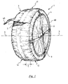
- Figure 1 shows a perspective view in partial cross-section of an embodiment of the device according to this invention when fitted to a vehicle tyre,
- Figure 2 shows a view in cross-section of the embodiment of the device in Figure 1,
- Figure 3 shows another embodiment of the device according to the invention,
- Figure 4 shows another embodiment of the device according to the invention,
- Figure 5 shows a further embodiment of the device according to the invention,
- Figure 6 shows another perspective view of another embodiment of the device when fitted to a vehicle tyre according to the invention,
- Figure 7 shows another perspective view of another embodiment of the device when fitted to a vehicle tyre according to the invention.
- With reference to the appended figures, 1 indicates as a whole the device capable of increasing the grip of a
tyre 2 of a vehicle (not shown in the appended figures) in the presence of surfaces having a low friction coefficient such as snow, ice or mud, according to the invention. -
Device 1 comprises abelt 3 which is capable of surrounding the entire width "L" of the tread oftyre 2 in such a way as to enclose or circumscribe it with a predetermined play.
Belt 3 has outer 4 and inner 5 side portions capable of surrounding the outer 2A and inner 2B shoulders of saidtyre 2 respectively. - These
side portions 4 and 5 can advantageously extend radially so as to assist fitting ofdevice 1 totyre 2. - Thus once mounted on
tyre 2belt 3 has a transverse extension which is at least equal to the width "L" of the tread oftyre 2. - It should be noted that, as illustrated in detail in Figure 2, both the inner 5 and outer 4 side portions of
belt 3 have anelastic member belt 3 in the correct fitted position whiletyre 2 rotates. - Alternatively it is provided that
belt 3 has only oneelastic member 6A capable of holding it in position at least on the inner side ofshoulder 2B oftyre 2. - The materials used to construct
belt 3 according to this invention may be: - high strength polyester fibres or yarns, which may or may not take a dye,
- polypropylene, which also may or may not take a dye,
- taslanised polypropylene, which also may or may not take a dye,
- variable compositions of various fibres, such as for example 50% polyester with 50% polypropylene, or 50% taslanised polypropylene,
- para and meta aramide fibres,
- high strength polyamide fibres such as nylon, cordura, etc., in order to extend the service life of the device.
- Obviously a person skilled in the art will be able to replace the abovementioned materials for the manufacture of
belt 3 by other types of structurally and/or functionally equivalent materials. - It should be noted that the inner surface of
belt 3, that is the surface ofbelt 3 against the tread oftyre 2, may advantageously be treated in such a way as to have rubber members deposited upon it in the form of "pellets" (a technique usually called "dot coating"). - This treatment of the inner surface of
belt 3 encourages better grip betweenbelt 3 and the tread oftyre 2 so as to restrict if not eliminate slip oftyre 2 with respect to belt 3 in the presence of surfaces having a very low friction coefficient. - Advantageously it is also provided that these rubber members ("dot coating") may be deposited on the outer surface of belt 3 (not illustrated in the appended figures), that is on the surface of
belt 3 which is in contact with the surface. - This treatment of the outer surface of
belt 3 favours the following properties: - better stability of
belt 3 with respect to the transverse forces which are generated during movement of the tyre when the vehicle is travelling through a bend, such as to prevent the accidental loss ofdevice 1 fromtyre 2, - better grip for
belt 3 in the presence of surfaces having a very low friction coefficient, such as to further increase grip on snow and ice beyond that ensured by the materials (previously listed) constitutingbelt 3. - The material used for depositing the dot coating of the aforesaid rubber members according to this invention may be polyurethane, or butadiene rubber or neoprene rubber and the like.
- As already described,
belt 3 has outer 4 and inner 5 side portions which can extend radially to enclose the outer 2A and inner 2B shoulders of saidtyre 2 respectively. - These
side portions 4 and 5 comprise a material which is lighter and more flexible and has a lower friction coefficient than thematerial comprising belt 3. - It should be noted that outer 4 and inner 5 side portions are directly woven with
belt 3 in each longitudinal profile. - Obviously a person skilled in the art may provide other structurally and/or functionally equivalent types of operations as a replacement for the sewing operation between the outer 4 and inner 5 side portions and
belt 3. - In the preferred embodiment outer 4 and inner 5 side portions of
belt 3 partly enclose outer 2A and inner 2B shoulders of saidtyre 2 respectively. - The materials used to manufacture outer 4 and inner 5 side portions according to this invention may be:
- fibre having a low friction coefficient,
- polyester,
- polypropylene,
- butadiene rubber, and
- neoprene rubber.
- These materials make it easier for a user to fit
device 1 ontyre 2 in the operations of fitting the same, as it can be easily stretched by the user. - As previously described, outer 4 and inner 5 side portions comprise
elastic members - These
elastic members side portions 4 and 5 through a sewing operation. - The function of
elastic members device 1 fromtyre 2 while the latter is in rotation will not occur. - The materials used to manufacture
elastic members - elastomer fibre compositions with polyester,
- elastomer fibre compositions with nylon polyester or polyamide.
- The essential feature of this invention is that
belt 3 comprises acircumferential portion 11 provided withelastic means 7. - These
elastic means 7 are advantageously capable of causing saidcircumferential portion 11 to adhere to the tread surface of saidtyre 2. - In particular
circumferential portion 11 ofbelt 3 extends axially along the axis of rotation X-X oftyre 2. - Elastic means 7 take the form of an elastic belt having a width "1" equal to or 4% larger than the width "L" of the tread of
tyre 2, preferably a width "1" within a range of 4 to 18% with respect to the width oftyre 2. - The width of
circumferential portion 11 is therefore preferably equal to the width "1" ofelastic means 7. - In this way it is advantageously brought about that
belt 3 ofdevice 1 remains firmly in position ontyre 2, that iselastic means 7 ensure firm grip ofbelt 3 to the surface oftyre 2 and at the same time produce a kind of deformation or gather in the remaining surface portion ofbelt 3. - This surface deformation of
belt 3 is capable of increasing the grip of the belt in the presence of surfaces having a low friction coefficient, in that the surface area ofdevice 1 in contact with the surface is increased. - In other words, as shown in Figure 1, the following are obtained:
- a
central portion 11 ofbelt 3 closely adhering to the tread oftyre 2 substantially devoid of deformation or gather or a substantially smooth area, - and two
peripheral portions 12 ofbelt 3 in which thematerial comprising belt 3 has play (or a gap) with respect to the tread oftyre 2 in such a way that gathers can form. - Through this
invention device 1 is advantageously prevented from interfering with mechanical parts or the bodywork of the vehicle. - Elastic means 7 should therefore be capable of adhering closely to the tread of
tyre 2, which involves providing elastic means of different circumference and different elasticity to adhere to different sizes of tyre. - It should not be forgotten that once suitable elasticity or a suitable elastic constant has been selected it is only necessary to define the dimension of the circumference of the elastic means, this dimension ensuring that the
circumferential portion 11 ofbelt 3 adheres closely to the surface of the tread oftyre 2. - For example in the case where the tyre has a width "L" or a footprint on the ground of 195 mm, the width "1" of
elastic means 7, according to the values described above, must be greater than or equal to 7.8 mm and preferably must lie within the range from 7.8 mm to 35.1 mm. - With reference to the embodiments illustrated in Figures 1 and 7 it is therefore obtained that the width of
circumferential portion 11 ofbelt 3 must be greater than or equal to 7.8 mm, and preferably should lie within the range from 7.8 mm to 35.1 mm. - Thanks to this invention the swelling effect of
belt 3 whentyre 2 rotates is avoided. - The inclusion of
elastic means 7 also makes it possible to increase the number of tyre sizes whichdevice 1 according to this invention will fit. - In fact, where particular structural requirements have to be satisfied, it is envisaged that two or more elastic belts, which might also have different widths, alternating with the
material comprising belt 3 may be provided. - With particular reference to Figure 6, it will be noted that
belt 3 comprises twocircumferential portions 13, each of which is provided withelastic means 7. - Elastic means 7 take the form of a pair of elastic belts having widths "11" and "12" which are capable of causing
circumferential portions 13 to adhere to the surface of the tread of saidtyre 2. - Similarly to what is illustrated in Figure 1, again here in this specific embodiment two separate areas adhering to the tread which are substantially free of gathers or deformations on the outer surface of the material of
belt 3 and a further 3zones 14 in which thematerial constituting belt 3 has play with respect to the tread oftyre 2, where it is possible for gathers to form, are produced. - It should be noted that again in this specific embodiment the sum of the widths "11" and "12", that is "11" and in addition "12", may be equal to or greater than 4% of the width "L" of
tyre 2, preferably lying within the range from 4 to 18% of the width "L" of the tread oftyre 2. - With particular reference now to Figures 1, 6 and 7, in which an embodiment of this invention is illustrated, it will be noted that elastic means 7 are constructed in such a way as to be in direct contact with the tread of
tyre 2. - It therefore follows that the elastic belt (Figures 1 and 7) or the elastic belts (Figure 6) are connected to the lower surface of
belt 3 by means of a sewing or weaving operation, that iselastic means 7 are in contact with the tread oftyre 2. - This arrangement provides optimum protection of the elastic belt against wear due to the rolling of
tyre 2 on surfaces having a high friction coefficient, such as for example an asphalt road surface. - Thanks to this embodiment the probability that
device 1 may come offtyre 2 and be lost is also reduced. - Figures 4 and 5 illustrate a further two arrangements of
elastic means 7 according to this invention. - With reference now to Figure 4 it will be noted that elastic means 7 are in direct contact with the road surface, that is they are located on the outer surface of
belt 3. - In this specific embodiment the elastic belt is subjected to special antiabrasion treatment which permits limited wear when the tyre is running on surfaces having a high friction coefficient, such as for example an asphalt road surface.
- Again in this example the width "1" of
elastic means 7 must be equal to or greater than 4% of width "L" oftyre 2, preferably lying within the range from 4 to 18% of the width "L" of the tread oftyre 2. - With reference to Figure 5 it will be noted that elastic means 7 are obtained by inserting one or
more threads 10 of elastic material grouped together to form the elastic belt through weaving operations in thematerial comprising belt 3. - In particular the
threads 10 of elastic material constitute a set of circumferentially tensioned threads designed to cross the warp of thematerial comprising belt 3. This arrangement ensures greater reliability in terms of the service life ofdevice 1. - Again in this embodiment the overall width of
threads 10 must be equal to or greater than 4% of the width "L" oftyre 2, preferably lying within the range from 4 to 18% of the width "L" of the tread oftyre 2. - It should be pointed out that the embodiments illustrated with reference to Figures 4 and 5 also make it possible to obtain the following:
-
circumferential portion 11 adheres closely to the surface of the tread oftyre 2 and is substantially devoid of deformations or gathers, - the two
peripheral portions 12 ofbelt 3 have play with respect to the tread oftyre 2 in such a way that gathers can form. - It should be noted that elastic means 7 described hitherto are capable of surrounding the entire circumference of the tread of
tyre 2, but in an alternative embodiment of this invention (not illustrated in these figures)elastic means 7 may run along a circumferential portion of the tread oftyre 2. - In other words
elastic means 7, that is the elastic belt (Figures 1 or 7) or the elastic belts (Figure 6), run circumferentially over only a portion of the overall circumference oftyre 2. - This specific embodiment is more economical to manufacture in that it provides for use of less material for the manufacture of
elastic means 7. - The materials used for the manufacture of
elastic means 7 according to this invention may be: - elastomer fibre compositions with polyester,
- elastomer fibre compositions with nylon polyester or polyamide.
- In Figures 1 and 6 it will further be noted that
device 1 comprises two strips 8 (or braces) at right angles on the outer side which extend diametrically. - These
strips 8 may be connected directly tobelt 3 by a sewing operation. It should be noted that in the area where the twostrips 8 cross there is further sewing to connect the strips together. -
Strips 8 are useful when a user desires to removedevice 1 fromtyre 2, because these offer an easy and secure grip. - Alternatively, three strips arranged in a star-type configuration with three points (Figure 7) are provided instead of two strips at right angles. In the area where the three
strips 8 cross there is further sewing to connect the strips together. - The materials used to manufacture
strips 8 according to this invention may be: - polyester,
- polypropylene.
- With reference now to Figure 3, another embodiment of this invention is illustrated.
- It will be noted from that Figure 3 that the
circumferential portion 11 ofstrip 3 comprises a sheath (or pocket) 9 which preferably extends over the entire circumference oftyre 2. In particular this sheath 9 is connected to thematerial comprising belt 3 through a sewing or weaving operation. - It should be pointed out that sheath 9 can be constructed using the same materials as comprising
belt 3, or different materials. - According to a preferred aspect of this embodiment, sheath 9 has an axial width "T" along the axis of rotation X-X which is greater than or equal to the width "1" of
elastic means 7. - In other words, as may be seen in Figure 3, the following is obtained:
- sheath 9 (and therefore
circumferential portion 11 of belt 3) closely adheres to the surface of the tread oftyre 2 and is substantially devoid of deformations or gathers, - the two
peripheral portions 12 ofbelt 3 have play with respect to the tread oftyre 2 in such a way that gathers can form. - Thus
circumferential portion 11 ofbelt 3 has an axial width equal to the axial width "T" of sheath 9, or an axial width which is greater than the width "1" ofelastic means 7. - When the elastic belt is inserted into sheath 9, in addition to the advantages mentioned in relation to the embodiment previously described with reference to Figures 1, 6 and 7, optimum protection of
elastic means 7 against wear due to friction with the tread oftyre 2 is obtained. - Obviously in order to satisfy contingent and specific requirements a person skilled in the art may apply many modifications and variants to the configurations described above, all of which however fall within the scope of protection of the invention as defined by the following claims.
Claims (18)
- Device designed to increase the grip of a tyre (2) of a motor vehicle in the presence of surfaces having a low friction coefficient comprising a belt (3) capable of surrounding the entire width (L) of the tread of the tyre (2) in such a way as to enclose it with a predetermined play, the said belt (3) having outer and inner side portions (4, 5) which extend radially and are capable of partly enclosing the outer and inner shoulders (2A, 2B) of the said tyre (2) respectively in such a way as to hold the belt (3) in position on the tyre (2),the said belt (3) having an elastic member (6A) capable of holding it in the said position at least on the inner side of the shoulder of the tyre (2), characterised in that the said belt (3) comprises at least one axially extending circumferential portion (11, 13) which comprises elastic means (7) capable of causing it to adhere to the said at least one circumferential portion (11, 13) of the surface of the tread of the said tyre (2).
- Device according to claim 1, characterised in that the said elastic means (7) have a width (1) which is greater than or equal to 4% of the width (L) of the tread of the tyre (2), preferably from 4 to 18% of the width (L) of the tyre (2).
- Device according to claim 1 and 2, characterised in that the said elastic means (7) enclose the entire circumference of the tread of the tyre (2), the said elastic means (11) being capable of causing the said at least one circumferential portion (11, 13) to adhere to the entire surface of the tread of the said tyre (2).
- Device according to any one of claims 1 to 3,
characterised in that the said at least one circumferential portion (11, 13) has two axially extending circumferential portions, each of which have elastic means (7) having a particular width (11, 12). - Device according to claim 4, characterised in that the sum of the said widths (11 + 12) of the said elastic means (7) is equal to or greater than 4% of the width (L) of the tread of the tyre (2), preferably from 4 to 18% of the width (L) of the tyre (2).
- Device according to any one of claims 1 to 5,
characterised in that the said elastic means (7) are connected to the said belt (3) by weaving or sewing or threading. - Device according to claim 6, characterised in that the said elastic means (7) are positioned in such a way that they face the tread of the said tyre (2).
- Device according to claim 6, characterised in that the said elastic means (7) are positioned in such a way as to face the road surface.
- Device according to any one of claims 1 to 5,
characterised in that the said at least one circumferential portion (11) of the belt (3) comprises a sheath (9), the said sheath (9) extending along the entire circumference of the said tyre (2), the said elastic means (7) being housed within the said sheath (9). - Device according to claim 9, characterised in that the said sheath (9) has an axial width (T) which is greater than or equal to the width (1) of the said elastic means (7).
- Device according to any one of claims 1 to 5,
characterised in that the said elastic means (7) are obtained by inserting at least one thread (10) of elastic material in the material constituting the belt (3) through weaving operations. - Device according to any one of claims 1 to 11, characterised in that the said outer portion (4) of the said belt (3) comprises another elastic member (6B) to hold the belt (3) in the said position also on the outer side (2A) of the shoulder of the tyre (2).
- Device according to any one of claims 1 to 12, characterised in that the said belt (3) comprises at least two strips (8) on the outside of the said tyre (2) which extend diametrically.
- Device according to any one of claims 1 to 12,
characterised in that the said belt (3) has three strips (8) on the outer side of the said tyre (2) arranged in a configuration of the star type with three points. - Device according to any one of the preceding claims, characterised in that the said elastic means (7) comprise an elastic belt.
- Device according to any one of the preceding claims, characterised in that the said elastic means (7) are constructed from a composition of elastomer fibres with polyester, or from a composition of elastomer fibres with polyester nylon or polyamide.
- device according to any one of the preceding claims, characterised in that the said belt (3) is manufactured using high strength polyester fibres or yarns which may or may not take a dye or polypropylene which also may or may not take a dye or taslanised polypropylene which may or may not take a dye or variable compositions of the various fibres or para and meta aramide fibres or polyamide fibres.
- Device according to any one of the preceding claims, characterised in that the said outer and inner side portions (4, 5) are manufactured from fibres having a low friction coefficient or polyester or polypropylene or butadiene rubber or neoprene rubber.
Priority Applications (3)
| Application Number | Priority Date | Filing Date | Title |
|---|---|---|---|
| DE602005012255T DE602005012255D1 (en) | 2005-07-22 | 2005-07-22 | Textile and elastic anti-slip device for vehicle tires |
| EP05425528A EP1745948B1 (en) | 2005-07-22 | 2005-07-22 | Textile and elastic anti-skid device for vehicle tyres |
| AT05425528T ATE419981T1 (en) | 2005-07-22 | 2005-07-22 | TEXTILE AND ELASTIC ANTI-SLIP DEVICE FOR VEHICLE TIRES |
Applications Claiming Priority (1)
| Application Number | Priority Date | Filing Date | Title |
|---|---|---|---|
| EP05425528A EP1745948B1 (en) | 2005-07-22 | 2005-07-22 | Textile and elastic anti-skid device for vehicle tyres |
Publications (2)
| Publication Number | Publication Date |
|---|---|
| EP1745948A1 true EP1745948A1 (en) | 2007-01-24 |
| EP1745948B1 EP1745948B1 (en) | 2009-01-07 |
Family
ID=35355521
Family Applications (1)
| Application Number | Title | Priority Date | Filing Date |
|---|---|---|---|
| EP05425528A Revoked EP1745948B1 (en) | 2005-07-22 | 2005-07-22 | Textile and elastic anti-skid device for vehicle tyres |
Country Status (3)
| Country | Link |
|---|---|
| EP (1) | EP1745948B1 (en) |
| AT (1) | ATE419981T1 (en) |
| DE (1) | DE602005012255D1 (en) |
Cited By (12)
| Publication number | Priority date | Publication date | Assignee | Title |
|---|---|---|---|---|
| KR100767841B1 (en) | 2007-03-30 | 2007-10-18 | 주식회사 욱성 | Tire chain composed of triple layered warp knitted fabric |
| FR2912958A1 (en) * | 2007-02-27 | 2008-08-29 | Ion Marica | Anti-skid cover for tire of e.g. lorry, has elastic cross bars for maintaining cover around tire and cooperating with external and internal side walls, and tread with set of chevrons which are projected from tread |
| FR2912959A1 (en) * | 2007-02-27 | 2008-08-29 | Ion Marica | Anti-skid cover for tire of e.g. lorry, has side walls with cuts delimiting shells, where each shell has sheath for passing associated cross bar, and tread whose length is greater than three percentages of length of tire tread |
| EP2022653A1 (en) * | 2007-08-06 | 2009-02-11 | RuD Ketten Rieger & Dietz GmbH u. Co. KG | Rotatable anti-skid device |
| DE102008047071A1 (en) * | 2008-09-12 | 2010-03-18 | Rud Ketten Rieger & Dietz Gmbh &. Co. Kg | Anti-slip device with increased service life |
| WO2010112102A1 (en) * | 2009-04-02 | 2010-10-07 | Global Safety Textiles Gmbh | Textile web material and method for producing the same |
| ITFI20090245A1 (en) * | 2009-11-24 | 2011-05-25 | C A Masi Di Carlo E Antonio Masi S N C | ANTI-SLIP COVER FOR TIRES |
| KR101181450B1 (en) | 2012-04-06 | 2012-09-19 | 박수현 | Snow chain |
| US8397772B1 (en) * | 2012-06-27 | 2013-03-19 | Husain S. A. Faridoon | Emergency tire support device for low air pressure tire |
| WO2013141378A1 (en) * | 2012-03-23 | 2013-09-26 | 東洋ゴム織布株式会社 | Anti-slip device for vehicle tire |
| EP2132050B2 (en) † | 2007-03-30 | 2019-07-24 | RUD Ketten Rieger & Dietz GmbH u. Co. KG | Easily stowable slide prevention device |
| ES2953436A1 (en) * | 2023-03-02 | 2023-11-13 | Isse Safety S L | COVER FOR COVERING VEHICLE WHEELS AND A METHOD OF MANUFACTURING A COVER FOR COVERING VEHICLE WHEELS |
Citations (8)
| Publication number | Priority date | Publication date | Assignee | Title |
|---|---|---|---|---|
| US2392577A (en) * | 1942-10-23 | 1946-01-08 | Us Rubber Co | Tire tread cover |
| US2682907A (en) * | 1951-10-03 | 1954-07-06 | Max E Krueger | Traction increasing means for tires |
| DE2108386A1 (en) * | 1971-01-29 | 1972-08-24 | Doller, Arthur, 7800 Freiburg | Removable cover, in particular for vehicle tires |
| DE2355291A1 (en) | 1973-11-06 | 1975-05-15 | Peter Mueller | NET-LIKE ANTI-SLIP FOR MOTOR VEHICLE TIRES |
| WO1993012944A1 (en) | 1991-12-23 | 1993-07-08 | Stanley Corby H | Wheel traction device |
| US5439727A (en) | 1994-02-22 | 1995-08-08 | Riggs; Brian G. | Surface anti-scuff device and system |
| WO2000059745A1 (en) * | 1999-04-06 | 2000-10-12 | Autosock As | A gliding preventer for vehicle wheels |
| DE20115651U1 (en) * | 2001-09-24 | 2002-01-03 | Brockhaus, Rolf, Dr., 44229 Dortmund | Starting aid for vehicles |
-
2005
- 2005-07-22 EP EP05425528A patent/EP1745948B1/en not_active Revoked
- 2005-07-22 AT AT05425528T patent/ATE419981T1/en active
- 2005-07-22 DE DE602005012255T patent/DE602005012255D1/en not_active Expired - Lifetime
Patent Citations (8)
| Publication number | Priority date | Publication date | Assignee | Title |
|---|---|---|---|---|
| US2392577A (en) * | 1942-10-23 | 1946-01-08 | Us Rubber Co | Tire tread cover |
| US2682907A (en) * | 1951-10-03 | 1954-07-06 | Max E Krueger | Traction increasing means for tires |
| DE2108386A1 (en) * | 1971-01-29 | 1972-08-24 | Doller, Arthur, 7800 Freiburg | Removable cover, in particular for vehicle tires |
| DE2355291A1 (en) | 1973-11-06 | 1975-05-15 | Peter Mueller | NET-LIKE ANTI-SLIP FOR MOTOR VEHICLE TIRES |
| WO1993012944A1 (en) | 1991-12-23 | 1993-07-08 | Stanley Corby H | Wheel traction device |
| US5439727A (en) | 1994-02-22 | 1995-08-08 | Riggs; Brian G. | Surface anti-scuff device and system |
| WO2000059745A1 (en) * | 1999-04-06 | 2000-10-12 | Autosock As | A gliding preventer for vehicle wheels |
| DE20115651U1 (en) * | 2001-09-24 | 2002-01-03 | Brockhaus, Rolf, Dr., 44229 Dortmund | Starting aid for vehicles |
Cited By (23)
| Publication number | Priority date | Publication date | Assignee | Title |
|---|---|---|---|---|
| FR2912959A1 (en) * | 2007-02-27 | 2008-08-29 | Ion Marica | Anti-skid cover for tire of e.g. lorry, has side walls with cuts delimiting shells, where each shell has sheath for passing associated cross bar, and tread whose length is greater than three percentages of length of tire tread |
| FR2912958A1 (en) * | 2007-02-27 | 2008-08-29 | Ion Marica | Anti-skid cover for tire of e.g. lorry, has elastic cross bars for maintaining cover around tire and cooperating with external and internal side walls, and tread with set of chevrons which are projected from tread |
| CN101622140B (en) * | 2007-03-30 | 2011-05-18 | 株式会社旭成 | Tire chain made of hard woven fabric having triple-layer structure |
| WO2008120884A1 (en) * | 2007-03-30 | 2008-10-09 | Wook Sung Co., Ltd. | Tire chain made of hard woven fabric having triple-layer structure |
| JP2010517874A (en) * | 2007-03-30 | 2010-05-27 | ウォークスン カンパニーリミテッド | Tire chain made of warp knitted fabric with triple layer structure |
| KR100767841B1 (en) | 2007-03-30 | 2007-10-18 | 주식회사 욱성 | Tire chain composed of triple layered warp knitted fabric |
| EP2132050B2 (en) † | 2007-03-30 | 2019-07-24 | RUD Ketten Rieger & Dietz GmbH u. Co. KG | Easily stowable slide prevention device |
| EP2022653A1 (en) * | 2007-08-06 | 2009-02-11 | RuD Ketten Rieger & Dietz GmbH u. Co. KG | Rotatable anti-skid device |
| DE102008047071A1 (en) * | 2008-09-12 | 2010-03-18 | Rud Ketten Rieger & Dietz Gmbh &. Co. Kg | Anti-slip device with increased service life |
| WO2010028724A1 (en) * | 2008-09-12 | 2010-03-18 | Rud Ketten Rieger & Dietz Gmbh & Co. Kg | Anti-skid device having increased service life |
| JP2012501905A (en) * | 2008-09-12 | 2012-01-26 | エルウーデー ケッテン リーガー ウント ディーツ ゲーエムベーハー | High durability anti-skid device |
| WO2010112102A1 (en) * | 2009-04-02 | 2010-10-07 | Global Safety Textiles Gmbh | Textile web material and method for producing the same |
| CN102428217B (en) * | 2009-04-02 | 2013-08-07 | 全球安全纺织有限公司 | Textile web material and method for producing the same |
| CN102428217A (en) * | 2009-04-02 | 2012-04-25 | 全球安全纺织有限公司 | Textile web material and method for producing the same |
| ITFI20090245A1 (en) * | 2009-11-24 | 2011-05-25 | C A Masi Di Carlo E Antonio Masi S N C | ANTI-SLIP COVER FOR TIRES |
| CN102686420A (en) * | 2009-11-24 | 2012-09-19 | C.A.玛希蒂安东尼奥玛希&C.S.A.S. | tire skid cover |
| WO2011064679A1 (en) | 2009-11-24 | 2011-06-03 | C.A. Masi Di Antonio Masi & C. S.A.S. | Antiskid cover for tires |
| WO2013141378A1 (en) * | 2012-03-23 | 2013-09-26 | 東洋ゴム織布株式会社 | Anti-slip device for vehicle tire |
| JP2013199148A (en) * | 2012-03-23 | 2013-10-03 | Toyo Rubber Shokufu Kk | Anti-slip device of tire for vehicle |
| KR101181450B1 (en) | 2012-04-06 | 2012-09-19 | 박수현 | Snow chain |
| US8397772B1 (en) * | 2012-06-27 | 2013-03-19 | Husain S. A. Faridoon | Emergency tire support device for low air pressure tire |
| ES2953436A1 (en) * | 2023-03-02 | 2023-11-13 | Isse Safety S L | COVER FOR COVERING VEHICLE WHEELS AND A METHOD OF MANUFACTURING A COVER FOR COVERING VEHICLE WHEELS |
| US20240294036A1 (en) * | 2023-03-02 | 2024-09-05 | Isse Safety, S.L. | Vehicle wheel cover casing and a method of manufacturing a vehicle wheel cover casing |
Also Published As
| Publication number | Publication date |
|---|---|
| EP1745948B1 (en) | 2009-01-07 |
| DE602005012255D1 (en) | 2009-02-26 |
| ATE419981T1 (en) | 2009-01-15 |
Similar Documents
| Publication | Publication Date | Title |
|---|---|---|
| EP1745948B1 (en) | Textile and elastic anti-skid device for vehicle tyres | |
| EP1621370B2 (en) | Textile anti-skid device for vehicle wheels | |
| CA1170296A (en) | Track belt assembly | |
| JP5167137B2 (en) | Vehicle anti-skid equipment | |
| US4334569A (en) | Traction assembly | |
| JP2006321375A (en) | Anti-slip device for vehicle | |
| KR20140007677A (en) | Non-slip cover of an automobile tire | |
| KR101091836B1 (en) | Snow chains | |
| WO2016068396A1 (en) | Patch type anti-slip apparatus | |
| JP4423110B2 (en) | Elastic crawler | |
| WO2013141378A1 (en) | Anti-slip device for vehicle tire | |
| WO2014148544A1 (en) | Vehicle tire anti-skid device | |
| JPH0635692Y2 (en) | Tire slipper | |
| KR200216183Y1 (en) | Snow Chain For An Automobile Tire | |
| JP4014424B2 (en) | Tire anti-slip device | |
| HK1104172B (en) | A gliding preventer for vehicle wheels | |
| HK1104172A1 (en) | A gliding preventer for vehicle wheels | |
| JPH0431111A (en) | Slip prevention band for double tire | |
| JPH01101208A (en) | Tightening band for nonmetallic tire antiskid fitting | |
| JPH0649106U (en) | Anti-slip device for tires | |
| KR20020029456A (en) | Snow Chain For An Automobile Tire |
Legal Events
| Date | Code | Title | Description |
|---|---|---|---|
| PUAI | Public reference made under article 153(3) epc to a published international application that has entered the european phase |
Free format text: ORIGINAL CODE: 0009012 |
|
| AK | Designated contracting states |
Kind code of ref document: A1 Designated state(s): AT BE BG CH CY CZ DE DK EE ES FI FR GB GR HU IE IS IT LI LT LU LV MC NL PL PT RO SE SI SK TR |
|
| AX | Request for extension of the european patent |
Extension state: AL BA HR MK YU |
|
| 17P | Request for examination filed |
Effective date: 20070720 |
|
| AKX | Designation fees paid |
Designated state(s): AT BE BG CH CY CZ DE DK EE ES FI FR GB GR HU IE IS IT LI LT LU LV MC NL PL PT RO SE SI SK TR |
|
| GRAP | Despatch of communication of intention to grant a patent |
Free format text: ORIGINAL CODE: EPIDOSNIGR1 |
|
| GRAS | Grant fee paid |
Free format text: ORIGINAL CODE: EPIDOSNIGR3 |
|
| GRAA | (expected) grant |
Free format text: ORIGINAL CODE: 0009210 |
|
| AK | Designated contracting states |
Kind code of ref document: B1 Designated state(s): AT BE BG CH CY CZ DE DK EE ES FI FR GB GR HU IE IS IT LI LT LU LV MC NL PL PT RO SE SI SK TR |
|
| REG | Reference to a national code |
Ref country code: GB Ref legal event code: FG4D |
|
| REG | Reference to a national code |
Ref country code: CH Ref legal event code: EP |
|
| REG | Reference to a national code |
Ref country code: IE Ref legal event code: FG4D |
|
| REF | Corresponds to: |
Ref document number: 602005012255 Country of ref document: DE Date of ref document: 20090226 Kind code of ref document: P |
|
| PG25 | Lapsed in a contracting state [announced via postgrant information from national office to epo] |
Ref country code: NL Free format text: LAPSE BECAUSE OF FAILURE TO SUBMIT A TRANSLATION OF THE DESCRIPTION OR TO PAY THE FEE WITHIN THE PRESCRIBED TIME-LIMIT Effective date: 20090107 Ref country code: SI Free format text: LAPSE BECAUSE OF FAILURE TO SUBMIT A TRANSLATION OF THE DESCRIPTION OR TO PAY THE FEE WITHIN THE PRESCRIBED TIME-LIMIT Effective date: 20090107 |
|
| NLV1 | Nl: lapsed or annulled due to failure to fulfill the requirements of art. 29p and 29m of the patents act | ||
| PG25 | Lapsed in a contracting state [announced via postgrant information from national office to epo] |
Ref country code: ES Free format text: LAPSE BECAUSE OF FAILURE TO SUBMIT A TRANSLATION OF THE DESCRIPTION OR TO PAY THE FEE WITHIN THE PRESCRIBED TIME-LIMIT Effective date: 20090418 Ref country code: LT Free format text: LAPSE BECAUSE OF FAILURE TO SUBMIT A TRANSLATION OF THE DESCRIPTION OR TO PAY THE FEE WITHIN THE PRESCRIBED TIME-LIMIT Effective date: 20090107 Ref country code: FI Free format text: LAPSE BECAUSE OF FAILURE TO SUBMIT A TRANSLATION OF THE DESCRIPTION OR TO PAY THE FEE WITHIN THE PRESCRIBED TIME-LIMIT Effective date: 20090107 |
|
| PG25 | Lapsed in a contracting state [announced via postgrant information from national office to epo] |
Ref country code: SE Free format text: LAPSE BECAUSE OF FAILURE TO SUBMIT A TRANSLATION OF THE DESCRIPTION OR TO PAY THE FEE WITHIN THE PRESCRIBED TIME-LIMIT Effective date: 20090407 Ref country code: PT Free format text: LAPSE BECAUSE OF FAILURE TO SUBMIT A TRANSLATION OF THE DESCRIPTION OR TO PAY THE FEE WITHIN THE PRESCRIBED TIME-LIMIT Effective date: 20090608 Ref country code: PL Free format text: LAPSE BECAUSE OF FAILURE TO SUBMIT A TRANSLATION OF THE DESCRIPTION OR TO PAY THE FEE WITHIN THE PRESCRIBED TIME-LIMIT Effective date: 20090107 Ref country code: LV Free format text: LAPSE BECAUSE OF FAILURE TO SUBMIT A TRANSLATION OF THE DESCRIPTION OR TO PAY THE FEE WITHIN THE PRESCRIBED TIME-LIMIT Effective date: 20090107 Ref country code: IS Free format text: LAPSE BECAUSE OF FAILURE TO SUBMIT A TRANSLATION OF THE DESCRIPTION OR TO PAY THE FEE WITHIN THE PRESCRIBED TIME-LIMIT Effective date: 20090507 |
|
| PG25 | Lapsed in a contracting state [announced via postgrant information from national office to epo] |
Ref country code: BE Free format text: LAPSE BECAUSE OF FAILURE TO SUBMIT A TRANSLATION OF THE DESCRIPTION OR TO PAY THE FEE WITHIN THE PRESCRIBED TIME-LIMIT Effective date: 20090107 |
|
| PLBI | Opposition filed |
Free format text: ORIGINAL CODE: 0009260 |
|
| PG25 | Lapsed in a contracting state [announced via postgrant information from national office to epo] |
Ref country code: EE Free format text: LAPSE BECAUSE OF FAILURE TO SUBMIT A TRANSLATION OF THE DESCRIPTION OR TO PAY THE FEE WITHIN THE PRESCRIBED TIME-LIMIT Effective date: 20090107 Ref country code: DK Free format text: LAPSE BECAUSE OF FAILURE TO SUBMIT A TRANSLATION OF THE DESCRIPTION OR TO PAY THE FEE WITHIN THE PRESCRIBED TIME-LIMIT Effective date: 20090107 Ref country code: CZ Free format text: LAPSE BECAUSE OF FAILURE TO SUBMIT A TRANSLATION OF THE DESCRIPTION OR TO PAY THE FEE WITHIN THE PRESCRIBED TIME-LIMIT Effective date: 20090107 |
|
| 26 | Opposition filed |
Opponent name: AUTOSOCK AS Effective date: 20091007 |
|
| PG25 | Lapsed in a contracting state [announced via postgrant information from national office to epo] |
Ref country code: SK Free format text: LAPSE BECAUSE OF FAILURE TO SUBMIT A TRANSLATION OF THE DESCRIPTION OR TO PAY THE FEE WITHIN THE PRESCRIBED TIME-LIMIT Effective date: 20090107 Ref country code: RO Free format text: LAPSE BECAUSE OF FAILURE TO SUBMIT A TRANSLATION OF THE DESCRIPTION OR TO PAY THE FEE WITHIN THE PRESCRIBED TIME-LIMIT Effective date: 20090107 |
|
| PLAX | Notice of opposition and request to file observation + time limit sent |
Free format text: ORIGINAL CODE: EPIDOSNOBS2 |
|
| PG25 | Lapsed in a contracting state [announced via postgrant information from national office to epo] |
Ref country code: BG Free format text: LAPSE BECAUSE OF FAILURE TO SUBMIT A TRANSLATION OF THE DESCRIPTION OR TO PAY THE FEE WITHIN THE PRESCRIBED TIME-LIMIT Effective date: 20090407 |
|
| PG25 | Lapsed in a contracting state [announced via postgrant information from national office to epo] |
Ref country code: MC Free format text: LAPSE BECAUSE OF NON-PAYMENT OF DUE FEES Effective date: 20090731 |
|
| REG | Reference to a national code |
Ref country code: CH Ref legal event code: PL |
|
| PLAF | Information modified related to communication of a notice of opposition and request to file observations + time limit |
Free format text: ORIGINAL CODE: EPIDOSCOBS2 |
|
| GBPC | Gb: european patent ceased through non-payment of renewal fee |
Effective date: 20090722 |
|
| REG | Reference to a national code |
Ref country code: IE Ref legal event code: MM4A |
|
| PG25 | Lapsed in a contracting state [announced via postgrant information from national office to epo] |
Ref country code: CH Free format text: LAPSE BECAUSE OF NON-PAYMENT OF DUE FEES Effective date: 20090731 Ref country code: LI Free format text: LAPSE BECAUSE OF NON-PAYMENT OF DUE FEES Effective date: 20090731 |
|
| PLBB | Reply of patent proprietor to notice(s) of opposition received |
Free format text: ORIGINAL CODE: EPIDOSNOBS3 |
|
| PG25 | Lapsed in a contracting state [announced via postgrant information from national office to epo] |
Ref country code: GB Free format text: LAPSE BECAUSE OF NON-PAYMENT OF DUE FEES Effective date: 20090722 |
|
| PG25 | Lapsed in a contracting state [announced via postgrant information from national office to epo] |
Ref country code: IE Free format text: LAPSE BECAUSE OF NON-PAYMENT OF DUE FEES Effective date: 20090722 |
|
| PG25 | Lapsed in a contracting state [announced via postgrant information from national office to epo] |
Ref country code: GR Free format text: LAPSE BECAUSE OF FAILURE TO SUBMIT A TRANSLATION OF THE DESCRIPTION OR TO PAY THE FEE WITHIN THE PRESCRIBED TIME-LIMIT Effective date: 20090408 |
|
| PG25 | Lapsed in a contracting state [announced via postgrant information from national office to epo] |
Ref country code: LU Free format text: LAPSE BECAUSE OF NON-PAYMENT OF DUE FEES Effective date: 20090722 |
|
| PG25 | Lapsed in a contracting state [announced via postgrant information from national office to epo] |
Ref country code: HU Free format text: LAPSE BECAUSE OF FAILURE TO SUBMIT A TRANSLATION OF THE DESCRIPTION OR TO PAY THE FEE WITHIN THE PRESCRIBED TIME-LIMIT Effective date: 20090708 |
|
| PG25 | Lapsed in a contracting state [announced via postgrant information from national office to epo] |
Ref country code: TR Free format text: LAPSE BECAUSE OF FAILURE TO SUBMIT A TRANSLATION OF THE DESCRIPTION OR TO PAY THE FEE WITHIN THE PRESCRIBED TIME-LIMIT Effective date: 20090107 |
|
| PG25 | Lapsed in a contracting state [announced via postgrant information from national office to epo] |
Ref country code: CY Free format text: LAPSE BECAUSE OF FAILURE TO SUBMIT A TRANSLATION OF THE DESCRIPTION OR TO PAY THE FEE WITHIN THE PRESCRIBED TIME-LIMIT Effective date: 20090107 |
|
| PGFP | Annual fee paid to national office [announced via postgrant information from national office to epo] |
Ref country code: DE Payment date: 20140812 Year of fee payment: 10 |
|
| PGFP | Annual fee paid to national office [announced via postgrant information from national office to epo] |
Ref country code: FR Payment date: 20140730 Year of fee payment: 10 Ref country code: AT Payment date: 20140813 Year of fee payment: 10 |
|
| PGFP | Annual fee paid to national office [announced via postgrant information from national office to epo] |
Ref country code: IT Payment date: 20140731 Year of fee payment: 10 |
|
| RDAF | Communication despatched that patent is revoked |
Free format text: ORIGINAL CODE: EPIDOSNREV1 |
|
| REG | Reference to a national code |
Ref country code: DE Ref legal event code: R103 Ref document number: 602005012255 Country of ref document: DE Ref country code: DE Ref legal event code: R064 Ref document number: 602005012255 Country of ref document: DE |
|
| REG | Reference to a national code |
Ref country code: DE Ref legal event code: R082 Ref document number: 602005012255 Country of ref document: DE Representative=s name: HOEGER, STELLRECHT & PARTNER PATENTANWAELTE MB, DE |
|
| RDAG | Patent revoked |
Free format text: ORIGINAL CODE: 0009271 |
|
| STAA | Information on the status of an ep patent application or granted ep patent |
Free format text: STATUS: PATENT REVOKED |
|
| 27W | Patent revoked |
Effective date: 20150626 |
|
| REG | Reference to a national code |
Ref country code: AT Ref legal event code: MA03 Ref document number: 419981 Country of ref document: AT Kind code of ref document: T Effective date: 20150626 |