EP1745899A2 - Method and apparatus for manufacturing a laminated element - Google Patents
Method and apparatus for manufacturing a laminated element Download PDFInfo
- Publication number
- EP1745899A2 EP1745899A2 EP06114886A EP06114886A EP1745899A2 EP 1745899 A2 EP1745899 A2 EP 1745899A2 EP 06114886 A EP06114886 A EP 06114886A EP 06114886 A EP06114886 A EP 06114886A EP 1745899 A2 EP1745899 A2 EP 1745899A2
- Authority
- EP
- European Patent Office
- Prior art keywords
- dowel
- pressing
- dowels
- unit
- arrangement
- Prior art date
- Legal status (The legal status is an assumption and is not a legal conclusion. Google has not performed a legal analysis and makes no representation as to the accuracy of the status listed.)
- Granted
Links
- 238000000034 method Methods 0.000 title claims abstract description 49
- 238000004519 manufacturing process Methods 0.000 title claims abstract description 9
- 238000003825 pressing Methods 0.000 claims abstract description 78
- 238000005553 drilling Methods 0.000 claims abstract description 41
- 238000003780 insertion Methods 0.000 claims abstract description 25
- 230000037431 insertion Effects 0.000 claims abstract description 25
- XLYOFNOQVPJJNP-UHFFFAOYSA-N water Substances O XLYOFNOQVPJJNP-UHFFFAOYSA-N 0.000 claims abstract description 8
- 239000002131 composite material Substances 0.000 claims description 35
- 239000012530 fluid Substances 0.000 claims description 30
- 238000007906 compression Methods 0.000 claims description 25
- 230000006835 compression Effects 0.000 claims description 21
- 230000005540 biological transmission Effects 0.000 claims description 10
- 230000007246 mechanism Effects 0.000 claims description 6
- 238000006073 displacement reaction Methods 0.000 claims description 5
- 239000007921 spray Substances 0.000 claims description 5
- 230000002459 sustained effect Effects 0.000 abstract 1
- 239000000853 adhesive Substances 0.000 description 15
- 230000001070 adhesive effect Effects 0.000 description 15
- 230000033001 locomotion Effects 0.000 description 8
- 239000002023 wood Substances 0.000 description 8
- 239000000463 material Substances 0.000 description 6
- 239000007788 liquid Substances 0.000 description 5
- 239000000654 additive Substances 0.000 description 4
- 238000004049 embossing Methods 0.000 description 4
- 239000003292 glue Substances 0.000 description 4
- 239000000314 lubricant Substances 0.000 description 4
- BDAGIHXWWSANSR-UHFFFAOYSA-N methanoic acid Natural products OC=O BDAGIHXWWSANSR-UHFFFAOYSA-N 0.000 description 4
- 238000005056 compaction Methods 0.000 description 3
- 230000000694 effects Effects 0.000 description 3
- 235000013379 molasses Nutrition 0.000 description 3
- OSWFIVFLDKOXQC-UHFFFAOYSA-N 4-(3-methoxyphenyl)aniline Chemical compound COC1=CC=CC(C=2C=CC(N)=CC=2)=C1 OSWFIVFLDKOXQC-UHFFFAOYSA-N 0.000 description 2
- 235000017166 Bambusa arundinacea Nutrition 0.000 description 2
- 235000017491 Bambusa tulda Nutrition 0.000 description 2
- 241001330002 Bambuseae Species 0.000 description 2
- 108010068370 Glutens Proteins 0.000 description 2
- 235000015334 Phyllostachys viridis Nutrition 0.000 description 2
- 239000011425 bamboo Substances 0.000 description 2
- 239000005018 casein Substances 0.000 description 2
- BECPQYXYKAMYBN-UHFFFAOYSA-N casein, tech. Chemical compound NCCCCC(C(O)=O)N=C(O)C(CC(O)=O)N=C(O)C(CCC(O)=N)N=C(O)C(CC(C)C)N=C(O)C(CCC(O)=O)N=C(O)C(CC(O)=O)N=C(O)C(CCC(O)=O)N=C(O)C(C(C)O)N=C(O)C(CCC(O)=N)N=C(O)C(CCC(O)=N)N=C(O)C(CCC(O)=N)N=C(O)C(CCC(O)=O)N=C(O)C(CCC(O)=O)N=C(O)C(COP(O)(O)=O)N=C(O)C(CCC(O)=N)N=C(O)C(N)CC1=CC=CC=C1 BECPQYXYKAMYBN-UHFFFAOYSA-N 0.000 description 2
- 235000021240 caseins Nutrition 0.000 description 2
- 238000010276 construction Methods 0.000 description 2
- 238000009826 distribution Methods 0.000 description 2
- 239000000835 fiber Substances 0.000 description 2
- 239000010408 film Substances 0.000 description 2
- 235000019253 formic acid Nutrition 0.000 description 2
- 235000021312 gluten Nutrition 0.000 description 2
- 239000005445 natural material Substances 0.000 description 2
- 235000011837 pasties Nutrition 0.000 description 2
- 239000011120 plywood Substances 0.000 description 2
- 239000002904 solvent Substances 0.000 description 2
- 230000008961 swelling Effects 0.000 description 2
- 241000270295 Serpentes Species 0.000 description 1
- 229920002472 Starch Polymers 0.000 description 1
- 229920002522 Wood fibre Polymers 0.000 description 1
- 238000010521 absorption reaction Methods 0.000 description 1
- 238000004873 anchoring Methods 0.000 description 1
- 229920002678 cellulose Polymers 0.000 description 1
- 239000001913 cellulose Substances 0.000 description 1
- 239000003795 chemical substances by application Substances 0.000 description 1
- 239000011248 coating agent Substances 0.000 description 1
- 238000000576 coating method Methods 0.000 description 1
- 239000013013 elastic material Substances 0.000 description 1
- 230000002349 favourable effect Effects 0.000 description 1
- 238000005429 filling process Methods 0.000 description 1
- -1 for example Substances 0.000 description 1
- 230000005484 gravity Effects 0.000 description 1
- 239000011121 hardwood Substances 0.000 description 1
- 238000009413 insulation Methods 0.000 description 1
- 229920005610 lignin Polymers 0.000 description 1
- 238000003754 machining Methods 0.000 description 1
- 230000035515 penetration Effects 0.000 description 1
- 239000004033 plastic Substances 0.000 description 1
- 229920003023 plastic Polymers 0.000 description 1
- 239000002994 raw material Substances 0.000 description 1
- 239000011347 resin Substances 0.000 description 1
- 229920005989 resin Polymers 0.000 description 1
- 239000004576 sand Substances 0.000 description 1
- 239000008107 starch Substances 0.000 description 1
- 235000019698 starch Nutrition 0.000 description 1
- 239000010409 thin film Substances 0.000 description 1
- 238000009827 uniform distribution Methods 0.000 description 1
- 239000002025 wood fiber Substances 0.000 description 1
Images


Classifications
-
- B—PERFORMING OPERATIONS; TRANSPORTING
- B32—LAYERED PRODUCTS
- B32B—LAYERED PRODUCTS, i.e. PRODUCTS BUILT-UP OF STRATA OF FLAT OR NON-FLAT, e.g. CELLULAR OR HONEYCOMB, FORM
- B32B7/00—Layered products characterised by the relation between layers; Layered products characterised by the relative orientation of features between layers, or by the relative values of a measurable parameter between layers, i.e. products comprising layers having different physical, chemical or physicochemical properties; Layered products characterised by the interconnection of layers
- B32B7/04—Interconnection of layers
- B32B7/08—Interconnection of layers by mechanical means
-
- B—PERFORMING OPERATIONS; TRANSPORTING
- B27—WORKING OR PRESERVING WOOD OR SIMILAR MATERIAL; NAILING OR STAPLING MACHINES IN GENERAL
- B27F—DOVETAILED WORK; TENONS; SLOTTING MACHINES FOR WOOD OR SIMILAR MATERIAL; NAILING OR STAPLING MACHINES
- B27F4/00—Machines for inserting dowels, with or without drilling equipment
-
- B—PERFORMING OPERATIONS; TRANSPORTING
- B27—WORKING OR PRESERVING WOOD OR SIMILAR MATERIAL; NAILING OR STAPLING MACHINES IN GENERAL
- B27C—PLANING, DRILLING, MILLING, TURNING OR UNIVERSAL MACHINES FOR WOOD OR SIMILAR MATERIAL
- B27C3/00—Drilling machines or drilling devices; Equipment therefor
- B27C3/06—Drilling machines or devices for making dowel holes
-
- B—PERFORMING OPERATIONS; TRANSPORTING
- B27—WORKING OR PRESERVING WOOD OR SIMILAR MATERIAL; NAILING OR STAPLING MACHINES IN GENERAL
- B27M—WORKING OF WOOD NOT PROVIDED FOR IN SUBCLASSES B27B - B27L; MANUFACTURE OF SPECIFIC WOODEN ARTICLES
- B27M3/00—Manufacture or reconditioning of specific semi-finished or finished articles
- B27M3/0013—Manufacture or reconditioning of specific semi-finished or finished articles of composite or compound articles
- B27M3/0073—Manufacture or reconditioning of specific semi-finished or finished articles of composite or compound articles characterised by nailing, stapling or screwing connections
-
- B—PERFORMING OPERATIONS; TRANSPORTING
- B27—WORKING OR PRESERVING WOOD OR SIMILAR MATERIAL; NAILING OR STAPLING MACHINES IN GENERAL
- B27M—WORKING OF WOOD NOT PROVIDED FOR IN SUBCLASSES B27B - B27L; MANUFACTURE OF SPECIFIC WOODEN ARTICLES
- B27M3/00—Manufacture or reconditioning of specific semi-finished or finished articles
- B27M3/0013—Manufacture or reconditioning of specific semi-finished or finished articles of composite or compound articles
- B27M3/008—Manufacture or reconditioning of specific semi-finished or finished articles of composite or compound articles characterised by bar or grill connections
-
- B—PERFORMING OPERATIONS; TRANSPORTING
- B32—LAYERED PRODUCTS
- B32B—LAYERED PRODUCTS, i.e. PRODUCTS BUILT-UP OF STRATA OF FLAT OR NON-FLAT, e.g. CELLULAR OR HONEYCOMB, FORM
- B32B21/00—Layered products comprising a layer of wood, e.g. wood board, veneer, wood particle board
- B32B21/10—Next to a fibrous or filamentary layer
-
- B—PERFORMING OPERATIONS; TRANSPORTING
- B32—LAYERED PRODUCTS
- B32B—LAYERED PRODUCTS, i.e. PRODUCTS BUILT-UP OF STRATA OF FLAT OR NON-FLAT, e.g. CELLULAR OR HONEYCOMB, FORM
- B32B21/00—Layered products comprising a layer of wood, e.g. wood board, veneer, wood particle board
- B32B21/13—Layered products comprising a layer of wood, e.g. wood board, veneer, wood particle board all layers being exclusively wood
-
- B—PERFORMING OPERATIONS; TRANSPORTING
- B32—LAYERED PRODUCTS
- B32B—LAYERED PRODUCTS, i.e. PRODUCTS BUILT-UP OF STRATA OF FLAT OR NON-FLAT, e.g. CELLULAR OR HONEYCOMB, FORM
- B32B21/00—Layered products comprising a layer of wood, e.g. wood board, veneer, wood particle board
- B32B21/14—Layered products comprising a layer of wood, e.g. wood board, veneer, wood particle board comprising wood board or veneer
-
- B—PERFORMING OPERATIONS; TRANSPORTING
- B32—LAYERED PRODUCTS
- B32B—LAYERED PRODUCTS, i.e. PRODUCTS BUILT-UP OF STRATA OF FLAT OR NON-FLAT, e.g. CELLULAR OR HONEYCOMB, FORM
- B32B3/00—Layered products comprising a layer with external or internal discontinuities or unevennesses, or a layer of non-planar shape; Layered products comprising a layer having particular features of form
- B32B3/26—Layered products comprising a layer with external or internal discontinuities or unevennesses, or a layer of non-planar shape; Layered products comprising a layer having particular features of form characterised by a particular shape of the outline of the cross-section of a continuous layer; characterised by a layer with cavities or internal voids ; characterised by an apertured layer
- B32B3/266—Layered products comprising a layer with external or internal discontinuities or unevennesses, or a layer of non-planar shape; Layered products comprising a layer having particular features of form characterised by a particular shape of the outline of the cross-section of a continuous layer; characterised by a layer with cavities or internal voids ; characterised by an apertured layer characterised by an apertured layer, the apertures going through the whole thickness of the layer, e.g. expanded metal, perforated layer, slit layer regular cells B32B3/12
-
- B—PERFORMING OPERATIONS; TRANSPORTING
- B32—LAYERED PRODUCTS
- B32B—LAYERED PRODUCTS, i.e. PRODUCTS BUILT-UP OF STRATA OF FLAT OR NON-FLAT, e.g. CELLULAR OR HONEYCOMB, FORM
- B32B7/00—Layered products characterised by the relation between layers; Layered products characterised by the relative orientation of features between layers, or by the relative values of a measurable parameter between layers, i.e. products comprising layers having different physical, chemical or physicochemical properties; Layered products characterised by the interconnection of layers
- B32B7/04—Interconnection of layers
- B32B7/12—Interconnection of layers using interposed adhesives or interposed materials with bonding properties
-
- E—FIXED CONSTRUCTIONS
- E04—BUILDING
- E04C—STRUCTURAL ELEMENTS; BUILDING MATERIALS
- E04C2/00—Building elements of relatively thin form for the construction of parts of buildings, e.g. sheet materials, slabs, or panels
- E04C2/02—Building elements of relatively thin form for the construction of parts of buildings, e.g. sheet materials, slabs, or panels characterised by specified materials
- E04C2/10—Building elements of relatively thin form for the construction of parts of buildings, e.g. sheet materials, slabs, or panels characterised by specified materials of wood, fibres, chips, vegetable stems, or the like; of plastics; of foamed products
- E04C2/12—Building elements of relatively thin form for the construction of parts of buildings, e.g. sheet materials, slabs, or panels characterised by specified materials of wood, fibres, chips, vegetable stems, or the like; of plastics; of foamed products of solid wood
-
- B—PERFORMING OPERATIONS; TRANSPORTING
- B32—LAYERED PRODUCTS
- B32B—LAYERED PRODUCTS, i.e. PRODUCTS BUILT-UP OF STRATA OF FLAT OR NON-FLAT, e.g. CELLULAR OR HONEYCOMB, FORM
- B32B2419/00—Buildings or parts thereof
- B32B2419/04—Tiles for floors or walls
-
- B—PERFORMING OPERATIONS; TRANSPORTING
- B32—LAYERED PRODUCTS
- B32B—LAYERED PRODUCTS, i.e. PRODUCTS BUILT-UP OF STRATA OF FLAT OR NON-FLAT, e.g. CELLULAR OR HONEYCOMB, FORM
- B32B2419/00—Buildings or parts thereof
- B32B2419/06—Roofs, roof membranes
-
- B—PERFORMING OPERATIONS; TRANSPORTING
- B32—LAYERED PRODUCTS
- B32B—LAYERED PRODUCTS, i.e. PRODUCTS BUILT-UP OF STRATA OF FLAT OR NON-FLAT, e.g. CELLULAR OR HONEYCOMB, FORM
- B32B2607/00—Walls, panels
Definitions
- the invention relates to a method and an apparatus for producing a layer composite element.
- a layer composite element consists essentially of several layers of interconnected components. Such layer composite elements are preferably used in practice as wall, ceiling or roof elements for buildings. It has been shown that components made of renewable raw materials, especially woods, are particularly suitable as components.
- Advantageous embodiments of layer composite elements have at least two adjacent layers with woods of different directions. To connect the layers, the woods are interspersed with dowels.
- a comparable layer composite element is from the EP 1 097 032 became known, which shows a stoffstoff constructed plywood element, which is held together by dowels made of wood.
- the dowels are dried more strongly than the woods of the layers, whereby the wood absorbs water from the surrounding wood after dowelling by moisture balance.
- the laminated wood element can also meet the high demands on the quality of the dowel connection difficult or not more.
- the process should also ensure high process reliability.
- the aforementioned steps, in particular the drilling process and the insertion of the anchor, are preferably carried out from top to bottom (or in the vertical direction). Of course, it would also be conceivable to carry out these steps in the opposite direction. So it would be possible, for example, in a drilling process from bottom to top that the resulting chips would be weg1700bar in a particularly simple manner by utilizing gravity from the wellbore.
- the anchor is mechanically compressed in diameter.
- Such a compressed dowel can thus be easily inserted into the wellbore. Due to the resilience - especially when using wooden dowels - the material swells in the borehole again and tightens frictionally.
- the compression can be done by means of compression devices in various ways. For example The dowel can be passed between rollers or rollers (press rollers), whereby a mechanical compression in diameter can be achieved. The dowel could also be pushed through a die.
- the dowels can be additionally provided with a profiling during the compression process.
- a fluid for example, a lubricant can be used, which facilitates the introduction of dowels due to the reduction of friction during insertion. Further, such a shear deformation can be reduced.
- a fluid is particularly suitable water.
- the water or other swelling agent could additionally be provided with various additives.
- additives for example, adhesives, and / or lubricants could be used.
- solvents instead of water
- the fluid may contain adhesives which may further increase the bonding effect of the dowels and, in particular, their pull-out values. Suitable adhesives are, for example, glues, adhesives based on natural substances, such as resin, molasses, starch, casein, gluten, etc. It is also conceivable to glue it with woody lignin.
- the loading of the dowels with the fluid can take place before or simultaneously with the compression process.
- advantages may arise, in particular, if the plug is acted upon immediately after the compacting process.
- the compaction process and the loading of the plug with the fluid can advantageously with the process the insertion of the dowel into the borehole. If a dowel is inserted by means of a plunger by a collision process in the borehole, it can be compressed in this collision process of the dowel and / or acted upon by the fluid.
- the process can be operated particularly efficiently if in each case a group of at least two boreholes are drilled and dowels are inserted into the boreholes, the pressure being maintained per group.
- the pressing operation is carried out by means of a pressing arrangement which is moved from one group to the next group for sequential pressing.
- the productivity can be further improved by this process.
- a group could be formed by cluster-like distributed joints. It is advantageous, however, if the groups are formed by rows of connecting points running transversely to a working surface longitudinal direction.
- Transverse or transverse direction here means a direction on the work surface, which forms an angle to the longitudinal direction. Particularly preferably, the transverse direction runs at right angles to the longitudinal direction.
- a row can be considered as a line on which joints are arranged.
- the laid-up sheets may be pressed together by means of a press arrangement extending transversely to the work surface longitudinal direction, boring holes and using dowels while maintaining the pressure in the row.
- the squeeze can then be dissolved.
- the pressing arrangement can be moved to the next row and the aforementioned processing steps (pressing, drilling, dowel insert) can be repeated.
- a borehole can be drilled through the layers continuously (through hole).
- a blind hole can also be drilled as a drill hole, as a result of which the dowels only partially penetrate an outer layer.
- this has the advantage that in this way an optically high-quality good side is obtained on the layer composite element.
- the working surface can be spared in this way, since at through holes engagement by drilling the work surface would be unavoidable. Replaceable wear plates to form the work surface would thus be unnecessary.
- At least one row can be provided with oblique dowels. In this way, an additional positive locking is achieved. It is particularly advantageous if dowels with different directions are used in at least two adjacent rows.
- the pressing pressure should preferably be distributed uniformly over the entire width of the layer composite element extending in the transverse direction.
- compensating means arranged on the pressing arrangement can serve for this purpose.
- Cushions, for example, could serve as compensating means for compensating for different heights of the layers across the width or hoses (eg, rubber hoses) extending transversely on the press assembly.
- the device has a pressing arrangement for compressing the layers against a working surface, with which the entire width of the layer composite element can be subjected to a pressing pressure, wherein the pressing arrangement preferably extends transversely to the working surface longitudinal direction.
- the device has at least one drilling unit with a drill head for drilling boreholes and at least one dowel unit with a plunger for inserting dowels into the boreholes.
- the width is preferably predetermined by a transverse direction perpendicular to the longitudinal direction.
- the drilling unit and / or the dowel unit may preferably be arranged displaceably on the press arrangement in the transverse direction. In this way, drilling unit and / or dowel unit for pressing arrangement can be easily positioned.
- the pressing assembly may be slidable by means of a sliding mechanism in the working surface longitudinal direction.
- the leadership of the press assembly can be done on longitudinally extending longitudinal rails. Such an arrangement ensures that even comparatively large layer composite elements or a plurality of adjacent layer composite elements can be processed or produced with the same device.
- the dowel unit may be slidably mounted on the press assembly such that the dowel assembly is slidable over a borehole previously created by the drilling unit.
- the dowel unit may have a compression device for mechanically compressing the dowels in diameter.
- the dowel unit is designed such that the plunger can be performed by the compression device, whereby the compression or compression process can be integrated in a simple manner in the doweling process.
- the compression device may have at least two press rollers whose axes of rotation extend at right angles (or possibly also obliquely) to the dowel direction, wherein the dowels can be guided between press rollers.
- the press rollers may have roller end faces which are designed to be convexly curved corresponding to the dowels used.
- the curvature thus preferably corresponds to the dowel radius.
- ribs can be arranged, which cause grooves on the dowel surface.
- the ribs can be arranged in parallel on the roller front side.
- the dowel unit may have an application device for applying a fluid to the dowels.
- the fluid may have a liquid or pasty form.
- the fluid may be a lubricant and / or adhesive.
- the applicator may include spray nozzles, which are preferably arranged on a ring.
- the spray nozzles By the annular arrangement The spray nozzles, the entire surface of the dowels can be sprayed very easily. Excellent order results results in a disk-shaped application element (as an application device) with an insertion opening for passing the dowels. At least one surrounding annular gap, in which the fluid can be fed in, is arranged in the insertion opening. Via a control device of the feed operation is controlled such that only when passing the anchor through the applicator fluid is fed. In this way, an unnecessary application (at least the uppermost layer) of the components is avoided.
- the application device is arranged below the compression device in relation to the dowel direction.
- the pressing arrangement can have at least one pressing beam displaceably mounted against the working surface. This press beam thus extends transversely to the work surface longitudinal direction.
- the pressing arrangement comprises two parallel and spaced-apart pressing beams, wherein between the pressing bars a drill head of a drilling unit and / or a plunger of a dowel unit can be carried out.
- Such an arrangement ensures a particularly favorable distribution of the pressing pressure during the drilling and / or doweling process.
- the pressing beam can be mounted on both sides in a bearing arrangement, whereby it is ensured that both ends of the pressing beam can be simultaneously raised and lowered for movement.
- a stop element made of wood or a be arranged other material.
- Compensating means could be, for example, cushions, elastic material profiles, or hoses (eg, air filled rubber hoses) across the width extending transversely on the pressing assembly.
- a tilting arrangement can be provided, with which the pressing arrangement is adjustable in an inclined position to the working surface.
- the pressing arrangement is adjustable in an inclined position to the working surface.
- pre-set drilling units and / or dowel units on the pressing arrangement in a tilted position.
- the drilling unit and the dowel unit can be designed to be displaceable independently of one another on the pressing arrangement. Thanks to this arrangement, the possibility of flexible design of the machining operations is given.
- Such a dowel unit could also form the subject of an invention on its own.
- a combination with the described pressing arrangement is not absolutely necessary.
- the sliding mechanism for displacing the pressing assembly in the longitudinal direction, for displacing the pressing beams against the working surface, for displacing the drilling unit on the pressing arrangement and / or for displacing the dowel unit on the pressing arrangement in the transverse direction can each be a gear transmission.
- the gear transmission consists essentially of a running in the direction of gear sprocket and a gear which is engaged with this.
- the drive of the gear can be done in each case via an electric motor.
- the individual displacement mechanisms are advantageous to design self-propelled.
- the drives for the said displacement mechanisms can be advantageously arranged on the pressing arrangement, whereby the pressing arrangement would be self-sufficient. It can also be advantageous if, for example, a tank for the fluid is assigned to the press arrangement. In this way, the device could be operated essentially independently.
- the dowel unit may further comprise a dowel magazine for receiving a plurality of dowels.
- the dowels can be stored in the dowel magazine in a horizontal position, whereby the filling process can be simplified. About a Rüttelan ever the dowels stored in the dowel magazine can be separated. By means of a pneumatically activated Aufrichthebels an isolated, still located in a horizontal position dowel can be brought in a desired Dübelraum.
- lifting spindles (instead of a gear transmission) can also be arranged for lifting and lowering, wherein the force can be transmitted from one side to the other via a shaft.
- the dowel unit described above can also have advantages over known devices for the production of layer composite elements on their own for the production of layer composite elements.
- a combination with a press arrangement according to the invention is therefore not absolutely necessary.
- a layer composite element designated overall by 1 consists of a total of 5 different layers 3 to 7.
- the layer composite element is provided with a window cutout 2.
- Each layer consists of directly adjacent board-type woods 24, the woods of the adjacent layers extending in different directions.
- the first layer 3 and the fifth layer 7 are each formed as outer layers and could for example consist of a different wood and / or have a finer surface finish.
- components in particular woods are used.
- Components can also consist of other materials. In particular, other cellulosic or wood-like materials such as bamboo, softboard or the like are suitable as components. All layers are held together by dowels 9, which are preferably used in a regular pattern.
- the individual woods can be laterally by groove and comb or by tongue and groove joints together.
- At least one intermediate layer can be arranged between the woods.
- Such an intermediate layer 8 is arranged between the second layer 4 and the third layer 5 in FIGS. 1 and 2. It may be a vapor-permeable intermediate layer 8, for example made of felt.
- Such intermediate layers are (as well as the trough-like depressions on the surfaces of the woods, see Fig. 2), however, not mandatory.
- Figure 2 shows an enlarged cross-section through the above-mentioned total of five layers 3 to 7.
- the dowels 9 can be driven at right angles to the individual layers, wherein the holes 19 do not completely penetrate the first layer 3. But it is also a crosswise arrangement of the dowels possible, as indicated by the dowels 18, 18 'is indicated. In such an arrangement, a positive connection of the individual layers is evidently achieved.
- the dowel 18 is provided with a helical profiling on the outside, which facilitates the driving and further increases the pull-out values of the dowels.
- Such dowels are already known for a long time and, for example, already in the FR 2 301 441 described. As shown, the dowels also penetrate the intermediate layer 8. Of course, this dowel could identify an approximately smooth surface.
- the facing surfaces of the woods 24 are provided with trough-like depressions.
- these recesses form closed pockets in which air is trapped.
- the trough-like depressions serve to improve the thermal insulation of the layer composite element.
- FIGS. 3 to 5 A method sequence for producing the layer composite element 1 with the three processing steps of pressing, drilling, dowel insertion is shown in highly schematic form in FIGS. 3 to 5.
- Fig. 3 shows a corresponding drilling operation for producing a borehole.
- the drill head 51 is performed between the press beams 41.
- the snake drill exemplified in Fig. 4 can be replaced by other suitable drill types. Particularly suitable may be drills which are designed such that they can produce a thread structure in the hole wall.
- the respective working steps b are carried out from top to bottom or in the vertical direction.
- the pressing arrangement 40 or the pressing bars 41 can extend in the y-direction. Such a configuration allows sequential doweling to be performed in rows. Such adjacent rows of joints are indicated in Fig. 1 by n 'to n'''. Evidently, these rows extend n in the y-direction, ie transversely at a right angle to the longitudinal direction x (for better comprehensibility, a Cartesian coordinate system is indicated in FIGS. 1, 3 and 6). Between the individual rows, the pressure is released in the (-z) direction by lifting the pressing assembly or pressing beam, whereby the pressing assembly can be displaced from one row to the next. Then the the aforementioned processing steps (pressing, drilling, dowel insert) repeated. Of course, theoretically it would also be conceivable, instead of series to make other group compilations.
- the dowel is inserted into the borehole 19 whose diameter is matched to the compacted dowel in such a way that the dowel braces when re-expanded in the borehole.
- a lubricant can be used, which facilitates the introduction of dowels due to the reduction of friction during insertion.
- the various additives can be added.
- solvents such as formic acid could be used.
- Sand could also be added.
- an adhesive it is also conceivable to use an adhesive as the fluid or to add an adhesive to water which can further increase the bonding effect of the dowels.
- Suitable adhesives are, for example, glues or adhesives based on natural substances, such as glues, molasses, casein, gluten, etc.
- glues glues, molasses, casein, gluten, etc.
- the compression of the plug and / or the application of the plug with the fluid could also be omitted for certain applications.
- the apparatus has a press assembly 40 for compressing the laid-up layers for a laminate.
- the pressing arrangement 40 has two parallel pressing bars 41 extending in the y-direction, with which the layer composite element 1 can be pressed against the working surface 20 in the z-direction.
- the press beams 41 are supported on both sides on a support member 42 and can be raised and lowered in the z direction. The displacement in the z-direction via a gear transmission, wherein the drive two simultaneously driven electric motors 45 and 45 'provide.
- a dowel unit 60 and two drilling units 50 are arranged displaceably.
- the dowel unit 60 and the drilling units 50 are mounted on slides, guided along rails and driven by electric motors via a gear transmission in each case individually in the y-direction movable on the pressing arrangement movable.
- the process flow can be accelerated.
- a marked with 69 motor can be seen, with the help of the dowels in the dowel unit can be singled.
- the procedure with the processing steps drilling and inserting the dowels can be made flexible. For example, all holes in a row could first be drilled and only then the dowels are used. But it can also be advantageous if it is doweled immediately after a single drilling process. In the present example, with the two drilling units, two boreholes are drilled respectively, for example, and then these are successively doweled, after which these process steps are repeated until completion of the series.
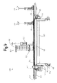
- the pressing assembly 40 is pivotally mounted to the frame member 42 (the pivot axis S extends in the y-direction).
- a tilting assembly 43 is provided with a lifting cylinder 44, with which various tilting positions can be reached.
- the lifting cylinder and a lifting spindle could be used.
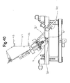
- Two different tilt positions are shown in the following figures 9 and 10. Simpler devices 1 usually do not need such tilt arrangements. In the simpler embodiments, the pressing arrangement would be fixedly connected to the carrier parts.
- the entire device 1 is movable on longitudinal rails 46 in the x-direction, ie in a working surface longitudinal direction.
- a motor 47 for this purpose for the drive can be seen in Fig. 6.
- a gear transmission can be used for this longitudinal displacement.
- Such longitudinal rails can be laid over an entire hall length. In larger warehouses thus several adjacent layer composite elements can be made.
- a gear transmission can be seen, it consists essentially of a in the x-direction extending rack 49 and a meshing with this gear 48th
- the gear transmission arrangement for the lifting-lowering movement of the pressing assembly 40 is further recognizable.
- This consists essentially of z-direction extending racks 81 and associated gears 82.
- the two sides are connected to each other for transmission of power through the shaft 47.
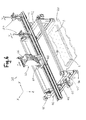
- FIGS. 8 to 10 show side views of the dowel unit 60 in different positions. Further details of the dowel unit 60 can be seen in FIGS. 12 to 14. Such a dowel unit (FIGS. 12 to 14) could also be used in conventional devices for the production of layered composite elements (in particular without a press arrangement 40). Furthermore, attached to the pressing assembly elements 76 ', 76 "and 76' '' recognizable, which serve to define a respective end position (reference of the axis of rotation or pivot axis).
- the dowel unit 60 has a dowel magazine 66, in which dowels can be inserted from above in a horizontal position.
- the dowel magazine 66 is laterally closed by a Rüttelplatte 67.
- By shaking or vibrating the vibrating plate by means of an upper and lower vibrating cylinder 68 the dowels can be separated more easily. Of course, could also satisfy a single vibrating cylinder.
- the dowels are finally singulated by means of a revolver 70 that can be driven by a motor and are deposited by a dropping motion in the dowel shaft 73 onto a set-up lever 71 arranged obliquely in the rest position (FIG. 14, FIG. 13 shows the dowel shaft closed, in FIG the dowel shaft - for information purposes - partially open).
- the pneumatically activatable raising lever 71 is then brought by a pivoting movement in a dowel position.
- the dowel can then be used in dowel direction (in non-tilted pressing arrangements: in the z direction) on the plunger 61 in a corresponding hole.
- the Insertion movement takes place with the aid of an electrically drivable spindle 72.
- Pneumatic or hydraulic systems could also be used for the insertion movement.
- the insertion movement can be controlled via a CNC axis.
- an electric motor 53 is further seen, with which the dowel unit 60 on the pressing arrangement is displaced back and forth.
- FIGS. 12 to 14 a compression device 62 and an applicator device 63 can be seen, by means of which a dowel is carried out during the pushing movement of the ram.
- These components are obviously mounted below the carriage 75 at this and arranged relative to the press beams between them. The exact operation of these components will be explained in detail with reference to FIGS. 15 to 22.
- FIG. 15 shows a method for compacting a dowel 9.
- the dowel is thereby acted upon by a total of four press rollers 28a, 28b, 28c, 28d, whose axes of rotation extend at right angles to the longitudinal center axis of the dowel 9.
- the roller end faces designated 29 are formed convexly curved, wherein the curvature corresponds approximately to the dowel radius.
- ribs 30 are also arranged, which cause parallel grooves on the dowel surface.
- the press rollers are biased against the center of the plug and rotate in the same direction, so that a dowel is passed through the roller quartet and thereby compressed.
- the dowel is unrolled between the press rolls and compacted by a few tenths of a millimeter.
- FIG. 16 shows a compression device 62 according to the method according to FIG. 15, in which the pressure rollers 28 are arranged in a cross-sectional configuration in plan view. Furthermore, fasteners 65 can be seen here, in which the press rollers 28 are freely rotatably mounted. The fastening elements 65 have bores for receiving fastening screws for fastening in the dowel unit. They also serve to secure an applicator (not shown) (see, in particular, the following Fig. 20).
- FIG. 17 shows a method for the surface coating of a plug for the application of a fluid.
- the dowel is not sprayed (see Fig. 5 or Fig. 22), but coated with a liquid film.
- the applicator 63 consists of an insertion plate 31, which has an insertion opening 32 for the dowel 9.
- a channel plate 33 is pressed against the insertion plate 31 in such a way that an annular gap 37 surrounding the insertion opening 32 remains.
- This annular gap opens out into an annular channel 34, which is sealed by means of a seal 35.
- Via a supply channel 36 the fluid can be fed into the annular channel 34, which is pressed from there as a film against the insertion opening 32.
- the applicator 63 has a disc-shaped configuration.
- the fastening holes which can be seen further in FIG. 18 serve for fastening the application device to the compression device (compare FIG. 20).
- FIG. An assembly of the compression device 62 and the applicator 63 is shown in FIG. It can be seen that, with this arrangement, dowels can be compacted directly one after the other and then charged (or coated) with the fluid.
- the dowels may also be compacted in other ways before being inserted.
- a dowel 9 lies in the gusset between two bearing rollers 25 and 25 'and is acted upon by a driven press roller 26. It would also be conceivable that all press rolls are driven.
- the rollers could be conical or thread-like, whereby an advance of the dowel in the z-direction would be achievable (not shown).
- a plug 9 for supplying the fluid can be guided through an annular nozzle 27, where it is sprayed with liquid adhesive 21.
- the dowel is inserted into the borehole 19 whose diameter is matched to the compacted dowel in such a way that the dowel braces when re-expanded in the borehole.
- FIG. 22 shows a side view of an embossing roll 10 with which the depressions shown in FIG. 2 can be attached to the individual boards 17.
- the embossing roll consists of a multiplicity of embossing wheels 12 to 15, which are provided with individual teeth and which rest on a shaft 11.
- the teeth of the individual wheels are each offset from one another. Width, configuration and penetration depth of each tooth can vary depending on the purpose.
- the stamping of the hollows simultaneously causes a compaction and a partial breakage of wood fibers.
- the embossing of the depressions is coordinated with the purpose of use on a continuous machine, similar to a thicknessing machine.
- the individual woods are processed on one side, optionally on two sides.
- the partial severing of the fibers has the advantage that they can not straighten up again in the event of moisture absorption.
- the woods are stacked in layers on a work surface 20. Shown here is a first blank layer 22, on which a second blank layer 23 is to be stored.
- a liquid or pasty adhesive for example molasses
- the woods of the second blank layer 23 are deposited on the first blank layer 22, wherein, evidently, the adhesive 21 is at least partially distributed to a thin film.
Landscapes
- Engineering & Computer Science (AREA)
- Life Sciences & Earth Sciences (AREA)
- Wood Science & Technology (AREA)
- Mechanical Engineering (AREA)
- Forests & Forestry (AREA)
- Architecture (AREA)
- Manufacturing & Machinery (AREA)
- Civil Engineering (AREA)
- Structural Engineering (AREA)
- Laminated Bodies (AREA)
- Inorganic Insulating Materials (AREA)
- Inorganic Compounds Of Heavy Metals (AREA)
- Rod-Shaped Construction Members (AREA)
- Veneer Processing And Manufacture Of Plywood (AREA)
Abstract
Description
Die Erfindung betrifft ein Verfahren und eine Vorrichtung zum Herstellen eines Schichtverbundelements. Ein Schichtverbundelement besteht im Wesentlichen aus mehreren Lagen von miteinander verbundenen Bauelementen. Derartige Schichtverbundelemente werden in der Praxis vorzugsweise als Wand-, Decken- oder Dachelemente für Gebäude eingesetzt. Dabei hat sich gezeigt, dass Bauelemente aus nachwachsenden Rohstoffen, insbesondere Hölzer, besonders als Bauelemente geeignet sind. Vorteilhafte Ausführungen von Schichtverbundelementen weisen wenigstens zwei benachbarte Lagen mit Hölzern unterschiedlicher Richtungen auf. Zur Verbindung der Lagen sind die Hölzer mit Dübeln durchsetzt.The invention relates to a method and an apparatus for producing a layer composite element. A layer composite element consists essentially of several layers of interconnected components. Such layer composite elements are preferably used in practice as wall, ceiling or roof elements for buildings. It has been shown that components made of renewable raw materials, especially woods, are particularly suitable as components. Advantageous embodiments of layer composite elements have at least two adjacent layers with woods of different directions. To connect the layers, the woods are interspersed with dowels.
Ein vergleichbares Schichtverbundelement ist aus der
Es ist deshalb eine Aufgabe der vorliegenden Erfindung, die Nachteile des Bekannten zu vermeiden, insbesondere also ein Verfahren zum Herstellen eines Schichtverbundelements zu schaffen, das einfach handhabbar ist. Das Verfahren soll weiter eine hohe Prozesssicherheit gewährleisten.It is therefore an object of the present invention to avoid the disadvantages of the known, in particular therefore to provide a method for producing a layer composite element which is easy to handle. The process should also ensure high process reliability.
Diese Aufgaben werden mit einem Verfahren mit den Merkmalen im Anspruch 1 gelöst. Durch die Aufrechterhaltung der Pressung der Lagen beim Bohrvorgang und beim Einsetzen des Dübels wird erreicht, dass eine präzise Positionierung der Dübel sichergestellt ist bzw. bleibt. Fehlstellungen von Bauelementen können so ausgeschlossen werden. Als Bauelemente kommen insbesondere Hölzer, andere nachwachsende Rohstoffe wie Bambus, oder cellulosehaltige oder holzartige Werkstoffe in Frage. Denkbar wären aber auch beispielsweise Bauelemente aus Faserverbundwerkstoffen, Kunststoffen oder anderen geeigneten Materialien. Aus ökologischen Gründen ist es besonders vorteilhaft, wenn Dübel aus Holz verwendet werden. Dabei sind Dübel aus einem Hartholz besonders geeignet.These objects are achieved by a method having the features in claim 1. By maintaining the pressure of the layers during the drilling process and the insertion of the dowel is achieved that a precise positioning of the dowels is ensured or remains. Malpositions of components can be excluded. As components are in particular woods, other renewable resources such as bamboo, or cellulose-containing or wood-like materials in question. Conceivable, however, would be, for example, components made of fiber composites, plastics or other suitable materials. For ecological reasons, it is particularly advantageous if dowels made of wood are used. Dowels made of hardwood are particularly suitable.
Die vorgenannten Arbeitsschritte, insbesondere der Bohrvorgang und das Einsetzen des Dübels, erfolgen bevorzugt von oben nach unten (bzw. in vertikaler Richtung). Selbstverständlich wäre es aber auch vorstellbar, diese Arbeitschritte in umgekehrter Richtung auszuführen. So wäre es beispielsweise bei einem Bohrvorgang von unten nach oben möglich, dass die entstehenden Späne auf besonders einfache Art und Weise unter Ausnutzung der Schwerkraft aus dem Bohrloch wegführbar wären.The aforementioned steps, in particular the drilling process and the insertion of the anchor, are preferably carried out from top to bottom (or in the vertical direction). Of course, it would also be conceivable to carry out these steps in the opposite direction. So it would be possible, for example, in a drilling process from bottom to top that the resulting chips would be wegführbar in a particularly simple manner by utilizing gravity from the wellbore.
Vorteilhaft kann es sein, wenn vor dem Einsetzen des Dübels in das Bohrloch der Dübel im Durchmesser mechanisch verdichtet wird. Ein derart komprimierter Dübel kann somit auf einfache Art und Weise in das Bohrloch eingesetzt werden. Bedingt durch das Rückstellvermögen - insbesondere bei der Verwendung von Holzdübeln - quillt das Material im Bohrloch wieder auf und verspannt sich kraftschlüssig. Durch geeignete Wahl der Verdichtungsparameter kann ein gewünschter Kraftschluss auf einfache Art und Weise eingestellt werden. Die Verdichtung kann mittels Kompressionseinrichtungen auf verschiedene Arten erfolgen. Beispielsweise kann der Dübel zwischen Rollen oder Walzen (Presswalzen) hindurchgeführt werden, wodurch eine mechanische Verdichtung im Durchmesser erreichbar ist. Der Dübel könnte aber auch durch eine Matrize gestossen werden.It can be advantageous if, prior to the insertion of the anchor into the drilled hole, the anchor is mechanically compressed in diameter. Such a compressed dowel can thus be easily inserted into the wellbore. Due to the resilience - especially when using wooden dowels - the material swells in the borehole again and tightens frictionally. By a suitable choice of the compression parameters, a desired adhesion can be adjusted in a simple manner. The compression can be done by means of compression devices in various ways. For example The dowel can be passed between rollers or rollers (press rollers), whereby a mechanical compression in diameter can be achieved. The dowel could also be pushed through a die.
Die Dübel können beim Verdichtungsvorgang zusätzlich mit einer Profilierung versehen werden.The dowels can be additionally provided with a profiling during the compression process.
Besonders vorteilhaft kann es sein, wenn der Dübel vor dem Einsetzen in das Bohrloch mit einem Fluidum beaufschlagt wird. Als Fluidum kann beispielsweise ein Gleitmittel eingesetzt werden, das wegen der Reduktion der Reibung beim Einpressen die Einführung der Dübel erleichtert. Weiter kann so eine Schubverformung reduziert werden. Als Fluidum besonders geeignet ist dabei Wasser. Das Wasser oder ein anderes Quellmittel könnten zusätzlich mit verschiedenen Zusatzstoffen versehen sein kann. Als Zusatzstoffe könnten beispielsweise Haftmittel, und/oder Gleitmittel verwendet werden. Auch Lösungsmittel (anstatt Wasser) wie beispielsweise Ameisensäure zum Anlösen eines Holzdübels wären vorstellbar. Das Fluidum kann Haftmittel enthalten, die die Verbindungswirkung der Dübel und insbesondere deren Auszugswerte weiter erhöhen können. Als Haftmittel kommen beispielsweise Leime, auf natürlichen Stoffen basierende Haftmittel wie Harz, Melasse, Stärke, Kasein, Gluten etc. in Betracht. Auch eine Verleimung mit holzeigenem Lignin ist vorstellbar.It may be particularly advantageous if the plug is subjected to a fluid prior to insertion into the borehole. As a fluid, for example, a lubricant can be used, which facilitates the introduction of dowels due to the reduction of friction during insertion. Further, such a shear deformation can be reduced. As a fluid is particularly suitable water. The water or other swelling agent could additionally be provided with various additives. As additives, for example, adhesives, and / or lubricants could be used. Also solvents (instead of water) such as formic acid for dissolving a wooden dowel would be conceivable. The fluid may contain adhesives which may further increase the bonding effect of the dowels and, in particular, their pull-out values. Suitable adhesives are, for example, glues, adhesives based on natural substances, such as resin, molasses, starch, casein, gluten, etc. It is also conceivable to glue it with woody lignin.
Die Beaufschlagung der Dübel mit dem Fluidum kann vor oder gleichzeitig mit dem Verdichtungsvorgang erfolgen. Vorteile können sich jedoch insbesondere ergeben, wenn der Dübel unmittelbar nach dem Verdichtungsvorgang beaufschlagt wird.The loading of the dowels with the fluid can take place before or simultaneously with the compression process. However, advantages may arise, in particular, if the plug is acted upon immediately after the compacting process.
Der Verdichtungsvorgang und die Beaufschlagung des Dübels mit dem Fluidum kann auf vorteilhafte Art und Weise mit dem Vorgang des Einsetzens des Dübels in das Bohrloch kombiniert werden. Wenn ein Dübel mittels eines Stössels durch einen Stossvorgang in das Bohrloch eingesetzt wird, so kann bei diesem Stossvorgang der Dübel verdichtet und/oder mit dem Fluidum beaufschlagt werden.The compaction process and the loading of the plug with the fluid can advantageously with the process the insertion of the dowel into the borehole. If a dowel is inserted by means of a plunger by a collision process in the borehole, it can be compressed in this collision process of the dowel and / or acted upon by the fluid.
Das Verfahren lässt sich besonders effizient betreiben, wenn jeweils eine Gruppe von wenigstens zwei Bohrlöchern gebohrt und Dübel in die Bohrlöcher eingesetzt werden, wobei je Gruppe die Pressung aufrecht erhalten wird.The process can be operated particularly efficiently if in each case a group of at least two boreholes are drilled and dowels are inserted into the boreholes, the pressure being maintained per group.
Vorteilhaft kann es sein, wenn der Pressvorgang mittels einer Pressanordnung durchgeführt wird, die zum sequentiellen Pressen von einer Gruppe zur nächsten Gruppe bewegt wird. Die Produktivität kann durch diesen Verfahrensablauf weiter verbessert werden.It can be advantageous if the pressing operation is carried out by means of a pressing arrangement which is moved from one group to the next group for sequential pressing. The productivity can be further improved by this process.
Je nach Bedürfnis können für das Verfahren verschiedenartig gebildete Gruppen gewählt werden. So könnte beispielsweise eine Gruppe durch clusterartig verteilte Verbindungsstellen gebildet sein. Vorteilhaft ist es jedoch, wenn die Gruppen durch quer zu einer Arbeitsflächen-Längsrichtung verlaufende, nebeneinander angeordnete Reihen von Verbindungsstellen gebildet sind. Durch eine solche reihenweise Ausgestaltung der Verfahrensschritte vereinfacht sich der Verfahrensablauf zum Herstellen insbesondere von sich auf der Arbeitsfläche in Längsrichtung erstreckenden Schichtverbundelementen wesentlich. Quer bzw. Querrichtung bedeutet hier eine Richtung auf der Arbeitsfläche, die zur Längsrichtung einen Winkel bildet. Besonders bevorzugt verläuft die Querrichtung im rechten Winkel zur Längsrichtung. Eine Reihe kann als Linie betrachtet werden, auf welcher Verbindungsstellen angeordnet sind.Depending on the need, various groups formed for the process can be selected. For example, a group could be formed by cluster-like distributed joints. It is advantageous, however, if the groups are formed by rows of connecting points running transversely to a working surface longitudinal direction. By means of such a row-by-row configuration of the method steps, the method sequence for producing, in particular, layer composite elements extending in the longitudinal direction on the work surface is substantially simplified. Transverse or transverse direction here means a direction on the work surface, which forms an angle to the longitudinal direction. Particularly preferably, the transverse direction runs at right angles to the longitudinal direction. A row can be considered as a line on which joints are arranged.
Zum Erzeugen von reihenweisen Verbindungsstellen können die ausgelegten Lagen mit Hilfe einer sich quer zur Arbeitsflächen-Längsrichtung erstreckenden Pressanordnung zusammengepresst werden, unter Aufrechterhaltung der Pressung in die Reihe Bohrlöcher gebohrt und Dübel eingesetzt werden. Die Pressung kann dann aufgelöst werden. Danach kann die Pressanordnung zur nachfolgenden Reihe verschoben werden und die vorgenannten Bearbeitungsschritte (Pressen, Bohren, Dübel einsetzen) können wiederholt werden.To create row-wise joints, the laid-up sheets may be pressed together by means of a press arrangement extending transversely to the work surface longitudinal direction, boring holes and using dowels while maintaining the pressure in the row. The squeeze can then be dissolved. Thereafter, the pressing arrangement can be moved to the next row and the aforementioned processing steps (pressing, drilling, dowel insert) can be repeated.
Ein Bohrloch kann durchgehend durch die Lagen gebohrt werden (Durchgangsloch). Als Bohrloch kann aber auch ein Sackloch gebohrt werden, wodurch die Dübel eine aussen liegende Lage nur teilweise durchdringen. Dies hat einerseits den Vorteil, dass auf diese Weise eine optisch hochwertige Gutseite am Schichtverbundelement gewonnen wird. Anderseits kann auf diese Weise auch die Arbeitsfläche geschont werden, da bei Durchgangslöchern ein Eingriff durch Anbohren der Arbeitsfläche unvermeidbar wäre. Auswechselbare Verschleissplatten zur Bildung der Arbeitsfläche wären somit unnötig.A borehole can be drilled through the layers continuously (through hole). However, a blind hole can also be drilled as a drill hole, as a result of which the dowels only partially penetrate an outer layer. On the one hand, this has the advantage that in this way an optically high-quality good side is obtained on the layer composite element. On the other hand, the working surface can be spared in this way, since at through holes engagement by drilling the work surface would be unavoidable. Replaceable wear plates to form the work surface would thus be unnecessary.
Wenigstens eine Reihe kann mit schräg verlaufenden Dübeln versehen sein. Auf diese Weise wird ein zusätzlicher Formschluss erreicht. Besonders vorteilhaft ist es, wenn in wenigstens zwei benachbarten Reihen Dübel mit unterschiedlichen Richtungen eingesetzt werden.At least one row can be provided with oblique dowels. In this way, an additional positive locking is achieved. It is particularly advantageous if dowels with different directions are used in at least two adjacent rows.
Der Pressdruck sollte vorzugsweise gleichmässig über die gesamte sich in Querrichtung erstreckende Breite des Schichtverbundelements verteilt sein. Für eine gleichmässige Kraftverteilung können hierzu auf der Pressanordnung angeordnete Kompensationsmittel dienen. Als Kompensationsmittel zum Ausgleich unterschiedlicher Höhen der Lagen über die Breite könnten beispielsweise Kissen oder Schläuche (z.B. Gummischläuche) verwendet werden, die sich auf der Pressanordnung in Querrichtung erstrecken.The pressing pressure should preferably be distributed uniformly over the entire width of the layer composite element extending in the transverse direction. For a uniform force distribution, compensating means arranged on the pressing arrangement can serve for this purpose. Cushions, for example, could serve as compensating means for compensating for different heights of the layers across the width or hoses (eg, rubber hoses) extending transversely on the press assembly.
Ein weiterer Aspekt der Erfindung betrifft eine Vorrichtung zum Herstellen eines Schichtverbundelements, insbesondere eine Vorrichtung zur Durchführung des oben beschriebenen Verfahrens. Die Vorrichtung weist zum Zusammenpressen der Lagen gegen eine Arbeitsfläche eine Pressanordnung auf, mit welcher die gesamte Breite des Schichtverbundelements einem Pressdruck unterwerfbar ist, wobei sich die Pressanordnung vorzugsweise quer zur Arbeitsflächen-Längsrichtung erstreckt. Weiterhin weist die Vorrichtung wenigstens eine Bohreinheit mit einem Bohrkopf zum Bohren von Bohrlöchern sowie wenigstens eine Dübeleinheit mit einem Stössel zum Einsetzen von Dübeln in die Bohrlöcher auf. Die Breite ist dabei vorzugsweise durch eine rechtwinklig zur Längsrichtung verlaufende Querrichtung vorgegeben.Another aspect of the invention relates to a device for producing a layer composite element, in particular a device for carrying out the method described above. The device has a pressing arrangement for compressing the layers against a working surface, with which the entire width of the layer composite element can be subjected to a pressing pressure, wherein the pressing arrangement preferably extends transversely to the working surface longitudinal direction. Furthermore, the device has at least one drilling unit with a drill head for drilling boreholes and at least one dowel unit with a plunger for inserting dowels into the boreholes. The width is preferably predetermined by a transverse direction perpendicular to the longitudinal direction.
Die Bohreinheit und/oder die Dübeleinheit können vorzugsweise in Querrichtung verschiebbar auf der Pressanordnung angeordnet sein. Auf diese Weise können Bohreinheit und/oder Dübeleinheit zur Pressanordnung einfach positioniert werden.The drilling unit and / or the dowel unit may preferably be arranged displaceably on the press arrangement in the transverse direction. In this way, drilling unit and / or dowel unit for pressing arrangement can be easily positioned.
Die Pressanordnung kann mittels eines Verschiebemechanismus in der Arbeitsflächen-Längsrichtung verschiebbar sein. Die Führung der Pressanordnung kann auf in Längsrichtung verlaufenden Längsschienen erfolgen. Eine solche Anordnung gewährleistet, dass auch vergleichsweise grosse Schichtverbundelemente oder mehrere nebeneinander liegende Schichtverbundelemente mit der gleichen Vorrichtung bearbeitet bzw. hergestellt werden können.The pressing assembly may be slidable by means of a sliding mechanism in the working surface longitudinal direction. The leadership of the press assembly can be done on longitudinally extending longitudinal rails. Such an arrangement ensures that even comparatively large layer composite elements or a plurality of adjacent layer composite elements can be processed or produced with the same device.
Die Dübeleinheit kann derart verschiebbar auf der Pressanordnung angeordnet sein, dass das Dübelaggregat über eine zuvor von der Bohreinheit erzeugtes Bohrloch verschiebbar ist.The dowel unit may be slidably mounted on the press assembly such that the dowel assembly is slidable over a borehole previously created by the drilling unit.
Die Dübeleinheit kann eine Kompressionseinrichtung zum mechanischen Verdichten der Dübel im Durchmesser aufweisen. Vorzugsweise ist dabei die Dübeleinheit derart ausgestaltet, dass der Stössel durch die Kompressionseinrichtung durchführbar ist, wodurch der Kompressions- bzw. Verdichtungsvorgang auf einfache Art und Weise in den Verdübelungsvorgang integriert werden kann.The dowel unit may have a compression device for mechanically compressing the dowels in diameter. Preferably, the dowel unit is designed such that the plunger can be performed by the compression device, whereby the compression or compression process can be integrated in a simple manner in the doweling process.
Die Kompressionseinrichtung kann wenigstens zwei Presswalzen aufweisen, deren Drehachsen rechtwinklig (oder eventuell auch schräg) zur Dübelrichtung verlaufen (können), wobei die Dübel zwischen Presswalzen hindurchführbar sind. Vorzugsweise werden jedoch drei oder besonders bevorzugt vier Presswalzen verwendet. Im Falle der vier Presswalzen stehen jeweils zwei Presswalzen einander gegenüber, die in der Draufsicht eine rechtwinklige Kreuzkonfiguration ausbilden.The compression device may have at least two press rollers whose axes of rotation extend at right angles (or possibly also obliquely) to the dowel direction, wherein the dowels can be guided between press rollers. Preferably, however, three or more preferably four nip rolls are used. In the case of the four press rolls, two press rolls face each other, which form a right-angled cross-configuration in plan view.
Die Presswalzen können Walzenstirnseiten aufweisen, die korrespondierend zu den verwendeten Dübeln konvex gekrümmt ausgebildet sind. Die Krümmung entspricht also vorzugsweise dem Dübelradius. Auf den Walzenstirnseiten bzw. Mantelflächen der Presswalzen können Rippen angeordnet sein, welche an der Dübeloberfläche Rillen verursachen. Die Rippen können parallel auf der Walzenstirnseite angeordnet sein. Selbstverständlich sind je nach gewünschter Profilierung auf den Dübeloberflächen auch andere Rippengestaltungen vorstellbar.The press rollers may have roller end faces which are designed to be convexly curved corresponding to the dowels used. The curvature thus preferably corresponds to the dowel radius. On the roll end faces or lateral surfaces of the press rolls ribs can be arranged, which cause grooves on the dowel surface. The ribs can be arranged in parallel on the roller front side. Of course, depending on the desired profiling on the dowel surfaces and other rib designs are conceivable.
Die Dübeleinheit kann eine Auftrageinrichtung zum Beaufschlagen der Dübel mit einem Fluidum aufweisen. Das Fluidum kann eine flüssige oder pastöse Form haben. Je nach Anwendungszweck kann das Fluidum ein Gleitmittel und/oder Haftmittel sein.The dowel unit may have an application device for applying a fluid to the dowels. The fluid may have a liquid or pasty form. Depending on the application, the fluid may be a lubricant and / or adhesive.
Die Auftrageinrichtung kann Sprühdüsen enthalten, die vorzugsweise auf einem Ring angeordnet sind. Durch die ringförmige Anordnung der Sprühdüsen kann die gesamte Oberfläche der Dübel besonders einfach besprüht werden. Hervorragende Auftragresultate ergibt ein scheibenförmiges Auftragelement (als Auftrageinrichtung) mit einer Einführöffnung zum Hindurchführen der Dübel. In der Einführöffnung ist wenigstens ein diese umgebender Ringspalt angeordnet, in welchen das Fluidum einspeisbar ist. Über eine Steuereinrichtung ist der Einspeisevorgang derart ansteuerbar, dass nur beim Hindurchführen des Dübels durch die Auftrageinrichtung Fluidum eingespeist wird. Auf diese Weise wird ein unnötiges Beaufschlagen (wenigstens der obersten Lage) der Bauelemente vermieden.The applicator may include spray nozzles, which are preferably arranged on a ring. By the annular arrangement The spray nozzles, the entire surface of the dowels can be sprayed very easily. Excellent order results results in a disk-shaped application element (as an application device) with an insertion opening for passing the dowels. At least one surrounding annular gap, in which the fluid can be fed in, is arranged in the insertion opening. Via a control device of the feed operation is controlled such that only when passing the anchor through the applicator fluid is fed. In this way, an unnecessary application (at least the uppermost layer) of the components is avoided.
Vorteilhaft kann es sein, wenn die Auftrageinrichtung bezogen auf die Dübelrichtung unterhalb der Kompressionseinrichtung angeordnet ist. In einer bevorzugten Ausführungsform kann die Pressanordnung wenigstens einen gegen die Arbeitsfläche verschiebbar gelagerten Pressbalken aufweisen. Dieser Pressbalken erstreckt sich somit quer zur Arbeitsflächen-Längsrichtung.It can be advantageous if the application device is arranged below the compression device in relation to the dowel direction. In a preferred embodiment, the pressing arrangement can have at least one pressing beam displaceably mounted against the working surface. This press beam thus extends transversely to the work surface longitudinal direction.
Besonders vorteilhaft kann es sein, wenn die Pressanordnung zwei parallele und in einem Abstand zueinander verlaufende Pressbalken aufweist, wobei zwischen den Pressbalken ein Bohrkopf einer Bohreinheit und/oder ein Stössel einer Dübeleinheit durchführbar sind. Eine solche Anordnung gewährleistet eine besonders günstige Verteilung des Pressdrucks während dem Bohr- und/oder Verdübelungsvorgang.It may be particularly advantageous if the pressing arrangement comprises two parallel and spaced-apart pressing beams, wherein between the pressing bars a drill head of a drilling unit and / or a plunger of a dowel unit can be carried out. Such an arrangement ensures a particularly favorable distribution of the pressing pressure during the drilling and / or doweling process.
Der Pressbalken kann auf beiden Seiten in einer Lageranordnung gelagert sein, wodurch gewährleistet ist, dass beide Enden des Pressbalkens gleichzeitig zum Verschieben heb- und senkbar sind.The pressing beam can be mounted on both sides in a bearing arrangement, whereby it is ensured that both ends of the pressing beam can be simultaneously raised and lowered for movement.
Am Pressbalken kann jeweils zur Schonung der obersten Lage des Schichtverbundelements ein Anschlagelement aus Holz oder einem anderen Material angeordnet sein. Für eine gleichmässige Kraftverteilung und/oder zum Ausgleich unterschiedlicher Höhen der Lagen können hierzu auf dem Pressbalken auch Kompensationsmittel angeordnet sein. Kompensationsmittel könnten beispielsweise Kissen, Profile aus elastischem Material oder Schläuche (z.B. mit Luft gefüllte Gummischläuche) über die Breite sein, die sich auf der Pressanordnung in Querrichtung erstrecken.At the press beam, in each case to protect the uppermost layer of the layer composite element, a stop element made of wood or a be arranged other material. For a uniform distribution of force and / or to compensate for different heights of the layers can also be arranged on the press beam compensation means. Compensating means could be, for example, cushions, elastic material profiles, or hoses (eg, air filled rubber hoses) across the width extending transversely on the pressing assembly.
Zum Erzeugen von schräg verlaufenden Dübeln kann eine Kippanordnung vorgesehen sein, mit welcher die Pressanordnung in eine Schräglage zur Arbeitfläche verstellbar ist. Selbstverständlich wäre es auch vorstellbar, in einer Kipplage voreingestellte Bohreinheiten und/oder Dübeleinheiten auf der Pressanordnung vorzusehen.For generating oblique plugs, a tilting arrangement can be provided, with which the pressing arrangement is adjustable in an inclined position to the working surface. Of course, it would also be conceivable to provide pre-set drilling units and / or dowel units on the pressing arrangement in a tilted position.
Die Bohreinheit und die Dübeleinheit können unabhängig voneinander auf der Pressanordnung verschiebbar ausgebildet sein. Dank dieser Anordnung ist die Möglichkeit einer flexiblen Gestaltung der Bearbeitungsvorgänge gegeben.The drilling unit and the dowel unit can be designed to be displaceable independently of one another on the pressing arrangement. Thanks to this arrangement, the possibility of flexible design of the machining operations is given.
Eine solche Dübeleinheit könnte auch für sich allein Gegenstand einer Erfindung bilden. Eine Kombination mit der beschriebenen Pressanordnung ist nicht zwingend erforderlich.Such a dowel unit could also form the subject of an invention on its own. A combination with the described pressing arrangement is not absolutely necessary.
Der Verschiebemechanismus zum Verschieben der Pressanordnung in Längsrichtung, zum Verschieben der Pressbalken gegen die Arbeitsfläche, zum Verschieben der Bohreinheit auf der Pressanordnung und/oder zum Verschieben der Dübeleinheit auf der Pressanordnung in Querrichtung kann jeweils ein Zahnradgetriebe sein. Das Zahnradgetriebe besteht im Wesentlichen aus einem in Verschieberichtung verlaufenden Zahnkranz und einem Zahnrad, das mit diesem in Eingriff steht. Der Antrieb des Zahnrads kann dabei jeweils über einen Elektromotor erfolgen. Selbstverständlich wäre es aber auch denkbar, beispielsweise hydraulische Hubzylinder oder andere Antriebe zu verwenden. Die einzelnen Verschiebemechanismen sind dabei vorteilhaft selbstfahrend auszugestalten.The sliding mechanism for displacing the pressing assembly in the longitudinal direction, for displacing the pressing beams against the working surface, for displacing the drilling unit on the pressing arrangement and / or for displacing the dowel unit on the pressing arrangement in the transverse direction can each be a gear transmission. The gear transmission consists essentially of a running in the direction of gear sprocket and a gear which is engaged with this. The drive of the gear can be done in each case via an electric motor. Of course but it would also be possible to use, for example, hydraulic lifting cylinders or other drives. The individual displacement mechanisms are advantageous to design self-propelled.
Die Antriebe für die genannten Verschiebemechanismen können vorteilhaft auf der Pressanordnung angeordnet werden, wodurch die Pressanordnung autark ausgebildet wäre. Vorteilhaft kann es auch sein, wenn beispielsweise ein Tank für das Fluidum der Pressanordnung zugeordnet ist. Auf diese Weise könnte die Vorrichtung im Wesentlichen autark betrieben werden.The drives for the said displacement mechanisms can be advantageously arranged on the pressing arrangement, whereby the pressing arrangement would be self-sufficient. It can also be advantageous if, for example, a tank for the fluid is assigned to the press arrangement. In this way, the device could be operated essentially independently.
Die Dübeleinheit kann weiterhin ein Dübelmagazin zur Aufnahme einer Vielzahl von Dübeln aufweisen. Die Dübel können im Dübelmagazin in waagrechter Lage aufbewahrbar sein, wodurch der Einfüllvorgang vereinfacht werden kann. Über eine Rüttelanordnung können die im Dübelmagazin aufbewahrten Dübel vereinzelt werden. Mittels eines pneumatisch aktivierbaren Aufrichthebels kann ein vereinzelter, sich noch in waagrechter Lage befindlicher Dübel in eine gewünschte Dübelrichtung gebracht werden.The dowel unit may further comprise a dowel magazine for receiving a plurality of dowels. The dowels can be stored in the dowel magazine in a horizontal position, whereby the filling process can be simplified. About a Rüttelanordnung the dowels stored in the dowel magazine can be separated. By means of a pneumatically activated Aufrichthebels an isolated, still located in a horizontal position dowel can be brought in a desired Dübelrichtung.
Beidseitig an der Pressanordnung, insbesondere beidseits am Pressbalken, können zum Heben und Senken Hubspindeln (statt einem Zahnradgetriebe) auch angeordnet sein, wobei die Kraft von einer Seite zur andern über eine Welle übertragbar ist.On both sides of the pressing arrangement, in particular on both sides of the pressing beam, lifting spindles (instead of a gear transmission) can also be arranged for lifting and lowering, wherein the force can be transmitted from one side to the other via a shaft.
Die vorgängig beschriebene Dübeleinheit kann auch für sich alleine für die Herstellung von Schichtverbundelementen Vorteile gegenüber bekannten Vorrichtungen zur Herstellung von Schichtverbundelementen aufweisen. Eine Kombination mit einer erfindungsgemässen Pressanordnung ist deshalb nicht unbedingt erforderlich.The dowel unit described above can also have advantages over known devices for the production of layer composite elements on their own for the production of layer composite elements. A combination with a press arrangement according to the invention is therefore not absolutely necessary.
Weitere Einzelmerkmale und Vorteile der Erfindung ergeben sich aus der nachfolgenden Beschreibung eines Ausführungsbeispiels und aus den Zeichnungen. Es zeigen:
- Figur 1
- eine perspektivische Darstellung eines Schichtverbundelements mit freigelegten Schichten,
Figur 2- einen Querschnitt durch ein Schichtverbundelement mit unterschiedlich eingesetzten Dübeln,
Figur 3- eine schematische Darstellung einer Pressanordnung zum Zusammenpressen von Lagen eines Schichtverbundelements,
Figur 4- eine schematische Darstellung des Bohrvorgangs unter Aufrechterhaltung der Pressung,
Figur 5- eine schematische Darstellung des Einsetzen eines Dübels unter Aufrechterhaltung der Pressung,
Figur 6- eine perspektivische Darstellung einer erfindungsgemässen Vorrichtung zum Herstellen eines Schichtverbundelements,
Figur 7- eine Seitenansicht der Vorrichtung gemäss Fig. 6 mit einer Dübeleinheit,
Figur 8- eine Vorderansicht der Vorrichtung gemäss Fig. 6 mit einer Dübeleinheit und zwei Bohreinheiten
Figur 9- die Vorrichtung gemäss Fig. 7 mit einer gekippten Dübeleinheit in einer ersten Kippstellung,
Figur 10- die Vorrichtung gemäss Fig. 7 mit einer Dübeleinheit in einer zweiten Kippstellung,
Figur 11- eine perspektivische Darstellung einer Bohreinheit,
Figur 12- eine perspektivische Darstellung einer Dübeleinheit aus einem ersten Betrachtungswinkel,
Figur 13- die Dübeleinheit gemäss Fig. 12 aus einem zweiten Betrachtungswinkel",
Figur 14- die Dübeleinheit gemäss Fig. 12 aus einem dritten Betrachtungswinkel,
Figur 15- eine schematische Darstellung einer Methode zur Verdichtung eines Dübels,
Figur 16- eine perspektivische Darstellung einer Kompressionseinrichtung zur Durchführung der Methode gemäss Fig. 15,
Figur 17- eine Darstellung einer Auftrageinrichtung zur Beaufschlagung eines Dübels mit einem Fluidum (Schnitt A-A gemäss Fig. 18),
Figur 18- eine perspektivische Darstellung der Auftrageinrichtung gemäss Fig. 17,
Figur 19- ein Zusammenbau der Kompressionseinrichtung gemäss Fig. 16 und der Auftrageinrichtung gemäss Fig. 17 im Querschnitt,
Figur 20- die schematische Darstellung eines Dübels beim Verdichten gemäss einer alternativen Methode,
Figur 21- die schematische Darstellung eines Dübels beim Beaufschlagen eines Dübels mit einem Fluidum gemäss einer alternativen Methode,
Figur 22- eine schematische Darstellung eines Prägerades zum Einprägen von Mulden, und
Figur 23- eine schematische Darstellung von zwei Lagen sich kreuzender Hölzer beim Schichtaufbau.
- FIG. 1
- a perspective view of a layer composite element with exposed layers,
- FIG. 2
- a cross section through a layer composite element with differently inserted dowels,
- FIG. 3
- a schematic representation of a pressing arrangement for compressing layers of a composite layer element,
- FIG. 4
- a schematic representation of the drilling process while maintaining the pressure,
- FIG. 5
- a schematic representation of the insertion of a dowel while maintaining the pressure,
- FIG. 6
- a perspective view of an inventive device for producing a composite layer element,
- FIG. 7
- 3 shows a side view of the device according to FIG. 6 with a dowel unit, FIG.
- FIG. 8
- a front view of the device according to FIG. 6 with a dowel unit and two drilling units
- FIG. 9
- 7 shows the device according to FIG. 7 with a tilted dowel unit in a first tilted position,
- FIG. 10
- 7 shows the device according to FIG. 7 with a dowel unit in a second tilted position,
- FIG. 11
- a perspective view of a drilling unit,
- FIG. 12
- a perspective view of a dowel unit from a first viewing angle,
- FIG. 13
- the dowel unit according to FIG. 12 from a second viewing angle ",
- FIG. 14
- the dowel unit according to FIG. 12 from a third viewing angle,
- FIG. 15
- a schematic representation of a method for compacting a dowel,
- FIG. 16
- a perspective view of a compression device for carrying out the method according to FIG. 15,
- FIG. 17
- a representation of an application device for acting on a dowel with a fluid (section AA according to FIG. 18),
- FIG. 18
- a perspective view of the applicator according to FIG. 17,
- FIG. 19
- an assembly of the compression device according to FIG. 16 and the applicator device according to FIG. 17 in cross section,
- FIG. 20
- the schematic representation of a plug when compacting according to an alternative method,
- FIG. 21
- the schematic representation of a dowel when applying a plug with a fluid according to an alternative method,
- FIG. 22
- a schematic representation of a stamping wheel for impressing depressions, and
- FIG. 23
- a schematic representation of two layers of intersecting woods during layer construction.
Wie in Figur 1 dargestellt, besteht ein insgesamt mit 1 bezeichnetes Schichtverbundelement aus insgesamt 5 verschiedenen Lagen 3 bis 7. Das Schichtverbundelement ist mit einem Fensterausschnitt 2 versehen. Jede Lage besteht aus unmittelbar nebeneinander angeordneten brettartigen Hölzern 24, wobei die Hölzer der benachbarten Lagen in unterschiedlichen Richtungen verlaufen.
Die erste Lage 3 und die fünfte Lage 7 sind jeweils als Aussenlagen ausgebildet und könnten beispielsweise aus einem anderen Holz bestehen und/oder eine feinere Oberflächenbearbeitung aufweisen. Als Bauelemente werden insbesondere Hölzer eingesetzt. Bauelemente können aber auch aus anderen Werkstoffen bestehen. Insbesondere andere cellulosehaltige oder holzartige Werkstoffe wie z.B. Bambus, Weichfaserplatte oder dergleichen eignen sich als Bauelemente. Sämtliche Lagen werden durch Dübel 9 zusammengehalten, welche vorzugsweise in einem regelmässigen Muster eingesetzt sind. Die einzelnen Hölzer können seitlich durch Nut und Kamm bzw. durch Nut- und Federverbindungen aneinander liegen.As shown in FIG. 1, a layer composite element designated overall by 1 consists of a total of 5
The
Optional kann zwischen den Hölzern wenigstens eine Zwischenschicht angeordnet werden. Eine solche Zwischenschicht 8 ist in den Figuren 1 und 2 zwischen der zweiten Lage 4 und der dritten Lage 5 angeordnet. Sie kann eine dampfdiffusionsfähige Zwischenschicht 8, beispielsweise aus Filz sein. Derartige Zwischenschichten sind (wie auch die muldenartigen Vertiefungen auf den Oberflächen der Hölzer, vgl. Fig. 2) jedoch nicht zwingend vorzusehen.Optionally, at least one intermediate layer can be arranged between the woods. Such an
Figur 2 zeigt einen vergrösserten Querschnitt durch die vorgehend erwähnten insgesamt fünf Lagen 3 bis 7. Wie dargestellt, können die Dübel 9 im rechten Winkel zu den einzelnen Lagen eingetrieben sein, wobei die Bohrlöcher 19 die erste Lage 3 nicht vollständig durchdringen. Es ist aber auch eine kreuzweise Anordnung der Dübel möglich, wie dies durch die Dübel 18, 18' angedeutet ist. Bei einer derartigen Anordnung wird ersichtlicherweise eine formschlüssige Verbindung der einzelnen Lagen erzielt. Der Dübel 18 ist mit einer schraubenlinienförmigen Profilierung auf der Aussenseite versehen, welche das Eintreiben erleichtert und die Auszugswerte der Dübel weiter erhöht. Derartige Dübel sind an sich bereits seit langem bekannt und beispielsweise bereits in der
Aus Figur 2 ist ferner ersichtlich, dass die einander zugewandten Oberflächen der Hölzer 24 mit muldenartigen Vertiefungen versehen sind. Im Verbund bilden diese Vertiefungen geschlossene Taschen, in denen Luft eingeschlossen ist. Die muldenartigen Vertiefungen dienen zur Verbesserung der Wärmedämmung des Schichtverbundelements. Je nach Verwendungszweck des Schichtverbundelements kann - wie vorgängig erwähnt - auf das Vorsehen derartiger Vertiefungen verzichtet werden.From Figure 2 it is also apparent that the facing surfaces of the
In den Fig. 3 bis 5 ist stark schematisiert ein Verfahrensablauf zur Herstellung des Schichtverbundelements 1 mit den drei Bearbeitungsschritten Pressen, Bohren, Dübel einsetzen dargestellt.A method sequence for producing the layer composite element 1 with the three processing steps of pressing, drilling, dowel insertion is shown in highly schematic form in FIGS. 3 to 5.
Wie aus Fig. 3 hervorgeht, werden nach dem Auslegen der Lagen 3 bis 6 diese mittels einer Pressanordnung 40 einem Pressdruck P unterworfen. Die Pressanordnung 40 enthält ersichtlicherweise zwei in y-Richtung sich erstreckende Pressbalken 41, die jeweils gegen die oberste Lage 6 drücken. Diese Pressung wird so lange aufrechterhalten, bis der wenigstens ein Dübel einer Gruppe im Schichtverbundelement eingesetzt ist. Fig. 4 zeigt einen entsprechenden Bohrvorgang zur Herstellung eines Bohrloches. Ersichtlicherweise wird der Bohrkopf 51 zwischen den Pressbalken 41 durchgeführt. Der in Fig. 4 beispielhaft dargestellte Schlangenbohrer kann durch andere geeignete Bohrertypen ersetzt werden. Besonders geeignet können Bohrer sein, die derart ausgestaltet sind, dass sie eine Gewindestruktur in der Lochwandung erzeugen können. Nach der Bohrung wird, wie Fig. 5 zeigt, der Dübel 9 mittels eines Stössel 61 in das Bohrloch 19 eingesetzt.As is apparent from Fig. 3, after the laying out of the
In den Fig. 3 bis 5 erfolgen die jeweiligen Arbeitsschritte b von oben nach unten bzw. in vertikaler Richtung. Es wäre zum Beispiel aber auch vorstellbar, in umgekehrter Richtung (d.h. von unten nach oben) zu bohren und/oder die Dübel einzusetzen.In FIGS. 3 to 5, the respective working steps b are carried out from top to bottom or in the vertical direction. For example, it would be conceivable to drill in the reverse direction (i.e., from bottom to top) and / or insert the dowels.
Die Pressanordnung 40 bzw. die Pressbalken 41 können sich in y-Richtung erstrecken. Eine derartige Konfiguration ermöglicht es, dass reihenweise eine sequentielle Verdübelung durchgeführt werden kann. Solche nebeneinander liegende Reihen von Verbindungsstellen sind in Fig. 1 durch n' bis n''' angedeutet. Ersichtlicherweise verlaufen diese Reihen n in y-Richtung, d.h. quer in einem rechten Winkel zur Längsrichtung x (zur besseren Verständlichkeit ist hierzu in den Figuren 1, 3 und 6 ein kartesisches Koordinatensystem angedeutet). Zwischen den einzelnen Reihen wird die Pressung durch Anheben der Pressanordnung bzw. Pressbalken in (-z)-Richtung gelöst, wodurch die Pressanordnung von einer Reihe zur nächsten verschoben werden kann. Dann werden die vorgenannten Bearbeitungsschritte (Pressen, Bohren, Dübel einsetzen) wiederholt. Selbstverständlich wäre es theoretisch auch denkbar, anstatt Reihen andere Gruppenzusammenstellungen vorzunehmen.The
Wie weiterhin aus Fig. 5 hervorgeht, kann in den Verdübelungsvorgang eine Verdichtung des Dübels 9 im Durchmesser und eine Beaufschlagung des Dübels 9 mit einem Fluidum integriert werden. Diese letztgenannten beiden Schritte erfolgen während des Stossvorgangs in z-Richtung beim Einsetzen des Dübels mittels des Stössels 61 in das Bohrloch 19. Zur Verdichtung wird der Dübel 9 dabei zwischen Presswalzen 28 durchgeführt. Selbstverständlich sind auch andere Kompressionseinrichtungen denkbar (vgl. Fig. 20), beispielsweise ein Durchstossen durch eine Matrize. Das Fluidum wird unmittelbar nachfolgend mittels (z.B.) Sprühdüsen 64 auf die Dübeloberfläche aufgetragen. In diesem vorbearbeiteten Zustand wird der Dübel in das Bohrloch 19 eingeführt, dessen Durchmesser derart auf den verdichteten Dübel abgestimmt ist, dass sich der Dübel bei einer Wiederausdehnung im Bohrloch verspannt. Als Fluidum kann beispielsweise ein Gleitmittel eingesetzt werden, das wegen der Reduktion der Reibung beim Einpressen die Einführung der Dübel erleichtert. Als Fluidum besonders geeignet ist dabei Wasser, dem verschiedene Zusatzstoffen beigemischt werden können. Als Zusatzstoffe könnten Lösungsmittel wie beispielsweise Ameisensäure verwendet werden. Auch Sand könnte zugesetzt werden. Es ist aber auch vorstellbar, als Fluidum ein Haftmittel zu verwenden oder ein Haftmittel Wasser beizufügen, das die Verbindungswirkung der Dübel weiter erhöhen kann. Als Haftmittel kommen beispielsweise Leime oder auf natürlichen Stoffen basierende Haftmittel wie Leime, Melasse, Kasein, Gluten etc. in Betracht. Das Verdichten des Dübels und/oder die Beaufschlagung des Dübels mit dem Fluidum könnte für bestimmte Anwendungszwecke aber auch weggelassen werden.As is further apparent from FIG. 5, in the dowelling process a compression of the
Fig. 6 zeigt eine Ausgestaltung einer mit 39 bezeichneten Vorrichtung zur Herstellung eines Schichtverbundelements 1. Mit solchen Vorrichtungen können Schichtverbundelemente bis zu einer Länge (x-Richtung) von 12 m und einer Breite (y-Richtung) von 3.5 m hergestellt werden. Selbstverständlich wären aber auch grössere Dimensionen denkbar. Die Vorrichtung verfügt eine Pressanordnung 40 zum Zusammenpressen der ausgelegten Lagen für ein Schichtverbundelement. Die Pressanordnung 40 weist zwei parallele und in y-Richtung sich erstreckende Pressbalken 41 auf, mit welchen das Schichtverbundelement 1 in z-Richtung gegen die Arbeitsfläche 20 pressbar ist. Die Pressbalken 41 sind beidseitig auf einem Trägerteil 42 abgestützt und in z-Richtung heb- und senkbar. Die Verschiebung in z-Richtung erfolgt über ein Zahnradgetriebe, wobei für den Antrieb zwei simultan antreibbare Elektromotoren 45 und 45' sorgen.6 shows an embodiment of a device designated by 39 for producing a layer composite element 1. With such devices layer composite elements up to a length (x direction) of 12 m and a width (y direction) of 3.5 m can be produced. Of course, larger dimensions would also be conceivable. The apparatus has a
Auf der Pressanordnung 40 bzw. auf den Pressbalken 41 sind eine Dübeleinheit 60 sowie zwei Bohreinheiten 50 verschiebbar angeordnet. Die Dübeleinheit 60 und die Bohreinheiten 50 sind auf Schlitten befestigt, entlang Schienen geführt und angetrieben von Elektromotoren über ein Zahnradgetriebe jeweils einzeln in y-Richtung verschiebbar auf der Pressanordnung bewegbar. Durch die Verwendung zweier oder mehrerer Bohreinheiten kann der Verfahrensablauf beschleunigt werden. Denkbar ist jedoch auch der Einsatz bloss einer Bohreinheit. Selbstverständlich ist es auch denkbar, - statt einer Dübeleinheit - eine Mehrzahl von Dübeleinheiten vorzusehen. Weiterhin ist ein mit 69 gekennzeichneter Motor erkennbar, mit dessen Hilfe die Dübel in der Dübeleinheit vereinzelbar sind.On the
Der Verfahrensablauf mit den Bearbeitungsschritten Bohren und Einsetzen der Dübel kann flexibel ausgestaltet werden. So könnten beispielsweise zuerst alle Bohrlöcher einer Reihe gebohrt werden und erst dann die Dübel eingesetzt werden. Vorteilhaft kann es aber auch sein, wenn sofort nach einem einzelnen Bohrprozess gedübelt wird. Im vorliegenden Beispiel mit den zwei Bohreinheiten werden (z.B.) jeweils entsprechend zwei Bohrlöcher gebohrt und diese dann nacheinander verdübelt, wonach diese Verfahrenschritte bis zur Fertigstellung der Reihe wiederholt werden.The procedure with the processing steps drilling and inserting the dowels can be made flexible. For example, all holes in a row could first be drilled and only then the dowels are used. But it can also be advantageous if it is doweled immediately after a single drilling process. In the present example, with the two drilling units, two boreholes are drilled respectively, for example, and then these are successively doweled, after which these process steps are repeated until completion of the series.
Wie aus Fig. 6 weiterhin hervorgeht, ist die Pressanordnung 40 schwenkbar am Rahmenteil 42 befestigt (die Schwenkachse S verläuft in y-Richtung). Zum Schwenken bzw. Kippen der gesamten Anordnung mit der Pressanordnung 40 zusammen mit den Bohr- und Dübeleinheiten ist eine Kippanordnung 43 mit einem Hubzylinder 44 vorgesehen, mit welcher verschiedene Kippstellungen erreichbar sind. Selbstverständlich könnte statt des Hubzylinders auch eine Hubspindel verwendet werden. Zwei verschiedene Kippstellungen sind in den nachfolgenden Figuren 9 und 10 dargestellt. Einfachere Vorrichtungen 1 benötigen solche Kippanordnungen in der Regel nicht. In den einfacheren Ausführungen wäre die Pressanordnung fix mit den Trägerteilen verbunden.As further shown in Fig. 6, the pressing
Die gesamte Vorrichtung 1 ist auf Längsschienen 46 in x-Richtung, d.h. in einer Arbeitflächen-Längsrichtung, bewegbar. Ein Motor 47 hierzu für den Antrieb ist in Fig. 6 erkennbar. Auch für diese longitudinale Verschiebung kann ein Zahnradgetriebe verwendet werden. Derartige Längsschienen können über eine gesamte Hallenlänge verlegt werden. In grösseren Hallen können somit mehrere nebeneinander liegende Schichtverbundelemente gefertigt werden. In Fig. 7 ist ein Zahnradgetriebe erkennbar, es besteht im Wesentlichen aus einer in x-Richtung sich erstreckenden Zahnstange 49 und einem mit diesem in Eingriff stehenden Zahnrad 48.The entire device 1 is movable on
Aus Fig. 7 ist weiter die Zahnradgetriebe-Anordnung für die Hub-Senkbewegung der Pressanordnung 40 erkennbar. Diese besteht im Wesentlichen aus in z-Richtung sich erstreckenden Zahnstangen 81 und zugehörigen Zahnrädern 82. Dabei sind die beiden Seiten zur Kraftübertragung durch die Welle 47 miteinander verbunden.From Fig. 7, the gear transmission arrangement for the lifting-lowering movement of the
In den Fig. 8 bis 10 sind Seitenansichten der Dübeleinheit 60 in verschiedenen Positionen dargestellt. In den Fig. 12 bis 14 sind weiter Details der Dübeleinheit 60 erkennbar. Eine solche Dübeleinheit (Fig. 12 bis 14) könnte auch in konventionellen Vorrichtungen für die Herstellung von Schichtverbundelementen eingesetzt werden (insb. also ohne Pressanordnung 40). Weiterhin sind an der Pressanordnung angebrachte Elemente 76', 76" und 76''' erkennbar, die zum Festlegen einer jeweiligen Endlage dienen (Referenz der Drehachse bzw. Schwenkachse).FIGS. 8 to 10 show side views of the
Die Dübeleinheit 60 verfügt über ein Dübelmagazin 66, in welches Dübel von oben in einer horizontalen Lage einlegbar sind. Das Dübelmagazin 66 ist seitlich durch eine Rüttelplatte 67 verschlossen. Durch Rütteln oder Vibrieren der Rüttelplatte mittels eines oberen und unteren Rüttelzylinders 68 können die Dübel leichter vereinzelt werden. Selbstverständlich könnte auch ein einziger Rüttelzylinder genügen. Über einen durch einen Motor anntreibbaren Förderrevolver 70 werden die Dübel schliesslich vereinzelt und werden durch eine Fallbewegung im Dübelschacht 73 auf einen in Ruheposition schräg angeordneten Aufstellhebel 71 abgelegt (Fig. 14; in Fig. 13 ist der Dübelschacht geschlossen dargestellt, in Fig. 14 ist der Dübelschacht - zu Informationszwecken - teilweise offen). Der pneumatisch aktivierbare Aufstellhebel 71 wird dann durch eine Schwenkbewegung in eine Dübelposition gebracht. Der Dübel kann danach in Dübelrichtung (bei nicht gekippten Pressanordnungen: in z-Richtung) über den Stössel 61 in ein entsprechendes Bohrloch eingesetzt werden. Die Einsetzbewegung erfolgt mit Hilfe einer elektrisch antreibbaren Spindel 72. Für die Einsetzbewegung könnten auch pneumatische oder hydraulische Systeme eingesetzt werden. Die Einsetzbewegung ist über eine CNC-Achse steuerbar. In Fig. 8 ist weiterhin ein Elektromotor 53 erkennbar, mit welchem die Dübeleinheit 60 auf der Pressanordnung hin und her verschiebbar ist.The
Weiterhin ist in den Fig. 12 bis 14 eine Kompressionseinrichtung 62 und eine Auftrageinrichtung 63 erkennbar, durch welche ein Dübel bei der Stossbewegung des Stössels durchgeführt wird. Diese Komponenten sind ersichtlicherweise unterhalb des Schlittens 75 an diesem befestigt und bezogen auf die Pressbalken zwischen diesen angeordnet. Die genaue Wirkungsweise dieser Komponenten wird anhand der Fig. 15 bis 22 detailliert erläutert.Furthermore, in FIGS. 12 to 14, a
In Fig. 15 ist eine Methode zur Verdichtung eines Dübels 9 dargestellt. Der Dübel wird dabei von insgesamt vier Presswalzen 28a, 28b, 28c, 28d beaufschlagt, deren Drehachsen im rechten Winkel zur Längsmittelachse des Dübels 9 verlaufen. Die mit 29 bezeichneten Walzenstirnseiten sind konvex gekrümmt ausgebildet, wobei die Krümmung etwa dem Dübelradius entspricht. Auf den Mantelflächen 29 der Presswalzen sind ausserdem Rippen 30 angeordnet, welche an der Dübeloberfläche parallele Rillen verursachen. Die Presswalzen sind gegen das Zentrum des Dübels vorgespannt und drehen sich gleichsinnig, sodass ein Dübel durch das Walzenquartett hindurch geführt und dabei verdichtet wird. Der Dübel wird dabei zwischen den Presswalzen abgerollt und um ein paar zehntel Millimeter verdichtet.FIG. 15 shows a method for compacting a
In Fig. 16 ist eine Kompressionseinrichtung 62 nach der Methode gemäss Fig. 15 dargestellt, bei welcher die Presswalzen 28 in der Draufsicht in einer Kreuzkonfiguration angeordnet sind. Weiterhin sind hier Befestigungselemente 65 erkennbar, in welchen die Presswalzen 28 frei drehbar gelagert sind. Die Befestigungselemente 65 weisen Bohrungen zur Aufnahme von Befestigungsschrauben auf zum Befestigen in der Dübeleinheit auf. Sie dienen auch zur Befestigung einer (nicht gezeigten) Auftrageinrichtung (vgl. insb. nachfolgende Fig. 20).FIG. 16 shows a
In Fig. 17 ist eine Methode für die Oberflächenbeschichtung eines Dübels zur Beaufschlagung mit einem Fluidum dargestellt. Der Dübel wird dabei nicht besprüht (vgl. dazu Fig. 5 oder Fig. 22), sondern mit einem Flüssigfilm beschichtet. Die Auftrageinrichtung 63 besteht aus einer Einführplatte 31, welche eine Einführöffnung 32 für den Dübel 9 aufweist. Eine Kanalplatte 33 ist derart gegen die Einführplatte 31 gepresst, dass ein die Einführöffnung 32 umgebender Ringspalt 37 verbleibt. Dieser Ringspalt mündet aussen in einen Ringkanal 34, der mittels einer Dichtung 35 abgedichtet ist. Über einen Zufuhrkanal 36 kann das Fluidum in den Ringkanal 34 eingespeist werden, das von dort aus als Film gegen die Einführöffnung 32 gepresst wird. Ein durch die Einführöffnung durchgeschobener Dübel 9 wird so ersichtlicherweise vollständig über seine gesamte Manteloberfläche mit dem Fluidum beschichtet. Eine derartige Anordnung ist aber auch besonders geeignet für zähflüssige Flüssigkeiten, die sich nicht aus einer Sprühdüse ausstossen lassen. Eine solche Anordnung gewährleistet, dass auch die Enden der Dübel befeuchtet werden, wodurch ein besseres und schnelleres Aufquellen der Dübel erzielt wird.FIG. 17 shows a method for the surface coating of a plug for the application of a fluid. The dowel is not sprayed (see Fig. 5 or Fig. 22), but coated with a liquid film. The
Aus Fig. 18 ist erkennbar, dass die Auftrageinrichtung 63 eine scheibenförmige Konfiguration hat. Die weiter in Fig. 18 erkennbaren Befestigungslöcher dienen zur Befestigung der Auftrageinrichtung an die Kompressionseinrichtung (vgl. Fig. 20).From Fig. 18, it can be seen that the
Ein Zusammenbau der Kompressionseinrichtung 62 und der Auftrageinrichtung 63 ist in Fig. 19 gezeigt. Ersichtlicherweise können mit dieser Anordnung Dübel unmittelbar aufeinander folgend verdichtet und dann mit dem Fluidum beaufschlagt (bzw. beschichtet) werden.An assembly of the
Wie aus Fig. 20 ersichtlich ist, können die Dübel vor dem Einsetzen auch auf andere Weise in ihrem Durchmesser verdichtet werden. Ein Dübel 9 liegt dabei im Zwickel zwischen zwei Lagerwalzen 25 und 25' und wird von einer angetriebenen Presswalze 26 beaufschlagt. Es wäre aber auch denkbar, dass alle Presswalzen angetrieben sind. Die Walzen könnten konisch oder gewindeartig ausgebildet sein, wodurch ein Vorschub des Dübels in z-Richtung erreichbar wäre (nicht gezeigt).As can be seen from FIG. 20, the dowels may also be compacted in other ways before being inserted. A
Gemäss Figur 21 kann ein Dübel 9 zum Beaufschlagen mit dem Fluidum durch eine Ringdüse 27 geführt werden, wo er mit flüssigem Haftmittel 21 besprüht wird. In diesem vorbearbeiteten Zustand wird der Dübel in das Bohrloch 19 eingeführt, dessen Durchmesser derart auf den verdichteten Dübel abgestimmt ist, dass sich der Dübel bei einer Wiederausdehnung im Bohrloch verspannt.According to FIG. 21, a
Fig. 22 zeigt eine Seitenansicht einer Prägewalze 10, mit welcher die in Fig. 2 dargestellten Mulden an den einzelnen Bretter 17 angebracht werden können. Die Prägewalze besteht aus einer Vielzahl von mit einzelnen Zähnen versehenen Prägerädern 12 bis 15, welche auf einer Welle 11 sitzen. Die Zähne der einzelnen Räder sind jeweils versetzt zueinander angeordnet. Breite, Konfiguration und Eindringtiefe der einzelnen Zähne können je nach Verwendungszweck variieren. Das Einprägen der Mulden bewirkt gleichzeitig eine Verdichtung und einen teilweisen Bruch von Holzfasern. Das Prägen der Vertiefungen erfolgt abgestimmt auf den Nutzungszweck auf einer Durchlaufmaschine, ähnlich einer Dickenhobelmaschine. Die einzelnen Hölzer werden dabei einseitig, wahlweise zweiseitig bearbeitet. Das teilweise Durchtrennen der Fasern hat den Vorteil, dass sich diese bei einer allfälligen Feuchtigkeitsaufnahme nicht wieder aufrichten können.FIG. 22 shows a side view of an
Wie in Figur 23 dargestellt, werden die Hölzer lagenweise auf einer Arbeitsfläche 20 gestapelt. Dargestellt ist hier eine erste Rohlage 22, auf welche eine zweite Rohlage 23 abgelegt werden soll. Zur besseren Fixierung der Lagen kann es vorteilhaft sein, wenn nach der Ablage der ersten Rohlage 22 mit einer geeigneten Dispenservorrichtung ein flüssiges oder pastöses Haftmittel, beispielsweise Melasse, derart verteilt wird, dass auf jedem einzelnen Holz in bestimmten Bereichen eine Teilmenge des Haftmittels 21 vorhanden ist. Ein mäanderartiger Auftrag hat sich dabei als vorteilhaft erwiesen. Anschliessend werden die Hölzer der zweiten Rohlage 23 auf die erste Rohlage 22 abgesetzt, wobei sich ersichtlicherweise das Haftmittel 21 wenigstens teilweise zu einem dünnen Film verteilt. Durch Erschütterungen oder geringfügige Krafteinwirkungen ist jetzt eine Verschiebung der beiden Lagen relativ zueinander erschwert. Beim Einlegen der oben erwähnten Zwischenschicht wird genau gleich verfahren, das heisst auch die Zwischenschicht wird zunächst mit Haftmittel fixiert und anschliessend wird wiederum die Oberfläche der Zwischenschicht mit Haftmittel beschichtet. Nach dem Aufbau der letzten Lage erfolgt die Verdübelung gemäss oben genannten Verfahrenschritten.As shown in Figure 23, the woods are stacked in layers on a
Claims (25)
Applications Claiming Priority (2)
| Application Number | Priority Date | Filing Date | Title |
|---|---|---|---|
| CH11982005 | 2005-07-19 | ||
| CH01461/05A CH697558B1 (en) | 2005-07-19 | 2005-09-07 | Laminated unit e.g. building roof unit, manufacturing method, involves drilling hole in joint, inserting plugs in hole, and sustaining plies in area of joint while drilling and placing plugs, where plies are laid out on work surface |
Publications (3)
| Publication Number | Publication Date |
|---|---|
| EP1745899A2 true EP1745899A2 (en) | 2007-01-24 |
| EP1745899A3 EP1745899A3 (en) | 2007-04-18 |
| EP1745899B1 EP1745899B1 (en) | 2008-09-24 |
Family
ID=37398723
Family Applications (2)
| Application Number | Title | Priority Date | Filing Date |
|---|---|---|---|
| EP06114886A Active EP1745899B1 (en) | 2005-07-19 | 2006-06-02 | Method and apparatus for manufacturing a laminated element |
| EP06117146A Active EP1745900B1 (en) | 2005-07-19 | 2006-07-13 | Laminated element and method for manufacturing a laminated element |
Family Applications After (1)
| Application Number | Title | Priority Date | Filing Date |
|---|---|---|---|
| EP06117146A Active EP1745900B1 (en) | 2005-07-19 | 2006-07-13 | Laminated element and method for manufacturing a laminated element |
Country Status (4)
| Country | Link |
|---|---|
| EP (2) | EP1745899B1 (en) |
| AT (2) | ATE409104T1 (en) |
| CH (1) | CH697558B1 (en) |
| DE (2) | DE502006001626D1 (en) |
Cited By (10)
| Publication number | Priority date | Publication date | Assignee | Title |
|---|---|---|---|---|
| AT504175B1 (en) * | 2006-09-06 | 2008-11-15 | Erwin Ing Thoma | METHOD FOR PRODUCING PLATE-CONSTRUCTED COMPONENTS |
| AT509322B1 (en) * | 2010-07-20 | 2011-08-15 | Thomas Sohm | METHOD FOR PRODUCING PLATE ELEMENTS |
| ITPD20120220A1 (en) * | 2012-07-11 | 2014-01-12 | Essetre Holding Spa | PLANT FOR THE CONSTRUCTION OF PREFABRICATED WALLS OF THE LAYER TYPE OVERLAPPED OF WOODEN AXES, AND PROCEDURE FOR THE USE OF SUCH SYSTEM |
| CN104175368A (en) * | 2014-08-15 | 2014-12-03 | 周文 | Bamboo perforating machine |
| EP2390433B1 (en) * | 2010-05-31 | 2017-11-15 | Norbert Dr. Merl | Pre-produced components and manufacturing method therefor |
| EP3453809A1 (en) * | 2017-09-07 | 2019-03-13 | MJM Design & Technik GmbH | Dowel nodes made up of two or more obliquely arranged dowels, suitable for preparing wall and ceiling elements for wooden constructions |
| CN112762357A (en) * | 2019-10-21 | 2021-05-07 | 奥迪股份公司 | Pressure tank, system for monitoring pressure tank and motor vehicle |
| DE102021104397A1 (en) | 2020-02-27 | 2021-09-02 | Eder Holzbau Gmbh | Wall construction |
| DE102022204189A1 (en) | 2022-04-28 | 2023-11-02 | Werner Grosse | Board block |
| EP3051036B1 (en) * | 2015-01-22 | 2023-12-06 | Antoni Duraj | Method of manufacturing a multi-layer wooden wall |
Citations (2)
| Publication number | Priority date | Publication date | Assignee | Title |
|---|---|---|---|---|
| FR2301441A1 (en) | 1975-02-21 | 1976-09-17 | Terre Robert | Mfg. wooden pallets - using wooden assembly pegs permitting recycling of worn out pallets |
| EP1097032A1 (en) | 1998-07-13 | 2001-05-09 | Erwin Thoma | Prefabricated laminated wood member |
Family Cites Families (8)
| Publication number | Priority date | Publication date | Assignee | Title |
|---|---|---|---|---|
| EP0018328A3 (en) * | 1979-04-19 | 1980-11-26 | Procima S.A. | Prefabricated building element |
| NL8401393A (en) * | 1984-05-02 | 1985-12-02 | Houthandel V H T C Groot B V | METHOD AND APPARATUS FOR MANUFACTURING A COMPOSITE PRESELVED WOODEN BEAM |
| DE3906916A1 (en) * | 1989-03-03 | 1990-09-20 | Ludolf Stegherr | Drilling and dowel-inserting machine |
| DE19604433A1 (en) * | 1996-02-07 | 1997-08-14 | Karl Moser | Vacuum glued plywood panel |
| CH692391A5 (en) | 1997-03-05 | 2002-05-31 | Franz Schmidiger | Multi-layered board component comprises oven-dried, variable width, rough or planed solid wood pieces with milled-in expansion seams |
| DE20013246U1 (en) * | 2000-08-01 | 2001-02-01 | Hartmann Heinz | Cuboid wooden building element |
| US6892864B2 (en) * | 2001-10-16 | 2005-05-17 | Delphi Technologies, Inc. | Temperature compensation for magnetorheological fluid dampers |
| DE10163446A1 (en) * | 2001-12-21 | 2003-07-03 | Hundegger Hans | composite component |
-
2005
- 2005-09-07 CH CH01461/05A patent/CH697558B1/en unknown
-
2006
- 2006-06-02 EP EP06114886A patent/EP1745899B1/en active Active
- 2006-06-02 AT AT06114886T patent/ATE409104T1/en active
- 2006-06-02 DE DE502006001626T patent/DE502006001626D1/en active Active
- 2006-07-13 EP EP06117146A patent/EP1745900B1/en active Active
- 2006-07-13 AT AT06117146T patent/ATE440713T1/en active
- 2006-07-13 DE DE502006004637T patent/DE502006004637D1/en active Active
Patent Citations (2)
| Publication number | Priority date | Publication date | Assignee | Title |
|---|---|---|---|---|
| FR2301441A1 (en) | 1975-02-21 | 1976-09-17 | Terre Robert | Mfg. wooden pallets - using wooden assembly pegs permitting recycling of worn out pallets |
| EP1097032A1 (en) | 1998-07-13 | 2001-05-09 | Erwin Thoma | Prefabricated laminated wood member |
Cited By (15)
| Publication number | Priority date | Publication date | Assignee | Title |
|---|---|---|---|---|
| AT504175B1 (en) * | 2006-09-06 | 2008-11-15 | Erwin Ing Thoma | METHOD FOR PRODUCING PLATE-CONSTRUCTED COMPONENTS |
| EP2390433B1 (en) * | 2010-05-31 | 2017-11-15 | Norbert Dr. Merl | Pre-produced components and manufacturing method therefor |
| AT509322B1 (en) * | 2010-07-20 | 2011-08-15 | Thomas Sohm | METHOD FOR PRODUCING PLATE ELEMENTS |
| AT509322A4 (en) * | 2010-07-20 | 2011-08-15 | Thomas Sohm | METHOD FOR PRODUCING PLATE ELEMENTS |
| ITPD20120220A1 (en) * | 2012-07-11 | 2014-01-12 | Essetre Holding Spa | PLANT FOR THE CONSTRUCTION OF PREFABRICATED WALLS OF THE LAYER TYPE OVERLAPPED OF WOODEN AXES, AND PROCEDURE FOR THE USE OF SUCH SYSTEM |
| EP2684658A3 (en) * | 2012-07-11 | 2014-02-12 | Essetre Holding SpA | Apparatus for providing prefabricated walls of the type with superimposed layers of wood boards, and method for using such apparatus |
| CN104175368B (en) * | 2014-08-15 | 2016-03-23 | 周文 | A kind of bamboo wood puncher |
| CN104175368A (en) * | 2014-08-15 | 2014-12-03 | 周文 | Bamboo perforating machine |
| EP3051036B1 (en) * | 2015-01-22 | 2023-12-06 | Antoni Duraj | Method of manufacturing a multi-layer wooden wall |
| EP3453809A1 (en) * | 2017-09-07 | 2019-03-13 | MJM Design & Technik GmbH | Dowel nodes made up of two or more obliquely arranged dowels, suitable for preparing wall and ceiling elements for wooden constructions |
| CN112762357A (en) * | 2019-10-21 | 2021-05-07 | 奥迪股份公司 | Pressure tank, system for monitoring pressure tank and motor vehicle |
| CN112762357B (en) * | 2019-10-21 | 2023-09-19 | 奥迪股份公司 | Pressure tank, system for monitoring a pressure tank and motor vehicle |
| DE102021104397A1 (en) | 2020-02-27 | 2021-09-02 | Eder Holzbau Gmbh | Wall construction |
| DE102022204189A1 (en) | 2022-04-28 | 2023-11-02 | Werner Grosse | Board block |
| WO2023208510A1 (en) * | 2022-04-28 | 2023-11-02 | Werner Grosse | Board block |
Also Published As
| Publication number | Publication date |
|---|---|
| EP1745899B1 (en) | 2008-09-24 |
| EP1745900B1 (en) | 2009-08-26 |
| EP1745900A3 (en) | 2007-05-02 |
| ATE440713T1 (en) | 2009-09-15 |
| ATE409104T1 (en) | 2008-10-15 |
| DE502006004637D1 (en) | 2009-10-08 |
| DE502006001626D1 (en) | 2008-11-06 |
| CH697558B1 (en) | 2008-11-28 |
| EP1745900A2 (en) | 2007-01-24 |
| EP1745899A3 (en) | 2007-04-18 |
Similar Documents
| Publication | Publication Date | Title |
|---|---|---|
| EP1745899B1 (en) | Method and apparatus for manufacturing a laminated element | |
| AT504175B1 (en) | METHOD FOR PRODUCING PLATE-CONSTRUCTED COMPONENTS | |
| DE69832551T2 (en) | Device for drilling and setting pens in joint surfaces of panels | |
| EP0628429B1 (en) | Method and means for binding the sheets of a printed product with several sheets | |
| DE3610287C2 (en) | Device for laminating and gluing wooden parts | |
| DE202020105783U1 (en) | Pressing device for a device for the production of wood strands from glued finger-jointed wood | |
| DE3224670C2 (en) | ||
| EP0518217B1 (en) | Glue laminating wood press for the production of bent glued beams | |
| EP1138842B1 (en) | Method for producing a panel-like sound-absorbing element and apparatus for carrying out said method | |
| DE2101800A1 (en) | Method and device for producing a strip-shaped application of glue on plate-shaped workpieces | |
| AT505767B1 (en) | PROCESS FOR PREPARING LIGHT BLACK PLATES FOR THE SUBSEQUENT FASTENING OF HOLES | |
| DE102007062144B4 (en) | Floor panel and method of making a floor panel | |
| DE69825264T2 (en) | Device for gluing wood strips | |
| AT509322B1 (en) | METHOD FOR PRODUCING PLATE ELEMENTS | |
| DE3120897A1 (en) | Press for producing beams or sheets from glued rods | |
| DE856045C (en) | Machine for the production of building panels from straw od. | |
| AT504611B1 (en) | METHOD FOR PRODUCING COMPONENTS COMPRISING COMPONENTS CONTAINING WEDGE PENCIL COMPOSITIONS AND DEVICE FOR CARRYING OUT THIS METHOD | |
| EP0339495A2 (en) | Method and device for profile extruding, especially tube extruding, a mixture of plant particles with binding agents | |
| DE2034093C3 (en) | Device for the production of panels with a foam intermediate layer | |
| DE19854533A1 (en) | Apparatus for continuous extrusion of boards or pipes from fragment materials | |
| DE2342111C3 (en) | Method and device for producing channels in foam | |
| WO2011110538A1 (en) | Lightweight building board and method and device for the production thereof | |
| DE1528123C3 (en) | Device for the cyclical production of a band of wood-based panels with the creation of individual panels made of wood-based material | |
| DE1528123B2 (en) | DEVICE FOR CYCLED PRODUCTION OF A STRIP OF WOOD-BASED PANELS WITH THE SHAFT OF SINGLE PANELS OF WOOD-BASED MATERIAL | |
| DE2512185A1 (en) | Tongue and groove wood panel production - has desired panel length produced on press and heat applicator |
Legal Events
| Date | Code | Title | Description |
|---|---|---|---|
| PUAI | Public reference made under article 153(3) epc to a published international application that has entered the european phase |
Free format text: ORIGINAL CODE: 0009012 |
|
| AK | Designated contracting states |
Kind code of ref document: A2 Designated state(s): AT BE BG CH CY CZ DE DK EE ES FI FR GB GR HU IE IS IT LI LT LU LV MC NL PL PT RO SE SI SK TR |
|
| AX | Request for extension of the european patent |
Extension state: AL BA HR MK YU |
|
| PUAL | Search report despatched |
Free format text: ORIGINAL CODE: 0009013 |
|
| AK | Designated contracting states |
Kind code of ref document: A3 Designated state(s): AT BE BG CH CY CZ DE DK EE ES FI FR GB GR HU IE IS IT LI LT LU LV MC NL PL PT RO SE SI SK TR |
|
| AX | Request for extension of the european patent |
Extension state: AL BA HR MK YU |
|
| 17P | Request for examination filed |
Effective date: 20070829 |
|
| 17Q | First examination report despatched |
Effective date: 20071002 |
|
| AKX | Designation fees paid |
Designated state(s): AT BE BG CH CY CZ DE DK EE ES FI FR GB GR HU IE IS IT LI LT LU LV MC NL PL PT RO SE SI SK TR |
|
| GRAP | Despatch of communication of intention to grant a patent |
Free format text: ORIGINAL CODE: EPIDOSNIGR1 |
|
| GRAS | Grant fee paid |
Free format text: ORIGINAL CODE: EPIDOSNIGR3 |
|
| GRAA | (expected) grant |
Free format text: ORIGINAL CODE: 0009210 |
|
| AK | Designated contracting states |
Kind code of ref document: B1 Designated state(s): AT BE BG CH CY CZ DE DK EE ES FI FR GB GR HU IE IS IT LI LT LU LV MC NL PL PT RO SE SI SK TR |
|
| REG | Reference to a national code |
Ref country code: GB Ref legal event code: FG4D Free format text: NOT ENGLISH |
|
| REG | Reference to a national code |
Ref country code: CH Ref legal event code: EP |
|
| REG | Reference to a national code |
Ref country code: IE Ref legal event code: FG4D Free format text: LANGUAGE OF EP DOCUMENT: GERMAN |
|
| REG | Reference to a national code |
Ref country code: CH Ref legal event code: NV Representative=s name: HEPP, WENGER & RYFFEL AG |
|
| REF | Corresponds to: |
Ref document number: 502006001626 Country of ref document: DE Date of ref document: 20081106 Kind code of ref document: P |
|
| PG25 | Lapsed in a contracting state [announced via postgrant information from national office to epo] |
Ref country code: LT Free format text: LAPSE BECAUSE OF FAILURE TO SUBMIT A TRANSLATION OF THE DESCRIPTION OR TO PAY THE FEE WITHIN THE PRESCRIBED TIME-LIMIT Effective date: 20080924 |
|
| PG25 | Lapsed in a contracting state [announced via postgrant information from national office to epo] |
Ref country code: SI Free format text: LAPSE BECAUSE OF FAILURE TO SUBMIT A TRANSLATION OF THE DESCRIPTION OR TO PAY THE FEE WITHIN THE PRESCRIBED TIME-LIMIT Effective date: 20080924 Ref country code: LV Free format text: LAPSE BECAUSE OF FAILURE TO SUBMIT A TRANSLATION OF THE DESCRIPTION OR TO PAY THE FEE WITHIN THE PRESCRIBED TIME-LIMIT Effective date: 20080924 Ref country code: FI Free format text: LAPSE BECAUSE OF FAILURE TO SUBMIT A TRANSLATION OF THE DESCRIPTION OR TO PAY THE FEE WITHIN THE PRESCRIBED TIME-LIMIT Effective date: 20080924 |
|
| NLV1 | Nl: lapsed or annulled due to failure to fulfill the requirements of art. 29p and 29m of the patents act | ||
| REG | Reference to a national code |
Ref country code: IE Ref legal event code: FD4D |
|
| PG25 | Lapsed in a contracting state [announced via postgrant information from national office to epo] |
Ref country code: ES Free format text: LAPSE BECAUSE OF FAILURE TO SUBMIT A TRANSLATION OF THE DESCRIPTION OR TO PAY THE FEE WITHIN THE PRESCRIBED TIME-LIMIT Effective date: 20090104 Ref country code: BG Free format text: LAPSE BECAUSE OF FAILURE TO SUBMIT A TRANSLATION OF THE DESCRIPTION OR TO PAY THE FEE WITHIN THE PRESCRIBED TIME-LIMIT Effective date: 20081224 |
|
| PG25 | Lapsed in a contracting state [announced via postgrant information from national office to epo] |
Ref country code: RO Free format text: LAPSE BECAUSE OF FAILURE TO SUBMIT A TRANSLATION OF THE DESCRIPTION OR TO PAY THE FEE WITHIN THE PRESCRIBED TIME-LIMIT Effective date: 20080924 Ref country code: CZ Free format text: LAPSE BECAUSE OF FAILURE TO SUBMIT A TRANSLATION OF THE DESCRIPTION OR TO PAY THE FEE WITHIN THE PRESCRIBED TIME-LIMIT Effective date: 20080924 Ref country code: PT Free format text: LAPSE BECAUSE OF FAILURE TO SUBMIT A TRANSLATION OF THE DESCRIPTION OR TO PAY THE FEE WITHIN THE PRESCRIBED TIME-LIMIT Effective date: 20090224 Ref country code: SK Free format text: LAPSE BECAUSE OF FAILURE TO SUBMIT A TRANSLATION OF THE DESCRIPTION OR TO PAY THE FEE WITHIN THE PRESCRIBED TIME-LIMIT Effective date: 20080924 Ref country code: IS Free format text: LAPSE BECAUSE OF FAILURE TO SUBMIT A TRANSLATION OF THE DESCRIPTION OR TO PAY THE FEE WITHIN THE PRESCRIBED TIME-LIMIT Effective date: 20090124 Ref country code: NL Free format text: LAPSE BECAUSE OF FAILURE TO SUBMIT A TRANSLATION OF THE DESCRIPTION OR TO PAY THE FEE WITHIN THE PRESCRIBED TIME-LIMIT Effective date: 20080924 |
|
| PG25 | Lapsed in a contracting state [announced via postgrant information from national office to epo] |
Ref country code: IE Free format text: LAPSE BECAUSE OF FAILURE TO SUBMIT A TRANSLATION OF THE DESCRIPTION OR TO PAY THE FEE WITHIN THE PRESCRIBED TIME-LIMIT Effective date: 20080924 Ref country code: EE Free format text: LAPSE BECAUSE OF FAILURE TO SUBMIT A TRANSLATION OF THE DESCRIPTION OR TO PAY THE FEE WITHIN THE PRESCRIBED TIME-LIMIT Effective date: 20080924 Ref country code: DK Free format text: LAPSE BECAUSE OF FAILURE TO SUBMIT A TRANSLATION OF THE DESCRIPTION OR TO PAY THE FEE WITHIN THE PRESCRIBED TIME-LIMIT Effective date: 20080924 |
|
| PLBE | No opposition filed within time limit |
Free format text: ORIGINAL CODE: 0009261 |
|
| STAA | Information on the status of an ep patent application or granted ep patent |
Free format text: STATUS: NO OPPOSITION FILED WITHIN TIME LIMIT |
|
| 26N | No opposition filed |
Effective date: 20090625 |
|
| BERE | Be: lapsed |
Owner name: TECHNO WOOD GMBH Effective date: 20090630 |
|
| PG25 | Lapsed in a contracting state [announced via postgrant information from national office to epo] |
Ref country code: MC Free format text: LAPSE BECAUSE OF NON-PAYMENT OF DUE FEES Effective date: 20090630 Ref country code: SE Free format text: LAPSE BECAUSE OF FAILURE TO SUBMIT A TRANSLATION OF THE DESCRIPTION OR TO PAY THE FEE WITHIN THE PRESCRIBED TIME-LIMIT Effective date: 20081224 |
|
| PG25 | Lapsed in a contracting state [announced via postgrant information from national office to epo] |
Ref country code: PL Free format text: LAPSE BECAUSE OF FAILURE TO SUBMIT A TRANSLATION OF THE DESCRIPTION OR TO PAY THE FEE WITHIN THE PRESCRIBED TIME-LIMIT Effective date: 20080924 |
|
| PG25 | Lapsed in a contracting state [announced via postgrant information from national office to epo] |
Ref country code: BE Free format text: LAPSE BECAUSE OF NON-PAYMENT OF DUE FEES Effective date: 20090630 |
|
| PG25 | Lapsed in a contracting state [announced via postgrant information from national office to epo] |
Ref country code: GR Free format text: LAPSE BECAUSE OF FAILURE TO SUBMIT A TRANSLATION OF THE DESCRIPTION OR TO PAY THE FEE WITHIN THE PRESCRIBED TIME-LIMIT Effective date: 20081225 |
|
| GBPC | Gb: european patent ceased through non-payment of renewal fee |
Effective date: 20100602 |
|
| PG25 | Lapsed in a contracting state [announced via postgrant information from national office to epo] |
Ref country code: LU Free format text: LAPSE BECAUSE OF NON-PAYMENT OF DUE FEES Effective date: 20090602 |
|
| PG25 | Lapsed in a contracting state [announced via postgrant information from national office to epo] |
Ref country code: HU Free format text: LAPSE BECAUSE OF FAILURE TO SUBMIT A TRANSLATION OF THE DESCRIPTION OR TO PAY THE FEE WITHIN THE PRESCRIBED TIME-LIMIT Effective date: 20090325 |
|
| PG25 | Lapsed in a contracting state [announced via postgrant information from national office to epo] |
Ref country code: GB Free format text: LAPSE BECAUSE OF NON-PAYMENT OF DUE FEES Effective date: 20100602 |
|
| PG25 | Lapsed in a contracting state [announced via postgrant information from national office to epo] |
Ref country code: TR Free format text: LAPSE BECAUSE OF FAILURE TO SUBMIT A TRANSLATION OF THE DESCRIPTION OR TO PAY THE FEE WITHIN THE PRESCRIBED TIME-LIMIT Effective date: 20080924 |
|
| PG25 | Lapsed in a contracting state [announced via postgrant information from national office to epo] |
Ref country code: CY Free format text: LAPSE BECAUSE OF FAILURE TO SUBMIT A TRANSLATION OF THE DESCRIPTION OR TO PAY THE FEE WITHIN THE PRESCRIBED TIME-LIMIT Effective date: 20080924 |
|
| REG | Reference to a national code |
Ref country code: FR Ref legal event code: PLFP Year of fee payment: 11 |
|
| REG | Reference to a national code |
Ref country code: FR Ref legal event code: PLFP Year of fee payment: 12 |
|
| REG | Reference to a national code |
Ref country code: FR Ref legal event code: PLFP Year of fee payment: 13 |
|
| PGFP | Annual fee paid to national office [announced via postgrant information from national office to epo] |
Ref country code: IT Payment date: 20230510 Year of fee payment: 18 Ref country code: FR Payment date: 20230421 Year of fee payment: 18 Ref country code: DE Payment date: 20230425 Year of fee payment: 18 |
|
| PGFP | Annual fee paid to national office [announced via postgrant information from national office to epo] |
Ref country code: AT Payment date: 20230525 Year of fee payment: 18 |
|
| PGFP | Annual fee paid to national office [announced via postgrant information from national office to epo] |
Ref country code: CH Payment date: 20230905 Year of fee payment: 18 |