EP1745875A2 - Vorrichtung zum Sägen von Gestein - Google Patents
Vorrichtung zum Sägen von Gestein Download PDFInfo
- Publication number
- EP1745875A2 EP1745875A2 EP06117472A EP06117472A EP1745875A2 EP 1745875 A2 EP1745875 A2 EP 1745875A2 EP 06117472 A EP06117472 A EP 06117472A EP 06117472 A EP06117472 A EP 06117472A EP 1745875 A2 EP1745875 A2 EP 1745875A2
- Authority
- EP
- European Patent Office
- Prior art keywords
- banks
- wire
- rollers
- frame
- staggered
- Prior art date
- Legal status (The legal status is an assumption and is not a legal conclusion. Google has not performed a legal analysis and makes no representation as to the accuracy of the status listed.)
- Granted
Links
Images

Classifications
-
- B—PERFORMING OPERATIONS; TRANSPORTING
- B23—MACHINE TOOLS; METAL-WORKING NOT OTHERWISE PROVIDED FOR
- B23D—PLANING; SLOTTING; SHEARING; BROACHING; SAWING; FILING; SCRAPING; LIKE OPERATIONS FOR WORKING METAL BY REMOVING MATERIAL, NOT OTHERWISE PROVIDED FOR
- B23D57/00—Sawing machines or sawing devices not covered by one of the preceding groups B23D45/00 - B23D55/00
- B23D57/0007—Sawing machines or sawing devices not covered by one of the preceding groups B23D45/00 - B23D55/00 using saw wires
- B23D57/0023—Sawing machines or sawing devices not covered by one of the preceding groups B23D45/00 - B23D55/00 using saw wires with a plurality of saw wires or saw wires having plural cutting zones
-
- B—PERFORMING OPERATIONS; TRANSPORTING
- B23—MACHINE TOOLS; METAL-WORKING NOT OTHERWISE PROVIDED FOR
- B23D—PLANING; SLOTTING; SHEARING; BROACHING; SAWING; FILING; SCRAPING; LIKE OPERATIONS FOR WORKING METAL BY REMOVING MATERIAL, NOT OTHERWISE PROVIDED FOR
- B23D57/00—Sawing machines or sawing devices not covered by one of the preceding groups B23D45/00 - B23D55/00
- B23D57/003—Sawing machines or sawing devices working with saw wires, characterised only by constructional features of particular parts
- B23D57/0061—Sawing machines or sawing devices working with saw wires, characterised only by constructional features of particular parts of devices for guiding or feeding saw wires
-
- B—PERFORMING OPERATIONS; TRANSPORTING
- B28—WORKING CEMENT, CLAY, OR STONE
- B28D—WORKING STONE OR STONE-LIKE MATERIALS
- B28D1/00—Working stone or stone-like materials, e.g. brick, concrete or glass, not provided for elsewhere; Machines, devices, tools therefor
- B28D1/02—Working stone or stone-like materials, e.g. brick, concrete or glass, not provided for elsewhere; Machines, devices, tools therefor by sawing
- B28D1/08—Working stone or stone-like materials, e.g. brick, concrete or glass, not provided for elsewhere; Machines, devices, tools therefor by sawing with saw-blades of endless cutter-type, e.g. chain saws, i.e. saw chains, strap saws
Definitions
- the present invention relates to the field of the working of stone materials, in particular but not exclusively marble and granite. More specifically, it refers to a new apparatus for the sawing of the aforesaid materials in slabs.
- Devices of the so-called "multi-wire” type are known for sawing substantially parallelepiped blocks of stone material so as to obtain a plurality of slabs of a certain thickness, simultaneously with a single cutting operation.
- These devices consist in frameworks wherein a plurality of diamond wires are tightened in a parallel fashion between banks of rollers supported by two spaced-apart uprights. The distance between the uprights is such that the block of material to be cut can be inserted between them, while the banks of rollers are mounted on carriages which are slidable along the uprights and driven by appropriate operation and control means.
- Further driving means operate on one of the groups of rollers, bringing it into rotation, thus causing a corresponding motion of the wires along their own axis.
- the cutting wires tightened between the two uprights, engage with the block following the lowering operation of the carriages, and carry out the sawing, assisted by suitable lubricating and slag washing systems.
- the thickness of the slabs obtainable is obviously determined by the distance between the parallel wires, in turn a function of the pitch (distance between one roller and the next) within a single bank. Since the thickness of every single roller cannot fall below a certain minimum size, without its being incapable of sustaining the forces generated during the cutting action, it is impossible to produce slabs as thin as desired.
- the minimum pitch which can be obtained in the devices according to the known art is about 3 cm, so that, also considering the effect of the width of the wire (about 8 mm), it is not possible to realise slabs having a thickness of less than 2 cm.
- a second one arises related to the tensioning of the diamond wires.
- the wires are tightened by a system of automatic tie rods, which operate on one of the banks of rollers. It frequently occurs that one or more wires, due to the work stress, become stretched even by several millimetres, thus resulting less taut with respect to the others. Since the tie rods operate on the bank in its entirety, they are not capable of controlling or correcting the tensioning loss of one or more single wires. The tensioning difference between wires produces irregularities, even quite evident, in the thickness of the cut slabs.
- the object of the present invention is to resolve the two above mentioned problems by providing a new apparatus for the diamond wire sawing of stone materials, generally belonging to the type described above, which permits to obtain slabs of thickness lower than the minimum thicknesses permitted by the known devices, and at the same time ensures a constant and uniform tensioning of the various parallel wire lines set for the sawing.
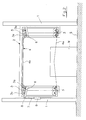
- the apparatus according to the invention has an overall configuration comparable with that of the known art, comprising therefore a pair of uprights 1, standing on the surface of the ground S, mutually spaced so as to permit the positioning of a block of material M to be cut between them; the block M is generically parallelepiped and is represented in figure 2.
- the two uprights 1 slidably support a frame 2, which, under the action of conventional driving means (not shown), is adapted to be progressively moved downward during the sawing operations, and be moved upward again after the work has been completed.
- a frame 2 which, under the action of conventional driving means (not shown), is adapted to be progressively moved downward during the sawing operations, and be moved upward again after the work has been completed.
- banks of rollers 3 are mounted, guiding and directing the diamond wire 4 set for sawing.
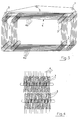
- a single wire 4 is used which is wound in coaxial loops between rollers 3.
- the latter are arranged in banks, each bank comprising a plurality of coaxially adjacent rollers.
- the banks are in turn distributed on the frame 2, so as to arrange the wire 4 in substantially quadrilateral loops whose vertices are defined by the engagement with the banks.
- Each loop comprise, in particular, in addition to the vertical lines running along the uprights 2, horizontal lines 4a, 4b taut between the uprights themselves, of which the lower line 4a is the long one which carries out the sawing.
- the wire 4 then extends with spiral-like progression between the rollers 3 of the various banks, the axis of the spiral being arranged parallel to the axes of the banks, the various parallel-arranged loops determining, with their number, the number of cuts which the apparatus is capable of simultaneously carrying out on the material M.
- the movement of the wire in this case once again in accordance with the prior art, takes place due to the rotation given to one of the banks of rollers 3 by further driving means (not shown).
- the two banks are moreover axially staggered with respect to each other by an amount equal to half of the pitch of the rollers in a single bank.
- the staggering is reversed between the two sides of the apparatus, such that if in one upright 2 the more internal banks are staggered in one direction, in the other upright it will be the more external groups which are staggered in the same direction.
- a position detection sensor is arranged along the upright 2 in order to detect the attainment of a pre-established height of the counterweight 9.
- the sensor not shown, is arranged between the counterweight 9 and the deflection reel 8, and is connected for the signal transmission to a control system having obvious characteristics, not shown; the control system is capable of switching off the driving motor that lowers the frame 2, in response to a signal emitted when the pre-established height is reached by the counterweight 9.
- Such control system is moreover capable of detecting the power absorption of the motor (or motors) which drive the cutting motion of the wire 4, and to interrupt the power feed to the frame-lowering motor upon comparison of the aforesaid absorption with pre-set absorption values corresponding with a standard working condition, a limit stress condition and a minimum stress condition.
- the apparatus according to the invention operates in the following manner.
- the counterweight 9 is adjusted so to realise the desired tensioning of the wire. Since this is a single wire 4, it is evident that, upon the variation of the counterweight mass, and upon the corresponding variation of the position of the pair of roller banks controlled by the counterweight itself, there will be a greater or lesser tensioning of the wire; the tensioning will be constant along all parts of the wire. Such tensioning is in particular reflected in a certain V-shaped deformation of the cutting lines 4a of the wire 4, when, due to the lowering of the frame 2, they engage with the material to be cut, sustaining therefore an upward-directed cutting force.
- the stretching involves an increase of the extent of the deformation of the cutting line, and a consequent descent of the upper roller banks along the related guides, and finally a rising of the counterweight 9.
- the counterweight due to the previously carried out calibration, arrives at the level where the sensor is placed.
- the sensor detecting the presence of the counterweight, emits the switch-off signal of the motor controlling the lowering of the frame 2.
- the diamond wire 4 continues to cut, progressively recovering the excessive deformation and hence the counterweight 9 is made to descend once again.
- the sensor detects the descent, and inferring from this that the deformation has once again assumed a correct extent, it reinitiates the descending action of the frame 2.
- the tensioning of the cutting lines 4a in addition to always remaining uniform among the lines, can therefore be maintained in a reliable manner, within the limits considered suitable for an optimal cutting.
- An additional control is provided, as mentioned above, related with the power absorption by the driving motor of the rollers, and therefore of the movement of the wire along its own axis.
- the frame-lowering motor is switched off. The cutting force tends to diminish, and consequently the power absorption of the wire driving motor decreases.
- the frame-lowering motor is restarted. In case the maximum permitted value is exceeded, this evidently indicating that critical conditions are reached, the control system stops the entire apparatus, sending an alarm signal at the same time.
- the apparatus according to the invention fully attains the stated objects, permitting the obtainment of much thinner material slabs than that which can be currently achieved with the known devices, without affecting the strength and reliability of the apparatus since the pitch of the single banks, and therefore the dimensions of the related rollers, are safely maintained, and the reduced spacing between the cutting lines is obtained by mutually staggered double banks.
- the adoption of a single wire moreover permits maintaining uniform tensioning of the various cutting lines and also permits controlling such tensioning, as seen above, through a simple structural expedient such as that of the slidable mounting of one or more banks of rollers and related position control.
- the structure with double, staggered banks of rollers can be realised with varying geometries and configurations, provided that they are capable of ensuring the spiral progression of the wire as described above, with the wire that, winding around a roller of a bank, is capable of inserting itself - and freely sliding - in the space between the rollers of the adjacent bank, or vice versa.
Landscapes
- Engineering & Computer Science (AREA)
- Mechanical Engineering (AREA)
- Mining & Mineral Resources (AREA)
- Processing Of Stones Or Stones Resemblance Materials (AREA)
- Road Paving Structures (AREA)
- Addition Polymer Or Copolymer, Post-Treatments, Or Chemical Modifications (AREA)
- Finishing Walls (AREA)
Applications Claiming Priority (1)
| Application Number | Priority Date | Filing Date | Title |
|---|---|---|---|
| IT000166A ITFI20050166A1 (it) | 2005-07-22 | 2005-07-22 | Attrezzatura per la segagione di materiali lapidei |
Publications (3)
| Publication Number | Publication Date |
|---|---|
| EP1745875A2 true EP1745875A2 (de) | 2007-01-24 |
| EP1745875A3 EP1745875A3 (de) | 2008-11-19 |
| EP1745875B1 EP1745875B1 (de) | 2011-06-29 |
Family
ID=37309347
Family Applications (1)
| Application Number | Title | Priority Date | Filing Date |
|---|---|---|---|
| EP06117472A Not-in-force EP1745875B1 (de) | 2005-07-22 | 2006-07-19 | Vorrichtung zum Sägen von Gestein |
Country Status (3)
| Country | Link |
|---|---|
| EP (1) | EP1745875B1 (de) |
| AT (1) | ATE514510T1 (de) |
| IT (1) | ITFI20050166A1 (de) |
Cited By (9)
| Publication number | Priority date | Publication date | Assignee | Title |
|---|---|---|---|---|
| ITMI20100263A1 (it) * | 2010-02-19 | 2011-08-20 | Barsanti Macchine S P A | Apparecchiatura per la variazione dello spessore di taglio a passo 10mm di fili di macchine per il taglio di lapidei |
| US20120272943A1 (en) * | 2011-04-29 | 2012-11-01 | Guilin Champion Union Diamond Co., Ltd. | Diamond wire saw device |
| RU2558561C2 (ru) * | 2011-04-29 | 2015-08-10 | Гуйлинь Чемпион Юнион Даймонд Ко., Лтд | Алмазная проволочная пила |
| CN106032757A (zh) * | 2015-03-20 | 2016-10-19 | 赵兵 | 可变向盲切轮组 |
| CN107351270A (zh) * | 2017-09-12 | 2017-11-17 | 中国有色桂林矿产地质研究院有限公司 | 单根柔性线锯开方装置 |
| CN107364025A (zh) * | 2017-09-15 | 2017-11-21 | 中国有色桂林矿产地质研究院有限公司 | 金刚石线单线单向多刀切割装置 |
| CN111993602A (zh) * | 2020-09-22 | 2020-11-27 | 厦门品河机械制造有限公司 | 一种石材承载装置以及金刚线石材切割机 |
| FR3096603A1 (fr) * | 2019-05-29 | 2020-12-04 | Commissariat à l'Energie Atomique et aux Energies Alternatives | Dispositif de découpe à fil de découpe adoptant la forme d’une boucle fermée |
| CN119795350A (zh) * | 2025-03-14 | 2025-04-11 | 河南万美新型建材有限公司 | 一种加气砖脱模横切设备及使用方法 |
Citations (1)
| Publication number | Priority date | Publication date | Assignee | Title |
|---|---|---|---|---|
| DE366600C (de) | 1921-10-18 | 1923-01-08 | Otto Burkhardt Dipl Ing | Steinsaege |
Family Cites Families (2)
| Publication number | Priority date | Publication date | Assignee | Title |
|---|---|---|---|---|
| DE548791C (de) * | 1931-04-23 | 1932-04-19 | Ewald Mies | Steinsaege, bei der zur gleichzeitigen Vornahme mehrerer Schnitte ein endloses Drahtseil verwendet wird |
| JP2674207B2 (ja) * | 1989-05-08 | 1997-11-12 | 住友金属工業株式会社 | 脆性材料の切断加工方法 |
-
2005
- 2005-07-22 IT IT000166A patent/ITFI20050166A1/it unknown
-
2006
- 2006-07-19 AT AT06117472T patent/ATE514510T1/de not_active IP Right Cessation
- 2006-07-19 EP EP06117472A patent/EP1745875B1/de not_active Not-in-force
Patent Citations (1)
| Publication number | Priority date | Publication date | Assignee | Title |
|---|---|---|---|---|
| DE366600C (de) | 1921-10-18 | 1923-01-08 | Otto Burkhardt Dipl Ing | Steinsaege |
Cited By (11)
| Publication number | Priority date | Publication date | Assignee | Title |
|---|---|---|---|---|
| ITMI20100263A1 (it) * | 2010-02-19 | 2011-08-20 | Barsanti Macchine S P A | Apparecchiatura per la variazione dello spessore di taglio a passo 10mm di fili di macchine per il taglio di lapidei |
| EP2361710A1 (de) * | 2010-02-19 | 2011-08-31 | Barsanti Macchine S.p.A. | Einrichtung zum Variieren der Schneidedicke im Abstand von 10 mm von Maschinendraht zum Schneiden von Steinmaterialen. |
| US20120272943A1 (en) * | 2011-04-29 | 2012-11-01 | Guilin Champion Union Diamond Co., Ltd. | Diamond wire saw device |
| RU2558561C2 (ru) * | 2011-04-29 | 2015-08-10 | Гуйлинь Чемпион Юнион Даймонд Ко., Лтд | Алмазная проволочная пила |
| CN106032757A (zh) * | 2015-03-20 | 2016-10-19 | 赵兵 | 可变向盲切轮组 |
| CN106032757B (zh) * | 2015-03-20 | 2018-01-23 | 赵兵 | 可变向盲切轮组 |
| CN107351270A (zh) * | 2017-09-12 | 2017-11-17 | 中国有色桂林矿产地质研究院有限公司 | 单根柔性线锯开方装置 |
| CN107364025A (zh) * | 2017-09-15 | 2017-11-21 | 中国有色桂林矿产地质研究院有限公司 | 金刚石线单线单向多刀切割装置 |
| FR3096603A1 (fr) * | 2019-05-29 | 2020-12-04 | Commissariat à l'Energie Atomique et aux Energies Alternatives | Dispositif de découpe à fil de découpe adoptant la forme d’une boucle fermée |
| CN111993602A (zh) * | 2020-09-22 | 2020-11-27 | 厦门品河机械制造有限公司 | 一种石材承载装置以及金刚线石材切割机 |
| CN119795350A (zh) * | 2025-03-14 | 2025-04-11 | 河南万美新型建材有限公司 | 一种加气砖脱模横切设备及使用方法 |
Also Published As
| Publication number | Publication date |
|---|---|
| EP1745875A3 (de) | 2008-11-19 |
| ITFI20050166A1 (it) | 2007-01-23 |
| EP1745875B1 (de) | 2011-06-29 |
| ATE514510T1 (de) | 2011-07-15 |
Similar Documents
| Publication | Publication Date | Title |
|---|---|---|
| EP1745875B1 (de) | Vorrichtung zum Sägen von Gestein | |
| KR100287607B1 (ko) | 경질(硬質)재료의블록을다수의판으로절단하는방법및그방법을수행하기위한와이어톱(wiresaw) | |
| US5364043A (en) | Arrangement in a coil winding machine for a cable or a similar strandlike product | |
| US20120048255A1 (en) | Wire saw | |
| KR20120130193A (ko) | 실톱 | |
| CN109877984B (zh) | 多段式半导体晶棒截断机 | |
| JP2005219059A (ja) | 鉄筋曲げ機の鉄筋送り込み装置 | |
| US4067312A (en) | Automatic feedback control for wire saw | |
| EP3160673A1 (de) | Drahtformmaschine zum schneiden von blöcken aus natursteinmaterial | |
| KR101402237B1 (ko) | 가이드롤러의 마멸에 따른 와이어 권취오차의 보상장치 및 그것이 설치된 와이어소 | |
| CN100594086C (zh) | 用于对石材进行多金属丝切割的机械 | |
| CN218289806U (zh) | 一种放料设备 | |
| JP7105433B2 (ja) | 切断補助装置およびそれを有するワイヤー式切断装置 | |
| JP4609887B2 (ja) | ワイヤ式切断機 | |
| EP3356072A1 (de) | Multidrahtrahmen und verfahren zum schneiden von steinblöcken in fliesen | |
| CN113746278B (zh) | 一种牵引电机铜条自动涨紧设备 | |
| EP4046734B1 (de) | Multidrahtrahmen zum schneiden von steinblöcken in fliesen | |
| CN112936451B (zh) | 一种具有防护机构的液压机械加工设备 | |
| JP5250376B2 (ja) | ワイヤ巻取り装置およびワイヤソー | |
| KR102248009B1 (ko) | 웨이퍼 래핑 장치 및 그 제어 방법 | |
| EP2952309A1 (de) | Nagelmaschine zum nageln von mindestens zwei übereinander angeordneter schichten von streifen | |
| CN219054580U (zh) | 一种切胶装置 | |
| KR20100025246A (ko) | 웨이퍼의 정상적재 여부 감지장치 및 그 방법 | |
| CN215707619U (zh) | 一种具有矫正机构的包装膜传输设备 | |
| CN112875419A (zh) | 一种电机线圈制造用漆包线自动加工方法 |
Legal Events
| Date | Code | Title | Description |
|---|---|---|---|
| PUAI | Public reference made under article 153(3) epc to a published international application that has entered the european phase |
Free format text: ORIGINAL CODE: 0009012 |
|
| AK | Designated contracting states |
Kind code of ref document: A2 Designated state(s): AT BE BG CH CY CZ DE DK EE ES FI FR GB GR HU IE IS IT LI LT LU LV MC NL PL PT RO SE SI SK TR |
|
| AX | Request for extension of the european patent |
Extension state: AL BA HR MK YU |
|
| PUAL | Search report despatched |
Free format text: ORIGINAL CODE: 0009013 |
|
| AK | Designated contracting states |
Kind code of ref document: A3 Designated state(s): AT BE BG CH CY CZ DE DK EE ES FI FR GB GR HU IE IS IT LI LT LU LV MC NL PL PT RO SE SI SK TR |
|
| AX | Request for extension of the european patent |
Extension state: AL BA HR MK RS |
|
| AKX | Designation fees paid | ||
| REG | Reference to a national code |
Ref country code: DE Ref legal event code: 8566 |
|
| RBV | Designated contracting states (corrected) |
Designated state(s): AT BE BG CH CY CZ DE DK EE ES FI FR GB GR HU IE IS IT LI LT LU LV MC NL PL PT RO SE SI SK TR |
|
| 17Q | First examination report despatched |
Effective date: 20091001 |
|
| 17P | Request for examination filed |
Effective date: 20090902 |
|
| GRAP | Despatch of communication of intention to grant a patent |
Free format text: ORIGINAL CODE: EPIDOSNIGR1 |
|
| GRAS | Grant fee paid |
Free format text: ORIGINAL CODE: EPIDOSNIGR3 |
|
| GRAA | (expected) grant |
Free format text: ORIGINAL CODE: 0009210 |
|
| AK | Designated contracting states |
Kind code of ref document: B1 Designated state(s): AT BE BG CH CY CZ DE DK EE ES FI FR GB GR HU IE IS IT LI LT LU LV MC NL PL PT RO SE SI SK TR |
|
| REG | Reference to a national code |
Ref country code: GB Ref legal event code: FG4D |
|
| REG | Reference to a national code |
Ref country code: CH Ref legal event code: EP |
|
| REG | Reference to a national code |
Ref country code: IE Ref legal event code: FG4D |
|
| REG | Reference to a national code |
Ref country code: DE Ref legal event code: R096 Ref document number: 602006022752 Country of ref document: DE Effective date: 20110825 |
|
| REG | Reference to a national code |
Ref country code: NL Ref legal event code: VDEP Effective date: 20110629 |
|
| PG25 | Lapsed in a contracting state [announced via postgrant information from national office to epo] |
Ref country code: LT Free format text: LAPSE BECAUSE OF FAILURE TO SUBMIT A TRANSLATION OF THE DESCRIPTION OR TO PAY THE FEE WITHIN THE PRESCRIBED TIME-LIMIT Effective date: 20110629 Ref country code: SE Free format text: LAPSE BECAUSE OF FAILURE TO SUBMIT A TRANSLATION OF THE DESCRIPTION OR TO PAY THE FEE WITHIN THE PRESCRIBED TIME-LIMIT Effective date: 20110629 |
|
| PG25 | Lapsed in a contracting state [announced via postgrant information from national office to epo] |
Ref country code: GR Free format text: LAPSE BECAUSE OF FAILURE TO SUBMIT A TRANSLATION OF THE DESCRIPTION OR TO PAY THE FEE WITHIN THE PRESCRIBED TIME-LIMIT Effective date: 20110930 Ref country code: FI Free format text: LAPSE BECAUSE OF FAILURE TO SUBMIT A TRANSLATION OF THE DESCRIPTION OR TO PAY THE FEE WITHIN THE PRESCRIBED TIME-LIMIT Effective date: 20110629 Ref country code: LV Free format text: LAPSE BECAUSE OF FAILURE TO SUBMIT A TRANSLATION OF THE DESCRIPTION OR TO PAY THE FEE WITHIN THE PRESCRIBED TIME-LIMIT Effective date: 20110629 Ref country code: SI Free format text: LAPSE BECAUSE OF FAILURE TO SUBMIT A TRANSLATION OF THE DESCRIPTION OR TO PAY THE FEE WITHIN THE PRESCRIBED TIME-LIMIT Effective date: 20110629 Ref country code: AT Free format text: LAPSE BECAUSE OF FAILURE TO SUBMIT A TRANSLATION OF THE DESCRIPTION OR TO PAY THE FEE WITHIN THE PRESCRIBED TIME-LIMIT Effective date: 20110629 |
|
| PGFP | Annual fee paid to national office [announced via postgrant information from national office to epo] |
Ref country code: FR Payment date: 20110818 Year of fee payment: 6 Ref country code: GB Payment date: 20110819 Year of fee payment: 6 |
|
| PG25 | Lapsed in a contracting state [announced via postgrant information from national office to epo] |
Ref country code: BE Free format text: LAPSE BECAUSE OF FAILURE TO SUBMIT A TRANSLATION OF THE DESCRIPTION OR TO PAY THE FEE WITHIN THE PRESCRIBED TIME-LIMIT Effective date: 20110629 |
|
| PG25 | Lapsed in a contracting state [announced via postgrant information from national office to epo] |
Ref country code: CZ Free format text: LAPSE BECAUSE OF FAILURE TO SUBMIT A TRANSLATION OF THE DESCRIPTION OR TO PAY THE FEE WITHIN THE PRESCRIBED TIME-LIMIT Effective date: 20110629 Ref country code: NL Free format text: LAPSE BECAUSE OF FAILURE TO SUBMIT A TRANSLATION OF THE DESCRIPTION OR TO PAY THE FEE WITHIN THE PRESCRIBED TIME-LIMIT Effective date: 20110629 Ref country code: IS Free format text: LAPSE BECAUSE OF FAILURE TO SUBMIT A TRANSLATION OF THE DESCRIPTION OR TO PAY THE FEE WITHIN THE PRESCRIBED TIME-LIMIT Effective date: 20111029 Ref country code: EE Free format text: LAPSE BECAUSE OF FAILURE TO SUBMIT A TRANSLATION OF THE DESCRIPTION OR TO PAY THE FEE WITHIN THE PRESCRIBED TIME-LIMIT Effective date: 20110629 Ref country code: PT Free format text: LAPSE BECAUSE OF FAILURE TO SUBMIT A TRANSLATION OF THE DESCRIPTION OR TO PAY THE FEE WITHIN THE PRESCRIBED TIME-LIMIT Effective date: 20111031 |
|
| PG25 | Lapsed in a contracting state [announced via postgrant information from national office to epo] |
Ref country code: CY Free format text: LAPSE BECAUSE OF FAILURE TO SUBMIT A TRANSLATION OF THE DESCRIPTION OR TO PAY THE FEE WITHIN THE PRESCRIBED TIME-LIMIT Effective date: 20110629 Ref country code: PL Free format text: LAPSE BECAUSE OF FAILURE TO SUBMIT A TRANSLATION OF THE DESCRIPTION OR TO PAY THE FEE WITHIN THE PRESCRIBED TIME-LIMIT Effective date: 20110629 Ref country code: SK Free format text: LAPSE BECAUSE OF FAILURE TO SUBMIT A TRANSLATION OF THE DESCRIPTION OR TO PAY THE FEE WITHIN THE PRESCRIBED TIME-LIMIT Effective date: 20110629 Ref country code: MC Free format text: LAPSE BECAUSE OF NON-PAYMENT OF DUE FEES Effective date: 20110731 Ref country code: RO Free format text: LAPSE BECAUSE OF FAILURE TO SUBMIT A TRANSLATION OF THE DESCRIPTION OR TO PAY THE FEE WITHIN THE PRESCRIBED TIME-LIMIT Effective date: 20110629 |
|
| REG | Reference to a national code |
Ref country code: CH Ref legal event code: PL |
|
| REG | Reference to a national code |
Ref country code: IE Ref legal event code: MM4A |
|
| PG25 | Lapsed in a contracting state [announced via postgrant information from national office to epo] |
Ref country code: CH Free format text: LAPSE BECAUSE OF NON-PAYMENT OF DUE FEES Effective date: 20110731 Ref country code: LI Free format text: LAPSE BECAUSE OF NON-PAYMENT OF DUE FEES Effective date: 20110731 |
|
| PLBE | No opposition filed within time limit |
Free format text: ORIGINAL CODE: 0009261 |
|
| STAA | Information on the status of an ep patent application or granted ep patent |
Free format text: STATUS: NO OPPOSITION FILED WITHIN TIME LIMIT |
|
| PG25 | Lapsed in a contracting state [announced via postgrant information from national office to epo] |
Ref country code: IT Free format text: LAPSE BECAUSE OF FAILURE TO SUBMIT A TRANSLATION OF THE DESCRIPTION OR TO PAY THE FEE WITHIN THE PRESCRIBED TIME-LIMIT Effective date: 20110629 |
|
| 26N | No opposition filed |
Effective date: 20120330 |
|
| PG25 | Lapsed in a contracting state [announced via postgrant information from national office to epo] |
Ref country code: DK Free format text: LAPSE BECAUSE OF FAILURE TO SUBMIT A TRANSLATION OF THE DESCRIPTION OR TO PAY THE FEE WITHIN THE PRESCRIBED TIME-LIMIT Effective date: 20110629 |
|
| PG25 | Lapsed in a contracting state [announced via postgrant information from national office to epo] |
Ref country code: IE Free format text: LAPSE BECAUSE OF NON-PAYMENT OF DUE FEES Effective date: 20110719 |
|
| REG | Reference to a national code |
Ref country code: DE Ref legal event code: R097 Ref document number: 602006022752 Country of ref document: DE Effective date: 20120330 |
|
| GBPC | Gb: european patent ceased through non-payment of renewal fee |
Effective date: 20120719 |
|
| REG | Reference to a national code |
Ref country code: FR Ref legal event code: ST Effective date: 20130329 |
|
| PG25 | Lapsed in a contracting state [announced via postgrant information from national office to epo] |
Ref country code: GB Free format text: LAPSE BECAUSE OF NON-PAYMENT OF DUE FEES Effective date: 20120719 Ref country code: ES Free format text: LAPSE BECAUSE OF FAILURE TO SUBMIT A TRANSLATION OF THE DESCRIPTION OR TO PAY THE FEE WITHIN THE PRESCRIBED TIME-LIMIT Effective date: 20111010 Ref country code: DE Free format text: LAPSE BECAUSE OF NON-PAYMENT OF DUE FEES Effective date: 20130201 Ref country code: FR Free format text: LAPSE BECAUSE OF NON-PAYMENT OF DUE FEES Effective date: 20120731 |
|
| REG | Reference to a national code |
Ref country code: DE Ref legal event code: R119 Ref document number: 602006022752 Country of ref document: DE Effective date: 20130201 |
|
| PG25 | Lapsed in a contracting state [announced via postgrant information from national office to epo] |
Ref country code: LU Free format text: LAPSE BECAUSE OF NON-PAYMENT OF DUE FEES Effective date: 20110719 |
|
| PG25 | Lapsed in a contracting state [announced via postgrant information from national office to epo] |
Ref country code: BG Free format text: LAPSE BECAUSE OF FAILURE TO SUBMIT A TRANSLATION OF THE DESCRIPTION OR TO PAY THE FEE WITHIN THE PRESCRIBED TIME-LIMIT Effective date: 20110929 |
|
| PG25 | Lapsed in a contracting state [announced via postgrant information from national office to epo] |
Ref country code: TR Free format text: LAPSE BECAUSE OF FAILURE TO SUBMIT A TRANSLATION OF THE DESCRIPTION OR TO PAY THE FEE WITHIN THE PRESCRIBED TIME-LIMIT Effective date: 20110629 |
|
| PG25 | Lapsed in a contracting state [announced via postgrant information from national office to epo] |
Ref country code: HU Free format text: LAPSE BECAUSE OF FAILURE TO SUBMIT A TRANSLATION OF THE DESCRIPTION OR TO PAY THE FEE WITHIN THE PRESCRIBED TIME-LIMIT Effective date: 20110629 |
|
| PGFP | Annual fee paid to national office [announced via postgrant information from national office to epo] |
Ref country code: DE Payment date: 20110810 Year of fee payment: 6 |