EP1744685B1 - Joints pour trocarts - Google Patents
Joints pour trocarts Download PDFInfo
- Publication number
- EP1744685B1 EP1744685B1 EP05741669A EP05741669A EP1744685B1 EP 1744685 B1 EP1744685 B1 EP 1744685B1 EP 05741669 A EP05741669 A EP 05741669A EP 05741669 A EP05741669 A EP 05741669A EP 1744685 B1 EP1744685 B1 EP 1744685B1
- Authority
- EP
- European Patent Office
- Prior art keywords
- seal
- support
- ring
- extending
- flexible seal
- Prior art date
- Legal status (The legal status is an assumption and is not a legal conclusion. Google has not performed a legal analysis and makes no representation as to the accuracy of the status listed.)
- Expired - Fee Related
Links
Images


Classifications
-
- A—HUMAN NECESSITIES
- A61—MEDICAL OR VETERINARY SCIENCE; HYGIENE
- A61B—DIAGNOSIS; SURGERY; IDENTIFICATION
- A61B17/00—Surgical instruments, devices or methods, e.g. tourniquets
- A61B17/34—Trocars; Puncturing needles
- A61B17/3462—Trocars; Puncturing needles with means for changing the diameter or the orientation of the entrance port of the cannula, e.g. for use with different-sized instruments, reduction ports, adapter seals
-
- A—HUMAN NECESSITIES
- A61—MEDICAL OR VETERINARY SCIENCE; HYGIENE
- A61B—DIAGNOSIS; SURGERY; IDENTIFICATION
- A61B17/00—Surgical instruments, devices or methods, e.g. tourniquets
- A61B17/34—Trocars; Puncturing needles
-
- A—HUMAN NECESSITIES
- A61—MEDICAL OR VETERINARY SCIENCE; HYGIENE
- A61B—DIAGNOSIS; SURGERY; IDENTIFICATION
- A61B17/00—Surgical instruments, devices or methods, e.g. tourniquets
- A61B17/34—Trocars; Puncturing needles
- A61B17/3417—Details of tips or shafts, e.g. grooves, expandable, bendable; Multiple coaxial sliding cannulas, e.g. for dilating
-
- A—HUMAN NECESSITIES
- A61—MEDICAL OR VETERINARY SCIENCE; HYGIENE
- A61B—DIAGNOSIS; SURGERY; IDENTIFICATION
- A61B17/00—Surgical instruments, devices or methods, e.g. tourniquets
- A61B17/34—Trocars; Puncturing needles
- A61B17/3494—Trocars; Puncturing needles with safety means for protection against accidental cutting or pricking, e.g. limiting insertion depth, pressure sensors
- A61B17/3496—Protecting sleeves or inner probes; Retractable tips
-
- A—HUMAN NECESSITIES
- A61—MEDICAL OR VETERINARY SCIENCE; HYGIENE
- A61B—DIAGNOSIS; SURGERY; IDENTIFICATION
- A61B17/00—Surgical instruments, devices or methods, e.g. tourniquets
- A61B17/34—Trocars; Puncturing needles
- A61B17/3498—Valves therefor, e.g. flapper valves, slide valves
-
- A—HUMAN NECESSITIES
- A61—MEDICAL OR VETERINARY SCIENCE; HYGIENE
- A61B—DIAGNOSIS; SURGERY; IDENTIFICATION
- A61B17/00—Surgical instruments, devices or methods, e.g. tourniquets
- A61B17/34—Trocars; Puncturing needles
- A61B17/3474—Insufflating needles, e.g. Veress needles
-
- A—HUMAN NECESSITIES
- A61—MEDICAL OR VETERINARY SCIENCE; HYGIENE
- A61B—DIAGNOSIS; SURGERY; IDENTIFICATION
- A61B17/00—Surgical instruments, devices or methods, e.g. tourniquets
- A61B2017/0042—Surgical instruments, devices or methods, e.g. tourniquets with special provisions for gripping
-
- A—HUMAN NECESSITIES
- A61—MEDICAL OR VETERINARY SCIENCE; HYGIENE
- A61B—DIAGNOSIS; SURGERY; IDENTIFICATION
- A61B17/00—Surgical instruments, devices or methods, e.g. tourniquets
- A61B2017/0042—Surgical instruments, devices or methods, e.g. tourniquets with special provisions for gripping
- A61B2017/00424—Surgical instruments, devices or methods, e.g. tourniquets with special provisions for gripping ergonomic, e.g. fitting in fist
-
- A—HUMAN NECESSITIES
- A61—MEDICAL OR VETERINARY SCIENCE; HYGIENE
- A61B—DIAGNOSIS; SURGERY; IDENTIFICATION
- A61B17/00—Surgical instruments, devices or methods, e.g. tourniquets
- A61B2017/00477—Coupling
Definitions
- This invention relates generally to surgical instruments, and more for particularly to seals for trocar systems for providing an opening through tissue and into body cavities and through which surgical instruments may be inserted.
- Trocar systems are surgical devices used to obtain access to a body cavity to perform various surgical procedures such as laparoscopic surgery or arthroscopic surgery.
- a trocar system typically includes a pointed rod-like device or obturator fitted into a tube-like device or cannula.
- the cannula head of the cannula often has one or more seals.
- a pointed end of the obturator projects out an end of a cannula tube and is used to penetrate the outer tissue of the cavity. Alter the tissue is penetrated and the body cavity is accessed by the trocar system, the obturator is then withdrawn while the cannula tube is retained in the cavity. The body cavity can then be accessed by surgical instruments via the cannula tube to perform various surgical procedures, or the cannula can simply be used as a drainage outlet.
- the present invention provides a seal with a seal according to claim 1.
- the present invention provides a method for sealing a cannula head with a seal according to claim 1.
- the present invention provides cannula heads and trocar systems that include the above-described seals.
- FIG. 1 is a perspective view of a dilating trocar system in accordance with the present invention
- FIG. 2 is a perspective view of a cutting trocar system in accordance with the present invention.
- FIG. 3 is a side elevational view, in part cross-section, of the dilating trocar system of FIG. 1 showing the obturator removed from the cannula;
- FIG. 4 is a side elevational view, in part cross-section, of the cutting trocar system of FIG. 2 showing the obturator removed from the cannula;
- FIG. 5 is an enlarged, exploded, cross-sectional view of the cannula of FIGS. 1 and 2 and a releasably attachable upper seal in accordance with the present invention
- FIG. 6 is an enlarged, exploded, cross-sectional view of the cannula head of FIGS. 1 and 2 showing a lower seal with a flapper valve open;
- FIG. 7 is an exploded, perspective view of the lower seal of FIG. 6 ;
- FIG. 8 is an exploded, cross-sectional view of the lower seal of FIG. 6 ;
- FIG. 9 is an enlarged perspective view, partially cutaway, of the releasably attachable upper seal of FIG. 5 ;
- FIG. 10 is a top view of the protective covering guide of the releasably attachable upper seal shown in FIG. 9 ;
- FIG. 11 is a cross-sectional view of the releasably attachable upper seal of FIG. 9 ;
- FIG. 12 is a cross-sectional view of another embodiment of a releasably attachable upper seal in accordance with the present invention.
- FIG. 13 is a cross-sectional view of another embodiment of a releasably attachable upper seal in accordance with the present invention.
- FIG. 14 is a top view of a cannula head with a releasably attachable upper seal shown in dashed lines in an unlocked position;
- FIG. 15 is a top view of a cannula head with a releasably attachable upper seal shown in a locked position;
- FIG. 16 is a cross-sectional view of a releasably attachable upper seal with an obturator extending therethrough;
- FIG. 17 is a cross-sectional view of a releasably attachable upper seal with an obturator off centered extending therethrough.
- FIGS. 1 and 2 illustrate perspective views of a dilating trocar system 10 and a safety-shielded cutting trocar system 12, respectively, which may incorporate a seal in accordance with the present invention as explained in greater detail below.
- dilating trocar system 10 generally includes a cannula 100 having a cannula head 110 and a cannula tube 300 into which is slidably receivable a dilating obturator 400 having an obturator cap 410 attached to an elongated shaft 450 ( FIG. 3 ) having a pointed end 452 which may have a rounded point at its distal end.
- a cannula 100 having a cannula head 110 and a cannula tube 300 into which is slidably receivable a dilating obturator 400 having an obturator cap 410 attached to an elongated shaft 450 ( FIG. 3 ) having a pointed end 452 which may have a rounded point
- trocar system 12 generally includes a cannula 500 having a cannula head 510 and a cannula tube 600 into which is slidably receivable a safety shielded cutting obturator 700 having a cap 800 and a spring-loaded shield 710 and automatically-operated spring-loaded locking mechanism for inhibiting the exposure of a cutting blade (not shown) after passing through tissue or muscle.
- the cutting trocar system cuts or lacerates tissue when obtaining access to a body cavity.
- the dilating trocar systems allow parting and stretching of, for example, multiple cross-directional muscle layers and intra-abdominal blood vessels, when gaining access to a body cavity.
- trocar systems may include one or more of the various features described in U.S. Patent Application No. US 2003/060770 .
- the cannulas may include a cannula housing 130, resilient non-slip material 140, a releasably attachable stopcock valve 170, a lower seal 180, and a releasably attachable upper seal 200.
- lower seal 180 includes an outer support 182, a flapper valve 190, and a retainer cap 198.
- Lower seal 180 is sealably attached across passageway 136 ( FIG. 6 ) in cannula housing 130 ( FIG. 6 ) behind stopcock valve 170 (best shown in FIG. 5 ).
- an outer edge 185 of a lateral flange 184 may be attached with an adhesive (or other suitable means for forming a complete seal) along a support or ledge 131 ( FIG. 6 ) formed in cannula housing 130 ( FIG. 6 ) to define a chamber 138 ( FIG. 6 ) in housing 130 ( FIG. 6 ).
- Flapper valve 190 includes a flexible disc-shaped portion 192 (shown in an open position in FIG. 6 ) attached at a portion along its circumference to a flexible collar 194 having a groove 196 ( FIG. 7 ) therein.
- a pair of rigid discs 193 and 195 may be attached to the center of flexible disc-shaped portion 192.
- the rigid discs may add support to and protect the flexible disc-shaped portion when an obturator or other instruments are inserted and removed from the cannula.
- Outer support 182 may be monolithic or integrally formed as one-piece. Outer support 182 may also include a circumferentially extending flange 187 (best shown in FIG.
- flapper valve 190 When no instrument is inserted in the cannula, the flapper valve 190 is normally closed, i.e., biased shut. In addition, if the cannula housing is pressurized with a fluid, the pressurized fluid will exert a pressure against the flapper valve to more securely retain the flapper valve in a sealed position and maintain the pressure in the cannula housing and in the body cavity.
- Retainer cap 198 further secures and maintain flapper valve on outer support 182. In particular, retainer cap 198 aids in retaining collar 194 ( FIG. 6 ) or flapper valve 190 ( FIG. 6 ) on outer support 182 ( FIG.
- Retainer cap may include one or more notches or cutouts (not shown) on the lower portion thereof adjacent to where the flapper valve attaches to flexible collar 194. This notch or notches allow the hinge of the flapper valve to be more flexible and seat properly if caught by a hooked instrument as it is withdrawn from the cannula.
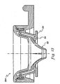
- releasably attachable upper seal 200 may include a rigid distal support 20, a rigid proximal support 40, a rotatable flexible seal 60 having upper portions sandwiched between the supports, a movable ring 90 disposed between the flexible seal and the lower support, and a generally non-compliant, but bendable protective guide 80.
- upper seal assembly 200 is releasably and sealably attachable to the cannula head of the trocar as illustrated in FIG. 5 .
- distal support 20 includes an inner ring-shaped portion 22 having an inwardly-extending flange 23 defining a distal opening, an outer ring-shaped portion 24, and an outwardly-extending arm 26.
- Outwardly extending arm 26 allows a surgeon to readily lock and unlock upper seal assembly 200 to a cannula head, e.g., via a bayonet-style connector as described in greater detail below.
- This locking and unlocking arrangement permits a surgeon to remove upper seal 200 if it becomes necessary during surgery to withdraw a tissue sample or another sizeable item from the surgical site. Otherwise, upper seal 200 generally remains in place during a surgical procedure because it can accept instruments having various diameters.
- Rigid proximal support 40 includes an inwardly-extending flange 42 which defines a proximal opening.
- the openings in distal support 20 and proximal support 40 guide and limit lateral movement of an instrument inserted in upper seal assembly 200.
- Proximal support 40 may also have a concave shape for directing a tip of an instrument through the upper seal.
- the distal and proximal supports may be made from a rigid plastic material.
- Rotatable flexible seal 60 includes a distal centrally located aperture or opening 62 which allows for easy insertion and removal, for example, of an instrument such as an obturator shaft into a cannula head while inhibiting the release of fluid from the cannula head.
- the distal end of rotatable flexible seal 60 may also include and inwardly extending flange 64 which assists in conforming and sealing against relatively small instruments but which flattens out against and conforms to relatively large instruments.
- the distal most portion of rotatable flexible seal 60 also includes a raised sinusoidal portion 81 that extends around the inner, lower portion of the upper seal to define a plurality of inwardly extending lobes. This configuration allows the opening to easily expand and conform around relatively large instruments.
- Rotatable flexible seal 60 further includes an upper seal portion 70 having a horizontally-extending portion 71, an upwardly-extending annular flange 72, and a downwardly-depending annular flange 74.
- the flanges 72 and 74 and a portion of the horizontally-extending portion 71 are fitted between portions of proximal support 40 and an annular groove in distal support 20.
- An outer downwardly-depending flange 45 of proximal support 40 may be received in and fixedly attached, e.g., with adhesive or by ultrasonic welding, to an annular groove in distal support 20.
- Upper seal portion 70 of the rotatable flexible seal is sized slightly smaller than the corresponding cutout formed in the rigid supports. Accordingly, this allows the seal to rotate when an instrument is inserted in and twisted about the central axis C of the seal in the direction of curved double-headed arrow C1.
- the pressurized cannula results in forcing the outer surface of downwardly-depending annular flange 74 against the inside surface of the cutout formed in rigid support 20 to form an airtight seal to seal pressurized gas in the cannula head and prevent leakage.
- Rotatable flexible seal 60 may be made from a resilient or an elastomeric material, for example, a silicone rubber, a polyurethane elastomer, a neoprene or a thermoplastic elastomer.
- a lubricant may be applied to the outer surface of the upper seal 70 (e.g., to the upper flange portion) or to the entire surface of the upper seal 70.
- the lubricant may be a coating, such as parylene.
- Protective guide or liner 80 is attached, for example with an adhesive, along an inner surface of convex seal portion 77.
- a lower portion of the protective guide is spaced apart from or disposed away from opening 62 in rotatable flexible seal 60 in the vicinity of the lobes, short of orifice 62, thus leaving a portion of seal 60 exposed for making a seal with an instrument.
- Protective guide further includes four slits 82, only one of which is shown in FIG. 9 .
- protective guide 80 may be fabricated from a flat sheet initially in the form of an arc such as from a slippery, bendable material such as a thin layer or sheet of plastic.
- Slits 82 are formed extending from an inner portion 84 to a point adjacent to an outer edge of an outer portion 85. Accordingly, when protective guide 80 is attached to the inner surface of convex portion 77 ( FIG. 9 ), edges 86 are disposed adjacent to each other. The slits in the guide permit the opening in the guide to expand radially outward as the width of each slit widens upon insertion of an instrument.
- a movable washer 90 may be disposed between rotatable flexible seal 60 and flange 23.
- the purpose of washer 90 is to restrain the distal movement of flexible seal 60 when an instrument of large diameter is inserted therein and to inhibit the rotatable flexible seal 60 from being stretched distally to such an extent that it becomes jammed at the orifice of the lower flapper valve.
- Movable washer 90 may be made to generally replicate the shape and the dimensions of flange 42 of proximal support 40. For example, the washer may have a curved cross-section. Thus, the central opening in washer 90 may essentially match that of the central opening of flange 42.
- Washer 90 may be fabricated from a rigid plastic material such as Acrylonitrile Butadiene Styrene (ABS), polycarbonate, nylon, etc.
- FIG. 12 illustrates another embodiment of releasably attachable upper seal 202 in accordance with the present invention.
- a ring 92 configured as half of an O-ring (e.g., having a half round cross-section) may be disposed between rotatable flexible seal 60 and flange 23.
- Ring 92 may be formed from a resilient material such as silicone rubber or other suitable material, and may be fixedly attached to flange 23 with an adhesive.
- FIG. 13 illustrates another embodiment of releasably attachable upper seal 204 in accordance with the present invention.
- a flange 24 of rigid distal support 20 is configured to include a raised portion 94 which extends upwardly and inwardly toward flexible seal 60.
- raised portion 94 may be integrally formed as a unit with distal support, i.e., being monolithic or as one piece.
- proximal opening defined by flange 42 may measure about 1/2 of an inch in diameter and the orifice in the seal may measure about 1/8 of an inch in diameter.
- Flange 23 on distal support 20 may define a distal opening measuring about 5/8 of an inch in diameter.
- the washer opening may measure about 1/2 of an inch in diameter.
- a releasable attachable seal is shown in dashed lines in an unlocked position.
- the releasably attachable seal is releasably attached to the cannula head by rotating the releasably attachable seal clockwise.
- the cannula head and the releasably attachable seal may be releasably attachable, for example, via a bayonet-type connector, with the releasably attachable seal having two flexible pins or tabs 27 ( FIG. 11 ) that extend outwardly and engage J-shaped grooves 181 ( FIG. 14 ) in the lower seal of the cannula head. It will be appreciated that other means for releasably attaching the upper seal to the cannula head may be employed.
- indicia 185 and 187 may be provided on the lower seal for indicating the locked and unlocked positions of the releasably attachable upper seal.
- a surgeon may remove the releasably attachable upper seal to provide a greater opening for removing, for example, tissue through the cannula tube and cannula head.
- the aperture of the upper seal may be sized so that the aperture or hole is slightly smaller than an obturator shaft or surgical instrument to be used. This interference fit between the resilient diameter of the aperture and the shaft minimizes the passage of fluid from a cavity to the ambient environment during insertion and removal of an obturator or other instruments.
- the flapper valve provides a seal to the ambient environment.
- the cannula head may have a fixedly attached upper seal.
- the releasably attachable upper seal may include a stationary ring or fixedly attached ring while the flexible seal is operable to rotate within the supports.
- the releasably upper seal may include a nonrotatable flexible seal and a movable or fixedly attached ring. It will also be appreciated that the ring may have other suitable cross-sectional configurations.
- the diameter of the opening in the proximal support, the thickness of the flexible seal, and the diameter of the aperture in the flexible seal may vary depending upon the size of the cannula head, the size of the obturator or other instruments to be used, and the difference in pressure across the flexible seal that needs to be sealed.
- the thickness of the flexible seal may be between about 1 mm to about 3 mm
- the thickness of the protective guide may be about 0,254 mm to about 0,76 mm (0.010 inches to about 0.030 inches).
- the releasably attachable upper seal when assembled, is designed primarily so that any lateral movement of the seal 60 will be rather limited when an instrument is initially inserted off axis. Instead, the instrument is guided or deflected toward the central axis C.
- an instrument such as a shaft of an obturator is ideally inserted along central axis C of the releasably attachable upper seal.
- the opening of the seal 60 expands in the direction of the horizontal arrows to form a seal around its shaft.
- an instrument inserted off axis will simply be deflected by protective guide 80 toward the central axis C.
- the upper portion of flexible seal 60 closest to the shaft is deformed and pushed upwardly against proximal support 40, and the upper portion of flexible seal 60 farthest away from the shaft is pulled downwardly.
- the combination of the flexible seal 60 and protective guide 80 are deformed and disposed on an angle to central axis C and the lowermost portion of flexible seal 60 is deformed and disposed on an angle S around shaft 100.
- the lowermost portion-forming the resulting opening in flexible seal 60 around the shaft is no longer circular but instead oval shaped.
Claims (21)
- Joint (200, 202, 204) pour tête de canule (110, 510), le joint (200, 202, 204) comprenant :- un support (20, 40) définissant un passage s'étendant à travers celui-ci et définissant un axe ;- un joint souple (60) supporté de manière rotative par le support (20, 40) le joint souple (60) comprenant une partie supérieure (70) ayant une partie s'étendant horizontalement (71), et au moins un rebord parmi un rebord annulaire s'étendant vers le haut (72) et un rebord annulaire suspendu vers le bas (74) ; dans lequelle support (20, 40) comprend une découpe pour recevoir la partie supérieure (70) du joint souple (60), les rebords (72, 74) et une partie de la partie s'étendant horizontalement (71) étant disposés dans la découpe et écartés des surfaces de la découpe de sorte qu'un déplacement latéral des rebords (72, 74) est limité ;
caractérisé en ce que le joint souple (60) est supporté de manière rotative par le support (20, 40) de sorte que le joint souple peut tourner uniquement autour de l'axe. - Joint selon la revendication 1, dans lequel le joint (200, 202, 204) comprend une protection (80) ayant plusieurs fentes pour protéger le joint souple (60), et dans lequel le joint souple (60) comprend un revêtement lubrifiant.
- Joint selon la revendication 1, dans lequel le joint (200, 202, 204) peut être fixé de manière libérable sur la tête de canule (110, 510).
- Joint selon la revendication 1, dans lequel au moins un élément du support (20, 40) comprend un bras (26) s'étendant vers l'extérieur à partir du support.
- Joint selon la revendication 4, dans lequel le bras (26) comprend un bouton s'étendant vers le haut.
- Joint selon la revendication 1, dans lequel il comprend de plus un anneau (97, 92, 94) disposé entre une partie inférieure du support (20, 40) et le joint souple (60), et dans lequel l'anneau (90, 92, 94) définit une ouverture de dimension plus petite qu'une ouverture dans la partie inférieure du support (20, 40).
- Joint selon la revendication 6, dans lequel l'anneau (90, 92) est mobile entre le joint souple (60) et la partie inférieure du support (20, 40).
- Joint selon la revendication 6, dans lequel l'anneau (90, 92) est positionné de manière mobile entre le joint souple (60) et la partie inférieure du support (20, 40).
- Joint selon la revendication 6, dans lequel l'anneau (94) est formé d'un seul tenant avec un rebord s'étendant vers l'intérieur (24) de la partie inférieure du support (20, 40) de sorte que l'anneau (94) est disposé vers le haut et vers l'intérieur à partir du rebord s'étendant vers l'intérieur (24).
- Joint selon la revendication 6, dans lequel l'anneau (92, 94) a une section transversale en demi-rond.
- Joint selon la revendication 6, dans lequel l'anneau (90, 92, 94) est constitué d'un matériau rigide et dans lequel le joint (200, 202, 204) comprend une protection (80) ayant plusieurs fentes pour protéger le joint souple (60).
- Tête de canule (110, 510) comprenant :- un boîtier (130) ayant un passage s'étendant à travers celui-ci ; et- un joint (200, 202, 204) selon la revendication 1 disposé à travers le passage.
- Tête de canule selon la revendication 12, dans lequel le joint (200, 202, 204) peut être relié de manière libérable à la tête de canule (110, 510).
- Système de trocart (10, 12) comprenant :- une tête de canule (110, 510) comprenant un boîtier (130) ayant un passage s'étendant à travers celui-ci ;- un joint (200, 202, 204) selon la revendication 1 disposé à travers ledit passage ;- un obturateur (400, 700) pouvant être reçu dans la tête de canule (110, 510) et à travers le joint ; et- un tube de canule (300, 600) pouvant être fixé sur la tête de canule (110, 510).
- Système de trocart selon la revendication 14, dans lequel le joint (200, 202, 204) peut être fixé de manière libérable sur la tête de canule (110, 510).
- Procédé pour rendre étanche une tête de canule (110, 510) ayant un joint selon la revendication 1, le procédé consistant à :- agencer le support (20, 40) dans la tête de canule (110, 510) ayant un passage s'étendant à travers celui-ci définissant un axe ;- agencer le joint souple (60) ; et- monter le joint souple (60) sur le support (20, 40) dans la découpe de sorte que le joint souple (60) soit rotatif autour de l'axe et le au moins un rebord parmi le rebord annulaire s'étendant vers le haut (72) et le rebord annulaire suspendu vers le bas (74) est retenu par la découpe vis-à-vis d'un déplacement latéral.
- Procédé selon la revendication 16 fournissant de plus la découpe dans le support (20, 40), et dans lequel au moins un rebord parmi le rebord annulaire s'étendant vers le haut (72) et le rebord annulaire suspendu vers le bas (74) du joint souple (60) a une dimension plus petite que la découpe.
- Procédé selon la revendication 16, dans lequel le au moins un rebord parmi le rebord annulaire s'étendant vers le haut (72) et le rebord annulaire suspendu vers le bas (74) est disposé dans la découpe et est écarté d'une surface supérieure, des surfaces latérales, et d'une surface de fond de la découpe.
- Procédé selon la revendication 16, comprenant de plus le positionnement d'un anneau (90, 92, 94) ayant une ouverture de dimension plus petite qu'une ouverture inférieure située dans le support entre le support et le joint souple.
- Procédé selon la revendication 16, comprenant de plus la fixation de manière libérable du joint (200, 202, 204) sur la tête de canule (110, 510).
- Procédé selon la revendication 16 comprenant de plus le positionnement d'un anneau (90, 92, 94) dans l'ouverture centrale du support (20, 40) entre une ouverture inférieure du support (20, 40) et le joint souple (60), l'anneau (90, 92, 94) ayant une dimension plus grande que l'ouverture inférieure et ayant une ouverture intérieure de dimension plus petite que l'ouverture inférieure du support (20, 40), dans lequel au moins un élément de l'anneau (90, 92) est positionné de manière mobile entre le joint souple (60) et le support (20, 40), l'anneau (94) étant formé d'un seul tenant sous la forme d'une seule pièce avec un rebord s'étendant vers l'intérieur (24) de la partie inférieure du support (20, 40) de sorte que l'anneau (94) est disposé vers le haut et vers l'intérieur à partir du rebord s'étendant vers l'intérieur (24), et l'anneau (92, 94) comprenant une section transversale en demi-rond.
Applications Claiming Priority (2)
| Application Number | Priority Date | Filing Date | Title |
|---|---|---|---|
| US10/839,776 US20040260244A1 (en) | 2001-08-31 | 2004-05-05 | Seals for trocars |
| PCT/US2005/014393 WO2005112799A2 (fr) | 2004-05-05 | 2005-04-27 | Joints pour trocarts |
Publications (2)
| Publication Number | Publication Date |
|---|---|
| EP1744685A2 EP1744685A2 (fr) | 2007-01-24 |
| EP1744685B1 true EP1744685B1 (fr) | 2012-10-17 |
Family
ID=34967593
Family Applications (1)
| Application Number | Title | Priority Date | Filing Date |
|---|---|---|---|
| EP05741669A Expired - Fee Related EP1744685B1 (fr) | 2004-05-05 | 2005-04-27 | Joints pour trocarts |
Country Status (6)
| Country | Link |
|---|---|
| US (1) | US20040260244A1 (fr) |
| EP (1) | EP1744685B1 (fr) |
| JP (1) | JP4796573B2 (fr) |
| AU (1) | AU2005244772B2 (fr) |
| CA (1) | CA2564230A1 (fr) |
| WO (1) | WO2005112799A2 (fr) |
Families Citing this family (80)
| Publication number | Priority date | Publication date | Assignee | Title |
|---|---|---|---|---|
| US7559893B2 (en) | 1998-12-01 | 2009-07-14 | Atropos Limited | Wound retractor device |
| IE20000833A1 (en) | 1999-10-14 | 2002-02-06 | Atropos Ltd | A wound retractor |
| WO2002034108A2 (fr) | 2000-10-19 | 2002-05-02 | Applied Medical Resources Corporation | Appareil et procede d'acces chirurgical |
| EP2422829B1 (fr) | 2001-08-14 | 2013-03-06 | Applied Medical Resources Corporation | Appareil de fermeture hermetique d'un acces chirurgical |
| US7344519B2 (en) * | 2001-08-31 | 2008-03-18 | Conmed Corporation | Trocar system |
| US20040260244A1 (en) * | 2001-08-31 | 2004-12-23 | Piechowicz Michael E. | Seals for trocars |
| US6958037B2 (en) | 2001-10-20 | 2005-10-25 | Applied Medical Resources Corporation | Wound retraction apparatus and method |
| EP2340791B1 (fr) | 2002-06-05 | 2012-11-14 | Applied Medical Resources Corporation | Écarteur de plaies |
| US9271753B2 (en) | 2002-08-08 | 2016-03-01 | Atropos Limited | Surgical device |
| US20050020884A1 (en) | 2003-02-25 | 2005-01-27 | Hart Charles C. | Surgical access system |
| US8147457B2 (en) * | 2003-03-21 | 2012-04-03 | Ethicon Endo-Surgery, Inc. | Conical trocar seal |
| CA2533204A1 (fr) | 2003-08-06 | 2005-02-17 | Applied Medical Resources Corporation | Dispositif chirurgical avec gel non adhesif et procede d'elaboration |
| US7163510B2 (en) | 2003-09-17 | 2007-01-16 | Applied Medical Resources Corporation | Surgical instrument access device |
| US20050165433A1 (en) * | 2004-01-23 | 2005-07-28 | Haberland Gary W. | Trocar having planar fixed septum seal and related methods |
| US20060047293A1 (en) * | 2004-01-23 | 2006-03-02 | Haberland Gary W | Trocar having planar fixed septum seal and related methods |
| EP1804695A1 (fr) | 2004-10-11 | 2007-07-11 | Atropos Limited | Dispositif d'acces utilisant un instrument |
| EP1942812B1 (fr) | 2005-10-14 | 2011-10-05 | Applied Medical Resources Corporation | Retracteur de plaie pourvu d'un anneau fendu |
| US8430851B2 (en) | 2005-10-14 | 2013-04-30 | Applied Medical Resources Corporation | Surgical access port |
| DE102006015690A1 (de) | 2006-03-27 | 2007-10-11 | Aesculap Ag & Co. Kg | Chirurgisches Dichtelement, chirurgische Dichtung und chirurgisches Abdichtungssystem |
| US8579807B2 (en) | 2008-04-28 | 2013-11-12 | Ethicon Endo-Surgery, Inc. | Absorbing fluids in a surgical access device |
| US8915842B2 (en) * | 2008-07-14 | 2014-12-23 | Ethicon Endo-Surgery, Inc. | Methods and devices for maintaining visibility and providing irrigation and/or suction during surgical procedures |
| US8690831B2 (en) | 2008-04-25 | 2014-04-08 | Ethicon Endo-Surgery, Inc. | Gas jet fluid removal in a trocar |
| US7789861B2 (en) | 2006-04-18 | 2010-09-07 | Ethicon Endo-Surgery, Inc. | Pleated trocar seal |
| US8728037B2 (en) | 2006-04-18 | 2014-05-20 | Ethicon Endo-Surgery, Inc. | Pleated trocar seal |
| JP2009534085A (ja) * | 2006-04-19 | 2009-09-24 | アトロポス・リミテッド | 器具アクセス装置 |
| US8257315B2 (en) * | 2006-10-11 | 2012-09-04 | Ethicon Endo-Surgery, Inc. | Trocar seal with retraction induced hinge |
| DE102006055296A1 (de) * | 2006-11-23 | 2008-05-29 | Aesculap Ag & Co. Kg | Trokar |
| US20080171988A1 (en) | 2007-01-17 | 2008-07-17 | Erblan Surgical, Inc. | Double-cone sphincter introducer assembly and integrated valve assembly |
| AU2008251314B2 (en) | 2007-05-11 | 2013-05-02 | Applied Medical Resources Corporation | Surgical retractor |
| US8109873B2 (en) | 2007-05-11 | 2012-02-07 | Applied Medical Resources Corporation | Surgical retractor with gel pad |
| US20110071359A1 (en) | 2007-06-05 | 2011-03-24 | Frank Bonadio | Instrument Access Device |
| US8657740B2 (en) | 2007-06-05 | 2014-02-25 | Atropos Limited | Instrument access device |
| EP2164553B8 (fr) * | 2007-06-22 | 2018-05-16 | Medical Components, Inc. | Moyeu pour un ensemble gaine arrachable à valve hémostatique |
| AU2009206407B2 (en) | 2008-01-22 | 2014-04-24 | Applied Medical Resources Corporation | Surgical instrument access device |
| USD700326S1 (en) | 2008-04-28 | 2014-02-25 | Ethicon Endo-Surgery, Inc. | Trocar housing |
| US8273060B2 (en) * | 2008-04-28 | 2012-09-25 | Ethicon Endo-Surgery, Inc. | Fluid removal in a surgical access device |
| US9358041B2 (en) | 2008-04-28 | 2016-06-07 | Ethicon Endo-Surgery, Llc | Wicking fluid management in a surgical access device |
| US11235111B2 (en) | 2008-04-28 | 2022-02-01 | Ethicon Llc | Surgical access device |
| US8568362B2 (en) * | 2008-04-28 | 2013-10-29 | Ethicon Endo-Surgery, Inc. | Surgical access device with sorbents |
| US8636686B2 (en) | 2008-04-28 | 2014-01-28 | Ethicon Endo-Surgery, Inc. | Surgical access device |
| US8870747B2 (en) * | 2008-04-28 | 2014-10-28 | Ethicon Endo-Surgery, Inc. | Scraping fluid removal in a surgical access device |
| US7981092B2 (en) | 2008-05-08 | 2011-07-19 | Ethicon Endo-Surgery, Inc. | Vibratory trocar |
| DE102008033375A1 (de) | 2008-07-09 | 2010-01-14 | Aesculap Ag | Chirurgische Dichtelementhalterung zum Halten eines chirurgischen Dichtelements und chirurgisches Abdichtungssystem |
| DE102008033374A1 (de) | 2008-07-09 | 2010-01-14 | Aesculap Ag | Chirurgisches Schutzvorrichtung für ein chirurgisches Dichtelement und chirurgisches Abdichtungssystem |
| US8740925B2 (en) | 2008-10-10 | 2014-06-03 | Covidien Lp | Trocar assembly |
| US8262568B2 (en) | 2008-10-13 | 2012-09-11 | Applied Medical Resources Corporation | Single port access system |
| US20100194060A1 (en) * | 2008-11-03 | 2010-08-05 | Erblan Surgical, Inc. | Universal closure and method of lubrication |
| KR101714393B1 (ko) * | 2009-03-31 | 2017-03-09 | 에디컨 엔도-서저리 인코포레이티드 | 접근 장치 |
| ITRM20090257A1 (it) * | 2009-05-19 | 2010-11-20 | Ab Medica Spa | Trocar. |
| US9138207B2 (en) | 2009-05-19 | 2015-09-22 | Teleflex Medical Incorporated | Methods and devices for laparoscopic surgery |
| EP3251604B1 (fr) | 2010-01-20 | 2020-04-22 | EON Surgical Ltd. | Système de déploiement d'une unité allongée dans une cavité corporelle |
| US8721539B2 (en) | 2010-01-20 | 2014-05-13 | EON Surgical Ltd. | Rapid laparoscopy exchange system and method of use thereof |
| US10390694B2 (en) | 2010-09-19 | 2019-08-27 | Eon Surgical, Ltd. | Micro laparoscopy devices and deployments thereof |
| CA2811753C (fr) | 2010-10-01 | 2019-05-21 | Applied Medical Resources Corporation | Systeme de chirurgie pour orifice naturel |
| US9289115B2 (en) | 2010-10-01 | 2016-03-22 | Applied Medical Resources Corporation | Natural orifice surgery system |
| EP3711682B1 (fr) | 2011-05-10 | 2022-10-19 | Applied Medical Resources Corporation | Écarteur de plaies |
| CA2872939C (fr) | 2012-05-09 | 2018-03-06 | EON Surgical Ltd. | Orifice laparoscopique |
| KR102300866B1 (ko) | 2013-03-15 | 2021-09-13 | 어플라이드 메디컬 리소시스 코포레이션 | 기계적인 겔 수술 액세스 디바이스 |
| CN104095672B (zh) * | 2013-04-15 | 2019-04-30 | 广州迪克医疗器械有限公司 | 一种通用型密封圈及穿刺器 |
| CN104799911A (zh) * | 2014-01-29 | 2015-07-29 | 伊西康内外科公司 | 穿刺器 |
| JP6595498B2 (ja) | 2014-03-17 | 2019-10-23 | インテュイティブ サージカル オペレーションズ, インコーポレイテッド | カニューレシールアセンブリ |
| USD733879S1 (en) * | 2014-05-12 | 2015-07-07 | Karl Storz Gmbh & Co. Kg | Handle for surgical trocar |
| USD737444S1 (en) * | 2014-05-12 | 2015-08-25 | Karl Storz Gmbh & Co. Kg | Handle for surgical trocar |
| USD733880S1 (en) * | 2014-05-12 | 2015-07-07 | Karl Storz Gmbh & Co. Kg | Surgical trocar |
| USD733301S1 (en) * | 2014-05-12 | 2015-06-30 | Karl Storz Gmbh & Co. Kg | Handle for surgical trocar |
| US9642608B2 (en) | 2014-07-18 | 2017-05-09 | Applied Medical Resources Corporation | Gels having permanent tack free coatings and method of manufacture |
| USD753303S1 (en) | 2014-07-29 | 2016-04-05 | Ethicon Endo-Surgery, Llc | Trocar |
| EP4101405A1 (fr) | 2014-08-15 | 2022-12-14 | Applied Medical Resources Corporation | Système de chirurgie par orifice naturel |
| EP3223718A2 (fr) | 2014-11-25 | 2017-10-04 | Applied Medical Resources Corporation | Écartement circonférentiel de plaies avec structures de support et de guidage |
| US9888942B1 (en) * | 2014-12-19 | 2018-02-13 | Ethicon Llc | Adaptor for robotics cannula and seal assembly |
| USD785175S1 (en) * | 2015-03-19 | 2017-04-25 | Guangzhou T. K. Medical Instrument Co., Ltd. | Trocar needle |
| US10368908B2 (en) | 2015-09-15 | 2019-08-06 | Applied Medical Resources Corporation | Surgical robotic access system |
| US10575840B2 (en) | 2015-10-07 | 2020-03-03 | Applied Medical Resources Corporation | Wound retractor with multi-segment outer ring |
| KR101740617B1 (ko) | 2016-07-14 | 2017-05-29 | 아주약품(주) | 최소 침습수술용 케뉼라 |
| KR102544079B1 (ko) | 2016-09-12 | 2023-06-15 | 어플라이드 메디컬 리소시스 코포레이션 | 불규칙 형상의 로봇 작동기들 및 연관된 로봇 수술용 기구들에 대한 수술용 로봇 액세스 시스템 |
| CN106264685B (zh) * | 2016-09-26 | 2019-02-22 | 泰戈斯医疗器械(江苏)有限公司 | 一种穿刺器 |
| CN106667553B (zh) * | 2016-12-28 | 2019-06-18 | 江苏风和医疗器材股份有限公司 | 密封套及具有其的穿刺器 |
| CN107115137B (zh) * | 2017-06-12 | 2020-05-22 | 常州艾隆精密机械有限公司 | 一种用于腹腔穿刺器的密封组件 |
| CN107049383B (zh) * | 2017-06-12 | 2020-08-04 | 常州艾隆精密机械有限公司 | 一种用于腹腔穿刺器的阻气阀 |
| CN107115136B (zh) * | 2017-06-12 | 2020-05-22 | 常州艾隆精密机械有限公司 | 一种腹腔穿刺器 |
Family Cites Families (26)
| Publication number | Priority date | Publication date | Assignee | Title |
|---|---|---|---|---|
| US5104383A (en) * | 1989-10-17 | 1992-04-14 | United States Surgical Corporation | Trocar adapter seal and method of use |
| GB9103122D0 (en) * | 1991-02-14 | 1991-04-03 | Wallace Ltd H G | Resealable sampling port |
| US5197955A (en) * | 1991-10-18 | 1993-03-30 | Ethicon, Inc. | Universal seal for trocar assembly |
| JP2593080Y2 (ja) * | 1992-12-21 | 1999-03-31 | 住友ベークライト株式会社 | 医療用チューブ導入用具 |
| US5407433A (en) * | 1993-02-10 | 1995-04-18 | Origin Medsystems, Inc. | Gas-tight seal accommodating surgical instruments with a wide range of diameters |
| US5342315A (en) * | 1993-04-12 | 1994-08-30 | Ethicon, Inc. | Trocar seal/protector assemblies |
| US5549565A (en) * | 1993-07-13 | 1996-08-27 | Symbiosis Corporation | Reusable surgical trocar with disposable valve assembly |
| CA2126150C (fr) * | 1993-07-14 | 2005-02-22 | David T. Green | Montage obturateur facilitant l'introduction d'instruments chirurgicaux |
| US5603702A (en) * | 1994-08-08 | 1997-02-18 | United States Surgical Corporation | Valve system for cannula assembly |
| US5752938A (en) * | 1994-09-12 | 1998-05-19 | Richard-Allan Medical Industries, Inc. | Seal for surgical instruments |
| US5643301A (en) * | 1995-06-07 | 1997-07-01 | General Surgical Innovations, Inc. | Cannula assembly with squeeze operated valve |
| US5662615A (en) * | 1995-09-01 | 1997-09-02 | Blake, Iii; Joseph W. | Valve and valve cartridge for trocar |
| US5820600A (en) * | 1996-05-14 | 1998-10-13 | Innerdyne, Inc. | Adjustable introducer valve |
| US5820606A (en) * | 1996-06-11 | 1998-10-13 | Origin Medsystems, Inc. | Reusable cannula with disposable seal |
| ES2222586T3 (es) * | 1997-05-28 | 2005-02-01 | United States Surgical Corporation | Sistema de obturacion para trocar. |
| US6017356A (en) * | 1997-09-19 | 2000-01-25 | Ethicon Endo-Surgery Inc. | Method for using a trocar for penetration and skin incision |
| US6228061B1 (en) * | 1998-02-03 | 2001-05-08 | Imagyn Medical Technologies California, Inc. | Trocar seal system having dual seals |
| US5989224A (en) * | 1998-02-23 | 1999-11-23 | Dexide Corporation | Universal seal for use with endoscopic cannula |
| CA2294054C (fr) * | 1998-04-13 | 2006-09-26 | Applied Medical Resources Corporation | Joint d'etancheite universel conique |
| US6860869B2 (en) * | 1999-03-26 | 2005-03-01 | William G. Dennis | Surgical instrument seal assembly |
| US6258065B1 (en) * | 1999-03-26 | 2001-07-10 | Core Dynamics, Inc. | Surgical instrument seal assembly |
| US6569119B1 (en) * | 2000-01-26 | 2003-05-27 | Genicon, Lc | Trocar system having cannula with finger grips |
| WO2002030305A2 (fr) * | 2000-10-13 | 2002-04-18 | Tyco Healthcare Group Lp | Ensemble valve comprenant une structure de reduction de diametre pour trocart |
| US6942671B1 (en) * | 2000-11-06 | 2005-09-13 | Tyco Healthcare Group Lp | Surgical sealing apparatus |
| US20040260244A1 (en) * | 2001-08-31 | 2004-12-23 | Piechowicz Michael E. | Seals for trocars |
| ES2336324T3 (es) * | 2003-10-17 | 2010-04-12 | Tyco Healthcare Group Lp | Dispositivo de acceso quirurgico y fabricacion del mismo. |
-
2004
- 2004-05-05 US US10/839,776 patent/US20040260244A1/en not_active Abandoned
-
2005
- 2005-04-27 AU AU2005244772A patent/AU2005244772B2/en not_active Ceased
- 2005-04-27 CA CA002564230A patent/CA2564230A1/fr not_active Abandoned
- 2005-04-27 EP EP05741669A patent/EP1744685B1/fr not_active Expired - Fee Related
- 2005-04-27 WO PCT/US2005/014393 patent/WO2005112799A2/fr not_active Application Discontinuation
- 2005-04-27 JP JP2007511415A patent/JP4796573B2/ja not_active Expired - Fee Related
Also Published As
| Publication number | Publication date |
|---|---|
| AU2005244772A1 (en) | 2005-12-01 |
| JP4796573B2 (ja) | 2011-10-19 |
| WO2005112799A2 (fr) | 2005-12-01 |
| JP2007535988A (ja) | 2007-12-13 |
| US20040260244A1 (en) | 2004-12-23 |
| WO2005112799A3 (fr) | 2006-03-09 |
| CA2564230A1 (fr) | 2005-12-01 |
| AU2005244772B2 (en) | 2009-12-03 |
| EP1744685A2 (fr) | 2007-01-24 |
| WO2005112799A8 (fr) | 2006-08-24 |
Similar Documents
| Publication | Publication Date | Title |
|---|---|---|
| EP1744685B1 (fr) | Joints pour trocarts | |
| JP4464824B2 (ja) | トロカール・システム | |
| US6989003B2 (en) | Obturator and cannula for a trocar adapted for ease of insertion and removal | |
| EP2378988B1 (fr) | Protection de trocart plissé | |
| US6613063B1 (en) | Trocar assembly | |
| US5628732A (en) | Trocar with improved universal seal | |
| CA2118037C (fr) | Trocart a retrait automatique avec gaine de surete | |
| US8075530B2 (en) | Instrument seal with inverting shroud | |
| EP1501570B1 (fr) | Systeme d'etancheite flottant pour trocart | |
| US6123689A (en) | Reusable cannula with disposable seal | |
| JP5225619B2 (ja) | 2モードトロカールアセンブリ | |
| EP1738700A1 (fr) | Obturateur avec lame mince ayant des surfaces courbes | |
| EP2138116B1 (fr) | Ensemble de trocart pour boîtier pouvant se déplacer radialement | |
| CA2677832A1 (fr) | Canule souple dotee d'un joint | |
| CA2258072C (fr) | Canule reutilisable avec ensemble d'etancheite jetable |
Legal Events
| Date | Code | Title | Description |
|---|---|---|---|
| PUAI | Public reference made under article 153(3) epc to a published international application that has entered the european phase |
Free format text: ORIGINAL CODE: 0009012 |
|
| 17P | Request for examination filed |
Effective date: 20061025 |
|
| AK | Designated contracting states |
Kind code of ref document: A2 Designated state(s): AT BE BG CH CY CZ DE DK EE ES FI FR GB GR HU IE IS IT LI LT LU MC NL PL PT RO SE SI SK TR |
|
| AX | Request for extension of the european patent |
Extension state: AL BA HR LV MK YU |
|
| DAX | Request for extension of the european patent (deleted) | ||
| RBV | Designated contracting states (corrected) |
Designated state(s): DE FR GB IT |
|
| 17Q | First examination report despatched |
Effective date: 20090520 |
|
| GRAP | Despatch of communication of intention to grant a patent |
Free format text: ORIGINAL CODE: EPIDOSNIGR1 |
|
| GRAS | Grant fee paid |
Free format text: ORIGINAL CODE: EPIDOSNIGR3 |
|
| GRAA | (expected) grant |
Free format text: ORIGINAL CODE: 0009210 |
|
| AK | Designated contracting states |
Kind code of ref document: B1 Designated state(s): DE FR GB IT |
|
| REG | Reference to a national code |
Ref country code: GB Ref legal event code: FG4D |
|
| REG | Reference to a national code |
Ref country code: DE Ref legal event code: R096 Ref document number: 602005036572 Country of ref document: DE Effective date: 20121213 |
|
| PLBE | No opposition filed within time limit |
Free format text: ORIGINAL CODE: 0009261 |
|
| STAA | Information on the status of an ep patent application or granted ep patent |
Free format text: STATUS: NO OPPOSITION FILED WITHIN TIME LIMIT |
|
| PG25 | Lapsed in a contracting state [announced via postgrant information from national office to epo] |
Ref country code: IT Free format text: LAPSE BECAUSE OF FAILURE TO SUBMIT A TRANSLATION OF THE DESCRIPTION OR TO PAY THE FEE WITHIN THE PRESCRIBED TIME-LIMIT Effective date: 20121017 |
|
| 26N | No opposition filed |
Effective date: 20130718 |
|
| REG | Reference to a national code |
Ref country code: DE Ref legal event code: R097 Ref document number: 602005036572 Country of ref document: DE Effective date: 20130718 |
|
| PGFP | Annual fee paid to national office [announced via postgrant information from national office to epo] |
Ref country code: FR Payment date: 20140328 Year of fee payment: 10 |
|
| REG | Reference to a national code |
Ref country code: FR Ref legal event code: ST Effective date: 20151231 |
|
| PG25 | Lapsed in a contracting state [announced via postgrant information from national office to epo] |
Ref country code: FR Free format text: LAPSE BECAUSE OF NON-PAYMENT OF DUE FEES Effective date: 20150430 |
|
| PGFP | Annual fee paid to national office [announced via postgrant information from national office to epo] |
Ref country code: DE Payment date: 20200429 Year of fee payment: 16 |
|
| PGFP | Annual fee paid to national office [announced via postgrant information from national office to epo] |
Ref country code: GB Payment date: 20200427 Year of fee payment: 16 |
|
| REG | Reference to a national code |
Ref country code: DE Ref legal event code: R119 Ref document number: 602005036572 Country of ref document: DE |
|
| GBPC | Gb: european patent ceased through non-payment of renewal fee |
Effective date: 20210427 |
|
| PG25 | Lapsed in a contracting state [announced via postgrant information from national office to epo] |
Ref country code: DE Free format text: LAPSE BECAUSE OF NON-PAYMENT OF DUE FEES Effective date: 20211103 Ref country code: GB Free format text: LAPSE BECAUSE OF NON-PAYMENT OF DUE FEES Effective date: 20210427 |