EP1744341A2 - Kontaktanordnung - Google Patents
Kontaktanordnung Download PDFInfo
- Publication number
- EP1744341A2 EP1744341A2 EP06014278A EP06014278A EP1744341A2 EP 1744341 A2 EP1744341 A2 EP 1744341A2 EP 06014278 A EP06014278 A EP 06014278A EP 06014278 A EP06014278 A EP 06014278A EP 1744341 A2 EP1744341 A2 EP 1744341A2
- Authority
- EP
- European Patent Office
- Prior art keywords
- longitudinal member
- movable contact
- contact
- contact arm
- edge
- Prior art date
- Legal status (The legal status is an assumption and is not a legal conclusion. Google has not performed a legal analysis and makes no representation as to the accuracy of the status listed.)
- Withdrawn
Links
Images




Classifications
-
- H—ELECTRICITY
- H01—ELECTRIC ELEMENTS
- H01H—ELECTRIC SWITCHES; RELAYS; SELECTORS; EMERGENCY PROTECTIVE DEVICES
- H01H1/00—Contacts
- H01H1/12—Contacts characterised by the manner in which co-operating contacts engage
- H01H1/14—Contacts characterised by the manner in which co-operating contacts engage by abutting
- H01H1/22—Contacts characterised by the manner in which co-operating contacts engage by abutting with rigid pivoted member carrying the moving contact
-
- H—ELECTRICITY
- H01—ELECTRIC ELEMENTS
- H01H—ELECTRIC SWITCHES; RELAYS; SELECTORS; EMERGENCY PROTECTIVE DEVICES
- H01H11/00—Apparatus or processes specially adapted for the manufacture of electric switches
- H01H11/04—Apparatus or processes specially adapted for the manufacture of electric switches of switch contacts
- H01H11/06—Fixing of contacts to carrier ; Fixing of contacts to insulating carrier
-
- H—ELECTRICITY
- H01—ELECTRIC ELEMENTS
- H01H—ELECTRIC SWITCHES; RELAYS; SELECTORS; EMERGENCY PROTECTIVE DEVICES
- H01H73/00—Protective overload circuit-breaking switches in which excess current opens the contacts by automatic release of mechanical energy stored by previous operation of a hand reset mechanism
- H01H73/02—Details
- H01H73/04—Contacts
Definitions
- the present invention relates generally to circuit interrupters and, more particularly, to contact assemblies for circuit breakers.
- a circuit breaker may include, for example, a line conductor, a load conductor, a fixed contact and a movable contact, with the movable contact being movable into and out of electrically conductive engagement with the fixed contact. This switches the circuit breaker between an on or closed position and an off or open position, or between the on or closed position and a tripped or tripped off position.
- the fixed contact is electrically conductively engaged with one of the line and load conductors
- the movable contact is electrically conductively engaged with the other of the line and load conductors.
- the circuit breaker may also include an operating mechanism having a movable contact arm upon which the movable contact is disposed.
- a movable contact arm is made of solid copper or alloys of copper (e.g., silver bearing copper; a copper alloy with a relatively small percentage of silver), which is a relatively good conductor of both electricity and heat, but which is not as strong as other materials.
- copper e.g., silver bearing copper; a copper alloy with a relatively small percentage of silver
- relatively more copper than is necessary to handle the current e.g., for thermal conductivity considerations
- the structure of the circuit breaker operating mechanism and a contact assembly including the line conductor, fixed contact, movable contact and movable contact arm are designed such that it is desirable to provide current interruption in about a half-cycle, such that the resulting arc is extinguished by the line zero crossing.
- circuit breakers such as molded case circuit breakers (MCCBs)
- MCCBs molded case circuit breakers
- a contact assembly for a circuit breaker comprises: a line conductor having a folded back fixed contact end; a fixed contact mounted on the fixed contact end of the line conductor; a movable contact; and a movable contact arm having an inner edge, an outer edge, a first end and a second end, the movable contact mounted on the first end, the movable contact arm being pivotable about the second end between a closed position in which the inner edge extends adjacent the folded back fixed contact end of the line conductor with the movable contact in contact with the fixed contact to form a reverse current loop and an open position in which the movable contact is pivoted away from the fixed contact, the movable contact arm having a cross section that is narrower in width toward the outer edge opposite the inner edge than at the inner edge.
- the movable contact arm may further have side edges between the inner edge and the outer edge, the side edges tapering inward toward the outer edge.
- a height of the movable contact arm between the inner edge and the outer edge may be greater than a width of the movable contact arm at the inner edge.
- the movable contact arm may comprise a first inner longitudinal member and a second outer longitudinal member, the first inner longitudinal member having a higher electrical conductivity than the second outer longitudinal member and the second outer longitudinal member having a higher shear strength than the first inner longitudinal member.
- the second outer longitudinal member may have side edges that taper inward toward the outer edge.
- the first inner longitudinal member may be made of copper.
- the second outer longitudinal member may be selected from a group comprising aluminum and an aluminum alloy.
- At least one of the first inner longitudinal member and the second outer longitudinal member may have a cross section including a height and a width, the height being greater than the width.
- a contact assembly for a circuit breaker comprises: a line conductor having a folded back fixed contact end; a fixed contact mounted on the fixed contact end of the line conductor; a movable contact; and a movable contact arm having an inner edge, a first end and a second end, the movable contact mounted on the first end, the movable contact arm being pivotable about the second end between a closed position in which the inner edge extends adjacent the folded back fixed contact end of the line conductor with the movable contact in contact with the fixed contact to form a reverse current loop and an open position in which the movable contact is pivoted away from the fixed contact, the movable contact arm comprising a first inner longitudinal member extending along the inner edge and a second outer longitudinal member, the first inner longitudinal member having a higher electrical conductivity than the second outer longitudinal member and the second outer longitudinal member having a higher shear strength and a lower specific density than the first inner longitudinal member.
- the first inner longitudinal member may comprise copper.
- the second outer longitudinal member may be made of a material selected from a group comprising aluminum and an aluminum alloy.
- At least one of the first inner longitudinal member and the second outer longitudinal member may have a cross section including a height and a width, the height being greater than the width.
- the second outer longitudinal member may be narrower at the outer edge than at an edge facing the first inner longitudinal member.
- the second outer longitudinal member may have an inverted T-shaped cross section.
- the movable contact arms disclosed herein preferably concentrate current at the inner edge of the movable contract arm, in order to increase the opening force, and, also, preferably reduce the moment of inertia of the movable contact arm. Together, this results in a relatively more rapid opening and, therefore, a relatively lower "let through” current (i.e., the current that flows while the circuit breaker is opening), which is an important parameter of circuit breaker performance. Examples 1 and 2, below, disclose two ways of accomplishing these results.
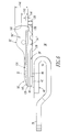
- FIG. 1 shows a movable contact arm 2 as employed in a molded case circuit breaker (MCCB) 4.
- a contact assembly 6 for the MCCB 4 includes a line conductor 8 having a folded back fixed contact end 10, a fixed contact 12 mounted on the line conductor fixed contact end 10, a movable contact 14, and the movable contact arm 2.
- the movable contact arm 2 has an inner edge 16, an outer edge 18, a first end 20 and a second end 22.
- the movable contact 14 is mounted on the first end 20.
- the movable contact arm 2 is pivotable about the second end 22 between a closed position (as shown in Figure 1) in which the inner edge 16 extends adjacent the folded back fixed contact end 10 with the movable contact 14 in electrical and mechanical contact with the fixed contact 12 to form a reverse current loop and an open position (shown in phantom line drawing in Figure 1) in which the movable contact 14 is pivoted away from the fixed contact 12.
- the movable contact arm 2 has a cross section that is narrower in width toward the outer edge 18 opposite the inner edge 16 than at the inner edge 16.
- the movable contact arm 2 is, thus, relatively narrow in cross section toward the outer edge 18. This achieves the first objective by providing relatively less material at the outer edge 18 for current to flow through, thereby forcing current down toward the inner edge 16.
- the current flowing in opposite directions in the fixed line conductor 8 and the movable contact arm 2 are closer to each other, thereby creating an increased repulsion force on the arm 2.
- This achieves the second objective by reducing the total mass that needs to be accelerated.
- the current density rises, such that the amount of tapering is limited by temperature rise restrictions and mechanical constraints.
- the movable contact arm 2 also has beveled edges 28 (only one is shown in Figure 1) on each side thereof for further weight reduction.
- the example MCCB 4 may also include a suitable narrow-channel low-profile slot motor 24 and an arc chute 26.
- Figure 2 shows a hybrid movable contact arm 32 of a contact assembly 36.
- the contact assembly 36 includes a line conductor 38 having a folded back fixed contact end 40, a fixed contact 42 mounted on the line conductor fixed contact end 40, an arc runner 43, and a movable contact 44.
- the movable contact arm 32 has an inner edge 46, an outer edge 48, a first end 50 and a second end 52.
- the movable contact 44 is mounted on the first end 50 and is pivotable about the second end 52 between a closed position (as shown in Figure 2) in which the inner edge 46 extends adjacent the folded back fixed contact end 40 with the movable contact 44 in electrical and mechanical contact with the fixed contact 42 to form a reverse current loop 53 and an open position (shown in phantom line drawing in Figure 2) in which the movable contact 44 is pivoted away from the fixed contact 42.
- the movable contact arm 32 includes a first inner longitudinal member 54 extending along the inner edge 46 and a second outer longitudinal member 56.
- the first inner longitudinal member 54 has a higher electrical conductivity than the second outer longitudinal member 56 and the second outer longitudinal member 56 having a higher shear strength and a lower specific density than the first inner longitudinal member 54.
- the first inner or lower (with respect to Figure 2) longitudinal member 54 is made of copper and is suitably coupled to the second outer or upper (with respect to Figure 2) longitudinal member 56, which is made of aluminum or an aluminum alloy.
- the movable contact arm 32 is, thus, a two-material contact arm including an inner part (along the inner edge 46) having a relatively high electrical and thermal conductivity (e.g., without limitation, copper) and an outer part (along the outer edge 48) having a relatively high tensile and shear strength, low specific density (e.g., light weight) and relatively lower electrical conductivity (e.g., without limitation, aluminum; aluminum alloy) than the inner part.
- the fact that the outer part has a relatively lower electrical conductivity helps to push the current downward to increase the opening force.
- the first inner longitudinal member 54 does not have the beveled edges 28 ( Figure 1).
- a relatively reduced gap 57 between the reverse loop 53 and the movable contact arm 32 increases the opening velocity of the contact arm.
- any suitable relatively high tensile and shear strength, low specific density (e.g., light weight) and relatively lower electrical conductivity material may be employed.
- a suitable material made from molding plastic resin with carbon fibers may be employed.
- the first inner longitudinal member 54 of Figure 2 has a length of about 2.224 inches and a width of about 0.187 inches.
- the second outer longitudinal member 56 has a length of about 2.421 inches and a width of about 0.187 inches.
- the overall height of the movable contact arm 32 is about 0.688 inches.
- the first inner longitudinal member 54 may be suitably bonded to the second outer longitudinal member 56.
- Figures 9A and 9B show a first inner longitudinal member 54' having a tongue portion 58 being suitably coupled to a second outer longitudinal member 56' having a corresponding mating groove portion 60.
- Figure 7 shows a movable contact arm 62 in which a first inner longitudinal member 54" (e.g., made of copper) is suitably coupled to a second outer longitudinal member 56" (e.g., made of aluminum; aluminum alloy) having a recess 64 for the member 54" in which the members 54",56" are coupled by a band 66.
- a first inner longitudinal member 54" e.g., made of copper
- a second outer longitudinal member 56 e.g., made of aluminum; aluminum alloy
- Figure 3 shows a view of a conventional movable contact arm 68 and reverse loop 70 having, respectively, a movable contact 72 and a fixed contact 74.
- Figures 4A-4C show simplified views of movable contact arms 76,76',76" and a reverse loop 78.
- the movable contact arm 76 employs beveled or chamfered lower (with respect to Figure 4A) corners 80 for a reduced moment of inertia.
- the movable contact arm 76' employs beveled or chamfered lower and upper (with respect to Figure 4B) corners 80,82 for further weight reduction and for enhanced magnetic repulsion.
- the movable contact arm 76" employs relatively greater beveled or chamfered lower and upper (with respect to Figure 4C) corners 80',82' for still further weight reduction.
- the copper chamfered corners 82,82' move the average current density down toward the stationary conductor of the reverse loop 78 with respect to Figures 4B and 4C.
- the movable contact arm 76 of Figure 4A reduces contact arm mass and enhances magnetic field contact arm repulsion.
- the movable contact arms 76',76" of Figures 4B and 4C reduce contact arm mass and enhance magnetic field contact arm repulsion.
- a reduction in movable contact arm mass reduces the moment of inertia around the pivot point (not shown) of the contact arm. For example, mass reduction near the end of the contact arm (at the movable contact end) has a relatively greater effect on the moment of inertia reduction than removing the mass near the pivot point.
- a reduced moment of inertia increases the angular opening velocity for a given current.
- a reduction in the gap 84 (as shown in Figure 4C) between the reverse loop 78 and the movable contact arm 76" also increases the opening velocity of the movable contact arm.
- the movable contact arms 76',76" may further have side edges between the inner edge and the outer edge, with the side edges tapering inward toward the outer edge.
- the upper section of the contact arm may be made from a relatively stronger material, such as an aluminum alloy, than the lower section, which may be made of copper.
- an aluminum alloy has a higher resistivity than copper, thereby, forcing more of the current to pass through the lower copper member which is located in relatively closer proximity to the reverse loop.
- a height of the movable contact arm between the inner edge and the outer edge may be greater than a width of the movable contact arm at the inner edge. This also increases the strength of the movable contact arm.
- a wide range of other suitable arm geometries, especially in the lightweight reinforcing member may be employed that allow for further weight reduction (e.g., without limitation, an I-beam; holes; machined ribs; rods).
- a suitable relatively good conductive material e.g., without limitation, copper
- a suitably high strength material with reasonably good thermal properties e.g., without limitation, aluminum
- suitable example copper alloys include CDA 15500 (e.g., without limitation, temper T60), CDA 11000, CDA 10100, CDA 10200, CDA 10400, CDA 11100, CDA 11500 and CDA 12500.
- suitable aluminum alloys include 7068, 7075 (e.g., without limitation, temper T651), 6262 and 2024.
- An intermediate layer (e.g., brass) (not shown) may be advantageously employed to bridge the difference in the coefficient of thermal expansion (CTE) between the two different movable contact arm materials to prevent, for example, delamination or cracking of the interface therebetween, especially if welding or brazing is employed to join the different materials.
- the aluminum may also be plated (e.g., nickel plated), in order to improve bonding characteristics.
- CTE values in mm/mm/8C include copper (1.8), brass (2.0) and aluminum (2.3).
- Figures 5A-5D show simplified hybrid movable contact arms 86,88,90,92.
- the arm 86 employs a lower (with respect to Figure 5A) copper portion 94 and an upper (with respect to Figure 5A) aluminum or aluminum alloy portion 96.
- An aluminum alloy further reduces the mass of the movable contact arm 86 and the moment of inertia and forces current into the lower copper portion 94 for increased blow-open force.
- a suitable high yield strength aluminum alloy e.g., without limitation, a 7068, 7075 or 6262 alloy
- Such alloys also have a higher resistivity than aluminum alloy 1100 (i.e., commercially pure aluminum) which forces relatively more current through the lower copper portion 94.
- the movable contact arms 88,90,92 include first inner longitudinal members 100,102,104 and second outer longitudinal members 106,108,110, respectively.
- the first inner longitudinal members 100,102,104 have a higher electrical conductivity than the respective second outer longitudinal members 106,108,110, which have a higher shear strength than the respective first inner longitudinal members 100,102,104.
- the first inner longitudinal members 100,102,104 are made of copper.
- the second outer longitudinal members 106,108,110 are made of aluminum or an aluminum alloy.
- One or both of the first inner longitudinal members 100,102,104 and the second outer longitudinal members 106,108,110 have a cross section including a height and a width, with the height being greater than the width. This improves the strength of the movable contact arms 88,90,92.
- the second outer longitudinal members 108,110 have side edges 112,114 that taper inward toward the outer edges 116,118, respectively.
- the second outer longitudinal members 108,110 are narrower at the outer edges 116,118 than at the edges 120,122 facing the first inner longitudinal members 102,104, respectively.
- Figure 6 shows another hybrid movable contact arm 32' of a contact assembly 36', which is somewhat similar to the contact assembly 36 of Figure 2.
- the movable contact arm 32 of Figure 2 is shown in phantom line drawing.
- the movable contact arm 32' has two 45° beveled portions 28' (only one beveled portion is shown) on each side for weight reduction.
- the movable contact arm 32' includes a first inner copper longitudinal member 54''' extending along inner edge 46' and a second outer aluminum or aluminum alloy longitudinal member 56'''.
- the second outer longitudinal member 56''' has an increased thickness at the nose end 50' for added strength.
- the second outer longitudinal member 56 of Figure 2 has beveled edges 124 (only one edge is shown in phantom line drawing in Figure 6) for reduced weight.
- the first inner longitudinal member 54''' has a tip portion 126, which extends past the end of the second outer longitudinal member 56''', for preventing melting of the aluminum, from the arc, during interruption.
- the thickness and the profile of the movable contact arm 32 of Figure 2 are increased for added strength to prevent bending, especially at short-circuit currents above 100 kA where even faster opening velocities and forces are expected.
- Figures 8A and 8B show another hybrid movable contact arm 32", which is somewhat similar to the movable contact arm 32' of Figure 6.
- the movable contact arm 32" has one 45° beveled portion 128 (as best shown in Figure 8B) on the top side of the second outer aluminum or aluminum alloy longitudinal member 56"" for weight reduction.
- the movable contact arm 32" also includes a first inner copper longitudinal member 54"" having a portion 129 to which a suitable shunt (not shown) for a line terminal (not shown) is electrically connected.
- Figure 10 shows another hybrid movable contact arm 130 including a first inner copper longitudinal member 132 and a second outer aluminum or aluminum alloy longitudinal member 134 having an inverted T-shaped cross section. This reduces the weight, but suitably maintains the relative strength of the second outer member 134.
- the ratio of copper-to-aluminum may be about 2:1 by weight.
- the maximum height 136 of the first inner longitudinal member 54 may be about 0.1767 inches, with an average height 138 of about 0.1446 inches with respect to surface 139.
- the maximum height 140 of the second outer longitudinal member 56 may be about 0.5109 inches, with an average height 142 of about 0.2420 inches with respect to point 143, and with a minimum height 144 of about 0.0861 inches with respect to end 145.
- the disclosed movable contact arms 2,32,32',32",62,76,76',76",86,88, 90,92,130 provide increased contact arm velocity by reducing the mass of the movable contact arm and by increasing the magnetic field "seen" by the movable contact arm. This may be achieved by combining a suitable relatively lightweight, yet relatively strong, material with a suitable current-carrying material in order to produce a hybrid, two-material contact arm. This may also be achieved by suitably shaping and profiling a movable contact arm, which may be made of one or more materials. These geometries allow for low-cost, mass production quantities suitable for MCCBs while still maintaining desirable current carrying, thermal, and interruption properties.
- the disclosed movable contact arms may readily be incorporated into existing circuit breakers without any changes to existing moldings or to the operating mechanisms. Mold changes and operating mechanism changes are very costly especially after high volume production has begun.
Landscapes
- Engineering & Computer Science (AREA)
- Manufacturing & Machinery (AREA)
- Breakers (AREA)
Applications Claiming Priority (1)
| Application Number | Priority Date | Filing Date | Title |
|---|---|---|---|
| US11/178,839 US7148774B1 (en) | 2005-07-11 | 2005-07-11 | Contact assembly |
Publications (2)
| Publication Number | Publication Date |
|---|---|
| EP1744341A2 true EP1744341A2 (de) | 2007-01-17 |
| EP1744341A3 EP1744341A3 (de) | 2008-01-23 |
Family
ID=37125921
Family Applications (1)
| Application Number | Title | Priority Date | Filing Date |
|---|---|---|---|
| EP06014278A Withdrawn EP1744341A3 (de) | 2005-07-11 | 2006-07-10 | Kontaktanordnung |
Country Status (3)
| Country | Link |
|---|---|
| US (1) | US7148774B1 (de) |
| EP (1) | EP1744341A3 (de) |
| CA (1) | CA2551766A1 (de) |
Families Citing this family (13)
| Publication number | Priority date | Publication date | Assignee | Title |
|---|---|---|---|---|
| US8148627B2 (en) * | 2006-08-25 | 2012-04-03 | Sunpower Corporation | Solar cell interconnect with multiple current paths |
| US8350417B1 (en) | 2007-01-30 | 2013-01-08 | Sunpower Corporation | Method and apparatus for monitoring energy consumption of a customer structure |
| US8158877B2 (en) | 2007-03-30 | 2012-04-17 | Sunpower Corporation | Localized power point optimizer for solar cell installations |
| DE102007040171A1 (de) | 2007-08-22 | 2009-02-26 | Siemens Ag | Kontakthebel für einen Leistungsschalter |
| US8426974B2 (en) | 2010-09-29 | 2013-04-23 | Sunpower Corporation | Interconnect for an optoelectronic device |
| US8963029B2 (en) | 2012-12-03 | 2015-02-24 | Eaton Corporation | Electrical switching apparatus and conductor assembly therefor |
| US9147531B2 (en) * | 2012-12-03 | 2015-09-29 | Eaton Corporation | Electrical switching apparatus and movable contact arm assembly therefor |
| US9000316B2 (en) | 2013-03-08 | 2015-04-07 | Eaton Corporation | Electrical switching apparatus and link assembly therefor |
| DE102013114401A1 (de) * | 2013-12-18 | 2015-06-18 | Eaton Industries Austria Gmbh | Schaltbrücke für Schaltgerät |
| US9941085B2 (en) * | 2016-01-05 | 2018-04-10 | Eaton Intelligent Power Limited | Electrical switching apparatus, and movable arm assembly and movable arm therefor |
| US10732223B2 (en) * | 2017-09-14 | 2020-08-04 | Schweitzer Engineering Laboratories, Inc. | Circuit breaker health monitoring |
| CN210956485U (zh) | 2019-12-24 | 2020-07-07 | 施耐德电器工业公司 | 分断器、分断器组件和接触器 |
| CN210897140U (zh) * | 2019-12-24 | 2020-06-30 | 施耐德电器工业公司 | 分断器和接触器 |
Citations (1)
| Publication number | Priority date | Publication date | Assignee | Title |
|---|---|---|---|---|
| DE2443771A1 (de) | 1974-04-12 | 1975-10-16 | Sace Spa | Prellsicherer grenzschalter |
Family Cites Families (9)
| Publication number | Priority date | Publication date | Assignee | Title |
|---|---|---|---|---|
| US2211412A (en) * | 1940-01-02 | 1940-08-13 | Filko John | Breaker arm for ignition devices |
| US3267243A (en) * | 1965-01-27 | 1966-08-16 | Mallory & Co Inc P R | Breaker arm assembly for a contact set |
| US3646488A (en) * | 1969-11-05 | 1972-02-29 | Tokyo Shibaura Electric Co | Electric circuit breaker |
| US4849590A (en) * | 1988-04-01 | 1989-07-18 | Kohler Company | Electric switch with counteracting electro-electro-dynamic forces |
| FR2648952B1 (fr) * | 1989-06-26 | 1991-09-13 | Merlin Gerin | Disjoncteur limiteur equipe d'un dispositif retardateur de retombee de contact a effet electromagnetique |
| US5927484A (en) | 1997-05-28 | 1999-07-27 | Eaton Corporation | Circuit breaker with welded contact interlock, gas sealing cam rider and double rate spring |
| AU6588800A (en) | 1999-08-30 | 2001-03-26 | Eaton Corporation | Circuit interrupter with crossbar having improved barrier protection |
| ITMI20012327A1 (it) * | 2001-11-06 | 2003-05-06 | Abb Service Srl | Interruttore di bassa tensione |
| US6831536B1 (en) | 2003-08-29 | 2004-12-14 | Eaton Corporation | Circuit breaker slot motor having a stepped out portion |
-
2005
- 2005-07-11 US US11/178,839 patent/US7148774B1/en not_active Expired - Fee Related
-
2006
- 2006-07-10 EP EP06014278A patent/EP1744341A3/de not_active Withdrawn
- 2006-07-11 CA CA002551766A patent/CA2551766A1/en not_active Abandoned
Patent Citations (1)
| Publication number | Priority date | Publication date | Assignee | Title |
|---|---|---|---|---|
| DE2443771A1 (de) | 1974-04-12 | 1975-10-16 | Sace Spa | Prellsicherer grenzschalter |
Also Published As
| Publication number | Publication date |
|---|---|
| CA2551766A1 (en) | 2007-01-11 |
| EP1744341A3 (de) | 2008-01-23 |
| US7148774B1 (en) | 2006-12-12 |
Similar Documents
| Publication | Publication Date | Title |
|---|---|---|
| EP1876615B1 (de) | Kontaktanordnung für eine elektrische Schaltvorrichtung sowie beweglicher Kontaktarm dafür | |
| US7148774B1 (en) | Contact assembly | |
| EP2820665B1 (de) | Schlitzmotor, schlitzmotorabdeckung, schlitzmotor -bogenplatten-anordnung und betriebsverfahren | |
| CN1298003C (zh) | 一种小型断路器 | |
| CN102110557A (zh) | 电路断路器 | |
| CN215911378U (zh) | 断路器 | |
| EP0482197A1 (de) | Ausschalter | |
| EP0284390A2 (de) | Vakuumschalter | |
| US6010059A (en) | Method for ultrasonic joining of electrical parts using a brazing alloy | |
| US6049046A (en) | Electric circuit protection device having electrical parts ultrasonically joined using a brazing alloy | |
| GB2123852A (en) | Electrode contacts for high current circuit interruption | |
| JP7031083B1 (ja) | 直流遮断器 | |
| CN217387042U (zh) | 一种用于断路器的接触组件 | |
| CN120527196B (zh) | 一种断路器引弧结构的制作方法 | |
| JPH1173860A (ja) | 接触子及びその製造方法 | |
| CN215069856U (zh) | 断路器双金构件 | |
| EP1261000B1 (de) | Elektrischer Schaltungsschutzeinrichtung mit Ultraschall geschweissten elektrische Teilen unter benützung von einer Hartlötlegierung | |
| JP2000076948A (ja) | 電気接触子 | |
| CN113496856A (zh) | 断路器 | |
| JPH0547254A (ja) | スイツチ用接点 | |
| JP2002260514A (ja) | 回路遮断器 | |
| JP5991240B2 (ja) | 接触子および電子部品 | |
| JP2001093394A (ja) | 回路遮断器 | |
| SK139599A3 (en) | Switch | |
| JP2000311535A (ja) | ガス遮断器 |
Legal Events
| Date | Code | Title | Description |
|---|---|---|---|
| PUAI | Public reference made under article 153(3) epc to a published international application that has entered the european phase |
Free format text: ORIGINAL CODE: 0009012 |
|
| AK | Designated contracting states |
Kind code of ref document: A2 Designated state(s): AT BE BG CH CY CZ DE DK EE ES FI FR GB GR HU IE IS IT LI LT LU LV MC NL PL PT RO SE SI SK TR |
|
| AX | Request for extension of the european patent |
Extension state: AL BA HR MK YU |
|
| PUAL | Search report despatched |
Free format text: ORIGINAL CODE: 0009013 |
|
| AK | Designated contracting states |
Kind code of ref document: A3 Designated state(s): AT BE BG CH CY CZ DE DK EE ES FI FR GB GR HU IE IS IT LI LT LU LV MC NL PL PT RO SE SI SK TR |
|
| AX | Request for extension of the european patent |
Extension state: AL BA HR MK YU |
|
| 17P | Request for examination filed |
Effective date: 20080221 |
|
| 17Q | First examination report despatched |
Effective date: 20080508 |
|
| AKX | Designation fees paid |
Designated state(s): DE FR GB IT |
|
| STAA | Information on the status of an ep patent application or granted ep patent |
Free format text: STATUS: THE APPLICATION IS DEEMED TO BE WITHDRAWN |
|
| 18D | Application deemed to be withdrawn |
Effective date: 20100202 |