EP1744328A2 - Rare earth magnet having high strength and high electrical resistance - Google Patents
Rare earth magnet having high strength and high electrical resistance Download PDFInfo
- Publication number
- EP1744328A2 EP1744328A2 EP06011967A EP06011967A EP1744328A2 EP 1744328 A2 EP1744328 A2 EP 1744328A2 EP 06011967 A EP06011967 A EP 06011967A EP 06011967 A EP06011967 A EP 06011967A EP 1744328 A2 EP1744328 A2 EP 1744328A2
- Authority
- EP
- European Patent Office
- Prior art keywords
- rare earth
- earth magnet
- layer
- electrical resistance
- high strength
- Prior art date
- Legal status (The legal status is an assumption and is not a legal conclusion. Google has not performed a legal analysis and makes no representation as to the accuracy of the status listed.)
- Granted
Links
Images


Classifications
-
- H—ELECTRICITY
- H01—ELECTRIC ELEMENTS
- H01F—MAGNETS; INDUCTANCES; TRANSFORMERS; SELECTION OF MATERIALS FOR THEIR MAGNETIC PROPERTIES
- H01F1/00—Magnets or magnetic bodies characterised by the magnetic materials therefor; Selection of materials for their magnetic properties
- H01F1/01—Magnets or magnetic bodies characterised by the magnetic materials therefor; Selection of materials for their magnetic properties of inorganic materials
- H01F1/03—Magnets or magnetic bodies characterised by the magnetic materials therefor; Selection of materials for their magnetic properties of inorganic materials characterised by their coercivity
- H01F1/032—Magnets or magnetic bodies characterised by the magnetic materials therefor; Selection of materials for their magnetic properties of inorganic materials characterised by their coercivity of hard-magnetic materials
- H01F1/04—Magnets or magnetic bodies characterised by the magnetic materials therefor; Selection of materials for their magnetic properties of inorganic materials characterised by their coercivity of hard-magnetic materials metals or alloys
- H01F1/047—Alloys characterised by their composition
- H01F1/053—Alloys characterised by their composition containing rare earth metals
- H01F1/055—Alloys characterised by their composition containing rare earth metals and magnetic transition metals, e.g. SmCo5
- H01F1/057—Alloys characterised by their composition containing rare earth metals and magnetic transition metals, e.g. SmCo5 and IIIa elements, e.g. Nd2Fe14B
- H01F1/0571—Alloys characterised by their composition containing rare earth metals and magnetic transition metals, e.g. SmCo5 and IIIa elements, e.g. Nd2Fe14B in the form of particles, e.g. rapid quenched powders or ribbon flakes
- H01F1/0572—Alloys characterised by their composition containing rare earth metals and magnetic transition metals, e.g. SmCo5 and IIIa elements, e.g. Nd2Fe14B in the form of particles, e.g. rapid quenched powders or ribbon flakes with a protective layer
-
- C—CHEMISTRY; METALLURGY
- C22—METALLURGY; FERROUS OR NON-FERROUS ALLOYS; TREATMENT OF ALLOYS OR NON-FERROUS METALS
- C22C—ALLOYS
- C22C38/00—Ferrous alloys, e.g. steel alloys
- C22C38/005—Ferrous alloys, e.g. steel alloys containing rare earths, i.e. Sc, Y, Lanthanides
-
- C—CHEMISTRY; METALLURGY
- C22—METALLURGY; FERROUS OR NON-FERROUS ALLOYS; TREATMENT OF ALLOYS OR NON-FERROUS METALS
- C22C—ALLOYS
- C22C38/00—Ferrous alloys, e.g. steel alloys
- C22C38/10—Ferrous alloys, e.g. steel alloys containing cobalt
-
- H—ELECTRICITY
- H01—ELECTRIC ELEMENTS
- H01F—MAGNETS; INDUCTANCES; TRANSFORMERS; SELECTION OF MATERIALS FOR THEIR MAGNETIC PROPERTIES
- H01F10/00—Thin magnetic films, e.g. of one-domain structure
- H01F10/08—Thin magnetic films, e.g. of one-domain structure characterised by magnetic layers
- H01F10/10—Thin magnetic films, e.g. of one-domain structure characterised by magnetic layers characterised by the composition
- H01F10/12—Thin magnetic films, e.g. of one-domain structure characterised by magnetic layers characterised by the composition being metals or alloys
- H01F10/126—Thin magnetic films, e.g. of one-domain structure characterised by magnetic layers characterised by the composition being metals or alloys containing rare earth metals
-
- H—ELECTRICITY
- H01—ELECTRIC ELEMENTS
- H01F—MAGNETS; INDUCTANCES; TRANSFORMERS; SELECTION OF MATERIALS FOR THEIR MAGNETIC PROPERTIES
- H01F1/00—Magnets or magnetic bodies characterised by the magnetic materials therefor; Selection of materials for their magnetic properties
- H01F1/01—Magnets or magnetic bodies characterised by the magnetic materials therefor; Selection of materials for their magnetic properties of inorganic materials
- H01F1/03—Magnets or magnetic bodies characterised by the magnetic materials therefor; Selection of materials for their magnetic properties of inorganic materials characterised by their coercivity
- H01F1/032—Magnets or magnetic bodies characterised by the magnetic materials therefor; Selection of materials for their magnetic properties of inorganic materials characterised by their coercivity of hard-magnetic materials
- H01F1/04—Magnets or magnetic bodies characterised by the magnetic materials therefor; Selection of materials for their magnetic properties of inorganic materials characterised by their coercivity of hard-magnetic materials metals or alloys
- H01F1/047—Alloys characterised by their composition
- H01F1/053—Alloys characterised by their composition containing rare earth metals
- H01F1/055—Alloys characterised by their composition containing rare earth metals and magnetic transition metals, e.g. SmCo5
- H01F1/057—Alloys characterised by their composition containing rare earth metals and magnetic transition metals, e.g. SmCo5 and IIIa elements, e.g. Nd2Fe14B
- H01F1/0571—Alloys characterised by their composition containing rare earth metals and magnetic transition metals, e.g. SmCo5 and IIIa elements, e.g. Nd2Fe14B in the form of particles, e.g. rapid quenched powders or ribbon flakes
- H01F1/0573—Alloys characterised by their composition containing rare earth metals and magnetic transition metals, e.g. SmCo5 and IIIa elements, e.g. Nd2Fe14B in the form of particles, e.g. rapid quenched powders or ribbon flakes obtained by reduction or by hydrogen decrepitation or embrittlement
-
- H—ELECTRICITY
- H01—ELECTRIC ELEMENTS
- H01F—MAGNETS; INDUCTANCES; TRANSFORMERS; SELECTION OF MATERIALS FOR THEIR MAGNETIC PROPERTIES
- H01F41/00—Apparatus or processes specially adapted for manufacturing or assembling magnets, inductances or transformers; Apparatus or processes specially adapted for manufacturing materials characterised by their magnetic properties
- H01F41/02—Apparatus or processes specially adapted for manufacturing or assembling magnets, inductances or transformers; Apparatus or processes specially adapted for manufacturing materials characterised by their magnetic properties for manufacturing cores, coils, or magnets
- H01F41/0253—Apparatus or processes specially adapted for manufacturing or assembling magnets, inductances or transformers; Apparatus or processes specially adapted for manufacturing materials characterised by their magnetic properties for manufacturing cores, coils, or magnets for manufacturing permanent magnets
- H01F41/0266—Moulding; Pressing
-
- Y—GENERAL TAGGING OF NEW TECHNOLOGICAL DEVELOPMENTS; GENERAL TAGGING OF CROSS-SECTIONAL TECHNOLOGIES SPANNING OVER SEVERAL SECTIONS OF THE IPC; TECHNICAL SUBJECTS COVERED BY FORMER USPC CROSS-REFERENCE ART COLLECTIONS [XRACs] AND DIGESTS
- Y10—TECHNICAL SUBJECTS COVERED BY FORMER USPC
- Y10T—TECHNICAL SUBJECTS COVERED BY FORMER US CLASSIFICATION
- Y10T428/00—Stock material or miscellaneous articles
- Y10T428/32—Composite [nonstructural laminate] of inorganic material having metal-compound-containing layer and having defined magnetic layer
-
- Y—GENERAL TAGGING OF NEW TECHNOLOGICAL DEVELOPMENTS; GENERAL TAGGING OF CROSS-SECTIONAL TECHNOLOGIES SPANNING OVER SEVERAL SECTIONS OF THE IPC; TECHNICAL SUBJECTS COVERED BY FORMER USPC CROSS-REFERENCE ART COLLECTIONS [XRACs] AND DIGESTS
- Y10—TECHNICAL SUBJECTS COVERED BY FORMER USPC
- Y10T—TECHNICAL SUBJECTS COVERED BY FORMER US CLASSIFICATION
- Y10T428/00—Stock material or miscellaneous articles
- Y10T428/32—Composite [nonstructural laminate] of inorganic material having metal-compound-containing layer and having defined magnetic layer
- Y10T428/325—Magnetic layer next to second metal compound-containing layer
Definitions
- the present invention relates to a rare earth magnet having high strength and high electrical resistance.
- Priority is claimed on Japanese Patent Application Nos. 2005-170475, filed on June 10, 2005 , 2005-170476, filed on June 10, 2005 , and 2005-170477, filed on June 10, 2005 , the contents of which are incorporated herein by reference.
- R-Fe-B-based rare earth magnet where R represents one or more kind of rare earth element including Y (this applies throughout this application), is known to have such a composition that contains R, Fe and B as basic components with Co and/or M (M represents one or more kind selected from among Ga, Zr, Nb, Mo, Hf, Ta, W, Ni, Al, Ti, V, Cu, Cr, Ge, C and Si; this applies throughout this application) added as required, specifically, 5 to 20% of R, 0 to 50% of Co, 3 to 20% of B and 0 to 5% of M are contained (% refers to atomic %, which applies throughout this application), with the balance consisting of Fe and inevitable impurities.
- M represents one or more kind selected from among Ga, Zr, Nb, Mo, Hf, Ta, W, Ni, Al, Ti, V, Cu, Cr, Ge, C and Si; this applies throughout this application
- M represents one or more kind selected from among Ga, Zr, Nb, Mo, Hf, Ta, W, Ni, Al, Ti
- the R-Fe-B-based rare earth magnet can be manufactured by subjecting an R-Fe-B-based rare earth magnet powder to hot pressing, hot isostatic pressing or the like.
- One of methods of manufacturing the R-Fe-B-based rare earth magnet powder is such that an R-Fe-B-based rare earth magnet alloy material that has been subjected to hydrogen absorption treatment is heated to a temperature in a range from 500 to 1000°C and kept at this temperature in hydrogen atmosphere of pressure from 10 to 1000 kPa so as to carry out hydrogen absorption and decomposition treatment in which the R-Fe-B-based rare earth magnet alloy material is caused to absorb hydrogen and decompose through phase transition, followed by dehydrogenation of the R-Fe-B-based rare earth magnet alloy material by holding the R-Fe-B-based rare earth magnet alloy material in vacuum at a temperature in a range from 500 to 1000°C.
- the R-Fe-B-based rare earth magnet powder thus obtained has recrystallization texture consisting of adjoining recrystallized grains that are constituted from R 2 Fe 14 B type intermetallic compound phase that has substantially tetragonal structure as the main phase, and the recrystallization texture has the fundamental structure of magnetically anisotropic HDDR magnetic powder in which the fundamental structure has such a constitution that 50% by volume or more of the recrystallized grains are those which have such a shape as the ratio b/a of the least grain size a and the largest grain size b of the recrystallized grains is less than 2, and average size of the recrystallized grains is in a range from 0.05 to 5 ⁇ m ( Japanese Patent No. 2,376,642 ).
- R-Fe-B-based rare earth magnets that have high electrical resistance have been developed. It has been proposed to make one of these R-Fe-B-based rare earth magnets that have high electrical resistance by forming an R oxide layer in the grain boundary of R-Fe-B-based rare earth magnet particles so that the R-Fe-B-based rare earth magnet particles are enclosed with the R oxide layer to make a structure ( Japanese Unexamined Patent Application, First Publication No. 2004-31780 and Japanese Unexamined Patent Application, First Publication No. 2004-31781 ).
- the rare earth magnet of the prior art that has high electrical resistance has a structure such that the R oxide layer exists in the grain boundary of the R-Fe-B-based rare earth magnet particles, bonding strength between the R-Fe-B-based rare earth magnet particles is weak, and therefore, the rare earth magnet of the prior art that has high electrical resistance has the problem of insufficient mechanical strength.
- the present inventors conducted a research to make a rare earth magnet that has further higher strength and higher electrical resistance. It was found that satisfactory magnetic anisotropy and coercivity comparable to those of the conventional rare earth magnet and further higher strength and higher electrical resistance can be achieved with a rare earth magnet that is formed by stacking a composite layer which has high strength and high electrical resistance (hereinafter referred to as high strength and high electrical resistance composite layer) and an R-Fe-B-based rare earth magnet layer, wherein the high strength and high electrical resistance composite layer comprises a glass-based layer having a glass phase or a structure of R oxide particles dispersed in glass phase, and an R oxide particle-based mixture layers that are formed on both sides of the glass-based layer and contain an R-rich alloy phase which contains 50 atomic % or more of R in the grain boundary of the R oxide particles.
- high strength and high electrical resistance composite layer comprises a glass-based layer having a glass phase or a structure of R oxide particles dispersed in glass phase, and an R oxide particle-based mixture layers that are formed
- the present invention is based on the results of the research described above, and is characterized as:
- the glass-based layer in the high strength and high electrical resistance composite layer improves the insulation performance and increases the strength of bonding with the R oxide particle-based mixture layer.
- the R oxide particle-based mixture layer prevents the R-Fe-B-based rare earth magnet layer and the glass-based layer from reacting with each other, so that the magnetic property is prevented from decreasing and bonding strength is increased, thereby making rare earth magnet having high strength and high electrical resistance that is excellent also in magnetic property.
- Presence of the high strength and high electrical resistance composite layer enables the rare earth magnet having high strength and high electrical resistance of the present invention to greatly improve the electrical resistance inside of the magnet so as to reduce the eddy current generated therein and thereby suppress the heat generation from the magnet significantly.
- the present invention may also have such a constitution as:
- the present inventors also conducted a research to make a rare earth magnet having further higher strength and higher electrical resistance. It was found that satisfactory magnetic anisotropy and coercivity comparable to those of the conventional rare earth magnet and further higher strength and higher electrical resistance can be achieved with a rare earth magnet that has a structure such that the R-Fe-B-based rare earth magnet particles are enclosed with the composite layer having high strength and high electrical resistance, wherein the high strength and high electrical resistance composite layer comprises a glass-based layer having a glass phase or a structure of R oxide particles dispersed in glass phase, and R oxide particle-based mixture layers that are formed on both sides of the glass-based layer and contain an R-rich alloy phase which contains 50 atomic % or more of R in the grain boundary of the R oxide particles.
- the present invention is based on the results of the research described above, and is characterized as:
- the glass-based layer provided in the high strength and high electrical resistance composite layer further improves the insulation performance and increases the strength of bonding with the R oxide particle-based mixture layer.
- the R oxide particle-based mixture layers prevent the R-Fe-B-based rare earth magnet particles and the glass-based layer from reacting with each other, so that the magnetic property is prevented from decreasing and bonding strength is increased, thereby making rare earth magnet having high strength and high electrical resistance that is excellent also in magnetic property.
- Presence of the high strength and high electrical resistance composite layer enables the rare earth magnet having high strength and high electrical resistance of the present invention to greatly improve the electrical resistance inside of the magnet so as reduce the eddy current generated therein and thereby suppress the heat generation from the magnet significantly.
- the present invention may also have such a constitution as:
- the present inventors also conducted a research to make a rare earth magnet having further higher strength and higher electrical resistance. It was found that higher strength and higher electrical resistance than those of a conventional rare earth magnet of high electrical resistance, which have such a constitution as an R oxide layer is formed in the grain boundary of the R-Fe-B-based rare earth magnet particles so that the R-Fe-B-based rare earth magnet particles are enclosed with the R oxide layer, can be achieved with a rare earth magnet formed by stacking a composite layer having high strength and high electrical resistance (hereinafter referred to as the high strength and high electrical resistance composite layer) constituted from two oxide layers of R (R represents one or more kind of rare earth elements including Y; this applies throughout this application) that sandwich one glass layer and an R-Fe-B-based rare earth magnet layer, wherein the high strength and high electrical resistance composite layer is provided between the R-Fe-B-based rare earth magnet layers.
- the present invention is based on the results of the research described above, and is characterized as:
- the glass layer provided in the high strength and high electrical resistance composite layer increases the bonding strength between the R oxide layers, thus resulting in higher mechanical strength of the rare earth magnet, higher insulation and high strength and high electrical resistance.
- presence of the high strength and high electrical resistance composite layer enables the rare earth magnet having high strength and high electrical resistance of the present invention to greatly improve the electrical resistance inside of the magnet so as reduce the eddy current generated therein and thereby suppress the heat generation from the magnet significantly.
- the present invention may also have such a constitution as:
- the present inventors further conducted a research to make a rare earth magnet having further higher strength and higher electrical resistance. It was found that satisfactory magnetic anisotropy and coercivity comparable to those of the conventional rare earth magnet and further higher strength and higher electrical resistance can be achieved with a rare earth magnet having a structure having the R-Fe-B-based rare earth magnet particles which are enclosed with the high strength and high electrical resistance composite layer formed by stacking the R oxide layers on both sides of the glass layer in contact therewith.
- the present invention is based on the results of the research described above, and is characterized as:
- the rare earth magnet having high strength and high electrical resistance of the present invention comprises the R-Fe-B-based rare earth magnet particles and the high strength and high electrical resistance composite layer having the R oxide layer formed in the grain boundaries of the R-Fe-B-based rare earth magnet particles and the glass layer, in which the R-Fe-B-based rare earth magnet particles have a structure that are enclosed with the high strength and high electrical resistance composite layer that is provided in the grain boundary of the R-Fe-B-based rare earth magnet particles. Presence of the glass layer in the high strength and high electrical resistance composite layer enables bonding strength between the R oxide layer to increase, thus resulting in greatly increased mechanical strength of the rare earth magnet, higher insulation and high strength and high electrical resistance.
- presence of the high strength and high electrical resistance composite layer enables the rare earth magnet having high strength and high electrical resistance of the present invention to greatly improve the electrical resistance inside of the magnet so as reduce the eddy current generated therein and thereby suppress the heat generation from the magnet significantly.
- the present invention may also have such a constitution as:
- the rare earth magnet having high strength and high electrical resistance of the present invention is capable of enduring severe vibration because of the high strength, and makes it possible to improve the performance of a permanent magnet motor that incorporates the rare earth magnet having high strength and high electrical resistance.
- Fig. 1 is a schematic diagram showing a cross section of the rare earth magnet having high strength and high electrical resistance described in (1).
- a rare earth magnet 1 comprises an R-Fe-B-based rare earth magnet layer 11, a high strength and high electrical resistance composite layer 12, R oxide particles 13, an R-rich alloy phase 14, a glass phase 15, a glass-based layer 16, and an R oxide particle-based mixture layer 17.
- the high strength and high electrical resistance composite layer 12 has a structure such that the R oxide particle-based mixture layers 17 are formed on both sides of the glass-based layer I6 in contact therewith, while the high strength and high electrical resistance composite layer 12 is provided between the R-Fe-B-based rare earth magnet layers 11.
- the glass-based layer 16 has a structure consisting of a glass phase only or the R oxide particles 13 dispersed in the glass phase 15, and the R oxide particle-based mixture layer 17 contains the R-rich alloy phase 14 which contains 50 atomic % or more of R in the grain boundary of the R oxide particles 13.
- the high strength and high electrical resistance composite layer 12 has further improved insulation property due to the glass-based layer 16 and increased bonding strength with the R oxide particle-based mixture layer 17.
- the R oxide particle-based mixture layer 17 prevents the R-Fe-B-based rare earth magnet layer 11 and the glass-based layer 16 from reacting with each other, prevents the magnetic property from decreasing and increases the bonding strength, thereby making the rare earth magnet having high strength and high electrical resistance that is excellent also in magnetic property.
- Presence of the high strength and high electrical resistance composite layer 12 enables the rare earth magnet 1 having high strength and high electrical resistance of the present invention to greatly improve the electrical resistance inside of the magnet 1 so as reduce the eddy current generated therein and thereby suppress the heat generation from the magnet significantly.
- the rare earth magnet having a constitution of one high strength and high electrical resistance composite layer 12 being provided between two R-Fe-B-based rare earth magnet layers 11 is shown in Fig. 1 to make the invention easier to understand, the rare earth magnet having high strength and high electrical resistance of the present invention may also have such a constitution as n pieces (n is a positive integer) of high strength and high electrical resistance composite layers 12 are provided between n+1 pieces of R-Fe-B-based rare earth magnet layers 11 alternately.
- the high strength and high electrical resistance composite layer 12 may also have an R oxide layer formed on the surface of the R oxide particle-based mixture layer 17 opposite to the surface that makes contact with the glass-based layer 16.
- Fig. 2 is a schematic sectional view of the rare earth magnet having high strength and high electrical resistance in the constitution that the high strength and high electrical resistance composite layer 12 has the R oxide layer, namely the rare earth magnet having high strength and high electrical resistance described in (2).
- the rare earth magnet 2 comprises the R-Fe-B-based rare earth magnet layer 11, the high strength and high electrical resistance composite layer 12, the R oxide particles 13, the R-rich alloy phase 14, the glass phase 15, the glass-based layer 16, the R oxide particle-based mixture layer 17, and an R oxide layer 19. As shown in Fig.
- the high strength and high electrical resistance composite layer 12 bas a structure such that the R oxide particle-based mixture layers 17 are stacked on both sides of the glass-based layer 16 in contact therewith, and has the R oxide layer 19 formed on the surface of the R oxide particle-based mixture layer 17 opposite to the surface thereof that makes contact with the glass-based layer 16, while the high strength and high electrical resistance composite layer 12 is provided between the R-Fe-B-based rare earth magnet layers 11,
- the glass-based layer 16 has a structure consisting of glass phase only or the R oxide particles 13 dispersed in the glass phase 15, and the R oxide particle-based mixture layer 17 contains an R-rich alloy phase which contains 50 atomic % or more R in the grain boundary of the R oxide particles, and the R oxide layer 19 is composed of oxide of R.
- the high strength and high electrical resistance composite layer 12 has further improved insulation property due to the glass-based layer 16 and the R oxide layer 19 and increased bonding strength with the R oxide particle-based mixture layer 17.
- the R oxide particle-based mixture layer 17 and the R oxide layer 19 prevent the R-Fe-B-based rare earth magnet layer 11 and the glass-based layer 16 from reacting with each other, prevent the magnetic property from decreasing and increase the bonding strength.
- Presence of the high strength and high electrical resistance composite layer 12 increases the strength of entire magnet so as to be capable of enduring severe vibration, and enables the rare earth magnet to greatly improve the electrical resistance of the inside of the magnet so as to reduce the eddy current generated therein, and thereby suppress the heat generation from the magnet significantly, while providing excellent magnetic property.
- the rare earth magnet having a constitution of one high strength and high electrical resistance composite layer 12 being provided between two R-Fe-B-based rare earth magnet layers 11 is shown in Fig. 2 to make the invention easier to understand, the rare earth magnet having high strength and high electrical resistance of the present invention may have a constitution such that n pieces (n is a positive integer) of high strength and high electrical resistance composite layers 12 are provided between n+1 R-Fe-B-based rare earth magnet layers 11 alternately.
- Fig. 3 is a schematic sectional view of the rare earth magnet having high strength and high electrical resistance described in (15),
- the rare earth magnet 3 comprises an R-Fe-B-based rare earth magnet layer 31, a high strength and high electrical resistance composite layer 32, an R oxide layer 33, and a glass layer 34.
- the high strength and high electrical resistance composite layer 32 has a structure such that the R oxide layers 3 are stacked on both sides of the glass layer 34 in contact therewith, and the high strength and high electrical resistance composite layer 32 is provided between the R-Fe-B-based rare earth magnet layers 31.
- the high strength and high electrical resistance composite layer 32 has a stacking structure as described above, bonding between the R oxide layers 33 is made firmer by the glass layer 34 so that strength of the rare earth magnet is greatly improved while the insulation property is improved and high strength and high electrical resistance are achieved. Also the presence of the high strength and high electrical resistance composite layer 32 enables the rare earth magnet having high strength and high electrical resistance of the present invention to greatly improve the electrical resistance inside of the magnet so as to reduce the eddy current generated therein and thereby suppress the heat generation from the magnet significantly. While the rare earth magnet having a constitution such that one high strength and high electrical resistance composite layer 32 is provided between two R-Fe-B-based rare earth magnet layers 31 in Fig.
- the rare earth magnet having high strength and high electrical resistance of the present invention may have a constitution such that n pieces (n is a positive integer) of high strength and high electrical resistance composite layer 32 are provided between n+1 R-Fe-B-based rare earth magnet layers 31 alternately.
- the R-Fe-B-based rare earth magnet layers 11 and 31 may have a composition such that 5 to 20% of R and 3 to 20% of B are contained with the balance consisting of Fe and inevitable impurities, or a composition such that 5 to 20% of R, 3 to 20% of B, and 0.001 to 5% of M are contained with the balance consisting of Fe and inevitable impurities, or a composition such that 5 to 20% of R, 0.1 to 50% of Co, and 3 to 20% of B are contained with the balance consisting of Fe and inevitable impurities, or a composition such that 5 to 20% of R, 0.1 to 50% of Co, 3 to 20% of B, and 0.001 to 5% of M are contained with the balance consisting of Fe and inevitable impurities.
- Fig. 1 shows the high strength and high electrical resistance composite layer 12 in a structure such that the R oxide particle-based mixture layers 17 are stacked on both sides of the glass-based layer 16 in contact therewith, and the high strength and high electrical resistance composite layer 12 is provided between the R-Fe-B-based rare earth magnet layers 11,11.
- the glass-based layer 16 is formed by softening and fusing the glass powder to form a glass phase or causing the R oxide particles to disperse in the softened glass phase during formation by hot pressing, and the R oxide particle-based mixture layer 17 is formed by causing the R-rich alloy phase 14 containing 50 atomic % or more of R contained in the R-Fe-B-based rare earth magnet layer 11 to enter the grain boundary between the R oxide particles 13 during formation by hot pressing.
- R of the R oxide particles 13 that constitute the high strength and high electrical resistance composite layer 12 may or may not be the same R contained in the R-Fe-B-based rare earth magnet layer 11, it is preferably one or more kind selected from among Y, Gd, Tb, Dy, Ho, Er, Tm, Yb and Lu, and is more preferably Tb and/or Dy.
- Fig. 2 shows the high strength and high electrical resistance composite layer 12 which is formed by stacking the R oxide particle-based mixture layers 17 on both sides of the glass-based layer 16 in contact therewith and further has the R oxide layer 19 formed on the surface of the R oxide particle-based mixture layer 17 opposite to the surface that makes contact with the glass-based layer 16, while the high strength and high electrical resistance composite layer 12 is provided between the R-Fe-B-based rare earth magnet layers 11, 11.
- the glass-based layer 16 is formed by softening and fusing the glass powder to form a glass phase or causing the R oxide particles to disperse in the softened glass phase during formation by hot pressing, and the R oxide particle-based mixture layer 17 is formed by causing the R-rich alloy phase 14 containing 50 atomic % or more of R contained in the R-Fe-B-based rare earth magnet layer 11, to enter the grain boundary of the R oxide particles 13 during formation by hot pressing.
- the R oxide particle-based mixture layer 17 is formed as the R-rich alloy phase 14 which contains 50 atomic % or more R contained in the R-Fe-B-based rare earth magnet layer 11 enters through a portion of the R oxide layer 19 where it is cracked or peeled off into the grain boundary of the R oxide particles 13 during formation by hot pressing or the like.
- R of the R oxide particles 13 and of the R oxide layer 19 that constitute the high strength and high electrical resistance composite layer 12 may or may not be the same R contained in the R-Fe-B-based rare earth magnet layer 11, it is preferably one or more kind selected from the group consisting of Y, Gd, Tb, Dy, Ho, Er, Tm, Yb, and Lu, and is more preferably Tb and/or Dy.
- R of the R-rich alloy phase 14 is preferably the same as the R contained in the R-Fe-B-based rare earth magnet layer 11, but may be different from the R contained in the R-Fe-B-based rare earth magnet layer 11.
- R of the R oxide layer 33 that constitutes the high strength and high electrical resistance composite layer 32 may or may not be the same as the R contained in the R-Fe-B-based rare earth magnet layer 31, it is preferably one or more kind selected from among Y, Gd, Tb, Dy, Ho, Er, Tm, Yb, and Lu, and is more preferably Tb and/or Dy.
- the R-Fe-B-based rare earth magnet layers 11 and 31 are more preferably magnetically anisotropic HDDR magnetic layers having a recrystallization texture consisting of adjoining recrystallized grains that are constituted from an R 2 Fe 14 B type intermetallic compound phase of a substantially tetragonal structure as the main phase, while the recrystallization texture has a fundamental structure containing 50% by volume or more of the recrystallized grains having a shape such that the ratio b/a of the minimum grain size a and the maximum grain size b of the recrystallized grain is less than 2, and the average size of the recrystallized grains is in a range from 0.05 to 5 ⁇ m.
- An example of manufacturing the rare earth magnet having high strength and high electrical resistance of the present invention shown in Fig. 1 is as follows.
- An R-Fe-B-based rare earth magnet powder green compact layer is formed from an ordinary R-Fe-B-based rare earth magnet powder that has high magnetic anisotropy by a forming process in magnetic field.
- An R oxide particle slurry is applied onto the upper and lower surfaces or the upper surface of the R-Fe-B-based rare earth magnet powder green compact layer by spin coating method or the like so as to form an R oxide particle slurry layer.
- the R oxide particle slurry layer is then coated with a slurry of glass powder or a mixed powder, consisting of glass powder as the main component with the addition of R oxide powder (hereinafter referred to as glass-based powder), by spin coating method or the like so as to form a glass-based powder slurry layer.
- a slurry of glass powder or a mixed powder consisting of glass powder as the main component with the addition of R oxide powder (hereinafter referred to as glass-based powder)
- glass-based powder R-Fe-B-based rare earth magnet green compact layer prepared by coating the glass-based powder slurry layer with the R oxide particle slurry is provided to face the R oxide particle slurry layer, thereby to make a stacked green compact.
- the hot-pressed material thus obtained is constituted from the high strength and high electrical resistance composite layer 12 and the R-Fe-B-based rare earth magnet layer 11 stacked one on another as shown in Fig. 1.
- the high strength and high electrical resistance composite layer 12 has a structure such that the R oxide particle-based mixture layers 17 are stacked on both sides of the glass-based layer 16 in contact therewith, where the glass-based layer 16 is formed by softening and fusing the glass powder to form glass phase or causing the R oxide particles to disperse in the softened glass phase during the hot pressing process, and the R oxide particle-based mixture layer 17 is formed by causing the R-rich alloy phase, which contains 50 atomic % or more of R contained in the R-Fe-B-based rare earth magnet layer 11, to enter the grain boundary of the R oxide particles during the hot pressing process.
- An example of manufacturing the rare earth magnet having high strength and high electrical resistance of the present invention shown in Fig. 2 is as follows.
- An R-Fe-B-based rare earth magnet powder green compact layer is formed from an ordinary R-Fe-B-based rare earth magnet powder that has high magnetic anisotropy by a forming process in magnetic field.
- a sputtered layer of R oxide is formed on the surface of the R-Fe-B-based rare earth magnet powder green compact layer, and the sputtered layer of R oxide is coated with an R oxide particle slurry by spin coating method or the like, which is then dried so as to form an R oxide particle slurry layer.
- the R oxide particle slurry layer is then coated with a slurry of glass powder so as to form a glass powder slurry layer.
- Another R-Fe-B-based rare earth magnet powder green compact layer prepared by coating the glass-based powder slurry layer with the R oxide particle slurry layer is provided to face the R oxide particle slurry layer, thereby to make a stacked green compact.
- the rare earth magnet having high strength and high electrical resistance of the present invention shown in Fig. 2 is obtained.
- the hot-pressed material thus obtained is constituted from the high strength and high electrical resistance composite layer 12 and the R-Fe-B-based rare earth magnet layer 11 stacked one on another, similarly to the rare earth magnet having high strength and high electrical resistance shown in Fig. I.
- the high strength and high electrical resistance composite layer 12 has a structure such that the R oxide particle-based mixture layers 17 are stacked on both sides of the glass-based layer 16 in contact therewith, where the glass-based layer 16 is formed by softening and fusing the glass powder to form the glass phase or causing the R oxide particles to disperse in the softened glass phase during the hot pressing process, and the R oxide particle-based mixture layer 17 is formed by causing the R-rich alloy phase, which contains 50 atomic % or more ofR contained in the R-Fe-B-based rare earth magnet layer 11, to enter the grain boundary of the R oxide particles during the hot pressing process.
- An R-Fe-B-based rare earth magnet powder green compact layer is formed from an ordinary R-Fe-B-based rare earth magnet powder that has high magnetic anisotropy by a forming process in magnetic field.
- a sputtered layer of oxide of rare earth element is formed on the upper and lower surfaces or the upper surface of the R-Fe-B-based rare earth magnet powder green compact layer, so as to make at least two stacked bodies constituted from the R-Fe-B-based rare earth magnet powder green compact layer and the R oxide layer.
- These stacked bodies are placed one on another so as to provide the glass powder layer between the R oxide layers, thereby to form a stacked green compact constituted from the R-Fe-B-based rare earth magnet powder green compact layer, the R oxide layer, the glass powder layer, the R oxide layer, and the R-Fe-B-based rare earth magnet powder green compact layer in order.
- a stacked green compact constituted from the R-Fe-B-based rare earth magnet powder green compact layer, the R oxide layer, the glass powder layer, the R oxide layer, and the R-Fe-B-based rare earth magnet powder green compact layer in order.
- the hot-pressed material thus obtained is constituted from the R-Fe-B-based rare earth magnet layers 31 and the high strength and high electrical resistance composite layer 32 that comprises the R oxide layers 33, 33 and the glass layer 34 stacked one on another, as shown in Fig. 3.
- the high strength and high electrical resistance composite layer 32 has the structure of interposing the glass layer 34 by the R oxide layers 33, 33. Since the high strength and high electrical resistance composite layer 32 has high strength and high electrical resistance, the rare earth magnet having high strength and high electrical resistance can be formed by providing the high strength and high electrical resistance composite layer 32 between the R-Fe-B-based rare earth magnet layers 31.
- the glass layer of the high strength and high electrical resistance composite layer that constitutes the rare earth magnet having high strength and high electrical resistance may be any glass that is used in low temperature sintering of ceramics, such as SiO 2 -B 2 O 3 -Al 2 O 3 ⁇ based glass, SiO 2 -BaO-Al 2 O 3 ⁇ based glass, SiO 2 -BaO-B 2 O 3 ⁇ based glass, SiO 2 -BaO-Li 2 O 3 ⁇ based glass, SiO 2 -B 2 O 3 -RrO ⁇ based glass (RrO represents an oxide of an alkaline earth metal), SiO 2 -ZnO-RrO ⁇ based glass, SiO 2 -MgO-Al 2 O 3 ⁇ based glass, SiO 2 -B 2 O 3 -ZnO ⁇ based glass, B 2 O 3 -ZnO ⁇ based glass or SiO 2 -Al 2 O 3 -RrO ⁇ based glass.
- ceramics such as SiO 2 -B 2
- glass having low softening point may also be used such as PbO-B 2 O 3 ⁇ based glass, SiO 2 -B 2 O 3 -PbO ⁇ based glass, Al 2 O 3 -B 2 O 3 -PbO ⁇ based glass, Sn-P 2 O 5 ⁇ based glass, ZnO-P 2 O 5 ⁇ based glass, CuO-P 2 O 5 ⁇ based glass or SiO 2 -B 2 O 3 -ZnO ⁇ based glass. It is preferable to use a glass that has softening point in a temperature range in which the hot pressing is carried out: from 500 to 900°C.
- Fig. 4 is a schematic sectional view of the rare earth magnet having high strength and high electrical resistance described in (8).
- components other than R-Fe-B-based rare earth magnet particles 18 are the same as those of the rare earth magnet 1 shown in Fig. 1, and will be omitted in the description that follows.
- the rare earth magnet 4 having high strength and high electrical resistance of the present invention shown in Fig. 4 has a structure such that the high strength and high electrical resistance composite layer 12 is provided in the grain boundaries between the R-Fe-B-based rare earth magnet particle 18 and the R-Fe-B-based rare earth magnet particle 18, so that the R-Fe-B-based rare earth magnet particles 18 are enclosed with the high strength and high electrical resistance composite layer 12.
- the glass-based layer 16 of the high strength and high electrical resistance composite layer 12 further improves the insulation property, and also makes the bonding with the R oxide particle-based mixture layer 17 stronger.
- the R oxide particle-based mixture layer 17 prevents the R-Fe-B-based rare earth magnet particles 18 and the glass-based layer 16 from reacting with each other, so that the magnetic property is prevented from decreasing and bonding strength is increased, thereby providing the rare earth magnet having high strength and high electrical resistance that is excellent also in magnetic property.
- Presence of the high strength and high electrical resistance composite layer 12 enables the rare earth magnet having high strength and high electrical resistance of the present invention to greatly improve the electrical resistance inside of the magnet so as to reduce the eddy current generated therein and thereby suppress the heat generation from the magnet significantly.
- the high strength and high electrical resistance composite layer 12 may also include an R oxide layer formed on the surface of the R oxide particle-based mixture layer 17 opposite to the surface thereof that makes contact with the glass-based layer 16.
- Fig. 5 is a schematic sectional view showing the rare earth magnet having high strength and high electrical resistance in the constitution that the rare earth magnet having high strength and high electrical resistance described in (8) has the R oxide layer, namely the rare earth magnet having high strength and high electrical resistance described in (9).
- the constitution is the same as that of the rare earth magnet 4 shown in Fig. 4 except that the high strength and high electrical resistance composite layer 12 further contains an R oxide layer 19, and will be omitted in the description that follows.
- the glass-based layer 16 and the R oxide layer 19 of the high strength and high electrical resistance composite layer 12 further improve the insulation property, and also make bonding with the R oxide particle-based mixture layer 17 stronger.
- the R oxide particle-based mixture layer 17 and the R oxide layer 19 prevent the R-Fe-B-based rare earth magnet particles 18 and the glass-based layer 16 from reacting with each other, so that the magnetic property is prevented from decreasing and bonding strength is increased.
- Presence of the high strength and high electrical resistance composite layer 12 increases the strength of the magnet as a whole and enables the magnet to endure severe vibration, greatly improve the electrical resistance inside of the magnet so as to reduce the eddy current generated therein and thereby suppress the heat generation from the magnet significantly, and make the rare earth magnet excellent also in the magnet property.
- Fig. 6 is a schematic sectional view showing the rare earth magnet having high strength and high electrical resistance described in (21).
- the constitution is the same as that of the rare earth magnet 3 shown in Fig. 3 except that R-Fe-B-based rare earth magnet particles 35 are contained, and will be omitted in the description that follows.
- the rare earth magnet having high strength and high electrical resistance of the present invention shown in Fig. 6 has a structure such as the high strength and high electrical resistance composite layer 32 constituted from the R oxide layers 33, 33 and the glass layer 34 in the grain boundary between the R-Fe-B-based rare earth magnet particles 35, and the R-Fe-B-based rare earth magnet particles 35 are enclosed with the high strength and high electrical resistance composite layer 32.
- Presence of the high strength and high electrical resistance composite layer 32 in the grain boundary between the R-Fe-B-based rare earth magnet particles 35 and the R-Fe-B-based rare earth magnet particles 35 results in stronger bonding between the R oxide layers 33 due to the glass layer 34 of the high strength and high electrical resistance composite layer 32, so that the mechanical strength of the rare earth magnet is greatly improved and insulation property is also improved, thus achieving high strength and high electrical resistance.
- Presence of the high strength and high electrical resistance composite layer 32 enables the rare earth magnet having high strength and high electrical resistance of the present invention to greatly improve the electrical resistance inside of the magnet so as to reduce the eddy current generated therein and thereby suppress the heat generation from the magnet significantly.
- the R-Fe-B-based rare earth magnet particles 18 and 35 may be a rare earth magnet powder of a composition such that 5 to 20% of R and 3 to 20% of B are contained with the balance consisting of Fe and inevitable impurities, or a rare earth magnet powder of a composition such that 5 to 20% of R, 3 to 20% of B, and 0.001 to 5% of M are contained with the balance consisting of Fe and inevitable impurities, or a rare earth magnet powder of a composition such that 5 to 20% of R, 0.1 to 50% of Co, and 3 to 20% of B are contained with the balance consisting of Fe and inevitable impurities, or a rare earth magnet powder of a composition such that 5 to 20% of R, 0.1 to 50% of Co, 3 to 20% of B, and 0.001 to 5% of M are contained with the balance consisting of Fe and inevitable impurities.
- the glass-based layer 16 is preferably formed by softening and fusing the glass powder to form a glass phase or causing the R oxide particles to disperse in the softened glass phase during the hot pressing process
- the R oxide particle-based mixture layer 17 is preferably formed by causing the R-rich alloy phase which contains 50 atomic % or more of R contained in the R-Fe-B-based rare earth magnet particles 18 to enter the grain boundary of the R oxide particles during the hot pressing process.
- R of the R oxide particles 13 that constitute the high strength and high electrical resistance composite layer 12 may or may not be the same as the R contained in the R-Fe-B-based rare earth magnet particles 18, it is preferably one or more selected from the group consisting of Y, Gd, Tb, Dy, Ho, Er, Tm, Yb, and Lu, and is more preferably Tb and/or Dy.
- R of the R-rich alloy layer 14 is preferably the same as the R of the R-Fe-B-based rare earth magnet particles 18, but may also be different from the R of the R-Fe-B-based rare earth magnet particles 18.
- the high strength and high electrical resistance composite layer 12 is formed in a structure such that the R oxide particle-based mixture layers 17 are formed on both sides of the glass-based layer 16 in contact therewith and has the R oxide layer 19 formed on the surface of the R oxide particle-based mixture layer 17 opposite to the surface thereof that makes contact with the glass-based layer 16.
- the high strength and high electrical resistance composite layer 12 encloses the R-Fe-B-based rare earth magnet particles 18.
- the glass-based layer 16 is formed by softening and fusing the glass powder to form the glass phase or causing the R oxide particles to disperse in the softened glass phase during formation by hot pressing, and the R oxide particle-based mixture layer 17 is formed by causing the R-rich alloy phase which contains 50 atomic % or more of R contained in the R-Fe-B-based rare earth magnet particles 18 to enter the grain boundary of the R oxide particles during formation by hot pressing.
- the R oxide particle-based mixture layer 7 is formed as the R-rich alloy phase which contains 50 atomic % or more of R contained in the R-Fe-B-based rare earth magnet particles 18 enters through a portion of the R oxide layer 19 where it is cracked or peeled off into the grain boundary of the R oxide particles during formation by hot pressing.
- R of the R oxide layer 13 and R of the R oxide layer 19 that constitute the high strength and high electrical resistance composite layer 12 may or may not be the same as the R contained in the R-Fe-B-based rare earth magnet particles 18, it is preferably one or more selected from the group consisting of Y, Gd, Tb, Dy, Ho, Er, Tm, Yb, and Lu, and is more preferably Tb and/or Dy.
- R of the R-rich alloy layer 14 is preferably the same as the R of the R-Fe-B-based rare earth magnet particles 18, but may also be different from the R of the R-Fe-B-based rare earth magnet particles 18.
- R of the R oxide layer 33 that constitutes the high strength and high electrical resistance composite layer 32 may or may not be the same as the R contained in the R-Fe-B-based rare earth magnet layer 31, it is preferably one or more kinds from the group consisting of Y, Gd, Tb, Dy, Ho, Er, Tm, Yb, and Lu, and is more preferably Tb and/or Dy.
- the R-Fe-B-based rare earth magnet particles 18 and 35 are preferably magnetically anisotropic HDDR magnetic particles having a fundamental structure shaving a recrystallization texture consisting of adjoining recrystallized grains that are constituted from an R 2 Fe 14 B type intermetallic compound phase of substantially tetragonal structure as the main phase, while the recrystallization texture has a constitution such that 50% by volume or more of the recrystallized grains are those which have such a shape as the ratio b/a of the least grain size a and the largest grain size b of the recrystallized grain is less than 2, and average size of the recrystallized grains is in a range from 0.05 to 5 ⁇ m.
- An example of manufacturing the R-Fe-B-based rare earth magnet particles of the rare earth magnet having high strength and high electrical resistance of the present invention is as follows.
- the R-Fe-B-based rare earth magnet alloy material powder with hydrogenated rare earth element powder mixed therein as required, is heated to a temperature below 500°C in hydrogen gas atmosphere of pressure in a range from 10 to 1000 kPa, or heated and kept at this temperature, thereby to apply hydrogen absorption treatment Then, the R-Fe-B-based rare earth magnet alloy material is heated to a temperature in a range from 500 to 1000°C in hydrogen gas atmosphere of pressure in a range from 10 to 1000 kPa, and kept at this temperature, thereby to apply hydrogen absorption and decomposition treatment to the mixed powder.
- the mixed powder that has been subjected to the hydrogen absorption and decomposition treatment is subjected to intermediate heat treatment by keeping it at a temperature in a range from 500 to 1000°C in an inert gas atmosphere of pressure in a range from 10 to 1000 kPa.
- the mixed powder that has been subjected to the intermediate heat treatment is subjected to heat treatment in reduced pressure hydmgen while letting a part of hydrogen remain in the mixed powder at a temperature in a range from 500 to 1000°C in hydrogen atmosphere of pressure in a range from 0.65 to 10 kPa, or in a mixed gas atmosphere of hydrogen with partial pressure of 0.65 to 10 kPa and an inert gas.
- R-Fe-B-based HDDR rare earth magnet alloy powder is made by using the R-Fe-B-based HDDR rare earth magnet alloy powder.
- the R oxide particles are adhered by using PVA (polyvinyl alcohol) onto the surface of the ordinary HDDR rare earth magnet powder of high magnetic anisotropy, and glass powder is further adhered thereon with PVA, thereby to prepare a coated rare earth magnet powder.
- the coated rare earth magnet powder is subjected to heat treatment at a temperature in a range from 400 to 500°C in vacuum so as to remove the PVA, followed by forming in a magnetic field and hot pressing, thereby making the rare earth magnet.
- the hot-pressed material thus obtained has a structure such that the particles of the rare earth element powder 18 are enclosed with the high strength and high electrical resistance composite layer 12 as shown in Fig. 4 and Fig. 5, so that the rare earth magnet having high strength and high electrical resistance is formed due to high strength and high electrical resistance of the high strength and high electrical resistance composite layer 12.
- oxide of R is formed on the surface of the R-Fe-B-based rare earth magnet powder so as to make oxide-coated R-Fe-B-based rare earth magnet powder by means of a sputtering apparatus that employs a rotary barrel, for example, and R oxide particles are adhered onto the surface of the oxide-coated R-Fe-B-based rare earth magnet powder by means of PVA.
- FIG. 6 An example of manufacturing the rare earth magnet having high strength and high electrical resistance represented by Fig. 6 is as follows.
- the R oxide layer is adhered by means of a sputtering apparatus that employs a rotary barrel, for example, onto the surface of the ordinary R-Fe-B-based rare earth magnet powder of high magnetic anisotropy, thereby to prepare oxide-coated R-Fe-B-based rare earth magnet powder, A mixture of the oxide-coated R-Fe-B-based rare earth magnet powder and glass powder is formed in a magnetic field and hot pressing process is carried out, thereby making the rare earth magnet. As shown in Fig.
- the hot-pressed material thus obtained has a structure such that the particles of the R-Fe-B-based rare earth element powder 35 are enclosed with the high strength and high electrical resistance composite layer 32, so that the rare earth magnet having high strength and high electrical resistance is formed due to high strength and high electrical resistance of the high strength and high electrical resistance composite layer 32.
- the glass layer of the high strength and high electrical resistance composite layer that constitutes the rare earth magnet having high strength and high electrical resistance may be any glass that is used in low temperature sintering of ceramics, such as SiO 2 -B 2 O 3 -Al 2 O 3 ⁇ based glass, SiO 2 -BaO-Al 2 O 3 ⁇ based glass, SiO 2 -BaO-B 2 O 3 ⁇ based glass, SiO 2 -BaO-Li 2 O 3 ⁇ based glass, SiO 2 -H 2 O 3 -RrO ⁇ based glass (RrO represents an oxide of an alkaline earth metal), SiO 2 -ZnO-RrO ⁇ based glass, SiO 2 -MgO-Al 2 O 3 ⁇ based glass, SiO 2 -B 2 O 3 -ZnO ⁇ based glass, B 2 O 3 -ZnO ⁇ based glass, or SiO 2 -Al 2 O 3 -RrO ⁇ based glass.
- ceramics such as SiO 2 -B
- glass having low softening point may also be used such as PbO-B 2 O 3 -based glass, SiO 2 -B 2 O 3 -PbO ⁇ based glass, Al 2 O 3 -B 2 O 3 -PbO ⁇ based glass, SnO-P 2 O 5 ⁇ based glass, ZnO-P 2 O 5 ⁇ based glass, CuO-P 2 O 5 ⁇ based glass, or SiO 2 -B 2 O 3 -ZnO ⁇ based glass. It is preferable to use a glass that has softening point in a temperature range in which the hot pressing is carried out: from 500 to 900°C.
- R-Fe-B-based rare earth magnet powders A through T that had been subjected to HDDR treatment and had the compositions shown in Table 1, all having the average particle size of 300 ⁇ m were prepared.
- Example 1 (Rare earth magnet having high strength and high electrical resistance represented by Fig. 1)
- Top surface of the R-Fe-B-based rare earth magnet green compact layer is coated with the R oxide powder slurry so as to form R oxide powder slurry layer, which was further coated with a glass powder slurry so as to form a glass powder slurry layer, thereby making one of the stacked bodies. Furthermore, the R oxide powder slurry was applied to the top surface of another R-Fe-B-based rare earth magnet green compact layer so as to form an R oxide powder slurry layer, thereby making the other stacked body. The stacked bodies were put together so as to provide the glass powder slurry layer, thereby making the stacked green compact.
- the stacked green compact was hot-pressed at a temperature of 750°C under a pressure of 147 MPa, thereby making the rare earth magnets 1 through 20 of the present invention in the form of bulk measuring 10 mm in length, 10 mm in width and 6.5 mm in height.
- the rare earth magnets 1 through 20 of the present invention made in this way all showed the constitution shown in Fig.
- the high strength and high electrical resistance composite layer 12 has a structure consisting of the glass-based layer 16 of the structure consisting of a glass phase or the R oxide particles dispersed in the glass phase, and the R oxide particle-based mixture layers 17 that have a mixed structure containing an R-rich alloy phase which contains 50 atomic % or more of R and the R oxide particles are formed on both sides of the glass-based layer 16, while the high strength and high electrical resistance composite layer 12 is provided between the R-Fe-B-based rare earth magnet layers 11,11.
- the rare earth magnets 1 through 20 of the present invention made as described above were polished on the top and bottom surfaces and four side faces thereof.
- a pair of voltage terminals were applied with a space of 4 mm from each other to the rare earth magnets 1 through 20 of the present invention that were polished, across one R-Fe-B-based rare earth magnet layer to the other R-Fe-B-based rare earth magnet layer of the side face including the high strength and high electrical resistance composite layer straddling the high strength and high electrical resistance composite layer.
- Comparative Example 1 Two of the other stacked bodies having the R oxide powder slurry layer formed thereon by applying the R oxide powder slurry on the top surface of the R-Fe-B-based rare earth magnet green compact layer made in Example 1 were prepared. The stacked bodies were put together with the R oxide particle slurry layers facing each other so as to form the stacked green compact constituted from the R-Fe-B-based rare earth magnet green compact layer, the R oxide powder slurry layer, the R oxide powder slurry layer and the R-Fe-B-based rare earth magnet green compact layer.
- the stacked green compact was hot-pressed at a temperature of 750°C under a pressure of 147 MPa, thereby making the rare earth magnets 1 through 20 of the prior art in the form of bulk constituted from the R-Fe-B-based rare earth magnet layer and the R oxide layer measuring 10 mm in length, 10 mm in width and 6.5 mm in thickness.
- the rare earth magnets 1 through 20 of the present invention made as described above were polished on the top and bottom surfaces and four side faces thereof.
- a pair of voltage terminals were applied with a space of 4 mm from each other to the rare earth magnets 1 through 20 of the present invention that were polished, across one R-Fe-B-based rare earth magnet layer to the other R-Fe-B-based rare earth magnet layer of the side face including the oxide layer while straddling the R oxide layer.
- a pair of current terminals were applied with a space of 6 mm from each other so as to cross over the pair of voltage terminals.
- Remanence, coercivity and maximum energy product of the rare earth magnets 1 through 20 of the prior art were measured, with the results shown in Tables 2 through 5, then transverse rupture strength of the rare earth magnets 1 through 20 of the prior art were measured, with the results shown in Tables 2 through 5.
- the rare earth magnets 1 through 20 of the present invention have particularly higher strength and higher electrical resistance than the rare earth magnets 1 through 20 of the prior art.
- Example 2 R oxide powders made of Dy 2 O 3 , Pr 2 O 3 , La 2 O 3 , Nd 2 O 3 , CeO 2 , Tb 2 O 3 , Gd 2 O 3 , Pr 2 O 3 , Y 2 O 3 , Er 2 O 3 , and Sm 2 O 3 were adhered using 0.1% by weight of PVA to the surface of the R-Fe-B-based rare earth magnet powders A through T previously prepared by HDDR treatment shown in Table 1, to a thickness of 2 ⁇ m, and glass powders shown in Tables 6 through 9 were further adhered thereon with 0.1% by weight of PVA (polyvinyl alcohol), thereby to prepare the oxide-coated R-Fe-B-based rare earth magnet powder.
- PVA polyvinyl alcohol
- the oxide-coated R-Fe-B-based rare earth magnet powder was subjected to heat treatment at a temperature of 450°C in vacuum so as to remove the PVA, followed by preliminary forming in a magnetic field under a pressure of 49 MPa and hot pressing at a temperature of 730°C under a pressure of 294 MPa, thereby making the rare earth magnets 21 through 40 of the present invention in the form of bulk measuring 10 mm in length, 10 mm in width, and 7 mm in height.
- the rare earth magnets 21 through 40 of the present invention showed the constitution shown in Fig.
- the high strength and high electrical resistance composite layer 12 comprising the glass-based layer 16, which had the structure consisting of a glass phase or R oxide particles dispersed in glass phase, and the R oxide particle-based mixture layers 17, that had mixed structure of the R-rich alloy phase which contained 50 atomic % or more of R and the R oxide particles, and were formed on both sides of the glass-based layer 16, enclosed the R-Fe-B-based rare earth magnet particles 18.
- the rare earth magnets 21 through 40 of the present invention in the form of bulk made as described above were polished on the surfaces thereof, and resistivity was measured with the results shown in Tables 6 through 9.
- Comparative Example 2 The oxide-coated R-Fe-B-based rare earth magnet powder made in Example 2 was subjected to preliminary forming in a magnetic field under a pressure of 49 MPa and then subjected to hot pressing at a temperature of 730°C under a pressure of 294 MPa, thereby making the rare earth magnets 21 through 40 of the prior art in the form of bulk measuring 10 mm in length, 10 mm in width, and 7 mm in height having a structure such that the R-Fe-B-based rare earth magnet particles were enclosed with the R oxide layers.
- the rare earth magnets 21 through 40 of the prior art in the form of bulk made as described above were polished on the surface, and resistivity was measured on each one with the results shown in Tables 6 through 9.
- the rare earth magnets 21 through 40 of the present invention have particularly higher strength and higher electrical resistance than the rare earth magnets 21 through 40 of the prior art.
- Example 3 R-Fe-B-based rare earth magnet green compact layers having thickness of 4 mm were formed in magnetic field from the R-Fe-B-based rare earth magnet powders A through T shown in Table 1.
- R oxide targets made from Dy 2 O 3 , Pr 2 O 3 , La 2 O 3 , Nd 2 O 3 , CeO 2 , Tb 2 O 3 , Gd 2 O 3 , Pr 2 O 3 , Y 2 O 3 , Er 2 O 3 , and Sm 2 O 3 were prepared.
- Sputtered layers of R oxide having thickness of 3 ⁇ m and compositions shown in Tables 10 through 13 were formed on the surface of the R-Fe-B-based rare earth magnet green compact layer by means of a sputtering apparatus.
- R oxide powder slurries formed from Dy 2 O 3 , Pr 2 O 3 , La 2 O 3 , Nd 2 O 3 , CeO 2 , Tb 2 O 3 , Gd 2 O 3 , Pr 2 O 3 , Y 2 O 3 , Er 2 O 3 , and Sm 2 O 3 , and glass powders having compositions shown in Tables 10 through 13 with the average particle size of 2 ⁇ m were prepared.
- the top surface of the sputtered layers of R oxide formed on the R-Fe-B-based rare earth magnet green compact layer was coated with the R oxide powder slurry so as to form the R oxide powder slurry layer.
- a glass powder slurry was further applied to the R oxide powder slurry layer so as to form a glass powder slurry layer on the R oxide powder slurry layer, thereby making one of the stacked bodies. Furthermore, the R oxide powder slurry was applied to the top surface of another R-Fe-B-based rare earth magnet green compact layer whereon the sputtered layers of R oxide was formed so as to form R oxide powder slurry layer, thereby making the other stacked body. The glass powder slurry layer is provided between the stacked bodies so as to prepare a stacked green compact.
- the stacked green compact was hot-pressed at a temperature of 750°C under a pressure of 147 MPa, thereby making the rare earth magnets 41 through 60 of the present invention in the form of bulk measuring 10 mm in length, 10 mm in width, and 6.5 mm in height.
- the rare earth magnets 41 through 60 of the present invention made in this way all showed the constitution shown in Fig.
- the high strength and high electrical resistance composite layer 12 had a structure such that the glass-based layer 16, which had the structure consisting of a glass phase or the R oxide particles dispersed in the glass phase, was provided between the R oxide particle-based mixture layers 17, that had a mixed structure of an R-rich alloy phase which contained 50 atomic % or more of R and the R oxide particles, in contact with the glass-based layer 16, and the R oxide layer 19 was stacked on the surface of the R oxide particle-based mixture layers 17 opposite to the surface thereof that made contact with the glass-based layer 16, while the high strength and high electrical resistance composite layer 12 was provided between the R-Fe-B-based rare earth magnet layers 11, 11.
- the rare earth magnets 41 through 60 of the present invention made as described above were polished on the top and bottom surfaces and four side faces thereof.
- a pair of voltage terminals were applied with a space of 4 mm from each other to the rare earth magnets 41 through 60 of the present invention that were polished, across one R-Fe-B-based rare earth magnet layer to the other R-Fe-B-based rare earth magnet layer of the side face including the high strength and high electrical resistance composite layer while straddling the high strength and high electrical resistance composite layer.
- a pair of current terminals were applied with a space of 6 mm from each other so as to cross over the pair of voltage terminals.
- Remanence, coercivity and maximum energy product of the rare earth magnets 41 through 60 of the present invention were measured, with the results shown in Tables 10 through 13, then breaking resistance of the rare earth magnets 41 through 60 of the present invention was measured, with the results shown in Tables 13 through 13.
- Comparative Example 3 Two stacked bodies having the R oxide powder slurry layers formed by applying the R oxide powder slurry on the top surface of the R-Fe-B-based rare earth magnet green compact layer made in Example 3 were prepared. The two stacked bodies were put together with the R oxide powder slurry layers facing each other so as to form the stacked green compact constituted from the R-Fe-B-based rare earth magnet green compact layer, the R oxide powder slurry layer, the R oxide powder slurry layer and the R-Fe-B-based rare earth magnet green compact layer.
- the stacked green compact was hot-pressed at a temperature of 750°C under a pressure of 147 MPa, thereby making the rare earth magnets 41 through 60 of the prior art in the form of bulk constituted from the R-Fe-B-based rare earth magnet layer and the R oxide layer measuring 10 mm in length, 10 mm in width, and 6.5 mm in height.
- the rare earth magnets 41 through 60 of the prior art made as described above were polished on the top and bottom surfaces and four side faces thereof.
- a pair of voltage terminals were applied with a space of 4 mm from each other to the rare earth magnets 41 through 60 of the prior art that were polished, across one R-Fe-B-based rare earth magnet layer to the other R-Fe-B-based rare earth magnet layer of the side face including the R oxide layer while straddling the R oxide layer.
- a pair of current terminals were applied with a space of 6 mm from each other so as to cross over the pair of voltage terminals.
- Remanence, coercivity and maximum energy product of the rare earth magnets 41 through 60 of the prior art were measured by the ordinary methods, with the results shown in Tables 2 through 5, then transverse rupture strength of the rare earth magnets 41 through 60 of the prior art were measured, with the results shown in Tables 10 through 13.
- the rare earth magnets 41 through 60 of the present invention have particularly higher strength and higher electrical resistance than rare earth magnets 41 through 60 of the prior art.
- Example 4 Sputtered layers of R oxide having thickness of 2 ⁇ m and compositions shown in Tables 10 through 13 were formed on the surfaces of the R-Fe-B-based rare earth magnet powders A through T that had been subjected to HDDR treatment shown in Table 1 by means of a sputtering apparatus that employed a rotary barrel, by using the R oxide target prepared in Example 1.
- R oxide powders made of Dy 2 O 3 , Pr 2 O 3 , La 2 O 3 , Nd 2 O 3 , CeO 2 , Tb 2 O 3 , Gd 2 O 3 , Pr 2 O 3 , Y 2 O 3 , Er 2 O 3 , and Sm 2 O 3 was adhered onto the layer described above using 0.1% by weight of PVA to a thickness of 2 ⁇ m, and glass powders shown in Tables 14 through 17 were further adhered thereon with 0.1 % by weight of PVA (polyvinyl alcohol), thereby to prepare oxide-coated R-Fe-B-based rare earth magnet powder.
- PVA polyvinyl alcohol
- the oxide-coated R-Fe-B-based rare earth magnet powder was subjected to heat treatment at a temperature of 450°C in vacuum so as to remove the PVA, followed by forming in a magnetic field under a pressure of 49 MPa and hot pressing at a temperature of 730°C under a pressure of 294 MPa, thereby making the rare earth magnets 61 through 80 of the present invention in the form of bulk measuring 10 mm in length, 10 mm in width, and 7 mm in height.
- the rare earth magnets 61 through 80 of the present invention had a structure, as shown in Fig.
- the R-Fe-B-based rare earth magnet particles 18 were enclosed with the high strength and high electrical resistance composite layer 12 comprising the glass-based layer 16, which had the structure consisting of the R oxide particles dispersed in glass phase, the R oxide particle-based mixture layers I7 having a mixed structure of an R-rich alloy phase containing 50 atomic % or more of R and the R oxide particles formed on both sides of the glass-based layer 16, and the R oxide layer 19.
- the rare earth magnets 61 through 80 of the present invention in the form of bulk made as described above were polished on the surfaces thereof, and resistivity was measured with the results shown in Tables 14 through 17.
- Remanence, coercivity, and maximum energy product of the rare earth magnets 61 through 80 of the present invention were measured by the ordinary methods, with the results shown in Tables 14 through 17, then transverse rupture strength of the rare earth magnets 61 through 80 of the present invention were measured, with the results shown in Tables 14 through 17.
- Comparative Example 4 Covered powders formed by sputtering of the R oxide layers shown in Tables 14 through 17 on the surface of the R-Fe-B-based rare earth magnet powders made in Example 4 were preliminary formed in a magnetic field under a pressure of 49 MPa, followed by hot pressing at a temperature of 730°C under a pressure of 294 MPa, thereby making the rare earth magnets 61 through 80 of the prior art having a structure such that the R-Fe-B-based rare earth magnet particles were enclosed with the R oxide layers in the form of bulk measuring 10 mm in length, 10 mm in width, and 7 mm in height.
- the rare earth magnets 61 through 80 of the prior art in the form of bulk made as described above were polished on the surfaces thereof, and resistivity was measured with the results shown in Tables 14 through 17.
- Remanence, coercivity, and maximum energy product of the rare earth magnets 61 through 80 of the prior art were measured by the ordinary methods, with the results shown in Tables 14 through 17, then transverse rupture strength of the rare earth magnets 61 through 80 of the prior art were measured, with the results shown in Tables 14 through 17.
- the rare earth magnets 61 through 80 of the present invention have particularly higher strength and higher electrical resistance than the rare earth magnets 61 through 80 of the prior art.
- Example 5 R-Fe-B-based rare earth magnet green compact layers having thickness of 3 mm were formed in a magnetic field from the R-Fe-B-based rare earth magnet powder A through T shown in Table 1.
- Rare earth element oxide targets made from Dy 2 O 3 , Pr 2 O 3 , La 2 O 3 , Nd 2 O 3 , CeO 2 , Tb 2 O 3 , Gd 2 O 3 , Pr 2 O 3 , Y 2 O 3 , Er 2 O 3 , and Sm 2 O 3 were prepared.
- Sputtered layers of oxide having thickness of 5 ⁇ m were formed on the surface of the R-Fe-B-based rare earth magnet green compact layer by using the rare earth oxide target, thereby making the stacked body comprising the R-Fe-B-based rare earth magnet green compact layer and the R oxide layer.
- the glass powders having compositions shown in Tables 18 through 21 with the average particle size of 2 ⁇ m were prepared.
- a plurality of the stacked bodies were stacked so as to provided the glass powder layer between the R oxide layers of the stacked bodies facing each other, thereby making a plurality of stacked green compacts each constituted from the R-Fe-B-based rare earth magnet green compact layer, R oxide layer, glass powder layer, R oxide layer, and the R-Fe-B-based rare earth magnet green compact layer.
- the stacked green compact was hot-pressed at a temperature of 750°C under a pressure of 147 MPa, thereby making the rare earth magnets 81 through 100 of the present invention in the form of bulk measuring 10 mm in length, 10 mm in width, and 6.5 mm in height, comprising the high strength and high electrical resistance composite layer that was constituted from the R-Fe-B-based rare earth magnet layer having a composition shown in Tables 18 through 21, the R oxide layer having composition shown in Tables 18 through 21 and the glass layer having composition shown in Tables 18 through 21.
- the rare earth magnets 81 through 100 of the present invention made as described above were polished on the top and bottom surfaces and four side faces thereof.
- a pair of voltage terminals were applied with a space of 4 mm from each other to the rare earth magnets 81 through 100 of the present invention that were polished, across one R-Fe-B-based rare earth magnet layer to the other R-Fe-B-based rare earth magnet layer of the side face that included the high strength and high electrical resistance composite layer while straddling the high strength and high electrical resistance composite layer.
- a pair of current terminals were applied with a space of 6 mm from each other so as to cross over the pair of voltage terminals.
- Remanence, coercivity and maximum energy product of the rare earth magnets 81 through 100 of the present invention were measured, with the results shown in Tables 18 through 21, then transverse rupture strength of the rare earth magnets 81 through 100 of the present invention were measured, with the results shown in Tables 18 through 21.
- Comparative Example 5 A plurality of stacked bodies comprising the R-Fe-B-based rare earth magnet green compact layer and the R oxide layers made in Example 5 were stacked so that the R oxide layers of the stacked bodies face each other, thereby making a plurality of stacked green compacts each constituted from the R-Fe-B-based rare earth magnet powder green compact layer and the R oxide layers.
- the stacked green compact was hot-pressed at a temperature of 750°C under a pressure of 147 MPa, thereby making the rare earth magnets 81 through 100 of the prior art in the form of bulk constituted from the R-Fe-B-based rare earth magnet layer having compositions shown in Tables 18 through 21 and the R oxide layer having compositions shown in Tables 18 through 21 stacked one on another, measuring 10 mm in length, 10 mm in width, and 6.5 mm in height.
- the rare earth magnets 81 through 100 of the prior art made as described above were polished on the top and bottom surfaces and four side faces thereof.
- a pair of voltage terminals were applied with a space of 4 mm from each other to the rare earth magnets 81 through 100 of the present invention that were polished, across one R-Fe-B-based rare earth magnet layer to the other R-Fe-B-based rare earth magnet layer of the side face that included the R oxide layer while straddling the R oxide layer.
- a pair of current terminals were applied with a space of 6 mm from each other so as to cross over the pair of voltage terminals.
- Remanence, coercivity, and maximum energy product of the rare earth magnets 81 through 100 of the present invention were measured by the ordinary methods, with the results shown in Tables 18 through 21, then transverse rupture strength of the rare earth magnets 81 through 100 of the present invention were measured, with the results shown in Tables 18 through 21.
- Resistivity was measured by 4-probe method, with the results shown in Tables 18 through 21.
- Remanence, coercivity and maximum energy product of the rare earth magnets 81 through 100 of the prior art were measured by the ordinary methods, with the results shown in Tables 18 through 21, then transverse rupture strength of the rare earth magnets 81 through 100 of the prior art were measured, with the results shown in Tables 18 through 21.
- the rare earth magnets 81 through 100 of the present invention have particularly higher strength and higher electrical resistance than the rare earth magnets 81 through 100 of the prior art
- Example 6 R oxide layer having thickness of 3 ⁇ m and compositions shown in Tables 22 through 25 were formed on the surfaces of the R-Fe-B-based rare earth magnet powders A through T having the average particle size of 300 ⁇ m that had been subjected to HDDR treatment shown in Table 1 by means of a powder coating sputtering apparatus, thereby to prepare oxide-coated R-Fe-B-based rare earth magnet powder.
- the oxide-coated R-Fe-B-based rare earth magnet powder having the R oxide layer formed on the surface thereof was mixed with glass powders having compositions shown in Tables 22 through 25, all having the average particle size of 0.8 ⁇ m, and the mixed powder was formed preliminarily in a magnetic field under a pressure of 49 MPa and was then hot-pressed at a temperature of 730°C under a pressure of 294 MPa, thereby making the rare earth magnets 101 through 120 of the present invention in the form of bulk measuring 10 mm in length, 10 mm in width, and 7 mm in height of a structure such that the R-Fe-B-based rare earth magnet particles having compositions shown in Tables 22 through 25 were enclosed with the high strength and high electrical resistance composite layer comprising the R oxide layer and the glass layer.
- the rare earth magnets 101 through 120 of the present invention in the form of bulk made as described above were polished on the surfaces thereof, and resistivity was measured with the results shown in Tables 22 through 25.
- Remanence, coercivity, and maximum energy product of the rare earth magnets 101 through 120 of the present invention were measured by the ordinary methods, with the results shown in Tables 22 through 25, then transverse rupture strength of the rare earth magnets 101 through 120 of the present invention were measured, with the results shown in Tables 22 through 25.
- Comparative Example 6 The oxide-coated R-Fe-B-based rare earth magnet powder made in Example 6 having the R oxide layer 3 ⁇ m in thickness formed on the surface thereof was subjected to preliminary forming in a magnetic field under a pressure of 49 MPa and was then subjected to hot pressing at a temperature of 730°C under a pressure of 294 MPa, thereby making the rare earth magnets 101 through 120 of the prior art in the form of bulk measuring 10 mm in length, 10 mm in width, and 7 mm in height having a structure such that the R-Fe-B-besed rare earth magnet particles were enclosed with the R oxide layers.
- the rare earth magnets 101 through 120 of the prior art in the form of bulk made as described above were polished on the surfaces thereof, and resistivity was measured with the results shown in Tables 22 through 25, Remanence, coercivity, and maximum energy product of the rare earth magnets 101 through 120 of the prior art were measured by the ordinary methods, with the results shown in Tables 22 through 25, then transverse rupture strength of the rare earth magnets 101 through 120 of the prior art were measured, with the results shown in Tables 22 through 25.
- the rare earth magnets 101 through 120 of the present invention have particularly higher strength and higher electrical resistance than the rare earth magnets 101 through 120 of the prior art. While preferred embodiments of the invention have been described and illustrated above, it should be understood that these are exemplary of the invention and are not to be considered as limiting. Additions, omissions, substitutions, and other modifications can be made without departing from the spirit or scope of the present invention, Accordingly, the invention is not to be considered as being limited by the foregoing description, and is only limited by the scope of the appended claims.
Landscapes
- Chemical & Material Sciences (AREA)
- Engineering & Computer Science (AREA)
- Power Engineering (AREA)
- Materials Engineering (AREA)
- Mechanical Engineering (AREA)
- Metallurgy (AREA)
- Organic Chemistry (AREA)
- Crystallography & Structural Chemistry (AREA)
- Inorganic Chemistry (AREA)
- Hard Magnetic Materials (AREA)
Abstract
Description
- The present invention relates to a rare earth magnet having high strength and high electrical resistance.
Priority is claimed onJapanese Patent Application Nos. 2005-170475, filed on June 10, 2005 2005-170476, filed on June 10, 2005 2005-170477, filed on June 10, 2005 - An R-Fe-B-based rare earth magnet, where R represents one or more kind of rare earth element including Y (this applies throughout this application), is known to have such a composition that contains R, Fe and B as basic components with Co and/or M (M represents one or more kind selected from among Ga, Zr, Nb, Mo, Hf, Ta, W, Ni, Al, Ti, V, Cu, Cr, Ge, C and Si; this applies throughout this application) added as required, specifically, 5 to 20% of R, 0 to 50% of Co, 3 to 20% of B and 0 to 5% of M are contained (% refers to atomic %, which applies throughout this application), with the balance consisting of Fe and inevitable impurities.
- It is known that the R-Fe-B-based rare earth magnet can be manufactured by subjecting an R-Fe-B-based rare earth magnet powder to hot pressing, hot isostatic pressing or the like. One of methods of manufacturing the R-Fe-B-based rare earth magnet powder is such that an R-Fe-B-based rare earth magnet alloy material that has been subjected to hydrogen absorption treatment is heated to a temperature in a range from 500 to 1000°C and kept at this temperature in hydrogen atmosphere of pressure from 10 to 1000 kPa so as to carry out hydrogen absorption and decomposition treatment in which the R-Fe-B-based rare earth magnet alloy material is caused to absorb hydrogen and decompose through phase transition, followed by dehydrogenation of the R-Fe-B-based rare earth magnet alloy material by holding the R-Fe-B-based rare earth magnet alloy material in vacuum at a temperature in a range from 500 to 1000°C. It is known that the R-Fe-B-based rare earth magnet powder thus obtained has recrystallization texture consisting of adjoining recrystallized grains that are constituted from R2Fe14B type intermetallic compound phase that has substantially tetragonal structure as the main phase, and the recrystallization texture has the fundamental structure of magnetically anisotropic HDDR magnetic powder in which the fundamental structure has such a constitution that 50% by volume or more of the recrystallized grains are those which have such a shape as the ratio b/a of the least grain size a and the largest grain size b of the recrystallized grains is less than 2, and average size of the recrystallized grains is in a range from 0.05 to 5 µm (
Japanese Patent No. 2,376,642 - In recent years, automobiles are employing increasing numbers of electrically powered devices, while great efforts are being made in the development of electric vehicles. In line with these trends, research and development activities have been increasing for the development of compact and high performance electronic devices and motors based on permanent magnet, for onboard applications. Improvement in the performance of the compact and high performance electronic devices and motors based on permanent magnet inevitably requires it to use the R-Fe-B-based rare earth magnet that has high magnetic anisotropy. However, the ordinary R-Fe-B-based rare earth magnet is a metallic magnet and therefore has low electrical resistance which, when used in a motor, causes a large eddy current loss that decreases the efficiency of the motor through heat generation from the magnet and other factors. To avoid this problem, R-Fe-B-based rare earth magnets that have high electrical resistance have been developed. It has been proposed to make one of these R-Fe-B-based rare earth magnets that have high electrical resistance by forming an R oxide layer in the grain boundary of R-Fe-B-based rare earth magnet particles so that the R-Fe-B-based rare earth magnet particles are enclosed with the R oxide layer to make a structure (
Japanese Unexamined Patent Application, First Publication No. 2004-31780 Japanese Unexamined Patent Application, First Publication No. 2004-31781 - However, since the rare earth magnet of the prior art that has high electrical resistance has a structure such that the R oxide layer exists in the grain boundary of the R-Fe-B-based rare earth magnet particles, bonding strength between the R-Fe-B-based rare earth magnet particles is weak, and therefore, the rare earth magnet of the prior art that has high electrical resistance has the problem of insufficient mechanical strength.
- With the background described above, the present inventors conducted a research to make a rare earth magnet that has further higher strength and higher electrical resistance. It was found that satisfactory magnetic anisotropy and coercivity comparable to those of the conventional rare earth magnet and further higher strength and higher electrical resistance can be achieved with a rare earth magnet that is formed by stacking a composite layer which has high strength and high electrical resistance (hereinafter referred to as high strength and high electrical resistance composite layer) and an R-Fe-B-based rare earth magnet layer, wherein the high strength and high electrical resistance composite layer comprises a glass-based layer having a glass phase or a structure of R oxide particles dispersed in glass phase, and an R oxide particle-based mixture layers that are formed on both sides of the glass-based layer and contain an R-rich alloy phase which contains 50 atomic % or more of R in the grain boundary of the R oxide particles.
- The present invention is based on the results of the research described above, and is characterized as:
- (1) a rare earth magnet having high strength and high electrical resistance formed by stacking the high strength and high electrical resistance composite layer and the R-Fe-B-based rare earth magnet layer, wherein the high strength and high electrical resistance composite layer comprises a glass-based layer having a glass phase or a structure of R oxide particles dispersed in a glass phase, and the R oxide particle-based mixture layers that are formed on both sides of the glass-based layer and which contain an R-rich alloy phase which contains 50 atomic % or more of R in the grain boundary of the R oxide particles.
- According to the above invention, the glass-based layer in the high strength and high electrical resistance composite layer improves the insulation performance and increases the strength of bonding with the R oxide particle-based mixture layer. In addition, the R oxide particle-based mixture layer prevents the R-Fe-B-based rare earth magnet layer and the glass-based layer from reacting with each other, so that the magnetic property is prevented from decreasing and bonding strength is increased, thereby making rare earth magnet having high strength and high electrical resistance that is excellent also in magnetic property. Presence of the high strength and high electrical resistance composite layer enables the rare earth magnet having high strength and high electrical resistance of the present invention to greatly improve the electrical resistance inside of the magnet so as to reduce the eddy current generated therein and thereby suppress the heat generation from the magnet significantly.
- The present invention may also have such a constitution as:
- (2) the rare earth magnet having high strength and high electrical resistance as described in (1), wherein the high strength and high electrical resistance composite layer further comprises an R oxide layer formed on the surface of the R oxide particle-based mixture layer opposite to the surface thereof that makes contact with the glass-based layer,
- (3) the rare earth magnet having high strength and high electrical resistance as described in (1), wherein the R-Fe-B-based rare earth magnet layer has a composition such as 5 to 20% of R and 3 to 20% of B (hereinafter % refers to atomic %), with the balance consisting of Fe and inevitable impurities,
- (4) the rare earth magnet having high strength and high electrical resistance as described in (1), wherein the R-Fe-B-based rare earth magnet layer has such a composition as 5 to 20% of R, 3 to 20% of B, and 0.001 to 5% of M (M represents one or more selected from the group consisting of Ga, Zr, Nb, Mo, Hf, Ta, W, Ni, Al, Ti, V, Cu, Cr, Ge, C, and Si), with the balance consisting of Fe and inevitable impurities,
- (5) the rare earth magnet having high strength and high electrical resistance as described in (1), wherein the R-Fe-B-based rare earth magnet layer has a composition such as 5 to 20% of R, 0.1 to 50% of Co, and 3 to 20% ofB, with the balance consisting of Fe and inevitable impurities,
- (6) the rare earth magnet having high strength and high electrical resistance as described in (1), wherein the R-Fe-B-based rare earth magnet layer has a composition such as 5 to 20% of R, 0.1 to 50% of Co, 3 to 20% of B, and 0.001 to 5% of M, with the balance consisting of Fe and inevitable impurities, or
- (7) the R-Fe-B-based rare earth magnet having high strength and high electrical resistance wherein the R-Fe-B-based rare earth magnet layer as described in (1), (2), (3), (4), (5) or
- (6) is a magnetically anisotropic HDDR magnetic layer having a recrystallization texture comprising adjoining recrystallized grains containing an R2Fe14B type intermetallic compound phase having a substantially tetragonal structure as a main phase, while the recrystallization texture has a fundamental structure having a constitution such that 50% by volume or more of the recrystallized grains have a shape such that a ratio b/a of the minimum grain size a and the maximum grain size b of the recrystallized grain is less than 2, and the average size of the recrystallized grains is in a range from 0.05 to 5 µm.
- The present inventors also conducted a research to make a rare earth magnet having further higher strength and higher electrical resistance. It was found that satisfactory magnetic anisotropy and coercivity comparable to those of the conventional rare earth magnet and further higher strength and higher electrical resistance can be achieved with a rare earth magnet that has a structure such that the R-Fe-B-based rare earth magnet particles are enclosed with the composite layer having high strength and high electrical resistance, wherein the high strength and high electrical resistance composite layer comprises a glass-based layer having a glass phase or a structure of R oxide particles dispersed in glass phase, and R oxide particle-based mixture layers that are formed on both sides of the glass-based layer and contain an R-rich alloy phase which contains 50 atomic % or more of R in the grain boundary of the R oxide particles.
- The present invention is based on the results of the research described above, and is characterized as:
- (8) a rare earth magnet having high strength and high electrical resistance having a structure such that the R-Fe-B-based rare earth magnet particles are enclosed within the high strength and high electrical resistance composite layer, wherein the high strength and high electrical resistance composite layer comprises a glass-based layer having a glass phase or a structure of R oxide particles dispersed in a glass phase, and R oxide particle-based mixture layers that are formed on both sides of the glass-based layer and which contain an R-rich alloy phase which containing 50 atomic % or more of R in the grain boundary of the R oxide particles.
- According to the present invention, the glass-based layer provided in the high strength and high electrical resistance composite layer further improves the insulation performance and increases the strength of bonding with the R oxide particle-based mixture layer. In addition, the R oxide particle-based mixture layers prevent the R-Fe-B-based rare earth magnet particles and the glass-based layer from reacting with each other, so that the magnetic property is prevented from decreasing and bonding strength is increased, thereby making rare earth magnet having high strength and high electrical resistance that is excellent also in magnetic property. Presence of the high strength and high electrical resistance composite layer enables the rare earth magnet having high strength and high electrical resistance of the present invention to greatly improve the electrical resistance inside of the magnet so as reduce the eddy current generated therein and thereby suppress the heat generation from the magnet significantly.
- The present invention may also have such a constitution as:
- (9) the rare earth magnet having high strength and high electrical resistance as described in (8), wherein the high strength and high electrical resistance composite layer further comprises an R oxide layer formed on the surface of the R oxide particle-based mixture layer opposite to the surface thereof that makes contact with the glass-based layer,
- (10) the rare earth magnet having high strength and high electrical resistance as described in (8), wherein the R-Fe-B-based rare earth magnet particles are particles of rare earth magnet that have a composition such as 5 to 20% of R and 3 to 20% of B, with the balance consisting of Fe and inevitable impurities,
- (11) the rare earth magnet having high strength and high electrical resistance as described in (8), wherein the R-Fe-B-based rare earth magnet particles are particles of rare earth magnet that have a composition such as 5 to 20% of R, 3 to 20% of B, and 0.001 to 5% of M, with the balance consisting of Fe and inevitable impurities,
- (12) the rare earth magnet having high strength and high electrical resistance as described in (8), wherein the R-Fe-B-based rare earth magnet particles are particles of rare earth magnet that have a composition such as 5 to 20% of R, 0.1 to 50% of Co, and 3 to 20% of B, with the balance consisting of Fe and inevitable impurities,
- (13) the rare earth magnet having high strength and high electrical resistance as described in (8), wherein the R-Fe-B-based rare earth magnet particles are particles of rare earth magnet that have a composition such as 5 to 20% of R, 0.1 to 50% of Co, 3 to 20% of B, and 0.001 to 5% of M, with the balance consisting of Fe and inevitable impurities, or
- (14) the R-Fe-B-based rare earth magnet having high strength and high electrical resistance, wherein the R-Fe-B-based rare earth magnet particles as described in (8), (9), (10), (11), (12) or (13) are particles of magnetically anisotropic HDDR magnet having a recrystallization texture comprising adjoining recrystallized grains contains R2Fe14B type intermetallic compound phase of substantially tetragonal structure as the main phase, while the recrystallization texture has a fundamental structure having such a constitution that 50% by volume or more of the recrystallized grains are those which have such a shape as the ratio b/a of the least grain size a and the largest grain size b of the recrystallized grains is less than 2, and average size of the recrystallized grains is in a range from 0.05 to 5 µm.
- The present inventors also conducted a research to make a rare earth magnet having further higher strength and higher electrical resistance. It was found that higher strength and higher electrical resistance than those of a conventional rare earth magnet of high electrical resistance, which have such a constitution as an R oxide layer is formed in the grain boundary of the R-Fe-B-based rare earth magnet particles so that the R-Fe-B-based rare earth magnet particles are enclosed with the R oxide layer, can be achieved with a rare earth magnet formed by stacking a composite layer having high strength and high electrical resistance (hereinafter referred to as the high strength and high electrical resistance composite layer) constituted from two oxide layers of R (R represents one or more kind of rare earth elements including Y; this applies throughout this application) that sandwich one glass layer and an R-Fe-B-based rare earth magnet layer, wherein the high strength and high electrical resistance composite layer is provided between the R-Fe-B-based rare earth magnet layers.
The present invention is based on the results of the research described above, and is characterized as: - (15) a rare earth magnet having high strength and high electrical resistance comprising: a high strength and high electrical resistance composite layer that is formed by stacking R oxide layers on both sides of a glass layer and an R-Fe-B-based rare earth magnet layer to be stacked, wherein the high strength and high electrical resistance composite layer is provided between the R-Fe-B-based rare earth magnet layer.
- According to the present invention, the glass layer provided in the high strength and high electrical resistance composite layer increases the bonding strength between the R oxide layers, thus resulting in higher mechanical strength of the rare earth magnet, higher insulation and high strength and high electrical resistance. In addition, presence of the high strength and high electrical resistance composite layer enables the rare earth magnet having high strength and high electrical resistance of the present invention to greatly improve the electrical resistance inside of the magnet so as reduce the eddy current generated therein and thereby suppress the heat generation from the magnet significantly.
- The present invention may also have such a constitution as:
- (16) the rare earth magnet having high strength and high electrical resistance as described in (15) wherein the R-Fe-B-based rare earth magnet layer has such a composition as 5 to 20% of R and 3 to 20% of B are contained, with the balance consisting of Fe and inevitable impurities,
- (17) the rare earth magnet having high strength and high electrical resistance as described in (15) wherein the R-Fe-B-based rare earth magnet layer has such a composition as 5 to 20% of R, 3 to 20% of B, and 0.001 to 5% of M are contained, with the balance consisting of Fe and inevitable impurities,
- (18) the rare earth magnet having high strength and high electrical resistance as described in (15) wherein the R-Fe-B-based rare earth magnet layer has such a composition as 5 to 20% of R, 0,1 to 50% of Co, and 3 to 20% of B are contained, with the balance consisting of Fe and inevitable impurities,
- (19) the rare earth magnet having high strength and high electrical resistance as described in (15) wherein the R-Fe-B-based rare earth magnet layer has such a composition as 5 to 20% of R, 0.1 to 50% of Co, 3 to 20% ofB, and 0.001 to 5% of M are contained, with the balance consisting of Fe and inevitable impurities, or
- (20) the R-Fe-B-based rare earth magnet having high strength and high electrical resistance wherein the R-Fe-B-based rare earth magnet layer as described in (15), (16), (17), (18) or (19) is a layer of magnetically anisotropic HDDR magnet having a recrystallization texture comprising adjoining recrystallized grains contains R2Fe14B type intermetallic compound phase of substantially tetragonal structure as the main phase, while the recrystallization texture has a fundamental structure having such a constitution that 50% by volume or more of the recrystallized grains are those which have such a shape as the ratio b/a of the least grain size a and the largest grain size b of the recrystallized grain is less than 2, and average size of the recrystallized grains is in a range from 0.05 to 5 µm.
- The present inventors further conducted a research to make a rare earth magnet having further higher strength and higher electrical resistance. It was found that satisfactory magnetic anisotropy and coercivity comparable to those of the conventional rare earth magnet and further higher strength and higher electrical resistance can be achieved with a rare earth magnet having a structure having the R-Fe-B-based rare earth magnet particles which are enclosed with the high strength and high electrical resistance composite layer formed by stacking the R oxide layers on both sides of the glass layer in contact therewith.
The present invention is based on the results of the research described above, and is characterized as: - (21) a rare earth magnet having high strength and high electrical resistance having a structure such that the R-Fe-B-based rare earth magnet particles are enclosed with a high strength and high electrical resistance composite layer formed by stacking R oxide layers on both sides of a glass layer in contact therewith.
- The rare earth magnet having high strength and high electrical resistance of the present invention, comprises the R-Fe-B-based rare earth magnet particles and the high strength and high electrical resistance composite layer having the R oxide layer formed in the grain boundaries of the R-Fe-B-based rare earth magnet particles and the glass layer, in which the R-Fe-B-based rare earth magnet particles have a structure that are enclosed with the high strength and high electrical resistance composite layer that is provided in the grain boundary of the R-Fe-B-based rare earth magnet particles. Presence of the glass layer in the high strength and high electrical resistance composite layer enables bonding strength between the R oxide layer to increase, thus resulting in greatly increased mechanical strength of the rare earth magnet, higher insulation and high strength and high electrical resistance. In addition, presence of the high strength and high electrical resistance composite layer enables the rare earth magnet having high strength and high electrical resistance of the present invention to greatly improve the electrical resistance inside of the magnet so as reduce the eddy current generated therein and thereby suppress the heat generation from the magnet significantly.
- The present invention may also have such a constitution as:
- (22) the rare earth magnet having high strength and high electrical resistance as described in (21) wherein the R-Fe-B-based rare earth magnet particles have such a composition as 5 to 20% of R and 3 to 20% ofB are contained, with the balance consisting of Fe and inevitable impurities,
- (23) the rare earth magnet having high strength and high electrical resistance as described in (21) wherein the R-Fe-B-based rare earth magnet particles have such a composition as 5 to 20% of R, 3 to 20% of B, and 0.001 to 5% of M are contained, with the balance consisting of Fe and inevitable impurities,
- (24) the rare earth magnet having high strength and high electrical resistance as described in (21) wherein the R-Fe-B-based rare earth magnet particles have such a composition as 5 to 20% of R, 0.1 to 50% of Co, and 3 to 20% of B are contained, with the balance consisting of Fe and inevitable impurities,
- (25) the rare earth magnet having high strength and high electrical resistance as described in (21) wherein the R-Fe-B-based rare earth magnet particles have such a composition as 5 to 20% of R, 0.1 to 50% of Co, 3 to 20% of B, and 0.001 to 5% of M are contained, with the balance consisting of Fe and inevitable impurities, while
- (26) the R-Fe-B-based rare earth magnet having high strength and high electrical resistance wherein the R-Fe-B-based rare earth magnet particles as described in (21), (22), (23), (24) or (25) are particles of magnetically anisotropic HDDR magnet having a recrystallization texture comprising adjoining recrystallized grains contains R2Fe14B type intermetallic compound phase of substantially tetragonal structure as the main phase, while the recrystallization texture has a fundamental structure having such a constitution that 50% by volume or more of the recrystallized grains are those which have such a shape as the ratio b/a of the least grain size a and the largest grain size b of the recrystallized grain is less than 2, and average size of the recrystallized grains is in a range from 0.05 to 5 µm.
- The rare earth magnet having high strength and high electrical resistance of the present invention is capable of enduring severe vibration because of the high strength, and makes it possible to improve the performance of a permanent magnet motor that incorporates the rare earth magnet having high strength and high electrical resistance.
-
- Fig. 1 is a schematic diagram showing the structure of a rare earth magnet of the present invention.
- Fig. 2 is a schematic diagram showing the structure of a rare earth magnet of the present invention.
- Fig. 3 is a schematic diagram showing the structure of a rare earth magnet of the present invention.
- Fig. 4 is a schematic diagram showing the structure of a rare earth magnet of the present invention.
- Fig. 5 is a schematic diagram showing the structure of a rare earth magnet of the present invention.
- Fig. 6 is a schematic diagram showing the structure of a rare earth magnet of the present invention.
- The rare earth magnet having high strength and high electrical resistance of the present invention will be described with reference to the accompanying drawings.
Fig. 1 is a schematic diagram showing a cross section of the rare earth magnet having high strength and high electrical resistance described in (1). In Fig. 1, arare earth magnet 1 comprises an R-Fe-B-based rareearth magnet layer 11, a high strength and high electrical resistancecomposite layer 12,R oxide particles 13, an R-rich alloy phase 14, aglass phase 15, a glass-basedlayer 16, and an R oxide particle-basedmixture layer 17.
The high strength and high electrical resistancecomposite layer 12 has a structure such that the R oxide particle-based mixture layers 17 are formed on both sides of the glass-based layer I6 in contact therewith, while the high strength and high electrical resistancecomposite layer 12 is provided between the R-Fe-B-based rare earth magnet layers 11.
The glass-basedlayer 16 has a structure consisting of a glass phase only or theR oxide particles 13 dispersed in theglass phase 15, and the R oxide particle-basedmixture layer 17 contains the R-rich alloy phase 14 which contains 50 atomic % or more of R in the grain boundary of theR oxide particles 13. - Because of such a stacking structure, the high strength and high electrical resistance
composite layer 12 has further improved insulation property due to the glass-basedlayer 16 and increased bonding strength with the R oxide particle-basedmixture layer 17. The R oxide particle-basedmixture layer 17 prevents the R-Fe-B-based rareearth magnet layer 11 and the glass-basedlayer 16 from reacting with each other, prevents the magnetic property from decreasing and increases the bonding strength, thereby making the rare earth magnet having high strength and high electrical resistance that is excellent also in magnetic property. Presence of the high strength and high electrical resistancecomposite layer 12 enables therare earth magnet 1 having high strength and high electrical resistance of the present invention to greatly improve the electrical resistance inside of themagnet 1 so as reduce the eddy current generated therein and thereby suppress the heat generation from the magnet significantly.
While the rare earth magnet having a constitution of one high strength and high electrical resistancecomposite layer 12 being provided between two R-Fe-B-based rare earth magnet layers 11 is shown in Fig. 1 to make the invention easier to understand, the rare earth magnet having high strength and high electrical resistance of the present invention may also have such a constitution as n pieces (n is a positive integer) of high strength and high electrical resistance composite layers 12 are provided between n+1 pieces of R-Fe-B-based rare earth magnet layers 11 alternately. - The high strength and high electrical resistance
composite layer 12 may also have an R oxide layer formed on the surface of the R oxide particle-basedmixture layer 17 opposite to the surface that makes contact with the glass-basedlayer 16.
Fig. 2 is a schematic sectional view of the rare earth magnet having high strength and high electrical resistance in the constitution that the high strength and high electrical resistancecomposite layer 12 has the R oxide layer, namely the rare earth magnet having high strength and high electrical resistance described in (2).
In Fig. 2, therare earth magnet 2 comprises the R-Fe-B-based rareearth magnet layer 11, the high strength and high electrical resistancecomposite layer 12, theR oxide particles 13, the R-rich alloy phase 14, theglass phase 15, the glass-basedlayer 16, the R oxide particle-basedmixture layer 17, and anR oxide layer 19.
As shown in Fig. 2, the high strength and high electrical resistancecomposite layer 12 bas a structure such that the R oxide particle-based mixture layers 17 are stacked on both sides of the glass-basedlayer 16 in contact therewith, and has theR oxide layer 19 formed on the surface of the R oxide particle-basedmixture layer 17 opposite to the surface thereof that makes contact with the glass-basedlayer 16, while the high strength and high electrical resistancecomposite layer 12 is provided between the R-Fe-B-based rare earth magnet layers 11,
The glass-basedlayer 16 has a structure consisting of glass phase only or theR oxide particles 13 dispersed in theglass phase 15, and the R oxide particle-basedmixture layer 17 contains an R-rich alloy phase which contains 50 atomic % or more R in the grain boundary of the R oxide particles, and theR oxide layer 19 is composed of oxide of R. - Because of such a stacking structure, the high strength and high electrical resistance
composite layer 12 has further improved insulation property due to the glass-basedlayer 16 and theR oxide layer 19 and increased bonding strength with the R oxide particle-basedmixture layer 17. The R oxide particle-basedmixture layer 17 and theR oxide layer 19 prevent the R-Fe-B-based rareearth magnet layer 11 and the glass-basedlayer 16 from reacting with each other, prevent the magnetic property from decreasing and increase the bonding strength. Presence of the high strength and high electrical resistancecomposite layer 12 increases the strength of entire magnet so as to be capable of enduring severe vibration, and enables the rare earth magnet to greatly improve the electrical resistance of the inside of the magnet so as to reduce the eddy current generated therein, and thereby suppress the heat generation from the magnet significantly, while providing excellent magnetic property.
While the rare earth magnet having a constitution of one high strength and high electrical resistancecomposite layer 12 being provided between two R-Fe-B-based rare earth magnet layers 11 is shown in Fig. 2 to make the invention easier to understand, the rare earth magnet having high strength and high electrical resistance of the present invention may have a constitution such that n pieces (n is a positive integer) of high strength and high electrical resistance composite layers 12 are provided between n+1 R-Fe-B-based rare earth magnet layers 11 alternately. - Fig. 3 is a schematic sectional view of the rare earth magnet having high strength and high electrical resistance described in (15), In Fig. 3, the
rare earth magnet 3 comprises an R-Fe-B-based rareearth magnet layer 31, a high strength and high electrical resistancecomposite layer 32, anR oxide layer 33, and aglass layer 34. The high strength and high electrical resistancecomposite layer 32 has a structure such that theR oxide layers 3 are stacked on both sides of theglass layer 34 in contact therewith, and the high strength and high electrical resistancecomposite layer 32 is provided between the R-Fe-B-based rare earth magnet layers 31. - Because the high strength and high electrical resistance
composite layer 32 has a stacking structure as described above, bonding between the R oxide layers 33 is made firmer by theglass layer 34 so that strength of the rare earth magnet is greatly improved while the insulation property is improved and high strength and high electrical resistance are achieved. Also the presence of the high strength and high electrical resistancecomposite layer 32 enables the rare earth magnet having high strength and high electrical resistance of the present invention to greatly improve the electrical resistance inside of the magnet so as to reduce the eddy current generated therein and thereby suppress the heat generation from the magnet significantly.
While the rare earth magnet having a constitution such that one high strength and high electrical resistancecomposite layer 32 is provided between two R-Fe-B-based rare earth magnet layers 31 in Fig. 3 to make the invention easier to understand, the rare earth magnet having high strength and high electrical resistance of the present invention may have a constitution such that n pieces (n is a positive integer) of high strength and high electrical resistancecomposite layer 32 are provided between n+1 R-Fe-B-based rare earth magnet layers 31 alternately. - The R-Fe-B-based rare earth magnet layers 11 and 31 may have a composition such that 5 to 20% of R and 3 to 20% of B are contained with the balance consisting of Fe and inevitable impurities, or a composition such that 5 to 20% of R, 3 to 20% of B, and 0.001 to 5% of M are contained with the balance consisting of Fe and inevitable impurities, or a composition such that 5 to 20% of R, 0.1 to 50% of Co, and 3 to 20% of B are contained with the balance consisting of Fe and inevitable impurities, or a composition such that 5 to 20% of R, 0.1 to 50% of Co, 3 to 20% of B, and 0.001 to 5% of M are contained with the balance consisting of Fe and inevitable impurities.
- Fig. 1 shows the high strength and high electrical resistance
composite layer 12 in a structure such that the R oxide particle-based mixture layers 17 are stacked on both sides of the glass-basedlayer 16 in contact therewith, and the high strength and high electrical resistancecomposite layer 12 is provided between the R-Fe-B-based rare earth magnet layers 11,11. It is preferable that the glass-basedlayer 16 is formed by softening and fusing the glass powder to form a glass phase or causing the R oxide particles to disperse in the softened glass phase during formation by hot pressing, and the R oxide particle-basedmixture layer 17 is formed by causing the R-rich alloy phase 14 containing 50 atomic % or more of R contained in the R-Fe-B-based rareearth magnet layer 11 to enter the grain boundary between theR oxide particles 13 during formation by hot pressing. - While R of the
R oxide particles 13 that constitute the high strength and high electrical resistancecomposite layer 12 may or may not be the same R contained in the R-Fe-B-based rareearth magnet layer 11, it is preferably one or more kind selected from among Y, Gd, Tb, Dy, Ho, Er, Tm, Yb and Lu, and is more preferably Tb and/or Dy. - Fig. 2 shows the high strength and high electrical resistance
composite layer 12 which is formed by stacking the R oxide particle-based mixture layers 17 on both sides of the glass-basedlayer 16 in contact therewith and further has theR oxide layer 19 formed on the surface of the R oxide particle-basedmixture layer 17 opposite to the surface that makes contact with the glass-basedlayer 16, while the high strength and high electrical resistancecomposite layer 12 is provided between the R-Fe-B-based rare earth magnet layers 11, 11. It is preferable that the glass-basedlayer 16 is formed by softening and fusing the glass powder to form a glass phase or causing the R oxide particles to disperse in the softened glass phase during formation by hot pressing, and the R oxide particle-basedmixture layer 17 is formed by causing the R-rich alloy phase 14 containing 50 atomic % or more of R contained in the R-Fe-B-based rareearth magnet layer 11, to enter the grain boundary of theR oxide particles 13 during formation by hot pressing.
Thus the R oxide particle-basedmixture layer 17 is formed as the R-rich alloy phase 14 which contains 50 atomic % or more R contained in the R-Fe-B-based rareearth magnet layer 11 enters through a portion of theR oxide layer 19 where it is cracked or peeled off into the grain boundary of theR oxide particles 13 during formation by hot pressing or the like. - While R of the
R oxide particles 13 and of theR oxide layer 19 that constitute the high strength and high electrical resistancecomposite layer 12 may or may not be the same R contained in the R-Fe-B-based rareearth magnet layer 11, it is preferably one or more kind selected from the group consisting of Y, Gd, Tb, Dy, Ho, Er, Tm, Yb, and Lu, and is more preferably Tb and/or Dy. Also R of the R-rich alloy phase 14 is preferably the same as the R contained in the R-Fe-B-based rareearth magnet layer 11, but may be different from the R contained in the R-Fe-B-based rareearth magnet layer 11. - In Fig. 3, while R of the
R oxide layer 33 that constitutes the high strength and high electrical resistancecomposite layer 32 may or may not be the same as the R contained in the R-Fe-B-based rareearth magnet layer 31, it is preferably one or more kind selected from among Y, Gd, Tb, Dy, Ho, Er, Tm, Yb, and Lu, and is more preferably Tb and/or Dy. - The R-Fe-B-based rare earth magnet layers 11 and 31 are more preferably magnetically anisotropic HDDR magnetic layers having a recrystallization texture consisting of adjoining recrystallized grains that are constituted from an R2Fe14B type intermetallic compound phase of a substantially tetragonal structure as the main phase, while the recrystallization texture has a fundamental structure containing 50% by volume or more of the recrystallized grains having a shape such that the ratio b/a of the minimum grain size a and the maximum grain size b of the recrystallized grain is less than 2, and the average size of the recrystallized grains is in a range from 0.05 to 5 µm.
- An example of manufacturing the rare earth magnet having high strength and high electrical resistance of the present invention shown in Fig. 1 is as follows.
An R-Fe-B-based rare earth magnet powder green compact layer is formed from an ordinary R-Fe-B-based rare earth magnet powder that has high magnetic anisotropy by a forming process in magnetic field. An R oxide particle slurry is applied onto the upper and lower surfaces or the upper surface of the R-Fe-B-based rare earth magnet powder green compact layer by spin coating method or the like so as to form an R oxide particle slurry layer. The R oxide particle slurry layer is then coated with a slurry of glass powder or a mixed powder, consisting of glass powder as the main component with the addition of R oxide powder (hereinafter referred to as glass-based powder), by spin coating method or the like so as to form a glass-based powder slurry layer. Another R-Fe-B-based rare earth magnet green compact layer prepared by coating the glass-based powder slurry layer with the R oxide particle slurry is provided to face the R oxide particle slurry layer, thereby to make a stacked green compact. By hot pressing this stacked green compact, the rare earth magnet having high strength and high electrical resistance of the present invention shown in Fig. 1 is obtained. - The hot-pressed material thus obtained is constituted from the high strength and high electrical resistance
composite layer 12 and the R-Fe-B-based rareearth magnet layer 11 stacked one on another as shown in Fig. 1. The high strength and high electrical resistancecomposite layer 12 has a structure such that the R oxide particle-based mixture layers 17 are stacked on both sides of the glass-basedlayer 16 in contact therewith, where the glass-basedlayer 16 is formed by softening and fusing the glass powder to form glass phase or causing the R oxide particles to disperse in the softened glass phase during the hot pressing process, and the R oxide particle-basedmixture layer 17 is formed by causing the R-rich alloy phase, which contains 50 atomic % or more of R contained in the R-Fe-B-based rareearth magnet layer 11, to enter the grain boundary of the R oxide particles during the hot pressing process. - An example of manufacturing the rare earth magnet having high strength and high electrical resistance of the present invention shown in Fig. 2 is as follows.
An R-Fe-B-based rare earth magnet powder green compact layer is formed from an ordinary R-Fe-B-based rare earth magnet powder that has high magnetic anisotropy by a forming process in magnetic field. A sputtered layer of R oxide is formed on the surface of the R-Fe-B-based rare earth magnet powder green compact layer, and the sputtered layer of R oxide is coated with an R oxide particle slurry by spin coating method or the like, which is then dried so as to form an R oxide particle slurry layer. The R oxide particle slurry layer is then coated with a slurry of glass powder so as to form a glass powder slurry layer. Another R-Fe-B-based rare earth magnet powder green compact layer prepared by coating the glass-based powder slurry layer with the R oxide particle slurry layer is provided to face the R oxide particle slurry layer, thereby to make a stacked green compact. By hot pressing this stacked green compact, the rare earth magnet having high strength and high electrical resistance of the present invention shown in Fig. 2 is obtained. - The hot-pressed material thus obtained is constituted from the high strength and high electrical resistance
composite layer 12 and the R-Fe-B-based rareearth magnet layer 11 stacked one on another, similarly to the rare earth magnet having high strength and high electrical resistance shown in Fig. I. The high strength and high electrical resistancecomposite layer 12 has a structure such that the R oxide particle-based mixture layers 17 are stacked on both sides of the glass-basedlayer 16 in contact therewith, where the glass-basedlayer 16 is formed by softening and fusing the glass powder to form the glass phase or causing the R oxide particles to disperse in the softened glass phase during the hot pressing process, and the R oxide particle-basedmixture layer 17 is formed by causing the R-rich alloy phase, which contains 50 atomic % or more ofR contained in the R-Fe-B-based rareearth magnet layer 11, to enter the grain boundary of the R oxide particles during the hot pressing process. - An example of manufacturing the rare earth magnet having high strength and high electrical resistance of the present invention shown in Fig. 3 as follows.
An R-Fe-B-based rare earth magnet powder green compact layer is formed from an ordinary R-Fe-B-based rare earth magnet powder that has high magnetic anisotropy by a forming process in magnetic field. A sputtered layer of oxide of rare earth element is formed on the upper and lower surfaces or the upper surface of the R-Fe-B-based rare earth magnet powder green compact layer, so as to make at least two stacked bodies constituted from the R-Fe-B-based rare earth magnet powder green compact layer and the R oxide layer. These stacked bodies are placed one on another so as to provide the glass powder layer between the R oxide layers, thereby to form a stacked green compact constituted from the R-Fe-B-based rare earth magnet powder green compact layer, the R oxide layer, the glass powder layer, the R oxide layer, and the R-Fe-B-based rare earth magnet powder green compact layer in order. By hot pressing this stacked green compact, the rare earth magnet having high strength and high electrical resistance of the present invention shown in Fig. 3 is obtained. - The hot-pressed material thus obtained is constituted from the R-Fe-B-based rare earth magnet layers 31 and the high strength and high electrical resistance
composite layer 32 that comprises the R oxide layers 33, 33 and theglass layer 34 stacked one on another, as shown in Fig. 3. The high strength and high electrical resistancecomposite layer 32 has the structure of interposing theglass layer 34 by the R oxide layers 33, 33. Since the high strength and high electrical resistancecomposite layer 32 has high strength and high electrical resistance, the rare earth magnet having high strength and high electrical resistance can be formed by providing the high strength and high electrical resistancecomposite layer 32 between the R-Fe-B-based rare earth magnet layers 31. - The glass layer of the high strength and high electrical resistance composite layer that constitutes the rare earth magnet having high strength and high electrical resistance may be any glass that is used in low temperature sintering of ceramics, such as SiO2-B2O3-Al2O3―based glass, SiO2-BaO-Al2O3―based glass, SiO2-BaO-B2O3―based glass, SiO2-BaO-Li2O3―based glass, SiO2-B2O3-RrO―based glass (RrO represents an oxide of an alkaline earth metal), SiO2-ZnO-RrO―based glass, SiO2-MgO-Al2O3―based glass, SiO2-B2O3-ZnO―based glass, B2O3-ZnO―based glass or SiO2-Al2O3-RrO―based glass. In addition, glass having low softening point may also be used such as PbO-B2O3―based glass, SiO2-B2O3-PbO―based glass, Al2O3-B2O3-PbO―based glass, Sn-P2O5―based glass, ZnO-P2O5―based glass, CuO-P2O5―based glass or SiO2-B2O3-ZnO―based glass. It is preferable to use a glass that has softening point in a temperature range in which the hot pressing is carried out: from 500 to 900°C.
- Another aspect of the present invention will be described.
Fig. 4 is a schematic sectional view of the rare earth magnet having high strength and high electrical resistance described in (8). In Fig. 4, components other than R-Fe-B-based rareearth magnet particles 18 are the same as those of therare earth magnet 1 shown in Fig. 1, and will be omitted in the description that follows.
Therare earth magnet 4 having high strength and high electrical resistance of the present invention shown in Fig. 4 has a structure such that the high strength and high electrical resistancecomposite layer 12 is provided in the grain boundaries between the R-Fe-B-based rareearth magnet particle 18 and the R-Fe-B-based rareearth magnet particle 18, so that the R-Fe-B-based rareearth magnet particles 18 are enclosed with the high strength and high electrical resistancecomposite layer 12. Thus high strength and high electrical resistance are achieved by the presence of the high strength and high electrical resistancecomposite layer 12 in the grain boundary between the R-Fe-B-based rareearth magnet particle 18 and the R-Fe-B-based rareearth magnet particle 18.
The glass-basedlayer 16 of the high strength and high electrical resistancecomposite layer 12 further improves the insulation property, and also makes the bonding with the R oxide particle-basedmixture layer 17 stronger. In addition, the R oxide particle-basedmixture layer 17 prevents the R-Fe-B-based rareearth magnet particles 18 and the glass-basedlayer 16 from reacting with each other, so that the magnetic property is prevented from decreasing and bonding strength is increased, thereby providing the rare earth magnet having high strength and high electrical resistance that is excellent also in magnetic property. Presence of the high strength and high electrical resistancecomposite layer 12 enables the rare earth magnet having high strength and high electrical resistance of the present invention to greatly improve the electrical resistance inside of the magnet so as to reduce the eddy current generated therein and thereby suppress the heat generation from the magnet significantly. - The high strength and high electrical resistance
composite layer 12 may also include an R oxide layer formed on the surface of the R oxide particle-basedmixture layer 17 opposite to the surface thereof that makes contact with the glass-basedlayer 16.
Fig. 5 is a schematic sectional view showing the rare earth magnet having high strength and high electrical resistance in the constitution that the rare earth magnet having high strength and high electrical resistance described in (8) has the R oxide layer, namely the rare earth magnet having high strength and high electrical resistance described in (9).
In Fig. 5, the constitution is the same as that of therare earth magnet 4 shown in Fig. 4 except that the high strength and high electrical resistancecomposite layer 12 further contains anR oxide layer 19, and will be omitted in the description that follows.
The glass-basedlayer 16 and theR oxide layer 19 of the high strength and high electrical resistancecomposite layer 12 further improve the insulation property, and also make bonding with the R oxide particle-basedmixture layer 17 stronger. In addition, the R oxide particle-basedmixture layer 17 and theR oxide layer 19 prevent the R-Fe-B-based rareearth magnet particles 18 and the glass-basedlayer 16 from reacting with each other, so that the magnetic property is prevented from decreasing and bonding strength is increased. Presence of the high strength and high electrical resistancecomposite layer 12 increases the strength of the magnet as a whole and enables the magnet to endure severe vibration, greatly improve the electrical resistance inside of the magnet so as to reduce the eddy current generated therein and thereby suppress the heat generation from the magnet significantly, and make the rare earth magnet excellent also in the magnet property. - Fig. 6 is a schematic sectional view showing the rare earth magnet having high strength and high electrical resistance described in (21). In Fig. 6, the constitution is the same as that of the
rare earth magnet 3 shown in Fig. 3 except that R-Fe-B-based rareearth magnet particles 35 are contained, and will be omitted in the description that follows.
The rare earth magnet having high strength and high electrical resistance of the present invention shown in Fig. 6 has a structure such as the high strength and high electrical resistancecomposite layer 32 constituted from the R oxide layers 33, 33 and theglass layer 34 in the grain boundary between the R-Fe-B-based rareearth magnet particles 35, and the R-Fe-B-based rareearth magnet particles 35 are enclosed with the high strength and high electrical resistancecomposite layer 32. Presence of the high strength and high electrical resistancecomposite layer 32 in the grain boundary between the R-Fe-B-based rareearth magnet particles 35 and the R-Fe-B-based rareearth magnet particles 35 results in stronger bonding between the R oxide layers 33 due to theglass layer 34 of the high strength and high electrical resistancecomposite layer 32, so that the mechanical strength of the rare earth magnet is greatly improved and insulation property is also improved, thus achieving high strength and high electrical resistance.
Presence of the high strength and high electrical resistancecomposite layer 32 enables the rare earth magnet having high strength and high electrical resistance of the present invention to greatly improve the electrical resistance inside of the magnet so as to reduce the eddy current generated therein and thereby suppress the heat generation from the magnet significantly. - The R-Fe-B-based rare
earth magnet particles - In the rare earth magnet having high strength and high electrical resistance represented by Fig. 4, the glass-based
layer 16 is preferably formed by softening and fusing the glass powder to form a glass phase or causing the R oxide particles to disperse in the softened glass phase during the hot pressing process, and the R oxide particle-basedmixture layer 17 is preferably formed by causing the R-rich alloy phase which contains 50 atomic % or more of R contained in the R-Fe-B-based rareearth magnet particles 18 to enter the grain boundary of the R oxide particles during the hot pressing process.
R of theR oxide particles 13 that constitute the high strength and high electrical resistancecomposite layer 12 may or may not be the same as the R contained in the R-Fe-B-based rareearth magnet particles 18, it is preferably one or more selected from the group consisting of Y, Gd, Tb, Dy, Ho, Er, Tm, Yb, and Lu, and is more preferably Tb and/or Dy.
R of the R-rich alloy layer 14 is preferably the same as the R of the R-Fe-B-based rareearth magnet particles 18, but may also be different from the R of the R-Fe-B-based rareearth magnet particles 18. - In the rare earth magnet having high strength and high electrical resistance represented by Fig. 5, the high strength and high electrical resistance
composite layer 12 is formed in a structure such that the R oxide particle-based mixture layers 17 are formed on both sides of the glass-basedlayer 16 in contact therewith and has theR oxide layer 19 formed on the surface of the R oxide particle-basedmixture layer 17 opposite to the surface thereof that makes contact with the glass-basedlayer 16. The high strength and high electrical resistancecomposite layer 12 encloses the R-Fe-B-based rareearth magnet particles 18.
It is preferable that the glass-basedlayer 16 is formed by softening and fusing the glass powder to form the glass phase or causing the R oxide particles to disperse in the softened glass phase during formation by hot pressing, and the R oxide particle-basedmixture layer 17 is formed by causing the R-rich alloy phase which contains 50 atomic % or more of R contained in the R-Fe-B-based rareearth magnet particles 18 to enter the grain boundary of the R oxide particles during formation by hot pressing.
Thus, the R oxide particle-based mixture layer 7 is formed as the R-rich alloy phase which contains 50 atomic % or more of R contained in the R-Fe-B-based rareearth magnet particles 18 enters through a portion of theR oxide layer 19 where it is cracked or peeled off into the grain boundary of the R oxide particles during formation by hot pressing.
While R of theR oxide layer 13 and R of theR oxide layer 19 that constitute the high strength and high electrical resistancecomposite layer 12 may or may not be the same as the R contained in the R-Fe-B-based rareearth magnet particles 18, it is preferably one or more selected from the group consisting of Y, Gd, Tb, Dy, Ho, Er, Tm, Yb, and Lu, and is more preferably Tb and/or Dy. Also R of the R-rich alloy layer 14 is preferably the same as the R of the R-Fe-B-based rareearth magnet particles 18, but may also be different from the R of the R-Fe-B-based rareearth magnet particles 18. - In the rare earth magnet having high strength and high electrical resistance represented by Fig. 6, while R of the
R oxide layer 33 that constitutes the high strength and high electrical resistancecomposite layer 32 may or may not be the same as the R contained in the R-Fe-B-based rareearth magnet layer 31, it is preferably one or more kinds from the group consisting of Y, Gd, Tb, Dy, Ho, Er, Tm, Yb, and Lu, and is more preferably Tb and/or Dy. - The R-Fe-B-based rare
earth magnet particles - An example of manufacturing the R-Fe-B-based rare earth magnet particles of the rare earth magnet having high strength and high electrical resistance of the present invention is as follows.
An alloy material, that has a composition such that 5 to 20% of R and 3 to 20% of B are contained, or 0.1 to 50% of Co is also additionally contained as required, or 0.001 to 5% of M is further additionally contained as required, with the balance consisting of Fe and inevitable impurities, is crushed so as to achieve the average particle size in a range from 10 to 1000 µm by hydrogen absorption decay crushing or by the common crushing process in an inert gas atmosphere, so as to prepare the R-Fe-B-based rare earth magnet alloy material powder. The R-Fe-B-based rare earth magnet alloy material powder, with hydrogenated rare earth element powder mixed therein as required, is heated to a temperature below 500°C in hydrogen gas atmosphere of pressure in a range from 10 to 1000 kPa, or heated and kept at this temperature, thereby to apply hydrogen absorption treatment Then, the R-Fe-B-based rare earth magnet alloy material is heated to a temperature in a range from 500 to 1000°C in hydrogen gas atmosphere of pressure in a range from 10 to 1000 kPa, and kept at this temperature, thereby to apply hydrogen absorption and decomposition treatment to the mixed powder. Then, as required, the mixed powder that has been subjected to the hydrogen absorption and decomposition treatment is subjected to intermediate heat treatment by keeping it at a temperature in a range from 500 to 1000°C in an inert gas atmosphere of pressure in a range from 10 to 1000 kPa. Then, as required, the mixed powder that has been subjected to the intermediate heat treatment is subjected to heat treatment in reduced pressure hydmgen while letting a part of hydrogen remain in the mixed powder at a temperature in a range from 500 to 1000°C in hydrogen atmosphere of pressure in a range from 0.65 to 10 kPa, or in a mixed gas atmosphere of hydrogen with partial pressure of 0.65 to 10 kPa and an inert gas. This is followed by dehydrogenation treatment in which the powder is kept in vacuum of 0.13 kPa or lower pressure at a temperature in a range from 500 to 1000°C so as to force the powder to release hydrogen. The material is then cooled and crushed so as to make R-Fe-B-based HDDR rare earth magnet alloy powder. It is preferable that the R-Fe-B-based rare earth magnet particles are made by using the R-Fe-B-based HDDR rare earth magnet alloy powder. - An example of manufacturing the rare earth magnet having high strength and high electrical resistance of the present invention is as follows.
The R oxide particles are adhered by using PVA (polyvinyl alcohol) onto the surface of the ordinary HDDR rare earth magnet powder of high magnetic anisotropy, and glass powder is further adhered thereon with PVA, thereby to prepare a coated rare earth magnet powder. The coated rare earth magnet powder is subjected to heat treatment at a temperature in a range from 400 to 500°C in vacuum so as to remove the PVA, followed by forming in a magnetic field and hot pressing, thereby making the rare earth magnet.
The hot-pressed material thus obtained has a structure such that the particles of the rareearth element powder 18 are enclosed with the high strength and high electrical resistancecomposite layer 12 as shown in Fig. 4 and Fig. 5, so that the rare earth magnet having high strength and high electrical resistance is formed due to high strength and high electrical resistance of the high strength and high electrical resistancecomposite layer 12. - When manufacturing the rare earth magnet having high strength and high electrical resistance represented by Fig. 5, instead of the process of adhering the R oxide particles on the surface of the HDDR rare earth element powder by means ofPVA, oxide of R is formed on the surface of the R-Fe-B-based rare earth magnet powder so as to make oxide-coated R-Fe-B-based rare earth magnet powder by means of a sputtering apparatus that employs a rotary barrel, for example, and R oxide particles are adhered onto the surface of the oxide-coated R-Fe-B-based rare earth magnet powder by means of PVA.
- An example of manufacturing the rare earth magnet having high strength and high electrical resistance represented by Fig. 6 is as follows.
The R oxide layer is adhered by means of a sputtering apparatus that employs a rotary barrel, for example, onto the surface of the ordinary R-Fe-B-based rare earth magnet powder of high magnetic anisotropy, thereby to prepare oxide-coated R-Fe-B-based rare earth magnet powder, A mixture of the oxide-coated R-Fe-B-based rare earth magnet powder and glass powder is formed in a magnetic field and hot pressing process is carried out, thereby making the rare earth magnet.
As shown in Fig. 6, the hot-pressed material thus obtained has a structure such that the particles of the R-Fe-B-based rareearth element powder 35 are enclosed with the high strength and high electrical resistancecomposite layer 32, so that the rare earth magnet having high strength and high electrical resistance is formed due to high strength and high electrical resistance of the high strength and high electrical resistancecomposite layer 32. - The glass layer of the high strength and high electrical resistance composite layer that constitutes the rare earth magnet having high strength and high electrical resistance may be any glass that is used in low temperature sintering of ceramics, such as SiO2-B2O3-Al2O3―based glass, SiO2-BaO-Al2O3―based glass, SiO2-BaO-B2O3―based glass, SiO2-BaO-Li2O3―based glass, SiO2-H2O3-RrO―based glass (RrO represents an oxide of an alkaline earth metal), SiO2-ZnO-RrO―based glass, SiO2-MgO-Al2O3―based glass, SiO2-B2O3-ZnO―based glass, B2O3-ZnO―based glass, or SiO2-Al2O3-RrO―based glass. In addition, glass having low softening point may also be used such as PbO-B2O3-based glass, SiO2-B2O3-PbO―based glass, Al2O3-B2O3-PbO―based glass, SnO-P2O5―based glass, ZnO-P2O5―based glass, CuO-P2O5―based glass, or SiO2-B2O3-ZnO―based glass. It is preferable to use a glass that has softening point in a temperature range in which the hot pressing is carried out: from 500 to 900°C.
- R-Fe-B-based rare earth magnet powders A through T, that had been subjected to HDDR treatment and had the compositions shown in Table 1, all having the average particle size of 300 µm were prepared.
Table 1 Types Composition (atomic %) (with the balance consisting of Fe) R-Fe-B-based rare earth magnet powders A Nd:13%, Dy:1.5%, Co:5.8%, B:6.2%, Zr:0.1%, Ga:0.4% B Nd:12.4%, Dy:0.6%, Co:20%, B:6.2%, Zr:0.1%, Ga:0.4%, Al:1.5% C Nd:13.5%, Co:17.0%, B:6.5%, Zr:0.1%, Ga:0.3% D Nd:11.6%, Dy:1.8%, Ft;0.2%, B:6.1% E Nd:12.5%, Dy:0.8%, Pr:0.2%, Co:7.0%, B:6.5%, Zr:0.1%, Ti:0.3% F Nd:12.5%, Pr:0.5%, Co:18.0%, B:6.5%, Zr:0.1%, Ga:0.3% G Nd:12.9%, Ho:0.4%, Co:14.7%, B:6.8%, Hf:0.1%, Si:0.1%, W:0.5% H Nd:12.0%, Dy:1.8%, B:6.5%, Hf:0.1% I Nd:12.3%, Dy:1.8%, Co:16.9%, B:6.6%, Zr:0.2%, Ga:0.3%, Al:0.5% J Nd:11.0%, Pr:3.0%, Co:20.0%, B:6.5%, Ga:0.3%, Si:0.1% K Nd:9.0%, Lu:4.0%, Co:10.0%, B:6.5%, Nb:0.4% L Nd:8.0%, Dy:5.0%, Co:5.0%, B:6.5%, Zr:0.1%, Ta:0.4% M Nd:11.4%, Dy:2.1%, Co:15.0%, B:7.0% N Nd:12.2%, Tb:1.2%, Co:12.0%, B:7.5%, Ge:0.3%, Cr:0.1% O Nd:11.3%, Pr:2.0%, Gd:0.1%, B:6.8%, V:0.1%, Cu:0.1% P Nd:12.4%, Dy:1.0%, Co:8.0%, B:6.5%, Ni:0.1%, Mo:0.3% Q Nd:11.2%, Pr:1.6%, Co:11.2%, B:6.5%, Zr:0.1%, Ga:0.3%, C:0.2% R Nd:13.0%, Dy:1.0%, Y:0.5%, Co:2.5%, B:6.0%, Zr:0.1%, Ga:0.4% S Nd:12.5%, Er:1.0%, Co:12.0%, B:7.5%, Zr:0.05%, Ga:0.3% T Nd:12.5%, Ho:1.0%, B:6.8%, Zr:0.2%, Ga:0.2%, Al:1.5% - R-Fe-B-based rare earth magnet green compact layers having thickness of 3 mm were formed in a magnetic field from the R-Fe-B-based rare earth magnet powders A through T shown in Table 1,
R oxide powder slurries were formed from Dy2O3, Pr2O3, La2O3, Nd2O3, CeO2, Tb2O3, Gd2O3, Pr2O3, Y2O3, Er2O3, and Sm2O3, and glass powders having compositions shown in Tables 2 through 5 with the average particle size of 2 µm were prepared. Top surface of the R-Fe-B-based rare earth magnet green compact layer is coated with the R oxide powder slurry so as to form R oxide powder slurry layer, which was further coated with a glass powder slurry so as to form a glass powder slurry layer, thereby making one of the stacked bodies. Furthermore, the R oxide powder slurry was applied to the top surface of another R-Fe-B-based rare earth magnet green compact layer so as to form an R oxide powder slurry layer, thereby making the other stacked body.
The stacked bodies were put together so as to provide the glass powder slurry layer, thereby making the stacked green compact. The stacked green compact was hot-pressed at a temperature of 750°C under a pressure of 147 MPa, thereby making therare earth magnets 1 through 20 of the present invention in the form of bulk measuring 10 mm in length, 10 mm in width and 6.5 mm in height. Therare earth magnets 1 through 20 of the present invention made in this way all showed the constitution shown in Fig. 1 in which the high strength and high electrical resistancecomposite layer 12 has a structure consisting of the glass-basedlayer 16 of the structure consisting of a glass phase or the R oxide particles dispersed in the glass phase, and the R oxide particle-based mixture layers 17 that have a mixed structure containing an R-rich alloy phase which contains 50 atomic % or more of R and the R oxide particles are formed on both sides of the glass-basedlayer 16, while the high strength and high electrical resistancecomposite layer 12 is provided between the R-Fe-B-based rare earth magnet layers 11,11.
Therare earth magnets 1 through 20 of the present invention made as described above were polished on the top and bottom surfaces and four side faces thereof. A pair of voltage terminals were applied with a space of 4 mm from each other to therare earth magnets 1 through 20 of the present invention that were polished, across one R-Fe-B-based rare earth magnet layer to the other R-Fe-B-based rare earth magnet layer of the side face including the high strength and high electrical resistance composite layer straddling the high strength and high electrical resistance composite layer. A pair of current terminals were applied with a space of 6 mm from each other so as to cross over the pair of voltage terminals, Resistance R = E/I (Ω) was calculated from the voltage drop E (V) across the voltage terminals when a predetermined current I (A) was flown between the current terminals, and resistance was calculated from cross sectional area A (approximately 100 mm2) and the distance d between the terminals (= 4 mm) by formula R × A/d, with the results shown in Tables 2 through 5.
Remanence (Br (T)), coercivity (iHc (MA/m)), and maximum energy product (MHmax (kJ/m3)) of therare earth magnets 1 through 20 of the present invention were measured, with the results shown in Tables 2 through 5, and then, transverse rupture strength of therare earth magnets 1 through 20 of the present invention were measured, with the results shown in Tables 2 through 5. - Comparative Example 1
Two of the other stacked bodies having the R oxide powder slurry layer formed thereon by applying the R oxide powder slurry on the top surface of the R-Fe-B-based rare earth magnet green compact layer made in Example 1 were prepared. The stacked bodies were put together with the R oxide particle slurry layers facing each other so as to form the stacked green compact constituted from the R-Fe-B-based rare earth magnet green compact layer, the R oxide powder slurry layer, the R oxide powder slurry layer and the R-Fe-B-based rare earth magnet green compact layer. The stacked green compact was hot-pressed at a temperature of 750°C under a pressure of 147 MPa, thereby making therare earth magnets 1 through 20 of the prior art in the form of bulk constituted from the R-Fe-B-based rare earth magnet layer and the R oxide layer measuring 10 mm in length, 10 mm in width and 6.5 mm in thickness.
Therare earth magnets 1 through 20 of the present invention made as described above were polished on the top and bottom surfaces and four side faces thereof. A pair of voltage terminals were applied with a space of 4 mm from each other to therare earth magnets 1 through 20 of the present invention that were polished, across one R-Fe-B-based rare earth magnet layer to the other R-Fe-B-based rare earth magnet layer of the side face including the oxide layer while straddling the R oxide layer. A pair of current terminals were applied with a space of 6 mm from each other so as to cross over the pair of voltage terminals. Resistance R = E/I (Ω) was calculated from the voltage drop E (V) across the voltage terminals when a predetermined current I (A) was flown between the current terminals, and resistance was calculated from cross sectional area A (approximately 100 mm2) and the distance d between the terminals (= 4 mm) by formula R × A/d, with the results shown in Tables 2 through 5.
Remanence, coercivity and maximum energy product of therare earth magnets 1 through 20 of the prior art were measured, with the results shown in Tables 2 through 5, then transverse rupture strength of therare earth magnets 1 through 20 of the prior art were measured, with the results shown in Tables 2 through 5.


- From the results shown in Tables 2 through 5, it can be seen that the
rare earth magnets 1 through 20 of the present invention have particularly higher strength and higher electrical resistance than therare earth magnets 1 through 20 of the prior art. - Example 2
R oxide powders made of Dy2O3, Pr2O3, La2O3, Nd2O3, CeO2, Tb2O3, Gd2O3, Pr2O3, Y2O3, Er2O3, and Sm2O3 were adhered using 0.1% by weight of PVA to the surface of the R-Fe-B-based rare earth magnet powders A through T previously prepared by HDDR treatment shown in Table 1, to a thickness of 2 µm, and glass powders shown in Tables 6 through 9 were further adhered thereon with 0.1% by weight of PVA (polyvinyl alcohol), thereby to prepare the oxide-coated R-Fe-B-based rare earth magnet powder.
The oxide-coated R-Fe-B-based rare earth magnet powder was subjected to heat treatment at a temperature of 450°C in vacuum so as to remove the PVA, followed by preliminary forming in a magnetic field under a pressure of 49 MPa and hot pressing at a temperature of 730°C under a pressure of 294 MPa, thereby making the rare earth magnets 21 through 40 of the present invention in the form of bulk measuring 10 mm in length, 10 mm in width, and 7 mm in height. The rare earth magnets 21 through 40 of the present invention showed the constitution shown in Fig. 4 in which the high strength and high electrical resistancecomposite layer 12 comprising the glass-basedlayer 16, which had the structure consisting of a glass phase or R oxide particles dispersed in glass phase, and the R oxide particle-based mixture layers 17, that had mixed structure of the R-rich alloy phase which contained 50 atomic % or more of R and the R oxide particles, and were formed on both sides of the glass-basedlayer 16, enclosed the R-Fe-B-based rareearth magnet particles 18.
The rare earth magnets 21 through 40 of the present invention in the form of bulk made as described above were polished on the surfaces thereof, and resistivity was measured with the results shown in Tables 6 through 9.
Remanence, coercivity and maximum energy product of the rare earth magnets 21 through 40 of the present invention were measured by the ordinary methods, with the results shown in Tables 6 through 9, then transverse rupture strength of the rare earth magnets 21 through 40 of the present invention were measured, with the results shown in Tables 6 through 9. - Comparative Example 2
The oxide-coated R-Fe-B-based rare earth magnet powder made in Example 2 was subjected to preliminary forming in a magnetic field under a pressure of 49 MPa and then subjected to hot pressing at a temperature of 730°C under a pressure of 294 MPa, thereby making the rare earth magnets 21 through 40 of the prior art in the form of bulk measuring 10 mm in length, 10 mm in width, and 7 mm in height having a structure such that the R-Fe-B-based rare earth magnet particles were enclosed with the R oxide layers.
The rare earth magnets 21 through 40 of the prior art in the form of bulk made as described above were polished on the surface, and resistivity was measured on each one with the results shown in Tables 6 through 9.
Remanence, coercivity and maximum energy product of the rare earth magnets 21 through 40 of the prior art were measured by the ordinary methods, with the results shown in Tables 6 through 9, then transverse rupture strength of the rare earth magnets 21 through 40 of the prior art were measured, with the results shown in Tables 6 through 9.


- From the results shown in Tables 6 through 9, it can be seen that the rare earth magnets 21 through 40 of the present invention have particularly higher strength and higher electrical resistance than the rare earth magnets 21 through 40 of the prior art.
- Example 3
R-Fe-B-based rare earth magnet green compact layers having thickness of 4 mm were formed in magnetic field from the R-Fe-B-based rare earth magnet powders A through T shown in Table 1.
R oxide targets made from Dy2O3, Pr2O3, La2O3, Nd2O3, CeO2, Tb2O3, Gd2O3, Pr2O3, Y2O3, Er2O3, and Sm2O3 were prepared.
Sputtered layers of R oxide having thickness of 3 µm and compositions shown in Tables 10 through 13 were formed on the surface of the R-Fe-B-based rare earth magnet green compact layer by means of a sputtering apparatus.
R oxide powder slurries formed from Dy2O3, Pr2O3, La2O3, Nd2O3, CeO2, Tb2O3, Gd2O3, Pr2O3, Y2O3, Er2O3, and Sm2O3, and glass powders having compositions shown in Tables 10 through 13 with the average particle size of 2 µm were prepared. The top surface of the sputtered layers of R oxide formed on the R-Fe-B-based rare earth magnet green compact layer was coated with the R oxide powder slurry so as to form the R oxide powder slurry layer. A glass powder slurry was further applied to the R oxide powder slurry layer so as to form a glass powder slurry layer on the R oxide powder slurry layer, thereby making one of the stacked bodies.
Furthermore, the R oxide powder slurry was applied to the top surface of another R-Fe-B-based rare earth magnet green compact layer whereon the sputtered layers of R oxide was formed so as to form R oxide powder slurry layer, thereby making the other stacked body.
The glass powder slurry layer is provided between the stacked bodies so as to prepare a stacked green compact. The stacked green compact was hot-pressed at a temperature of 750°C under a pressure of 147 MPa, thereby making the rare earth magnets 41 through 60 of the present invention in the form of bulk measuring 10 mm in length, 10 mm in width, and 6.5 mm in height. The rare earth magnets 41 through 60 of the present invention made in this way all showed the constitution shown in Fig. 2 in which the high strength and high electrical resistancecomposite layer 12 had a structure such that the glass-basedlayer 16, which had the structure consisting of a glass phase or the R oxide particles dispersed in the glass phase, was provided between the R oxide particle-based mixture layers 17, that had a mixed structure of an R-rich alloy phase which contained 50 atomic % or more of R and the R oxide particles, in contact with the glass-basedlayer 16, and theR oxide layer 19 was stacked on the surface of the R oxide particle-based mixture layers 17 opposite to the surface thereof that made contact with the glass-basedlayer 16, while the high strength and high electrical resistancecomposite layer 12 was provided between the R-Fe-B-based rare earth magnet layers 11, 11.
The rare earth magnets 41 through 60 of the present invention made as described above were polished on the top and bottom surfaces and four side faces thereof. A pair of voltage terminals were applied with a space of 4 mm from each other to the rare earth magnets 41 through 60 of the present invention that were polished, across one R-Fe-B-based rare earth magnet layer to the other R-Fe-B-based rare earth magnet layer of the side face including the high strength and high electrical resistance composite layer while straddling the high strength and high electrical resistance composite layer. A pair of current terminals were applied with a space of 6 mm from each other so as to cross over the pair of voltage terminals. Resistance R = E/I (Ω) was calculated from the voltage drop E (V) across the voltage terminals when a predetermined current I (A) was flown between the current terminals, and resistance was calculated from cross sectional area A (approximately 100 mm2) and the distance d between the terminals (=4 mm) by formula R × A/d, with the results shown in Tables 2 through 5.
Remanence, coercivity and maximum energy product of the rare earth magnets 41 through 60 of the present invention were measured, with the results shown in Tables 10 through 13, then breaking resistance of the rare earth magnets 41 through 60 of the present invention was measured, with the results shown in Tables 13 through 13. - Comparative Example 3
Two stacked bodies having the R oxide powder slurry layers formed by applying the R oxide powder slurry on the top surface of the R-Fe-B-based rare earth magnet green compact layer made in Example 3 were prepared. The two stacked bodies were put together with the R oxide powder slurry layers facing each other so as to form the stacked green compact constituted from the R-Fe-B-based rare earth magnet green compact layer, the R oxide powder slurry layer, the R oxide powder slurry layer and the R-Fe-B-based rare earth magnet green compact layer. The stacked green compact was hot-pressed at a temperature of 750°C under a pressure of 147 MPa, thereby making the rare earth magnets 41 through 60 of the prior art in the form of bulk constituted from the R-Fe-B-based rare earth magnet layer and the R oxide layer measuring 10 mm in length, 10 mm in width, and 6.5 mm in height.
The rare earth magnets 41 through 60 of the prior art made as described above were polished on the top and bottom surfaces and four side faces thereof. A pair of voltage terminals were applied with a space of 4 mm from each other to the rare earth magnets 41 through 60 of the prior art that were polished, across one R-Fe-B-based rare earth magnet layer to the other R-Fe-B-based rare earth magnet layer of the side face including the R oxide layer while straddling the R oxide layer. A pair of current terminals were applied with a space of 6 mm from each other so as to cross over the pair of voltage terminals. Resistance R = E/I (Ω) was calculated from the voltage drop E (V) across the voltage terminals when a predetermined current I (A) was flown between the current terminals, and resistance was calculated from the cross sectional area A (approximately 100 mm2) and the distance d between the terminals (= 4 mm) by formula R × A/d, with the results shown in Tables 10 through 13.
Remanence, coercivity and maximum energy product of the rare earth magnets 41 through 60 of the prior art were measured by the ordinary methods, with the results shown in Tables 2 through 5, then transverse rupture strength of the rare earth magnets 41 through 60 of the prior art were measured, with the results shown in Tables 10 through 13.


- From the results shown in Tables 10 through 13, it can be seen that the rare earth magnets 41 through 60 of the present invention have particularly higher strength and higher electrical resistance than rare earth magnets 41 through 60 of the prior art.
- Example 4
Sputtered layers of R oxide having thickness of 2 µm and compositions shown in Tables 10 through 13 were formed on the surfaces of the R-Fe-B-based rare earth magnet powders A through T that had been subjected to HDDR treatment shown in Table 1 by means of a sputtering apparatus that employed a rotary barrel, by using the R oxide target prepared in Example 1. R oxide powders made of Dy2O3, Pr2O3, La2O3, Nd2O3, CeO2, Tb2O3, Gd2O3, Pr2O3, Y2O3, Er2O3, and Sm2O3 was adhered onto the layer described above using 0.1% by weight of PVA to a thickness of 2 µm, and glass powders shown in Tables 14 through 17 were further adhered thereon with 0.1 % by weight of PVA (polyvinyl alcohol), thereby to prepare oxide-coated R-Fe-B-based rare earth magnet powder. The oxide-coated R-Fe-B-based rare earth magnet powder was subjected to heat treatment at a temperature of 450°C in vacuum so as to remove the PVA, followed by forming in a magnetic field under a pressure of 49 MPa and hot pressing at a temperature of 730°C under a pressure of 294 MPa, thereby making the rare earth magnets 61 through 80 of the present invention in the form of bulk measuring 10 mm in length, 10 mm in width, and 7 mm in height. The rare earth magnets 61 through 80 of the present invention had a structure, as shown in Fig. 5, in which the R-Fe-B-based rareearth magnet particles 18 were enclosed with the high strength and high electrical resistancecomposite layer 12 comprising the glass-basedlayer 16, which had the structure consisting of the R oxide particles dispersed in glass phase, the R oxide particle-based mixture layers I7 having a mixed structure of an R-rich alloy phase containing 50 atomic % or more of R and the R oxide particles formed on both sides of the glass-basedlayer 16, and theR oxide layer 19.
The rare earth magnets 61 through 80 of the present invention in the form of bulk made as described above were polished on the surfaces thereof, and resistivity was measured with the results shown in Tables 14 through 17.
Remanence, coercivity, and maximum energy product of the rare earth magnets 61 through 80 of the present invention were measured by the ordinary methods, with the results shown in Tables 14 through 17, then transverse rupture strength of the rare earth magnets 61 through 80 of the present invention were measured, with the results shown in Tables 14 through 17. - Comparative Example 4
Covered powders formed by sputtering of the R oxide layers shown in Tables 14 through 17 on the surface of the R-Fe-B-based rare earth magnet powders made in Example 4 were preliminary formed in a magnetic field under a pressure of 49 MPa, followed by hot pressing at a temperature of 730°C under a pressure of 294 MPa, thereby making the rare earth magnets 61 through 80 of the prior art having a structure such that the R-Fe-B-based rare earth magnet particles were enclosed with the R oxide layers in the form of bulk measuring 10 mm in length, 10 mm in width, and 7 mm in height.
The rare earth magnets 61 through 80 of the prior art in the form of bulk made as described above were polished on the surfaces thereof, and resistivity was measured with the results shown in Tables 14 through 17.
Remanence, coercivity, and maximum energy product of the rare earth magnets 61 through 80 of the prior art were measured by the ordinary methods, with the results shown in Tables 14 through 17, then transverse rupture strength of the rare earth magnets 61 through 80 of the prior art were measured, with the results shown in Tables 14 through 17.

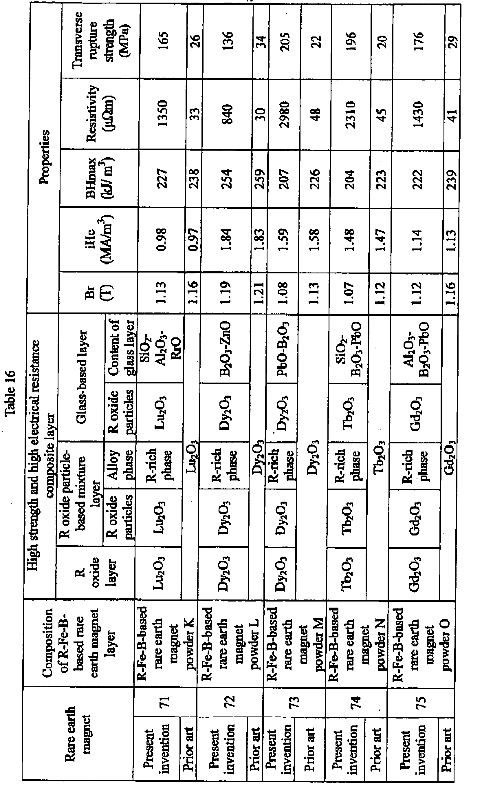

- From the results shown in Tables 14 through 17, it can be seen that the rare earth magnets 61 through 80 of the present invention have particularly higher strength and higher electrical resistance than the rare earth magnets 61 through 80 of the prior art.
- Example 5.
R-Fe-B-based rare earth magnet green compact layers having thickness of 3 mm were formed in a magnetic field from the R-Fe-B-based rare earth magnet powder A through T shown in Table 1.
Rare earth element oxide targets made from Dy2O3, Pr2O3, La2O3, Nd2O3, CeO2, Tb2O3, Gd2O3, Pr2O3, Y2O3, Er2O3, and Sm2O3 were prepared. Sputtered layers of oxide having thickness of 5 µm were formed on the surface of the R-Fe-B-based rare earth magnet green compact layer by using the rare earth oxide target, thereby making the stacked body comprising the R-Fe-B-based rare earth magnet green compact layer and the R oxide layer.
The glass powders having compositions shown in Tables 18 through 21 with the average particle size of 2 µm were prepared. A plurality of the stacked bodies were stacked so as to provided the glass powder layer between the R oxide layers of the stacked bodies facing each other, thereby making a plurality of stacked green compacts each constituted from the R-Fe-B-based rare earth magnet green compact layer, R oxide layer, glass powder layer, R oxide layer, and the R-Fe-B-based rare earth magnet green compact layer. The stacked green compact was hot-pressed at a temperature of 750°C under a pressure of 147 MPa, thereby making the rare earth magnets 81 through 100 of the present invention in the form of bulk measuring 10 mm in length, 10 mm in width, and 6.5 mm in height, comprising the high strength and high electrical resistance composite layer that was constituted from the R-Fe-B-based rare earth magnet layer having a composition shown in Tables 18 through 21, the R oxide layer having composition shown in Tables 18 through 21 and the glass layer having composition shown in Tables 18 through 21.
The rare earth magnets 81 through 100 of the present invention made as described above were polished on the top and bottom surfaces and four side faces thereof. A pair of voltage terminals were applied with a space of 4 mm from each other to the rare earth magnets 81 through 100 of the present invention that were polished, across one R-Fe-B-based rare earth magnet layer to the other R-Fe-B-based rare earth magnet layer of the side face that included the high strength and high electrical resistance composite layer while straddling the high strength and high electrical resistance composite layer. A pair of current terminals were applied with a space of 6 mm from each other so as to cross over the pair of voltage terminals. Resistance R = E/I (Ω) was calculated from the voltage drop E (V) across the voltage terminals when a predetermined current I (A) was flown between the current terminals, and resistance was calculated from the cross sectional area A (approximately 100 mm2) and the distance d between the terminals (= 4 mm) by formula R × A/d, with the results shown in Tables 18 through 21. Remanence, coercivity and maximum energy product of the rare earth magnets 81 through 100 of the present invention were measured, with the results shown in Tables 18 through 21, then transverse rupture strength of the rare earth magnets 81 through 100 of the present invention were measured, with the results shown in Tables 18 through 21. - Comparative Example 5
A plurality of stacked bodies comprising the R-Fe-B-based rare earth magnet green compact layer and the R oxide layers made in Example 5 were stacked so that the R oxide layers of the stacked bodies face each other, thereby making a plurality of stacked green compacts each constituted from the R-Fe-B-based rare earth magnet powder green compact layer and the R oxide layers. The stacked green compact was hot-pressed at a temperature of 750°C under a pressure of 147 MPa, thereby making the rare earth magnets 81 through 100 of the prior art in the form of bulk constituted from the R-Fe-B-based rare earth magnet layer having compositions shown in Tables 18 through 21 and the R oxide layer having compositions shown in Tables 18 through 21 stacked one on another, measuring 10 mm in length, 10 mm in width, and 6.5 mm in height.
The rare earth magnets 81 through 100 of the prior art made as described above were polished on the top and bottom surfaces and four side faces thereof. A pair of voltage terminals were applied with a space of 4 mm from each other to the rare earth magnets 81 through 100 of the present invention that were polished, across one R-Fe-B-based rare earth magnet layer to the other R-Fe-B-based rare earth magnet layer of the side face that included the R oxide layer while straddling the R oxide layer. A pair of current terminals were applied with a space of 6 mm from each other so as to cross over the pair of voltage terminals. Resistance R = E/I (Ω) was calculated from the voltage drop E (V) across the voltage terminals when a predetermined current I (A) was flown between the current terminals, and resistance was calculated from the cross sectional area A (approximately 100 mm2) and the distance d between the terminals (= 4 mm) by formula R × A/d, with the results shown in Tables 18 through 21.
Remanence, coercivity, and maximum energy product of the rare earth magnets 81 through 100 of the present invention were measured by the ordinary methods, with the results shown in Tables 18 through 21, then transverse rupture strength of the rare earth magnets 81 through 100 of the present invention were measured, with the results shown in Tables 18 through 21. Resistivity was measured by 4-probe method, with the results shown in Tables 18 through 21.
Remanence, coercivity and maximum energy product of the rare earth magnets 81 through 100 of the prior art were measured by the ordinary methods, with the results shown in Tables 18 through 21, then transverse rupture strength of the rare earth magnets 81 through 100 of the prior art were measured, with the results shown in Tables 18 through 21.Table 18 Rare earth magnet Composition of R-Fe-B-based rare earth magnet layer High strength and high electrical resistance composite layer Properties R oxide layer Glass layer Br (T) iHc (MA/m3) BHmax (kJ/ m3) Resistivity (µΩm) Transverse rupture strength (Mpa) Present invention 81 R-Fe-B-based rare earth magnet powder A Dy2O3 SiO2-BaO-Al2O3 1.19 1.54 251 345 120 Prior art - 1.19 1.52 251 38 24 Present invention 82 R-Fe-B-based rare earth magnet powder B Pr2O3 SiO2-BaO-B2O3 1.21 1.17 261 390 195 Prior art - 1.21 1.15 262 33 27 Present invention 83 R-Fe-B-based rare earth magnet powder C Ho2O3 SiO2-BaO-Li2O3 1.18 1.13 246 225 90 Prior art - 1.18 1.12 246 23 23 Present invention 84 R-Fe-B-based rare earth magnet powder D Dy2O3 SiO2-MgO-Al2O3 1.15 1.71 234 450 240 Prior art - 1.15 1.69 236 35 28 Present invention 85 R-Fe-B-based rare earth magnet powder E Nd2O3 SiO2-ZnO-RrO 1.17 1.63 244 420 120 Prior art - 1.17 1.61 245 50 24 Table 19 Rare earth magnet Composition of R-Fe-B-based rare earth magnet layer High strength and high electrical resistance composite layer Properties R oxide layer Glass layer Br (T) iHc (MA/m3) BHmax (kJ/m3) Resistivity (µΩm) Transverse rupture strength (MPa) Present invention 86 R-Fe-B-based rare earth magnet powder F Nd2O3 SiO2-B2O3-ZnO 1.19 1.16 251 360 120 Prior art - 1.19 1.15 251 40 24 Present invention 87 R-Fe-B-based rare earth magnet powder G Lu2O3 SiO2-Al2O3-RrO 1.17 0.98 245 330 180 Prior art - 1.18 0.97 246 25 26 Present invention 88 R-Fe-B-based rare earth magnet powder H Dy2O3 B2O3-ZnO 1.21 1.84 261 375 120 Prior art - 1.21 1.83 262 43 24 Present invention 89 R-Fe-B-based rare earth magnet powder I Dy2O3 PbO-B2O3 1.17 1.59 244 435 90 Prior art - 1.17 1.58 245 58 23 Present invention 90 R-Fe-B-based rare earth magnet powder J Tb2O3 SiO2-B2O3-PbO 1.16 1.48 240 405 120 Prior art - 1.16 1.47 241 48 24 Table 20 Rare earth magnet Composition of R-Fe-B-based rare earth magnet layer High strength and high electrical resistance composite layer Properties R oxide layer Glass layer Br (T) iHc (MA/m3) BHmax (kJ/m3) Resistivity (µΩm) Transverse rupture strength (MPa) Present invention 91 R-Fe-B-based rare earth magnet powder K Gd2O3 Al2O3-B2O3-PbO 1.20 1.14 256 315 105 Prior art - 1.20 1.13 257 35 24 Present invention 92 R-Fe-B-based rare earth magnet powder L Dy2O3 SnO-P2O5 1.19 1.54 251 300 150 Prior art - 1.19 1.52 252 25 25 Present invention 93 R-Fe-B-based rare earth magnet powder M Pr2O3 ZnO-P2O5 1.21 1.06 262 360 135 Prior art - 1.21 1.05 262 38 25 Present invention 94 R-Fe-B-based rare earth magnet powder N Y2O3 ZnO-P2O5 1.14 1.66 230 375 165 Prior art - 1.14 1.65 231 35 26 Present invention 95 R-Fe-B-based rare earth magnet powder O Er2O3 CuO-P2O5 1.16 1.51 240 345 165 Prior art - 1.16 1.50 241 30 26 Present invention 96 R-Fe-B-based rare earth magnet powder P Ho2O3 SiO2-B2O3-ZnO 1.19 1.40 251 360 135 Prior art - 1.19 1.39 251 38 25 Present invention 97 R-Fe-B-based rare earth magnet powder Q Dy2O3 SiO2-B2O3-RrO 1.19 1.81 250 593 134 Prior art - 1.19 1.79 251 21 23 Present invention 98 R-Fe-B-based rare earth magnet powder R Dy2O3 SiO2-B2O3-ZnO 1.22 1.50 266 667 149 Prior art - 1.23 1.49 268 24 24 Present invention 99 R-Fe-B-based rare earth magnet powder S Dy2O3 SiO2-B2O3-RrO 1.24 1.02 273 315 150 Prior art - 1.24 1.01 273 28 25 Present invention 100 R-Fe-B-based rare earth magnet powder T Dy2O3 SiO2-B2O3-Al2O3 1.16 1.50 240 450 180 Prior art - 1.16 1.48 241 45 26 - From the results shown in Tables 18 through 21, it can be seen that the rare earth magnets 81 through 100 of the present invention have particularly higher strength and higher electrical resistance than the rare earth magnets 81 through 100 of the prior art,
- Example 6
R oxide layer having thickness of 3 µm and compositions shown in Tables 22 through 25 were formed on the surfaces of the R-Fe-B-based rare earth magnet powders A through T having the average particle size of 300 µm that had been subjected to HDDR treatment shown in Table 1 by means of a powder coating sputtering apparatus, thereby to prepare oxide-coated R-Fe-B-based rare earth magnet powder.
The oxide-coated R-Fe-B-based rare earth magnet powder having the R oxide layer formed on the surface thereof was mixed with glass powders having compositions shown in Tables 22 through 25, all having the average particle size of 0.8 µm, and the mixed powder was formed preliminarily in a magnetic field under a pressure of 49 MPa and was then hot-pressed at a temperature of 730°C under a pressure of 294 MPa, thereby making the rare earth magnets 101 through 120 of the present invention in the form of bulk measuring 10 mm in length, 10 mm in width, and 7 mm in height of a structure such that the R-Fe-B-based rare earth magnet particles having compositions shown in Tables 22 through 25 were enclosed with the high strength and high electrical resistance composite layer comprising the R oxide layer and the glass layer.
The rare earth magnets 101 through 120 of the present invention in the form of bulk made as described above were polished on the surfaces thereof, and resistivity was measured with the results shown in Tables 22 through 25.
Remanence, coercivity, and maximum energy product of the rare earth magnets 101 through 120 of the present invention were measured by the ordinary methods, with the results shown in Tables 22 through 25, then transverse rupture strength of the rare earth magnets 101 through 120 of the present invention were measured, with the results shown in Tables 22 through 25. - Comparative Example 6
The oxide-coated R-Fe-B-based rare earth magnet powder made in Example 6 having theR oxide layer 3 µm in thickness formed on the surface thereof was subjected to preliminary forming in a magnetic field under a pressure of 49 MPa and was then subjected to hot pressing at a temperature of 730°C under a pressure of 294 MPa, thereby making the rare earth magnets 101 through 120 of the prior art in the form of bulk measuring 10 mm in length, 10 mm in width, and 7 mm in height having a structure such that the R-Fe-B-besed rare earth magnet particles were enclosed with the R oxide layers.
The rare earth magnets 101 through 120 of the prior art in the form of bulk made as described above were polished on the surfaces thereof, and resistivity was measured with the results shown in Tables 22 through 25,
Remanence, coercivity, and maximum energy product of the rare earth magnets 101 through 120 of the prior art were measured by the ordinary methods, with the results shown in Tables 22 through 25, then transverse rupture strength of the rare earth magnets 101 through 120 of the prior art were measured, with the results shown in Tables 22 through 25.Table 22 Rare earth magnet Composition of R-Fe-B-based rare earth magnet layer High strength and high electrical resistance composite layer Properties R oxide layer Glass layer Br (T) iHc (MA/m3) BHmax (kJ/m3) Resistivity (µΩm) Transverse rupture strength (MPa) Present invention 101 R-Fe-B-based rare earth magnet powder A Dy2O3 SiO2-BaO-Al2O3 1.11 1.54 218 1125 222 Prior art - 1.12 1.52 224 66 36 Present invention 102 R-Fe-B-based rare earth magnet powder B Pr2O3 SiO2-BaO-B2O3 1.14 1.17 231 390 137 Prior art - 1.15 1.15 235 63 27 Present invention 103 R-Fe-B-based rare earth magnet powder C Ho2O3 SiO2-BaO-Li2O3 1.10 1.13 215 1065 87 Prior art - 1.10 1.12 217 72 28 Present invention 104 R-Fe-B-based rare earth magnet powder D Dy2O3 SiO2-MgO-Al2O3 0.97 1.71 171 825 196 Prior art - 1.02 1.69 185 46 23 Present invention 105 R-Fe-B-based rare earth magnet powder E Nd2O3 SiO2-ZnO-RrO 1.10 1.63 214 735 146 Prior art - 1.11 1.61 220 43 25 Table 23 Rare earth magnet Composition of R-Fe-B-based rare earth magnet layer High strength and high electrical resistance composite layer Properties R oxide layer Glass layer Br (T) iHe (MA/m3) BHmax (kJ/m3) Resistivity (µΩm) Transverse rupture strength (MPa) Present invention 106 R-Fe-B-based rare earth magnet powder F Nd2O3 SiO2-B2O3-ZnO 1.14 1.16 231 375 179 Prior art - 1.15 1.15 236 36 35 Present invention 107 R-Fe-B-based rare earth magnet powder G Lu2O3 SiO2-Al2O3-RrO 1.15 0.98 234 660 220 Prior art - 1.16 0.97 238 33 26 Present invention 108 R-Fe-B-Dascd rare earth magnet powder H Dy2O3 B2O3-ZnO 1.20 1.84 257 585 182 Prior art - 1.21 1.83 259 30 34 Present invention 109 R-Fe-B-based rare earth magnet powder I Dy2O3 PbO-B2O3 1.11 1.59 221 840 187 Prior art - 1.13 1.58 226 48 22 Present invention 110 R-Fe-B-based rare earth magnet powder J Tb2O3 SiO2-B2O3-PbO 1.10 1.48 217 810 204 Prior art - 1.12 1.47 223 45 20 Table 24 Rare earth magnet Composition of R-Fe-B-based rare earth magnet layer High strength and high electrical resistance composite layer Properties R oxide layer Glass layer Br (T) iHc (MA/m3) BHmax (kJ/m3) Resistivity (µΩm) Transverse rupture strength (MPa) Present invention 111 R-Fe-B-based rare earth magnet powder K Gd2O3 Al2O3-B2O3-PbO 1.15 1.14 235 705 151 Prior art - 1.16 1.13 239 41 29 Present invention 112 R-Fe-B-based rare earth magnet powder L Dy2O3 SnO-P2O5 1.14 1.54 232 645 137 Prior art - 1.15 1.52 236 37 26 Present invention 113 R-Fe-B-based rare earth magnet powder M Pr2O3 ZnO-P2O5 1.16 1.06 238 750 214 Prior art - 1.17 1.05 245 40 33 Present invention 114 R-Fe-B-based rare earth magnet powder N Y2O3 ZnO-P2O5 1.08 1.66 207 825 233 Prior art - 1.10 1.65 214 44 26 Present invention 115 R-Fe-B-based rare earth magnet powder O Er2O3 CuO-P2O5 1.11 1.51 218 765 247 Prior art - 1.13 1.50 225 39 36 Table 25 Rare earth magnet Composition of R-Fe-B-based rare earth magnet layer High strength and high electrical resistance composite layer Properties R oxide layer Glass layer Br (T) iHc (MA/m3) BHmax (kJ/m3) Resistivity (µΩm) Transverse rupture strength (MPa) Present invention 116 R-Fe-B-based rare earth magnet powder P Ho2O3 SiO2-B2O3- ZnO 1.14 1.40 233 600 151 Prior art - 1.16 1.39 238 33 32 Present invention 117 R-Fe-B-based rare earth magnet powder Q Dy2O3 SiO2-B2O3-RrO 1.17 1.81 244 855 221 Prior art - 1.18 1.79 246 47 38 Present invention 118 R-Fe-B-based rare earth magnet powder R Dy2O3 SiO2-B2O3-ZnO 1.19 1.50 254 1005 249 Prior art - 1.20 1.49 257 56 21 Present invention 119 R-Fe-B-based rare earth magnet powder S Dy2O3 SiO2-B2O3-RrO 1.20 1.02 255 555 121 Prior art - 1.21 1.01 259 32 25 Present invention 120 R-Fe-B-based rare earth magnet powder T Dy2O3 SiO2-B2O3-Al2O3 1.10 1.50 215 885 210 Prior art - 1.11 1.48 221 50 29 - From the results shown in Tables 23 through 25, it can be seen that the rare earth magnets 101 through 120 of the present invention have particularly higher strength and higher electrical resistance than the rare earth magnets 101 through 120 of the prior art.
While preferred embodiments of the invention have been described and illustrated above, it should be understood that these are exemplary of the invention and are not to be considered as limiting. Additions, omissions, substitutions, and other modifications can be made without departing from the spirit or scope of the present invention, Accordingly, the invention is not to be considered as being limited by the foregoing description, and is only limited by the scope of the appended claims.
Claims (30)
- A rare earth magnet having high strength and high electrical resistance formed by stacking a composite layer which has high strength and high electrical resistance (hereinafter referred to as a high strength and high electrical resistance composite layer) and an R-Fe-B-based rare earth magnet layer (R represents one or more kind of rare earth element including Y),
wherein the high strength and high electrical resistance composite layer comprises a glass-based layer having a glass phase or a structure of R oxide particles dispersed in a glass phase, and R oxide particle-based mixture layers that are formed on both sides of the glass-based layer and which contain an R-rich alloy phase which contains 50 atomic % or more of R in a grain boundary of the R oxide particles. - The rare earth magnet having high strength and high electrical resistance according to claim 1, wherein the high strength and high electrical resistance composite layer further comprises an R oxide layer formed on the surface of the R oxide particle-based mixture layer opposite to a surface thereof that makes contact with the glass-based layer.
- The rare earth magnet having high strength and high electrical resistance according to claim 2, wherein R of the R oxide layer contained in the high strength and high electrical resistance composite layer is one or more selected from the group consisting of Y, Gd, Tb, Dy, Ho, Er, Tm, Yb, and Lu.
- The rare earth magnet having high strength and high electrical resistance according to claim 1, wherein the R-Fe-B-based rare earth magnet layer has a composition such as 5 to 20% of R and 3 to 20% of B (hereinafter % refers to atomic %), with the balance consisting af Fe and inevitable impurities.
- The rare earth magnet having high strength and high electrical resistance according to claim 1, wherein the R-Fe-B-based rare earth magnet layer has a composition such as 5 to 20% of R, 3 to 20% of B, and 0.001 to 5% of M (M represents one or more selected from the group consisting of Ga, Zr, Nb, Mo, Hf, Ta, W, Ni, Al, Ti, V, Cu, Cr, Ge, C, and Si), with the balance consisting of Fe and inevitable impurities.
- The rare earth magnet having high strength and high electrical resistance according to claim 1, wherein the R-Fe-B-based rare earth magnet layer has a composition such as 5 to 20% of R, 0.1 to 50% of Co, and 3 to 20% ofB, with the balance consisting of Fe and inevitable impurities.
- The rare earth magnet having high strength and high electrical resistance according to claim 1, wherein the R-Fe-B-based rare earth magnet layer has a composition such as 5 to 20% of R, 0.1 to 50% of Co, 3 to 20% of B, and 0.001 to 5% of M, with the balance consisting of Fe and inevitable impurities.
- The R-Fe-B-based rare earth magnet having high strength and high electrical resistance, wherein the R-Fe-B-based rare earth magnet layer according to claim 1,2,3,4, 5, 6 or 7 is a magnetically anisotropic HDDR magnetic layer having a recrystallization texture comprising adjoining recrystallized grains containing an R2Fe14B type intermetallic compound phase having a substantially tetragonal structure as a main phase, while the recrystallization texture has a fundamental structure having a constitution such that 50% by volume or more of the recrystallized grains have a shape such that a ratio b/a of the minimum grain size a and the maximum grain size b of the recrystallized grain is less than 2, and the average size of the recrystallized grains is in a range from 0.05 to 5 µm.
- A rare earth magnet having high strength and high electrical resistance having a structure such that R-Fe-B-based rare earth magnet particles are enclosed within a high strength and high electrical resistance composite layer,
wherein the high strength and high electrical resistance composite layer comprises a glass-based layer having a glass phase or a structure of R oxide particles dispersed in a glass phase, and R oxide particle-based mixture layers that are formed on both sides of the glass-based layer and which contain an R-rich alloy phase containing 50 atomic % or more of R in a grain boundary of the R oxide particles. - The rare earth magnet having high strength and high electrical resistance according to claim 9, wherein the high strength and high electrical resistance composite layer further comprises an R oxide layer formed on the surface of the R oxide particle-based mixture layer opposite to the surface thereof that makes contact with the glass-based layer.
- The rare earth magnet having high shength and high electrical resistance according to claim 10, wherein R of the R oxide layer contained in the high strength and high electrical resistance composite layer m is one or more selected from the group consisting of Y, Gd, Tb, Dy, Ho, Er, Tm, Yb, and Lu.
- The rare earth magnet having high strength and high electrical resistance according to claim 9, wherein the R-Fe-B-based rare earth magnet particles are particles of a rare earth magnet that have a composition such as 5 to 20% of R and 3 to 20% of B, with the balance consisting of Fe and inevitable impurities.
- The rare earth magnet having high strength and high electrical resistance according to claim 9, wherein the R-Fe-B-based rare earth magnet particles are particles of has a composition such as 5 to 20% of R, 3 to 20% of B, and 0.001 to 5% of M, with the balance consisting of Fe and inevitable impurities.
- The rare earth magnet having high strength and high electrical resistance according to claim 9, wherein the R-Fe-B-based rare earth magnet layer has a composition such as 5 to 20% of R, 0.1 to 50% of Co, and 3 to 20% ofB, with the balance consisting of Fe and inevitable impurities.
- The rare earth magnet having high strength and high electrical resistance according to claim 9, wherein the R-Fe-B-based rare earth magnet layer has a composition such as 5 to 20% of R, 0.1 to 50% of Co, 3 to 20% ofB, and 0.001 to 5% of M, with the balance consisting of Fe and inevitable impurities.
- The R-Fe-B-based rare earth magnet having high strength and high electrical resistance, wherein the R-Fe-B-based rare earth magnet layer according to claim 9, 10, 11, 12, 13, 14 or 15 is a magnetically anisotropic HDDR magnetic layer having a recrystallization texture comprising adjoining recrystallized grains containing an R2Fe14B type intermetallic compound phase of a substantially tetragonal structure as a main phase, while the recrystallization texture has a fundamental structure having a constitution such that 50% by volume or more of the recrystallized grains have a shape such that a ratio b/a of the minimum grain size a and the maximum grain size b of the recrystallized grains is less than 2, and the average size of the recrystallized grains is in a range from 0.05 to 5 µm.
- A rare earth magnet having high strength and high electrical resistance comprising: a composite layer having a high strength and high electrical resistance composite layer that is formed by stacking R oxide layers on both sides of a glass layer and an R-Fe-B-based rare earth magnet layer to be stacked, wherein the high strength and high electrical resistance composite layer is provided between the R-Fe-B-based rare earth magnet layers.
- The rare earth magnet having high strength and high electrical resistance according to claim 17, wherein R of the R oxide layer contained in the high strength and high electrical resistance composite layer m is one or more selected from the group consisting of Y, Gd, Tb, Dy, Ho, Er, Tm, Yb, and Lu.
- The rare earth magnet having high strength and high electrical resistance according to claim 17, wherein the R-Fe-B-based rare earth magnet layer has a composition such as 5 to 20% of R and 3 to 20% of B, with the balance consisting of Fe and inevitable impurities.
- The rare earth magnet having high strength and high electrical resistance according to claim 17, wherein the R-Fe-B-based rare earth magnet layer has a composition such as 5 to 20% of R, 3 to 20% ofB, and 0.001 to 5% of M, with the balance consisting of Fe and inevitable impurities.
- The rare earth magnet having high strength and high electrical resistance according to claim 17, wherein the R-Fe-B-based rare earth magnet layer has a composition such as 5 to 20% of R, 0.1 to 50% of Co, and 3 to 20% ofB, with the balance consisting of Fe and inevitable impurities.
- The rare earth magnet having high strength and high electrical resistance according to claim 17, wherein the R-Fe-B-based rare earth magnet layer has a composition such as 5 to 20% of R, 0.1 to 50% of Co, 3 to 20% of B, and 0.001 to 5% of M, with the balance consisting of Fe and inevitable impurities.
- The R-Fe-B-based rare earth magnet having high strength and high electrical resistance, wherein the R-Fe-B-based rare earth magnet layer according to claim 17, 18, 19, 20, 21 or 22 is a magnetically anisotropic HDDR magnetic layer having a recrystallization texture comprising adjoining recrystallized grains containing an R2Fe14B type intermetallic compound phase of a substantially tetragonal structure as a main phase, while the recrystallization texture has a fundamental structure having a constitution such that 50% by volume or more of the recrystallized grains have a shape such that a ratio b/a of the minimum grain size a and the maximum grain size b of the recrystallized grain is less than 2, and the average size of the recrystallized grains is in a range from 0.05 to 5 µm.
- A rare earth magnet having high strength and high electrical resistance having a structure such that R-Fe-B-based rare earth magnet particles are enclosed within a high strength and high electrical resistance composite layer formed by stacking R oxide layers on both sides of a glass layer in contact therewith.
- The rare earth magnet having high strength and high electrical resistance according to claim 24, wherein R of the R oxide layer contained in the high strength and high electrical resistance composite layer m is one or more selected from the group consisting of Y, Gd, Tb, Dy, Ho, Er, Tm, Yb, and Lu.
- The rare earth magnet having high strength and high electrical resistance according to claim 24, wherein the R-Fe-B-based rare earth magnet layer has a composition such as 5 to 20% of R and 3 to 20% of B, with the balance consisting of Fe and inevitable impurities.
- The rare earth magnet having high strength and high electrical resistance according to claim 24, wherein the R-Fe-B-based rare earth magnet layer has a composition such as 5 to 20% of R, 3 to 20% of B, and 0.001 to 5% of M, with the balance consisting of Fe and inevitable impurities.
- The rare earth magnet having high strength and high electrical resistance according to claim 24, wherein the R-Fe-B-based rare earth magnet layer has a composition such as 5 to 20% of R, 0.1 to 50% of Co, and 3 to 20% of B, with the balance consisting of Fe and inevitable impurities.
- The rare earth magnet having high strength and high electrical resistance according to claim 24, wherein the R-Fe-B-based rare earth magnet layer has a composition such as 5 to 20% of R, 0.1 to 50% of Co, 3 to 20% of B, and 0.001 to 5% of M, with the balance consisting of Fe and inevitable impurities.
- The R-Fe-B-based rare earth magnet having high strength and high electrical resistance, wherein the R-Fe-B-based rare earth magnet layer according to claim 24, 25, 26, 27, 28 or 29 is a magnetically anisotropic HDDR magnetic layer having a recrystallization texture comprising adjoining recrystallized grains containing an R2Fe14B type intermetallic compound phase of a substantially tetragonal structure as a main phase, while the recrystallization texture has a fundamental structure having a constitution such that 50% by volume or more of the recrystallized grains have a shape such that a ratio b/a of the minimum grain size a and the maximum grain size b of the recrystallized grains is less than 2, and the average size of the recrystallized grains is in a range from 0.05 to 5 µm.
Applications Claiming Priority (3)
| Application Number | Priority Date | Filing Date | Title |
|---|---|---|---|
| JP2005170477A JP2006344856A (en) | 2005-06-10 | 2005-06-10 | Rare earth magnet with high strength and high resistance |
| JP2005170476A JP2006344855A (en) | 2005-06-10 | 2005-06-10 | Rare earth magnet with high strength and high resistance |
| JP2005170475A JP2006344854A (en) | 2005-06-10 | 2005-06-10 | Rare earth magnet with high strength and high resistance |
Publications (3)
| Publication Number | Publication Date |
|---|---|
| EP1744328A2 true EP1744328A2 (en) | 2007-01-17 |
| EP1744328A3 EP1744328A3 (en) | 2010-06-30 |
| EP1744328B1 EP1744328B1 (en) | 2012-07-25 |
Family
ID=37459416
Family Applications (1)
| Application Number | Title | Priority Date | Filing Date |
|---|---|---|---|
| EP06011967A Not-in-force EP1744328B1 (en) | 2005-06-10 | 2006-06-09 | Rare earth magnet having high strength and high electrical resistance |
Country Status (2)
| Country | Link |
|---|---|
| US (2) | US7919200B2 (en) |
| EP (1) | EP1744328B1 (en) |
Cited By (7)
| Publication number | Priority date | Publication date | Assignee | Title |
|---|---|---|---|---|
| EP2444985A1 (en) * | 2010-10-25 | 2012-04-25 | Toyota Jidosha Kabushiki Kaisha | Production method of rare earth magnet |
| DE102012210310A1 (en) * | 2012-06-19 | 2013-12-19 | Siemens Aktiengesellschaft | Preparing permanent magnet, comprises preparing first slurry comprising magnetic particles with first dimension and organic component, applying first film made of first slurry on carrier film, and passing carrier film on blade |
| CN103843082A (en) * | 2011-09-30 | 2014-06-04 | 日东电工株式会社 | Permanent magnet and permanent magnet manufacturing method |
| EP2977997A4 (en) * | 2013-03-18 | 2016-03-16 | Intermetallics Co Ltd | RFeB-BASED SINTERED MAGNET PRODUCTION METHOD AND RFeB-BASED SINTERED MAGNETS |
| US20160273091A1 (en) | 2013-03-18 | 2016-09-22 | Intermetallics Co., Ltd. | RFeB SYSTEM SINTERED MAGNET PRODUCTION METHOD AND RFeB SYSTEM SINTERED MAGNET |
| CN107533893A (en) * | 2015-04-30 | 2018-01-02 | 株式会社Ihi | The manufacture method of rare earth element permanent magnet and rare earth element permanent magnet |
| US10312019B2 (en) | 2012-11-14 | 2019-06-04 | Volkswagen Aktiengesellschaft | Method for producing a permanent magnet and permanent magnet |
Families Citing this family (22)
| Publication number | Priority date | Publication date | Assignee | Title |
|---|---|---|---|---|
| US7559996B2 (en) * | 2005-07-22 | 2009-07-14 | Shin-Etsu Chemical Co., Ltd. | Rare earth permanent magnet, making method, and permanent magnet rotary machine |
| US20100243946A1 (en) * | 2009-03-31 | 2010-09-30 | General Electric Company | Methods of making high resistivity magnetic materials |
| US8979973B2 (en) * | 2009-07-31 | 2015-03-17 | Hitachi Metals, Ltd. | Method and device for recovering hydrogen pulverized powder of raw-material alloy for rare-earth magnet |
| US20110200839A1 (en) * | 2010-02-17 | 2011-08-18 | Melania Marinescu | Rare Earth Laminated, Composite Magnets With Increased Electrical Resistivity |
| US10395822B2 (en) * | 2010-03-23 | 2019-08-27 | Tdk Corporation | Rare-earth magnet, method of manufacturing rare-earth magnet, and rotator |
| EP2555208B1 (en) * | 2010-03-30 | 2021-05-05 | TDK Corporation | Method for producing sintered magnet |
| EP2503571B1 (en) * | 2010-03-31 | 2015-05-06 | Nitto Denko Corporation | Manufacturing method for permanent magnet |
| US20130038160A1 (en) * | 2011-08-09 | 2013-02-14 | Jinfang Liu | Sequentially laminated, rare earth, permanent magnets with sulfide-based dielectric layers and reinforced by diffusion reaction layers |
| US9064625B2 (en) | 2011-08-09 | 2015-06-23 | Electron Energy Corporation | Methods for sequentially laminating rare earth permanent magnets with suflide-based dielectric layer |
| US20130038164A1 (en) * | 2011-08-09 | 2013-02-14 | Jinfang Liu | Sequentially laminated, rare earth, permanent magnets with dielectric layers reinforced by transition and/or diffusion reaction layers |
| CN103021610B (en) * | 2011-09-26 | 2015-12-02 | 东莞市炫耀电子有限公司 | Novel composite permanent magnetic material and preparation method thereof |
| JP5908247B2 (en) * | 2011-09-30 | 2016-04-26 | 日東電工株式会社 | Method for manufacturing permanent magnet |
| JP6037128B2 (en) | 2013-03-13 | 2016-11-30 | 戸田工業株式会社 | R-T-B rare earth magnet powder, method for producing R-T-B rare earth magnet powder, and bonded magnet |
| DE102013213494A1 (en) | 2013-07-10 | 2015-01-29 | Volkswagen Aktiengesellschaft | Method for producing a permanent magnet and permanent magnet and electric machine with such a permanent magnet |
| US9786419B2 (en) | 2013-10-09 | 2017-10-10 | Ford Global Technologies, Llc | Grain boundary diffusion process for rare-earth magnets |
| CN103774109B (en) * | 2014-01-26 | 2016-06-08 | 浙江大学 | A kind of supersensitive Fe-Y-B metallic film and preparation method thereof |
| JP2017157625A (en) * | 2016-02-29 | 2017-09-07 | Tdk株式会社 | Rare earth sintered magnet |
| JP6759649B2 (en) * | 2016-03-23 | 2020-09-23 | Tdk株式会社 | Rare earth magnets and motors |
| TWI688131B (en) * | 2016-09-14 | 2020-03-11 | 日商東芝記憶體股份有限公司 | Semiconductor device |
| US11024449B2 (en) * | 2017-06-06 | 2021-06-01 | Apple Inc. | Multipole elastomeric magnet with magnetic-field shunt |
| CN111048384B (en) * | 2019-12-19 | 2022-07-08 | 西安医学院 | A scanning electron microscope test platform |
| DE102020211857A1 (en) * | 2020-09-22 | 2022-03-24 | Mimplus Technologies Gmbh & Co. Kg | Process for producing a permanent magnet from a magnetic starting material |
Citations (1)
| Publication number | Priority date | Publication date | Assignee | Title |
|---|---|---|---|---|
| JP2002064010A (en) | 2000-08-22 | 2002-02-28 | Shin Etsu Chem Co Ltd | High specific resistance rare earth magnet and method of manufacturing the same |
Family Cites Families (16)
| Publication number | Priority date | Publication date | Assignee | Title |
|---|---|---|---|---|
| JP2576672B2 (en) | 1989-07-31 | 1997-01-29 | 三菱マテリアル株式会社 | Rare earth-Fe-Co-B permanent magnet powder and bonded magnet with excellent magnetic anisotropy and corrosion resistance |
| DE69009335T2 (en) * | 1989-07-31 | 1994-11-03 | Mitsubishi Materials Corp | Rare earth powder for permanent magnet, manufacturing process and bonded magnet. |
| JP2576672Y2 (en) | 1993-06-10 | 1998-07-16 | サンデン株式会社 | Tube pump |
| JPH097868A (en) | 1995-06-22 | 1997-01-10 | Shin Etsu Chem Co Ltd | Highly corrosion-resistant permanent magnet and manufacturing method thereof |
| WO1999000802A1 (en) * | 1997-06-26 | 1999-01-07 | Sumitomo Special Metals Co., Ltd. | Method of producing laminated permanent magnet |
| JP3129703B2 (en) | 1998-09-07 | 2001-01-31 | 日本電気株式会社 | Semiconductor device having MOS transistor and method of manufacturing the same |
| JP2001068317A (en) | 1999-08-31 | 2001-03-16 | Shin Etsu Chem Co Ltd | Nd-Fe-B sintered magnet and method for manufacturing the same |
| US6136100A (en) * | 1999-09-29 | 2000-10-24 | Magnequench International, Inc. | Rare-earth alloy powders for magnets and process for making magnets from rare-earth alloy powders |
| JP4337209B2 (en) * | 2000-02-22 | 2009-09-30 | 日立金属株式会社 | Permanent magnet thin film and manufacturing method thereof |
| WO2002013209A2 (en) * | 2000-08-03 | 2002-02-14 | Sanei Kasei Co., Limited | Nanocomposite permanent magnet |
| DE60139594D1 (en) * | 2000-11-28 | 2009-10-01 | Nec Tokin Corp | Magnetic core with bonded magnet, comprising magnetic powder of which the surface of the particles is coated with oxidation-resistant metal |
| JP2004031780A (en) | 2002-06-27 | 2004-01-29 | Nissan Motor Co Ltd | Rare earth magnet, method of manufacturing the same, and motor using rare earth magnet |
| JP2004031781A (en) | 2002-06-27 | 2004-01-29 | Nissan Motor Co Ltd | Rare earth magnet, method of manufacturing the same, and motor using rare earth magnet |
| JP2005093350A (en) | 2003-09-19 | 2005-04-07 | Toyota Central Res & Dev Lab Inc | Insulating film, magnetic core powder and powder magnetic core, and methods for producing them |
| JP4238114B2 (en) | 2003-11-07 | 2009-03-11 | 株式会社日立製作所 | Powder for high resistance rare earth magnet and method for producing the same, rare earth magnet and method for producing the same, rotor for motor and motor |
| JP4654709B2 (en) * | 2004-07-28 | 2011-03-23 | 株式会社日立製作所 | Rare earth magnets |
-
2006
- 2006-06-09 EP EP06011967A patent/EP1744328B1/en not_active Not-in-force
- 2006-06-09 US US11/449,874 patent/US7919200B2/en not_active Expired - Fee Related
-
2011
- 2011-01-28 US US12/929,487 patent/US8481179B2/en not_active Expired - Fee Related
Patent Citations (1)
| Publication number | Priority date | Publication date | Assignee | Title |
|---|---|---|---|---|
| JP2002064010A (en) | 2000-08-22 | 2002-02-28 | Shin Etsu Chem Co Ltd | High specific resistance rare earth magnet and method of manufacturing the same |
Cited By (10)
| Publication number | Priority date | Publication date | Assignee | Title |
|---|---|---|---|---|
| EP2444985A1 (en) * | 2010-10-25 | 2012-04-25 | Toyota Jidosha Kabushiki Kaisha | Production method of rare earth magnet |
| WO2012056755A1 (en) * | 2010-10-25 | 2012-05-03 | Toyota Jidosha Kabushiki Kaisha | Production method of rare earth magnet |
| US9520230B2 (en) | 2010-10-25 | 2016-12-13 | Toyota Jidosha Kabushiki Kaisha | Production method of rare earth magnet |
| CN103843082A (en) * | 2011-09-30 | 2014-06-04 | 日东电工株式会社 | Permanent magnet and permanent magnet manufacturing method |
| DE102012210310A1 (en) * | 2012-06-19 | 2013-12-19 | Siemens Aktiengesellschaft | Preparing permanent magnet, comprises preparing first slurry comprising magnetic particles with first dimension and organic component, applying first film made of first slurry on carrier film, and passing carrier film on blade |
| US10312019B2 (en) | 2012-11-14 | 2019-06-04 | Volkswagen Aktiengesellschaft | Method for producing a permanent magnet and permanent magnet |
| EP2977997A4 (en) * | 2013-03-18 | 2016-03-16 | Intermetallics Co Ltd | RFeB-BASED SINTERED MAGNET PRODUCTION METHOD AND RFeB-BASED SINTERED MAGNETS |
| US20160273091A1 (en) | 2013-03-18 | 2016-09-22 | Intermetallics Co., Ltd. | RFeB SYSTEM SINTERED MAGNET PRODUCTION METHOD AND RFeB SYSTEM SINTERED MAGNET |
| CN107533893A (en) * | 2015-04-30 | 2018-01-02 | 株式会社Ihi | The manufacture method of rare earth element permanent magnet and rare earth element permanent magnet |
| EP3291251A4 (en) * | 2015-04-30 | 2018-12-12 | IHI Corporation | Rare earth permanent magnet and method for producing rare earth permanent magnet |
Also Published As
| Publication number | Publication date |
|---|---|
| EP1744328B1 (en) | 2012-07-25 |
| US20110128106A1 (en) | 2011-06-02 |
| US20060292395A1 (en) | 2006-12-28 |
| US7919200B2 (en) | 2011-04-05 |
| EP1744328A3 (en) | 2010-06-30 |
| US8481179B2 (en) | 2013-07-09 |
Similar Documents
| Publication | Publication Date | Title |
|---|---|---|
| US8481179B2 (en) | Rare earth magnet having high strength and high electrical resistance | |
| CN101030467B (en) | Functionally graded rare earth permanent magnets | |
| US10312019B2 (en) | Method for producing a permanent magnet and permanent magnet | |
| CN102639266B (en) | Powder for magnet | |
| EP1383143B1 (en) | Method of producing a solid material for magnet | |
| US20150155082A1 (en) | Rare Earth Laminated, Composite Magnets With Increased Electrical Rersistivity | |
| EP4287226A1 (en) | Nd-fe-b multilayer sintered magnet and method for producing same | |
| EP1947657A1 (en) | Rear earth alloy binderless magnet and method for manufacture thereof | |
| WO2013022940A1 (en) | Methods for sequentially laminating rare earth permanent magnets with sulfide-based dielectric layers | |
| WO2003085684A1 (en) | Composite rare earth anisotropic bonded magnet, compound for composite rare earth anisotropic bonded magnet, and method for production thereof | |
| JP4677942B2 (en) | Method for producing R-Fe-B rare earth sintered magnet | |
| JP4618553B2 (en) | Method for producing RTB-based sintered magnet | |
| EP0921533B1 (en) | Method of producing laminated permanent magnet | |
| EP3511959B1 (en) | Soft magnetic alloy and magnetic device | |
| WO2013022942A1 (en) | Sequentially laminated, rare earth, permanent magnets with dielectric layers reinforced by transition and/or diffusion reaction layers | |
| JP3731597B2 (en) | Composite rare earth anisotropic bonded magnet, compound for composite rare earth anisotropic bonded magnet, and manufacturing method thereof | |
| JP2006344856A (en) | Rare earth magnet with high strength and high resistance | |
| JP2006344854A (en) | Rare earth magnet with high strength and high resistance | |
| JP2006344855A (en) | Rare earth magnet with high strength and high resistance | |
| KR102922457B1 (en) | Bonded magnet to which grain boundary diffusion is applied, method of manufacturing the same, and apparatus including bonded magnet to which grain boundary diffusion is applied | |
| JPH11329809A (en) | Permanent magnet having inclination characteristic of electric resistance rate and manufacture thereof. | |
| JP4466491B2 (en) | Power motor | |
| JP2025177285A (en) | Laminated magnet and motor | |
| JP2024016680A (en) | neodymium laminated sintered magnet | |
| JP2025177294A (en) | Laminated magnet and motor |
Legal Events
| Date | Code | Title | Description |
|---|---|---|---|
| PUAI | Public reference made under article 153(3) epc to a published international application that has entered the european phase |
Free format text: ORIGINAL CODE: 0009012 |
|
| AK | Designated contracting states |
Kind code of ref document: A2 Designated state(s): AT BE BG CH CY CZ DE DK EE ES FI FR GB GR HU IE IS IT LI LT LU LV MC NL PL PT RO SE SI SK TR |
|
| AX | Request for extension of the european patent |
Extension state: AL BA HR MK YU |
|
| RAP1 | Party data changed (applicant data changed or rights of an application transferred) |
Owner name: NISSAN MOTOR CO., LTD. Owner name: MITSUBISHI MATERIALS PMG CORPORATION |
|
| RAP1 | Party data changed (applicant data changed or rights of an application transferred) |
Owner name: NISSAN MOTOR CO., LTD. |
|
| RIC1 | Information provided on ipc code assigned before grant |
Ipc: H01F 41/02 20060101ALI20100318BHEP Ipc: H01F 10/12 20060101ALI20100318BHEP Ipc: H01F 1/057 20060101AFI20061213BHEP |
|
| PUAL | Search report despatched |
Free format text: ORIGINAL CODE: 0009013 |
|
| AK | Designated contracting states |
Kind code of ref document: A3 Designated state(s): AT BE BG CH CY CZ DE DK EE ES FI FR GB GR HU IE IS IT LI LT LU LV MC NL PL PT RO SE SI SK TR |
|
| AX | Request for extension of the european patent |
Extension state: AL BA HR MK RS |
|
| 17P | Request for examination filed |
Effective date: 20101216 |
|
| AKX | Designation fees paid |
Designated state(s): DE FR GB |
|
| 17Q | First examination report despatched |
Effective date: 20111014 |
|
| GRAP | Despatch of communication of intention to grant a patent |
Free format text: ORIGINAL CODE: EPIDOSNIGR1 |
|
| RIN1 | Information on inventor provided before grant (corrected) |
Inventor name: MORIMOTO, KOICHIRO Inventor name: KAWASHITA, YOSHIO Inventor name: TAYU, TETSUROU Inventor name: WATANABE, MUNEAKI Inventor name: MORI, KATSUHIKO Inventor name: KANO, MAKOTO Inventor name: NAKAYAMA, RYOJI |
|
| GRAS | Grant fee paid |
Free format text: ORIGINAL CODE: EPIDOSNIGR3 |
|
| GRAA | (expected) grant |
Free format text: ORIGINAL CODE: 0009210 |
|
| AK | Designated contracting states |
Kind code of ref document: B1 Designated state(s): DE FR GB |
|
| REG | Reference to a national code |
Ref country code: GB Ref legal event code: FG4D |
|
| REG | Reference to a national code |
Ref country code: DE Ref legal event code: R096 Ref document number: 602006030916 Country of ref document: DE Effective date: 20120920 |
|
| PLBE | No opposition filed within time limit |
Free format text: ORIGINAL CODE: 0009261 |
|
| STAA | Information on the status of an ep patent application or granted ep patent |
Free format text: STATUS: NO OPPOSITION FILED WITHIN TIME LIMIT |
|
| 26N | No opposition filed |
Effective date: 20130426 |
|
| REG | Reference to a national code |
Ref country code: DE Ref legal event code: R097 Ref document number: 602006030916 Country of ref document: DE Effective date: 20130426 |
|
| REG | Reference to a national code |
Ref country code: FR Ref legal event code: PLFP Year of fee payment: 10 |
|
| PGFP | Annual fee paid to national office [announced via postgrant information from national office to epo] |
Ref country code: GB Payment date: 20150624 Year of fee payment: 10 Ref country code: DE Payment date: 20150609 Year of fee payment: 10 |
|
| PGFP | Annual fee paid to national office [announced via postgrant information from national office to epo] |
Ref country code: FR Payment date: 20150618 Year of fee payment: 10 |
|
| REG | Reference to a national code |
Ref country code: DE Ref legal event code: R119 Ref document number: 602006030916 Country of ref document: DE |
|
| GBPC | Gb: european patent ceased through non-payment of renewal fee |
Effective date: 20160609 |
|
| REG | Reference to a national code |
Ref country code: FR Ref legal event code: ST Effective date: 20170228 |
|
| PG25 | Lapsed in a contracting state [announced via postgrant information from national office to epo] |
Ref country code: DE Free format text: LAPSE BECAUSE OF NON-PAYMENT OF DUE FEES Effective date: 20170103 Ref country code: FR Free format text: LAPSE BECAUSE OF NON-PAYMENT OF DUE FEES Effective date: 20160630 |
|
| PG25 | Lapsed in a contracting state [announced via postgrant information from national office to epo] |
Ref country code: GB Free format text: LAPSE BECAUSE OF NON-PAYMENT OF DUE FEES Effective date: 20160609 |