EP1743823A1 - Entraînement pour véhicule de travail - Google Patents
Entraînement pour véhicule de travail Download PDFInfo
- Publication number
- EP1743823A1 EP1743823A1 EP06123361A EP06123361A EP1743823A1 EP 1743823 A1 EP1743823 A1 EP 1743823A1 EP 06123361 A EP06123361 A EP 06123361A EP 06123361 A EP06123361 A EP 06123361A EP 1743823 A1 EP1743823 A1 EP 1743823A1
- Authority
- EP
- European Patent Office
- Prior art keywords
- actuator
- hydraulic motor
- displacement volume
- hydraulic
- speed
- Prior art date
- Legal status (The legal status is an assumption and is not a legal conclusion. Google has not performed a legal analysis and makes no representation as to the accuracy of the status listed.)
- Granted
Links
- 238000006073 displacement reaction Methods 0.000 claims abstract description 31
- 238000003306 harvesting Methods 0.000 claims description 4
- 230000007935 neutral effect Effects 0.000 claims description 4
- 229920000742 Cotton Polymers 0.000 claims description 2
- 239000004459 forage Substances 0.000 claims description 2
- 230000000694 effects Effects 0.000 description 9
- 230000002093 peripheral effect Effects 0.000 description 6
- 230000005540 biological transmission Effects 0.000 description 4
- 238000002485 combustion reaction Methods 0.000 description 4
- 238000000034 method Methods 0.000 description 4
- 239000012530 fluid Substances 0.000 description 3
- 238000009987 spinning Methods 0.000 description 3
- 241001124569 Lycaenidae Species 0.000 description 1
- 240000000111 Saccharum officinarum Species 0.000 description 1
- 235000007201 Saccharum officinarum Nutrition 0.000 description 1
- 230000003213 activating effect Effects 0.000 description 1
- 230000004913 activation Effects 0.000 description 1
- 238000011217 control strategy Methods 0.000 description 1
- 238000010586 diagram Methods 0.000 description 1
- 239000000446 fuel Substances 0.000 description 1
- 238000012544 monitoring process Methods 0.000 description 1
- 238000005096 rolling process Methods 0.000 description 1
Images

Classifications
-
- B—PERFORMING OPERATIONS; TRANSPORTING
- B60—VEHICLES IN GENERAL
- B60K—ARRANGEMENT OR MOUNTING OF PROPULSION UNITS OR OF TRANSMISSIONS IN VEHICLES; ARRANGEMENT OR MOUNTING OF PLURAL DIVERSE PRIME-MOVERS IN VEHICLES; AUXILIARY DRIVES FOR VEHICLES; INSTRUMENTATION OR DASHBOARDS FOR VEHICLES; ARRANGEMENTS IN CONNECTION WITH COOLING, AIR INTAKE, GAS EXHAUST OR FUEL SUPPLY OF PROPULSION UNITS IN VEHICLES
- B60K17/00—Arrangement or mounting of transmissions in vehicles
- B60K17/04—Arrangement or mounting of transmissions in vehicles characterised by arrangement, location, or kind of gearing
- B60K17/10—Arrangement or mounting of transmissions in vehicles characterised by arrangement, location, or kind of gearing of fluid gearing
-
- B—PERFORMING OPERATIONS; TRANSPORTING
- B60—VEHICLES IN GENERAL
- B60W—CONJOINT CONTROL OF VEHICLE SUB-UNITS OF DIFFERENT TYPE OR DIFFERENT FUNCTION; CONTROL SYSTEMS SPECIALLY ADAPTED FOR HYBRID VEHICLES; ROAD VEHICLE DRIVE CONTROL SYSTEMS FOR PURPOSES NOT RELATED TO THE CONTROL OF A PARTICULAR SUB-UNIT
- B60W10/00—Conjoint control of vehicle sub-units of different type or different function
- B60W10/10—Conjoint control of vehicle sub-units of different type or different function including control of change-speed gearings
- B60W10/101—Infinitely variable gearings
- B60W10/103—Infinitely variable gearings of fluid type
-
- B—PERFORMING OPERATIONS; TRANSPORTING
- B60—VEHICLES IN GENERAL
- B60W—CONJOINT CONTROL OF VEHICLE SUB-UNITS OF DIFFERENT TYPE OR DIFFERENT FUNCTION; CONTROL SYSTEMS SPECIALLY ADAPTED FOR HYBRID VEHICLES; ROAD VEHICLE DRIVE CONTROL SYSTEMS FOR PURPOSES NOT RELATED TO THE CONTROL OF A PARTICULAR SUB-UNIT
- B60W10/00—Conjoint control of vehicle sub-units of different type or different function
- B60W10/18—Conjoint control of vehicle sub-units of different type or different function including control of braking systems
- B60W10/184—Conjoint control of vehicle sub-units of different type or different function including control of braking systems with wheel brakes
-
- B—PERFORMING OPERATIONS; TRANSPORTING
- B60—VEHICLES IN GENERAL
- B60W—CONJOINT CONTROL OF VEHICLE SUB-UNITS OF DIFFERENT TYPE OR DIFFERENT FUNCTION; CONTROL SYSTEMS SPECIALLY ADAPTED FOR HYBRID VEHICLES; ROAD VEHICLE DRIVE CONTROL SYSTEMS FOR PURPOSES NOT RELATED TO THE CONTROL OF A PARTICULAR SUB-UNIT
- B60W30/00—Purposes of road vehicle drive control systems not related to the control of a particular sub-unit, e.g. of systems using conjoint control of vehicle sub-units, or advanced driver assistance systems for ensuring comfort, stability and safety or drive control systems for propelling or retarding the vehicle
- B60W30/18—Propelling the vehicle
- B60W30/18009—Propelling the vehicle related to particular drive situations
- B60W30/18109—Braking
-
- F—MECHANICAL ENGINEERING; LIGHTING; HEATING; WEAPONS; BLASTING
- F16—ENGINEERING ELEMENTS AND UNITS; GENERAL MEASURES FOR PRODUCING AND MAINTAINING EFFECTIVE FUNCTIONING OF MACHINES OR INSTALLATIONS; THERMAL INSULATION IN GENERAL
- F16H—GEARING
- F16H61/00—Control functions within control units of change-speed- or reversing-gearings for conveying rotary motion ; Control of exclusively fluid gearing, friction gearing, gearings with endless flexible members or other particular types of gearing
- F16H61/38—Control of exclusively fluid gearing
- F16H61/40—Control of exclusively fluid gearing hydrostatic
- F16H61/4157—Control of braking, e.g. preventing pump over-speeding when motor acts as a pump
-
- F—MECHANICAL ENGINEERING; LIGHTING; HEATING; WEAPONS; BLASTING
- F16—ENGINEERING ELEMENTS AND UNITS; GENERAL MEASURES FOR PRODUCING AND MAINTAINING EFFECTIVE FUNCTIONING OF MACHINES OR INSTALLATIONS; THERMAL INSULATION IN GENERAL
- F16H—GEARING
- F16H61/00—Control functions within control units of change-speed- or reversing-gearings for conveying rotary motion ; Control of exclusively fluid gearing, friction gearing, gearings with endless flexible members or other particular types of gearing
- F16H61/38—Control of exclusively fluid gearing
- F16H61/40—Control of exclusively fluid gearing hydrostatic
- F16H61/42—Control of exclusively fluid gearing hydrostatic involving adjustment of a pump or motor with adjustable output or capacity
- F16H61/421—Motor capacity control by electro-hydraulic control means, e.g. using solenoid valves
-
- B—PERFORMING OPERATIONS; TRANSPORTING
- B60—VEHICLES IN GENERAL
- B60T—VEHICLE BRAKE CONTROL SYSTEMS OR PARTS THEREOF; BRAKE CONTROL SYSTEMS OR PARTS THEREOF, IN GENERAL; ARRANGEMENT OF BRAKING ELEMENTS ON VEHICLES IN GENERAL; PORTABLE DEVICES FOR PREVENTING UNWANTED MOVEMENT OF VEHICLES; VEHICLE MODIFICATIONS TO FACILITATE COOLING OF BRAKES
- B60T2201/00—Particular use of vehicle brake systems; Special systems using also the brakes; Special software modules within the brake system controller
- B60T2201/04—Hill descent control
-
- B—PERFORMING OPERATIONS; TRANSPORTING
- B60—VEHICLES IN GENERAL
- B60W—CONJOINT CONTROL OF VEHICLE SUB-UNITS OF DIFFERENT TYPE OR DIFFERENT FUNCTION; CONTROL SYSTEMS SPECIALLY ADAPTED FOR HYBRID VEHICLES; ROAD VEHICLE DRIVE CONTROL SYSTEMS FOR PURPOSES NOT RELATED TO THE CONTROL OF A PARTICULAR SUB-UNIT
- B60W2520/00—Input parameters relating to overall vehicle dynamics
- B60W2520/26—Wheel slip
-
- B—PERFORMING OPERATIONS; TRANSPORTING
- B60—VEHICLES IN GENERAL
- B60W—CONJOINT CONTROL OF VEHICLE SUB-UNITS OF DIFFERENT TYPE OR DIFFERENT FUNCTION; CONTROL SYSTEMS SPECIALLY ADAPTED FOR HYBRID VEHICLES; ROAD VEHICLE DRIVE CONTROL SYSTEMS FOR PURPOSES NOT RELATED TO THE CONTROL OF A PARTICULAR SUB-UNIT
- B60W2520/00—Input parameters relating to overall vehicle dynamics
- B60W2520/28—Wheel speed
-
- B—PERFORMING OPERATIONS; TRANSPORTING
- B60—VEHICLES IN GENERAL
- B60W—CONJOINT CONTROL OF VEHICLE SUB-UNITS OF DIFFERENT TYPE OR DIFFERENT FUNCTION; CONTROL SYSTEMS SPECIALLY ADAPTED FOR HYBRID VEHICLES; ROAD VEHICLE DRIVE CONTROL SYSTEMS FOR PURPOSES NOT RELATED TO THE CONTROL OF A PARTICULAR SUB-UNIT
- B60W2540/00—Input parameters relating to occupants
- B60W2540/10—Accelerator pedal position
- B60W2540/106—Rate of change
-
- F—MECHANICAL ENGINEERING; LIGHTING; HEATING; WEAPONS; BLASTING
- F16—ENGINEERING ELEMENTS AND UNITS; GENERAL MEASURES FOR PRODUCING AND MAINTAINING EFFECTIVE FUNCTIONING OF MACHINES OR INSTALLATIONS; THERMAL INSULATION IN GENERAL
- F16H—GEARING
- F16H59/00—Control inputs to control units of change-speed-, or reversing-gearings for conveying rotary motion
- F16H59/50—Inputs being a function of the status of the machine, e.g. position of doors or safety belts
- F16H2059/506—Wheel slip
-
- F—MECHANICAL ENGINEERING; LIGHTING; HEATING; WEAPONS; BLASTING
- F16—ENGINEERING ELEMENTS AND UNITS; GENERAL MEASURES FOR PRODUCING AND MAINTAINING EFFECTIVE FUNCTIONING OF MACHINES OR INSTALLATIONS; THERMAL INSULATION IN GENERAL
- F16H—GEARING
- F16H59/00—Control inputs to control units of change-speed-, or reversing-gearings for conveying rotary motion
- F16H59/36—Inputs being a function of speed
- F16H59/44—Inputs being a function of speed dependent on machine speed of the machine, e.g. the vehicle
-
- F—MECHANICAL ENGINEERING; LIGHTING; HEATING; WEAPONS; BLASTING
- F16—ENGINEERING ELEMENTS AND UNITS; GENERAL MEASURES FOR PRODUCING AND MAINTAINING EFFECTIVE FUNCTIONING OF MACHINES OR INSTALLATIONS; THERMAL INSULATION IN GENERAL
- F16H—GEARING
- F16H63/00—Control outputs from the control unit to change-speed- or reversing-gearings for conveying rotary motion or to other devices than the final output mechanism
- F16H63/40—Control outputs from the control unit to change-speed- or reversing-gearings for conveying rotary motion or to other devices than the final output mechanism comprising signals other than signals for actuating the final output mechanisms
- F16H63/48—Signals to a parking brake or parking lock; Control of parking locks or brakes being part of the transmission
-
- Y—GENERAL TAGGING OF NEW TECHNOLOGICAL DEVELOPMENTS; GENERAL TAGGING OF CROSS-SECTIONAL TECHNOLOGIES SPANNING OVER SEVERAL SECTIONS OF THE IPC; TECHNICAL SUBJECTS COVERED BY FORMER USPC CROSS-REFERENCE ART COLLECTIONS [XRACs] AND DIGESTS
- Y10—TECHNICAL SUBJECTS COVERED BY FORMER USPC
- Y10S—TECHNICAL SUBJECTS COVERED BY FORMER USPC CROSS-REFERENCE ART COLLECTIONS [XRACs] AND DIGESTS
- Y10S477/00—Interrelated power delivery controls, including engine control
- Y10S477/904—Control signal is acceleration
- Y10S477/905—Acceleration of throttle signal
Definitions
- the invention relates to a drive system of a work vehicle having a main motor which is drivingly connected to a hydraulic pump having a variable displacement volume by means of an actuator and having a hydraulic motor which is in driving connection with at least one wheel engaged with the ground, the actuator is connected to a control device, which is also connected to a sensor for detecting the position of a speed input device, in particular a driving lever, the control device is operable to set the actuator according to a speed specification of the speed setting device, and a wheel is in driving connection with a parking brake, the can be actuated by a parking brake actuator.
- Many work vehicles such as agricultural vehicles and harvesters, use hydraulic drives. They include a pump driven by an internal combustion engine and a hydraulic motor connected to the hydraulic fluid conducting hydraulic motor that drives one or more wheels.
- wheels of the front and rear axles are each driven by at least one hydraulic motor associated with the axles.
- These hydraulic motors are often equipped with adjustable displacement, as well as the associated hydraulic pump.
- An internal combustion engine drives the adjustable hydraulic pump, which is hydraulically fluidly connected to the adjustable hydraulic motors, each of which serves to drive an axle.
- the speed of the motors and the pressure at their inlet and outlet are measured.
- An electronic control unit is connected to a drive lever and controls the swash plates of the hydraulic motors and the hydraulic pump.
- the swing angles of the hydraulic pump and the hydraulic motors are set according to the speed setting of the Driving lever set. If the rotational speeds of the axles deviate from one another, which indicates slippage, the hydraulic motor on which slip occurs is in each case adjusted.
- the other hydraulic motor and the hydraulic pump are controlled to keep the traveling speed constant.
- To stop the drive lever is brought by the operator in a rest position, so that the swash plates are moved to rest positions.
- the braking effect of the hydraulic motor is not sufficient in all cases.
- the problem underlying the invention is seen to provide a drive system of a work vehicle in which an improved braking effect is made possible.
- the drive system of the work vehicle which may in particular be a self-propelled harvester, includes a main engine, which is typically an internal combustion engine.
- the main motor drives a hydraulic pump directly or indirectly, i. via interposed mechanical, hydraulic or any other gear.
- the hydraulic pump is connected via a hydraulic line to a hydraulic motor which mechanically drives at least one wheel in engagement with the ground - or a track.
- a controller is connected to a sensor which detects the position of a speed input device, e.g. B. a driving lever or an accelerator pedal.
- the control device is also connected to an actuator which adjusts the displacement volume of the hydraulic pump.
- the control device of the drive system of the working vehicle with a parking brake actuator. If the speed default device the parking brake is used as an additional brake to enhance the braking effect of the hydraulic motor or motors, relatively fast, ie at a speed exceeding a fixed threshold, towards the neutral position. In the case of an emergency braking thus a faster stopping of the machine is possible.
- the control of the parking brake actuator can be done via a proportional valve to allow intermediate values of the delay.
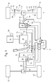
- a work vehicle 8 has a frame (not shown) or a self-supporting chassis supported on front wheels 10 and rear wheels 12 which are in engagement with the ground.
- the rear wheels 12 are generally steerable while the front wheels 10 are of larger diameter than the rear wheels 10 and support the greater part of the weight of the work vehicle 8, particularly when it is a harvester in the form of a combine harvester, cotton picker or self-propelled forage harvester is.
- the front wheels 10 are thus less traction-critical than the rear wheels 12.
- work machines such as tractors or sugar cane trailers with steerable front wheels, the positions of the rear and front wheels 12, 10 could be reversed.
- the drive system comprises a main engine 14 in the form of an internal combustion engine (diesel engine). Via a shaft 16, the main motor 14 drives a hydraulic pump 18 whose fluid displacement is variable by a swash plate 20. Their position can be changed by a driving lever 22, which is located in a driver's cab of the working vehicle 8.
- the hydraulic pump 18 has an outlet connected by lines 24 to the inlet of a first hydraulic motor 26 and the inlet of a second hydraulic motor 28.
- An inlet of the hydraulic pump 18 is connected via lines 30 to the outlet of the first hydraulic motor 26 and the outlet of the second hydraulic motor 28.
- the main motor 14 drives, if the work vehicle 8 is a self-propelled harvester, also their Gutbearbeitungs- or conveyors.
- the first hydraulic motor 26 drives the two rear wheels 12 via a first drive shaft 32 and a first self-locking differential gear 34.
- the second hydraulic motor 28 drives the two front wheels 10 via a second drive shaft 36 and a second self-locking differential 38.
- the first hydraulic motor 26 may optionally be switched on and off, so that a four-wheel drive is selectable only in special operating situations in which a better traction is needed.
- a manual transmission 37 is provided with different, selectable gear ratios.
- the translation stage of the gearbox 37 can - be changed manually in mechanical or electro-mechanical or electro-hydraulic manner - preferably while driving.
- a control device 40 is connected to a first rotational speed sensor 42, a second rotational speed sensor 44 and a first pressure sensor 46.
- the first speed sensor 42 is disposed adjacent to the first drive shaft 32 and outputs a pulse at each revolution (or several times during one revolution) of the first drive shaft 32.
- the second speed sensor 44 is mounted on the second drive shaft 36 on the output side of the transmission 37 and outputs at each revolution (or several times during one revolution) of the second drive shaft 36 from a pulse.
- the pressure sensor 46 is disposed in the interior of the first hydraulic motor 26 and detects the pressure applied to the outlet of the first hydraulic motor 26.
- the control device 40 is further connected to an electromechanical actuator 52, which is set up for adjusting a swash plate 54 of the first hydraulic motor 26. Information about the position of the actuator 52 may be fed back to the controller 40. If a stepper motor is used as actuator 52, this feedback is unnecessary.
- the second hydraulic motor 28 has a variable by an electromechanical actuator 56 and an adjustable swash plate 58 fluid displacement. Information about the position of the actuator 56 can be fed back to the control device 40.
- the second hydraulic motor 28 is a associated with the second pressure sensor 60, which measures the pressure at the outlet of the second hydraulic motor 28.
- the controller 40 is connected to the pressure sensor 60 and the actuator 56.
- a third actuator 62 is provided for adjusting the position of the swash plate 20 of the hydraulic pump 18, which operates electromechanically or electro-hydraulically and is controlled by the control device 40. It is conceivable to additionally supply the control device 40 with information about the respective position of the third actuator 62.
- a driving lever position sensor 48 serving as a speed setting device is assigned to the driving lever 22.
- the driving lever position sensor 48 detects the current position of the driving lever 22 optically or magnetically and transmits them to the control device 40.
- the control device 40 controls the actuators 52, 56 and 62 in normal operation in a manner known per se, that the working vehicle 8 moves at a speed that corresponds to the specification by the driving lever 22.
- the displacement volume of the swash plate 20 of the hydraulic pump 18 can be adjusted, for example, up to a certain limit speed proportional to the specification of the propulsion speed, while the displacement volumes of the swash plates 54, 58 of the hydraulic motors 26, 28 are set to their maximum value at speeds below the limit speed and, as soon as the displacement volume of the swash plate 20 of the hydraulic pump 18 has reached its maximum at the limit speed, at which the displacement volume of the swash plate 20 of the hydraulic pump 18 at higher speeds also remains reduced to an extent that leads to the achievement of the desired speed.
- the value of the limit speed depends on the selected gear ratio of the transmission 37.
- the controller 40 receives from the second speed sensor In addition, the controller 40 receives from the first speed sensor 42 information about the rotational speed of the rear wheels 12. Furthermore, the controller 40 information regarding the gear ratios between the shafts 32, 36, with which the speed sensors 42, 44 cooperate, and the wheels 10, 12 and with respect to the outer diameter of the wheels 10, 12 before.
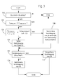
- control device 40 regularly performs a routine, as shown in FIG.
- the controller 40 calculates (step 100 in Fig. 2) a ratio of the peripheral speed of the front wheels 10 to the peripheral speed of the rear wheels 12. If the ratio is equal to 1 or deviates therefrom only insignificantly (step 102), no further action is required.
- step 104 If the ratio of the peripheral speed of the front wheels 10 to the peripheral speed of the rear wheels 12 is greater than 1 (step 104), it can be assumed that the front wheels 10 are spinning.
- the controller 40 then causes the actuator 56 (step 106) to move the wobble plate 58 to a position where the speed of the second hydraulic motor 28 is reduced, ie, its displacement volume is reduced.
- the control device 40 first checks (step 108) whether the displacement volume of the first hydraulic motor 26 is already at the maximum value. If this is not the case, the actuator 52 (step 110) is controlled such that it increases the displacement volume of the first hydraulic motor 26.
- the controller 40 causes the actuator 62 (step 112), the swashplate 20 of the hydraulic pump 18 in a position in which it provides a reduced hydraulic flow to the extent that the displacement capacity of the second hydraulic motor 28 is reduced.
- the swash plate 54 of the first hydraulic motor 26 is or is set to maximum displacement volume.
- the controller 40 then causes the actuator 52 (step 114) to move the wobble plate 54 to a position where the speed of the first hydraulic motor 26 is reduced. In this case, in order to keep the speed of the front wheels 10 constant, the controller 40 first checks (step 116) whether the displacement volume of the second hydraulic motor 28 is already at the maximum value. If this is not the case, the actuator 56 (step 118) is controlled such that it increases the displacement volume of the second hydraulic motor 28.
- the controller 40 causes the actuator 62 (step 112), the swashplate 20 of the hydraulic pump 18 to bring into a position in which they one in the extent Provides reduced hydraulic flow, in which the displacement capacity of the first hydraulic motor 26 is reduced.
- the swash plate 58 of the second hydraulic motor 26 is or is set to maximum displacement volume.
- this control strategy implies that there is a situation where the wheels of one axle have reduced ground contact while the wheels of the other axle are still in sufficient contact to transfer the available torque to the ground.
- the operating condition of the rear wheels 12 is monitored and controlled by a routine as shown in FIG.
- the control device 40 detects the pressure prevailing at the inlet of the first hydraulic motor 26 pressure by means of a further pressure sensor 49. This measured value is compared with the pressure at the outlet of the hydraulic motor 26 (step 120 in Figure 3), which is measured by the pressure sensor 46. The comparison allows determination of the operating state of the first hydraulic motor 26.
- the pressure at the inlet is greater than at the outlet, the first hydraulic motor 26 converts power and propels the work vehicle 8; the routine in Figure 3 ends according to. If the pressure at the inlet is less than at the outlet, the rear wheels 10 are in a dynamic braking situation, eg. B. when driving downhill.
- the controller 52 causes the swash plate 54 to move in the direction of lower speed adjusted (step 128).
- the degree of adjustment depends on the speed difference. If it exceeds a threshold of, for example, 30% (step 124), the hydraulic motor 26 is completely turned off (step 126). At very low speeds, this procedure is unnecessary.
- the adjustment of the swash plate 54 is in turn compensated by an adjustment of the swash plate 58 (step 132) in order to keep the traveling speed of the working vehicle 8 constant. If this is already at maximum displacement volume (step 130), the displacement volume of the hydraulic pump 18 is to be reduced analogously to the procedure illustrated in FIG. 2 (step 134). It should be noted that a corresponding monitoring of the front wheels 10 based on the pressure sensor 60 would also be possible.
- the illustrated routines are performed regularly, for. B. at intervals of a few milliseconds, and the described adjustments are reversed if no slip and no unwanted braking effect of the wheels 10 or 12 is present.
- a service brake is provided, each composed of a non-rotatably connected to the axis of the front wheels 10 brake disk 68 and a brake shoe 72 which can be pressed by a brake cylinder 70 against the brake disk 68.
- Each front wheel 10 and also each rear wheel 12 may be assigned its own service brake.
- the brake cylinder 70 is actuated hydraulically via a pedal arranged in the driver's cab, as a rule via a brake booster.
- the service brake is also effective in road driving operation, in which the driving speed can be predetermined by the driving lever 22 or an accelerator pedal.
- a parking brake actuator for actuating the parking brake brake cylinder 74 which is operable to press a brake shoe 76 against the brake disk 68.
- the brake shoe 76 and the Brake cylinder 74 are located on the side of the brake disc 68, which is the brake cylinder 70 and the brake shoe 72 opposite.
- Each front wheel 10 and also each rear wheel 12 may be assigned its own parking brake.
- the brake cylinder 74 is connected to the controller 40 and is driven by them.
- the parking brake is manually activated by the operator by means of a suitable switch connected to the control device 40 or by the control device 40 automatically when the work vehicle 8 is at a standstill in order to prevent undesired rolling away.
- the speed of the work vehicle 8 is, as already mentioned, controlled in the harvesting operation with the driving lever 22, while it is also specified in road driving by the driving lever 22 or an accelerator pedal.
- the controller 40 causes a motor controller 64 of the main motor 14 to reduce the rotational speed of the main motor 14 to reduce the fuel consumption.
- the control of the speed of the work vehicle 8 takes place at least during the harvesting operation, possibly also in road driving, exclusively by the driving lever 22. If an accelerator pedal is used for speed setting in road driving, it is also associated with the control device 40 sensor for detecting its position, corresponding to the accelerator position sensor 48, so that the accelerator pedal replaces the drive lever 22, while the remaining drive elements are controlled by the control device 40 as in the harvesting operation.
- a desired deceleration of the working vehicle 8 if the driving lever 22 or the accelerator pedal is moved in the direction of its neutral position, by the braking action of the hydraulic motors 26, 28.
- This braking effect is by parameters the hydraulic motors 26, 28 limited.
- the controller 40 activating the brake cylinder 74 of the parking brake.
- An activation of the brake cylinder or the parking brake 74 thus takes place when the time derivative of the position signal of the accelerator position sensor 48 (or a corresponding sensor for detecting the position of the accelerator pedal) is above a certain threshold.
- the brake cylinder 74 is controlled via a proportional valve 77, so that intermediate values of the braking effect can be achieved.
Applications Claiming Priority (2)
| Application Number | Priority Date | Filing Date | Title |
|---|---|---|---|
| DE102004016242A DE102004016242A1 (de) | 2004-04-02 | 2004-04-02 | Antriebssystem eines Arbeitsfahrzeugs |
| EP05102335A EP1582389B1 (fr) | 2004-04-02 | 2005-03-23 | Entraînement pour véhicule de travail |
Related Parent Applications (1)
| Application Number | Title | Priority Date | Filing Date |
|---|---|---|---|
| EP05102335A Division EP1582389B1 (fr) | 2004-04-02 | 2005-03-23 | Entraînement pour véhicule de travail |
Publications (2)
| Publication Number | Publication Date |
|---|---|
| EP1743823A1 true EP1743823A1 (fr) | 2007-01-17 |
| EP1743823B1 EP1743823B1 (fr) | 2008-05-28 |
Family
ID=34877705
Family Applications (2)
| Application Number | Title | Priority Date | Filing Date |
|---|---|---|---|
| EP05102335A Active EP1582389B1 (fr) | 2004-04-02 | 2005-03-23 | Entraînement pour véhicule de travail |
| EP06123361A Active EP1743823B1 (fr) | 2004-04-02 | 2005-03-23 | Entraînement pour véhicule de travail |
Family Applications Before (1)
| Application Number | Title | Priority Date | Filing Date |
|---|---|---|---|
| EP05102335A Active EP1582389B1 (fr) | 2004-04-02 | 2005-03-23 | Entraînement pour véhicule de travail |
Country Status (4)
| Country | Link |
|---|---|
| US (2) | US7240489B2 (fr) |
| EP (2) | EP1582389B1 (fr) |
| CA (1) | CA2503916C (fr) |
| DE (3) | DE102004016242A1 (fr) |
Cited By (1)
| Publication number | Priority date | Publication date | Assignee | Title |
|---|---|---|---|---|
| DE102020203524A1 (de) | 2020-03-19 | 2021-09-23 | Deere & Company | Dämpfung von Nickschwingungen eines Arbeitsfahrzeugs durch Geschwindigkeitsänderung und Verstellung eines Elements unter Berücksichtigung der Betriebsart |
Families Citing this family (28)
| Publication number | Priority date | Publication date | Assignee | Title |
|---|---|---|---|---|
| JP2007085405A (ja) * | 2005-09-20 | 2007-04-05 | Kobelco Cranes Co Ltd | 油圧駆動式作業車両の走行安定装置 |
| JP2007127174A (ja) | 2005-11-02 | 2007-05-24 | Hitachi Constr Mach Co Ltd | 作業車両の走行制御装置および走行制御方法 |
| US7974756B2 (en) | 2005-12-26 | 2011-07-05 | Komatsu Ltd. | Construction vehicle |
| GB0601142D0 (en) | 2006-01-20 | 2006-03-01 | Bamford Excavators Ltd | Working machine |
| GB2434421A (en) * | 2006-01-20 | 2007-07-25 | Bamford Excavators Ltd | A backhoe loader having ABS braking |
| DE102006041218A1 (de) * | 2006-02-10 | 2007-08-16 | Continental Teves Ag & Co. Ohg | Verfahren und Vorrichtung zum Betrieb eines Kraftfahrzeugs |
| GB2439333A (en) * | 2006-06-20 | 2007-12-27 | Bamford Excavators Ltd | Loading machine with ABS |
| US7798272B2 (en) | 2006-11-30 | 2010-09-21 | Caterpillar Inc | Systems and methods for controlling slip of vehicle drive members |
| US20090127018A1 (en) * | 2007-11-21 | 2009-05-21 | Caterpillar Paving Products Inc. | Component combination for a hydrostatically driven vehicle |
| US7849953B2 (en) * | 2007-11-29 | 2010-12-14 | Caterpillar Paving Products Inc | Control system and method for operating a hydrostatically driven vehicle |
| DE102007058535A1 (de) * | 2007-12-06 | 2009-06-10 | Deere & Company, Moline | Antriebssystem eines Arbeitsfahrzeugs |
| CN101480921A (zh) * | 2008-01-09 | 2009-07-15 | 三一重工股份有限公司 | 液压传动工程车辆抗滑转方法、系统以及平地机 |
| JP2010076748A (ja) | 2008-08-29 | 2010-04-08 | Kanzaki Kokyukoki Mfg Co Ltd | 車輌の走行系伝動構造 |
| US7748489B2 (en) * | 2008-10-31 | 2010-07-06 | Deere & Company | Agricultural header presence sensor with traction control |
| GB0915402D0 (en) * | 2009-09-04 | 2009-10-07 | Agco Gmbh | Tractors |
| DE102010021624A1 (de) | 2010-05-26 | 2011-12-01 | Robert Bosch Gmbh | Hydrostatischer Fahrantrieb |
| DE102013106047A1 (de) | 2012-12-17 | 2014-06-18 | Linde Material Handling Gmbh | Verfahren zur Antischlupfregelung eines hydrostatischen Fahrantriebs |
| EP2934976B1 (fr) * | 2012-12-20 | 2019-05-15 | CNH Industrial America LLC | Système et procédé permettant de commander le fonctionnement d'un véhicule de travail qui comporte une transmission de changement de puissance et un frein à main proportionnel |
| US9103425B2 (en) * | 2013-08-26 | 2015-08-11 | Caterpillar Inc. | Cost configurable hystat drive system |
| DE102013223988A1 (de) * | 2013-11-25 | 2015-05-28 | Deere & Company | Selbstfahrende Arbeitsmaschine mit hydrostatischem Fahrantrieb |
| BR112016020461B1 (pt) | 2014-03-03 | 2021-02-23 | Cnh Industrial Italia S.P.A. | veículo de trabalho |
| CA2927822A1 (fr) * | 2015-04-28 | 2016-10-28 | Option Industries Inc. | Systeme et methode de surveillance d'un treuil |
| DE102015209244A1 (de) | 2015-05-20 | 2016-11-24 | Avl Commercial Driveline & Tractor Engineering Gmbh | Verfahren zur Steuerung einer Raddrehzahl wenigstens eines Rades einer antreibbaren Achse eines zweispurigen Fahrzeugs mit zwei antreibbaren Achsen und zweispuriges Fahrzeug mit wenigstens zwei antreibbaren Achsen |
| US10011173B2 (en) | 2016-03-14 | 2018-07-03 | Caterpillar Inc. | Powertrain system for maintaining rimpull performance of machine |
| DE102017204353A1 (de) * | 2016-04-28 | 2017-11-02 | Robert Bosch Gmbh | Hydrostatischer Fahrantrieb und Verfahren zum Steuern des hydrostatischen Fahrantriebes |
| CN106900234B (zh) * | 2017-04-07 | 2023-04-07 | 农业农村部南京农业机械化研究所 | 一种插秧机的驱动系统 |
| US10464602B2 (en) | 2017-06-30 | 2019-11-05 | Cnh Industrial America Llc | Limited slip differential drive system and methods of using the same |
| CN113785695A (zh) * | 2021-10-11 | 2021-12-14 | 中国铁建重工集团股份有限公司 | 一种轮边液压驱动行走系统及采棉机 |
Citations (5)
| Publication number | Priority date | Publication date | Assignee | Title |
|---|---|---|---|---|
| DE2947552A1 (de) * | 1978-11-28 | 1980-06-04 | Komatsu Mfg Co Ltd | Hydraulikkreis fuer ein hydraulisch angetriebenes fahrzeug |
| US4301901A (en) * | 1980-03-21 | 1981-11-24 | J.I. Case Company | Combined foot brake and parking brake |
| EP0706466B1 (fr) * | 1993-07-03 | 1996-12-18 | Peter Lüpges | Dispositif de freinage |
| DE19607048A1 (de) * | 1996-02-24 | 1997-08-28 | Teves Gmbh Alfred | Bremsanlagen für ein motorgetriebenes Kraftfahrzeug und Verfahren zum Steuern dieser Bremsanlage |
| EP1223069A2 (fr) * | 2001-01-16 | 2002-07-17 | Brueninghaus Hydromatik Gmbh | Dispositif et procédé de commande de propulsion pour véhicule à transmission hydrostatique |
Family Cites Families (13)
| Publication number | Priority date | Publication date | Assignee | Title |
|---|---|---|---|---|
| SE423368B (sv) * | 1980-09-15 | 1982-05-03 | Volvo Flygmotor Ab | Forfarande for att forhindra slirning eller glidning mellan drivhjul och underlag vid serskilt fleraxliga fordonsdrivsystem med hydrostatisk kraftoverforing |
| US4399886A (en) * | 1980-12-09 | 1983-08-23 | Sundstrand Corporation | Controls for variable displacement motor and motors |
| DE3264966D1 (en) * | 1982-01-30 | 1985-09-05 | Losenhausen Maschinenbau Ag | Static displacement drive with by-pass circuit for towing |
| DE3727690A1 (de) * | 1987-08-19 | 1989-03-02 | Rexroth Mannesmann Gmbh | Schaltungsanordnung fuer den antrieb eines fahrzeuges |
| ATE133617T1 (de) * | 1993-10-29 | 1996-02-15 | Ec Eng & Consult Spezialmasch | Verfahren zum hydrostatischen antreiben eines fahrzeugs |
| US5775453A (en) * | 1995-09-20 | 1998-07-07 | Sauer Inc. | Traction control system and method for hydraulically propelled vehicles |
| US5924509A (en) * | 1997-03-19 | 1999-07-20 | Caterpillar Paving Products Inc. | Traction control apparatus and method for a hydrostatically driven work machine |
| US6321866B1 (en) * | 1998-10-21 | 2001-11-27 | Ag-Chem Equipment Co., Inc. | Hydrostatic power distribution/control logic system |
| DE19852039A1 (de) * | 1998-11-11 | 2000-05-25 | Sauer Sundstrand Gmbh & Co | Hydrostatisch angetriebenes Fahrzeug mit Retarderventileinrichtung |
| DE19939474C2 (de) * | 1999-08-20 | 2001-12-06 | Brueninghaus Hydromatik Gmbh | Hydrostatischer Fahrantrieb mit Antischlupfregelung |
| DE19956469A1 (de) * | 1999-11-24 | 2001-05-31 | Mannesmann Rexroth Ag | Hydrostatischer Fahrantrieb und Verfahren zum Betreiben des hydrostatischen Fahrantriebs |
| JP2002106711A (ja) * | 2000-10-02 | 2002-04-10 | Teijin Seiki Co Ltd | 走行用流体回路 |
| FR2865256B1 (fr) * | 2004-01-21 | 2010-12-17 | Komatsu Mfg Co Ltd | Regulateur pour vehicule equipe d'une boite de vitesses hydrostatique |
-
2004
- 2004-04-02 DE DE102004016242A patent/DE102004016242A1/de not_active Withdrawn
-
2005
- 2005-03-23 DE DE502005004282T patent/DE502005004282D1/de active Active
- 2005-03-23 EP EP05102335A patent/EP1582389B1/fr active Active
- 2005-03-23 DE DE502005001399T patent/DE502005001399D1/de active Active
- 2005-03-23 EP EP06123361A patent/EP1743823B1/fr active Active
- 2005-04-01 CA CA002503916A patent/CA2503916C/fr active Active
- 2005-04-01 US US11/097,842 patent/US7240489B2/en active Active
-
2007
- 2007-04-26 US US11/740,454 patent/US7540825B2/en active Active
Patent Citations (5)
| Publication number | Priority date | Publication date | Assignee | Title |
|---|---|---|---|---|
| DE2947552A1 (de) * | 1978-11-28 | 1980-06-04 | Komatsu Mfg Co Ltd | Hydraulikkreis fuer ein hydraulisch angetriebenes fahrzeug |
| US4301901A (en) * | 1980-03-21 | 1981-11-24 | J.I. Case Company | Combined foot brake and parking brake |
| EP0706466B1 (fr) * | 1993-07-03 | 1996-12-18 | Peter Lüpges | Dispositif de freinage |
| DE19607048A1 (de) * | 1996-02-24 | 1997-08-28 | Teves Gmbh Alfred | Bremsanlagen für ein motorgetriebenes Kraftfahrzeug und Verfahren zum Steuern dieser Bremsanlage |
| EP1223069A2 (fr) * | 2001-01-16 | 2002-07-17 | Brueninghaus Hydromatik Gmbh | Dispositif et procédé de commande de propulsion pour véhicule à transmission hydrostatique |
Cited By (1)
| Publication number | Priority date | Publication date | Assignee | Title |
|---|---|---|---|---|
| DE102020203524A1 (de) | 2020-03-19 | 2021-09-23 | Deere & Company | Dämpfung von Nickschwingungen eines Arbeitsfahrzeugs durch Geschwindigkeitsänderung und Verstellung eines Elements unter Berücksichtigung der Betriebsart |
Also Published As
| Publication number | Publication date |
|---|---|
| EP1743823B1 (fr) | 2008-05-28 |
| US7240489B2 (en) | 2007-07-10 |
| DE102004016242A1 (de) | 2005-10-20 |
| EP1582389A3 (fr) | 2006-02-01 |
| US7540825B2 (en) | 2009-06-02 |
| US20070187207A1 (en) | 2007-08-16 |
| EP1582389B1 (fr) | 2007-09-05 |
| CA2503916A1 (fr) | 2005-10-02 |
| CA2503916C (fr) | 2008-08-19 |
| DE502005001399D1 (de) | 2007-10-18 |
| US20050217261A1 (en) | 2005-10-06 |
| EP1582389A2 (fr) | 2005-10-05 |
| DE502005004282D1 (de) | 2008-07-10 |
Similar Documents
| Publication | Publication Date | Title |
|---|---|---|
| EP1743823B1 (fr) | Entraînement pour véhicule de travail | |
| EP2269880B1 (fr) | Frein d'une combinaison véhicule de traction-remorque | |
| EP1350658B1 (fr) | Système d'entraînement pour véhicule utilitaire | |
| EP3216333B1 (fr) | Tracteur agricole comprenant un véhicule tracteur et une remorque | |
| EP2384941A1 (fr) | Procédé de freinage et système de freinage d'un appareil freiné par une force étrangère | |
| EP1828643B1 (fr) | Procede pour freiner un vehicule entraine au moyen d'une boite de vitesses hydrostatique et boite de vitesses hydrostatique | |
| DE102016216587A1 (de) | System und verfahren zum reagieren auf radschlupf in einem zugfahrzeug | |
| EP2068045A2 (fr) | Système d'entraînement d'un véhicule de travail | |
| DE102014206123A1 (de) | Hydrostatischer Fahrantrieb in geschlossenem hydraulischen Kreis und Verfahren zur Steuerung des hydrostatischen Fahrantriebs | |
| EP2187101B1 (fr) | Système de propulsion pour un engin de construction autopropulsé | |
| EP0505727B1 (fr) | Transmission pour véhicules automobiles | |
| DE19830950A1 (de) | Verfahren und Vorrichtung zur Betätigung einer Kraftfahrzeug-Kupplungsvorrichtung | |
| EP1358784A1 (fr) | Véhicule agricole et procédé pour le régulation du glissement | |
| WO2005082664A1 (fr) | Procede pour faire fonctionner un arbre de prise de force couple a un moteur d'entrainement | |
| EP1308377A1 (fr) | Véhicule à chenilles | |
| DE4111921C2 (de) | Fahrzeug | |
| DE102018112042A1 (de) | Bremssystem für ein Arbeitsfahrzeug und Verfahren dafür | |
| DE10331367A1 (de) | Verfahren, Vorrichtung und deren Verwendung zum Betrieb eines Kraftfahrzeuges | |
| EP3461707A1 (fr) | Système de commande d'un dispositif de freinage à commande hydraulique | |
| EP2576266B1 (fr) | Organe de translation hydrostatique | |
| DE10027734A1 (de) | Hydrauliksystem zum Betätigen von wenigstens zwei Funktionsbereichen in einem Fahrzeug,vorzugsweise zum Lenken und Schalten eines Kraftfahrzeuges | |
| EP3738843B1 (fr) | Système hydraulique | |
| DE10310980B3 (de) | Fahrzeug | |
| DE10157506A1 (de) | Kraftfahrzeug und Vefahren zum Betreiben eines Kraftfahrzeuges | |
| DE10223296A1 (de) | Verfahren und Vorrichtung zur Steuerung von Fahrzeugen |
Legal Events
| Date | Code | Title | Description |
|---|---|---|---|
| PUAI | Public reference made under article 153(3) epc to a published international application that has entered the european phase |
Free format text: ORIGINAL CODE: 0009012 |
|
| AC | Divisional application: reference to earlier application |
Ref document number: 1582389 Country of ref document: EP Kind code of ref document: P |
|
| AK | Designated contracting states |
Kind code of ref document: A1 Designated state(s): AT BE BG CH CY CZ DE DK EE ES FI FR GB GR HU IE IS IT LI LT LU LV MC NL PL PT RO SE SI SK TR |
|
| AX | Request for extension of the european patent |
Extension state: AL BA HR LV MK YU |
|
| 17P | Request for examination filed |
Effective date: 20070717 |
|
| AKX | Designation fees paid |
Designated state(s): BE DE FR GB IT NL |
|
| GRAP | Despatch of communication of intention to grant a patent |
Free format text: ORIGINAL CODE: EPIDOSNIGR1 |
|
| GRAS | Grant fee paid |
Free format text: ORIGINAL CODE: EPIDOSNIGR3 |
|
| GRAA | (expected) grant |
Free format text: ORIGINAL CODE: 0009210 |
|
| AC | Divisional application: reference to earlier application |
Ref document number: 1582389 Country of ref document: EP Kind code of ref document: P |
|
| AK | Designated contracting states |
Kind code of ref document: B1 Designated state(s): BE DE FR GB IT NL |
|
| REG | Reference to a national code |
Ref country code: GB Ref legal event code: FG4D Free format text: NOT ENGLISH |
|
| REF | Corresponds to: |
Ref document number: 502005004282 Country of ref document: DE Date of ref document: 20080710 Kind code of ref document: P |
|
| PG25 | Lapsed in a contracting state [announced via postgrant information from national office to epo] |
Ref country code: NL Free format text: LAPSE BECAUSE OF FAILURE TO SUBMIT A TRANSLATION OF THE DESCRIPTION OR TO PAY THE FEE WITHIN THE PRESCRIBED TIME-LIMIT Effective date: 20080528 |
|
| NLV1 | Nl: lapsed or annulled due to failure to fulfill the requirements of art. 29p and 29m of the patents act | ||
| PLBE | No opposition filed within time limit |
Free format text: ORIGINAL CODE: 0009261 |
|
| STAA | Information on the status of an ep patent application or granted ep patent |
Free format text: STATUS: NO OPPOSITION FILED WITHIN TIME LIMIT |
|
| 26N | No opposition filed |
Effective date: 20090303 |
|
| REG | Reference to a national code |
Ref country code: FR Ref legal event code: PLFP Year of fee payment: 12 |
|
| REG | Reference to a national code |
Ref country code: FR Ref legal event code: PLFP Year of fee payment: 13 |
|
| REG | Reference to a national code |
Ref country code: FR Ref legal event code: PLFP Year of fee payment: 14 |
|
| REG | Reference to a national code |
Ref country code: DE Ref legal event code: R084 Ref document number: 502005004282 Country of ref document: DE |
|
| PGFP | Annual fee paid to national office [announced via postgrant information from national office to epo] |
Ref country code: FR Payment date: 20230327 Year of fee payment: 19 |
|
| PGFP | Annual fee paid to national office [announced via postgrant information from national office to epo] |
Ref country code: IT Payment date: 20230321 Year of fee payment: 19 Ref country code: BE Payment date: 20230327 Year of fee payment: 19 |
|
| PGFP | Annual fee paid to national office [announced via postgrant information from national office to epo] |
Ref country code: DE Payment date: 20240221 Year of fee payment: 20 Ref country code: GB Payment date: 20240327 Year of fee payment: 20 |