EP1743823A1 - Drive for a working vehicle - Google Patents
Drive for a working vehicle Download PDFInfo
- Publication number
- EP1743823A1 EP1743823A1 EP06123361A EP06123361A EP1743823A1 EP 1743823 A1 EP1743823 A1 EP 1743823A1 EP 06123361 A EP06123361 A EP 06123361A EP 06123361 A EP06123361 A EP 06123361A EP 1743823 A1 EP1743823 A1 EP 1743823A1
- Authority
- EP
- European Patent Office
- Prior art keywords
- actuator
- hydraulic motor
- displacement volume
- hydraulic
- speed
- Prior art date
- Legal status (The legal status is an assumption and is not a legal conclusion. Google has not performed a legal analysis and makes no representation as to the accuracy of the status listed.)
- Granted
Links
Images

Classifications
-
- B—PERFORMING OPERATIONS; TRANSPORTING
- B60—VEHICLES IN GENERAL
- B60K—ARRANGEMENT OR MOUNTING OF PROPULSION UNITS OR OF TRANSMISSIONS IN VEHICLES; ARRANGEMENT OR MOUNTING OF PLURAL DIVERSE PRIME-MOVERS IN VEHICLES; AUXILIARY DRIVES FOR VEHICLES; INSTRUMENTATION OR DASHBOARDS FOR VEHICLES; ARRANGEMENTS IN CONNECTION WITH COOLING, AIR INTAKE, GAS EXHAUST OR FUEL SUPPLY OF PROPULSION UNITS IN VEHICLES
- B60K17/00—Arrangement or mounting of transmissions in vehicles
- B60K17/04—Arrangement or mounting of transmissions in vehicles characterised by arrangement, location, or kind of gearing
- B60K17/10—Arrangement or mounting of transmissions in vehicles characterised by arrangement, location, or kind of gearing of fluid gearing
-
- B—PERFORMING OPERATIONS; TRANSPORTING
- B60—VEHICLES IN GENERAL
- B60W—CONJOINT CONTROL OF VEHICLE SUB-UNITS OF DIFFERENT TYPE OR DIFFERENT FUNCTION; CONTROL SYSTEMS SPECIALLY ADAPTED FOR HYBRID VEHICLES; ROAD VEHICLE DRIVE CONTROL SYSTEMS FOR PURPOSES NOT RELATED TO THE CONTROL OF A PARTICULAR SUB-UNIT
- B60W10/00—Conjoint control of vehicle sub-units of different type or different function
- B60W10/10—Conjoint control of vehicle sub-units of different type or different function including control of change-speed gearings
- B60W10/101—Infinitely variable gearings
- B60W10/103—Infinitely variable gearings of fluid type
-
- B—PERFORMING OPERATIONS; TRANSPORTING
- B60—VEHICLES IN GENERAL
- B60W—CONJOINT CONTROL OF VEHICLE SUB-UNITS OF DIFFERENT TYPE OR DIFFERENT FUNCTION; CONTROL SYSTEMS SPECIALLY ADAPTED FOR HYBRID VEHICLES; ROAD VEHICLE DRIVE CONTROL SYSTEMS FOR PURPOSES NOT RELATED TO THE CONTROL OF A PARTICULAR SUB-UNIT
- B60W10/00—Conjoint control of vehicle sub-units of different type or different function
- B60W10/18—Conjoint control of vehicle sub-units of different type or different function including control of braking systems
- B60W10/184—Conjoint control of vehicle sub-units of different type or different function including control of braking systems with wheel brakes
-
- B—PERFORMING OPERATIONS; TRANSPORTING
- B60—VEHICLES IN GENERAL
- B60W—CONJOINT CONTROL OF VEHICLE SUB-UNITS OF DIFFERENT TYPE OR DIFFERENT FUNCTION; CONTROL SYSTEMS SPECIALLY ADAPTED FOR HYBRID VEHICLES; ROAD VEHICLE DRIVE CONTROL SYSTEMS FOR PURPOSES NOT RELATED TO THE CONTROL OF A PARTICULAR SUB-UNIT
- B60W30/00—Purposes of road vehicle drive control systems not related to the control of a particular sub-unit, e.g. of systems using conjoint control of vehicle sub-units, or advanced driver assistance systems for ensuring comfort, stability and safety or drive control systems for propelling or retarding the vehicle
- B60W30/18—Propelling the vehicle
- B60W30/18009—Propelling the vehicle related to particular drive situations
- B60W30/18109—Braking
-
- F—MECHANICAL ENGINEERING; LIGHTING; HEATING; WEAPONS; BLASTING
- F16—ENGINEERING ELEMENTS AND UNITS; GENERAL MEASURES FOR PRODUCING AND MAINTAINING EFFECTIVE FUNCTIONING OF MACHINES OR INSTALLATIONS; THERMAL INSULATION IN GENERAL
- F16H—GEARING
- F16H61/00—Control functions within control units of change-speed- or reversing-gearings for conveying rotary motion ; Control of exclusively fluid gearing, friction gearing, gearings with endless flexible members or other particular types of gearing
- F16H61/38—Control of exclusively fluid gearing
- F16H61/40—Control of exclusively fluid gearing hydrostatic
- F16H61/4157—Control of braking, e.g. preventing pump over-speeding when motor acts as a pump
-
- F—MECHANICAL ENGINEERING; LIGHTING; HEATING; WEAPONS; BLASTING
- F16—ENGINEERING ELEMENTS AND UNITS; GENERAL MEASURES FOR PRODUCING AND MAINTAINING EFFECTIVE FUNCTIONING OF MACHINES OR INSTALLATIONS; THERMAL INSULATION IN GENERAL
- F16H—GEARING
- F16H61/00—Control functions within control units of change-speed- or reversing-gearings for conveying rotary motion ; Control of exclusively fluid gearing, friction gearing, gearings with endless flexible members or other particular types of gearing
- F16H61/38—Control of exclusively fluid gearing
- F16H61/40—Control of exclusively fluid gearing hydrostatic
- F16H61/42—Control of exclusively fluid gearing hydrostatic involving adjustment of a pump or motor with adjustable output or capacity
- F16H61/421—Motor capacity control by electro-hydraulic control means, e.g. using solenoid valves
-
- B—PERFORMING OPERATIONS; TRANSPORTING
- B60—VEHICLES IN GENERAL
- B60T—VEHICLE BRAKE CONTROL SYSTEMS OR PARTS THEREOF; BRAKE CONTROL SYSTEMS OR PARTS THEREOF, IN GENERAL; ARRANGEMENT OF BRAKING ELEMENTS ON VEHICLES IN GENERAL; PORTABLE DEVICES FOR PREVENTING UNWANTED MOVEMENT OF VEHICLES; VEHICLE MODIFICATIONS TO FACILITATE COOLING OF BRAKES
- B60T2201/00—Particular use of vehicle brake systems; Special systems using also the brakes; Special software modules within the brake system controller
- B60T2201/04—Hill descent control
-
- B—PERFORMING OPERATIONS; TRANSPORTING
- B60—VEHICLES IN GENERAL
- B60W—CONJOINT CONTROL OF VEHICLE SUB-UNITS OF DIFFERENT TYPE OR DIFFERENT FUNCTION; CONTROL SYSTEMS SPECIALLY ADAPTED FOR HYBRID VEHICLES; ROAD VEHICLE DRIVE CONTROL SYSTEMS FOR PURPOSES NOT RELATED TO THE CONTROL OF A PARTICULAR SUB-UNIT
- B60W2520/00—Input parameters relating to overall vehicle dynamics
- B60W2520/26—Wheel slip
-
- B—PERFORMING OPERATIONS; TRANSPORTING
- B60—VEHICLES IN GENERAL
- B60W—CONJOINT CONTROL OF VEHICLE SUB-UNITS OF DIFFERENT TYPE OR DIFFERENT FUNCTION; CONTROL SYSTEMS SPECIALLY ADAPTED FOR HYBRID VEHICLES; ROAD VEHICLE DRIVE CONTROL SYSTEMS FOR PURPOSES NOT RELATED TO THE CONTROL OF A PARTICULAR SUB-UNIT
- B60W2520/00—Input parameters relating to overall vehicle dynamics
- B60W2520/28—Wheel speed
-
- B—PERFORMING OPERATIONS; TRANSPORTING
- B60—VEHICLES IN GENERAL
- B60W—CONJOINT CONTROL OF VEHICLE SUB-UNITS OF DIFFERENT TYPE OR DIFFERENT FUNCTION; CONTROL SYSTEMS SPECIALLY ADAPTED FOR HYBRID VEHICLES; ROAD VEHICLE DRIVE CONTROL SYSTEMS FOR PURPOSES NOT RELATED TO THE CONTROL OF A PARTICULAR SUB-UNIT
- B60W2540/00—Input parameters relating to occupants
- B60W2540/10—Accelerator pedal position
- B60W2540/106—Rate of change
-
- F—MECHANICAL ENGINEERING; LIGHTING; HEATING; WEAPONS; BLASTING
- F16—ENGINEERING ELEMENTS AND UNITS; GENERAL MEASURES FOR PRODUCING AND MAINTAINING EFFECTIVE FUNCTIONING OF MACHINES OR INSTALLATIONS; THERMAL INSULATION IN GENERAL
- F16H—GEARING
- F16H59/00—Control inputs to control units of change-speed-, or reversing-gearings for conveying rotary motion
- F16H59/50—Inputs being a function of the status of the machine, e.g. position of doors or safety belts
- F16H2059/506—Wheel slip
-
- F—MECHANICAL ENGINEERING; LIGHTING; HEATING; WEAPONS; BLASTING
- F16—ENGINEERING ELEMENTS AND UNITS; GENERAL MEASURES FOR PRODUCING AND MAINTAINING EFFECTIVE FUNCTIONING OF MACHINES OR INSTALLATIONS; THERMAL INSULATION IN GENERAL
- F16H—GEARING
- F16H59/00—Control inputs to control units of change-speed-, or reversing-gearings for conveying rotary motion
- F16H59/36—Inputs being a function of speed
- F16H59/44—Inputs being a function of speed dependent on machine speed of the machine, e.g. the vehicle
-
- F—MECHANICAL ENGINEERING; LIGHTING; HEATING; WEAPONS; BLASTING
- F16—ENGINEERING ELEMENTS AND UNITS; GENERAL MEASURES FOR PRODUCING AND MAINTAINING EFFECTIVE FUNCTIONING OF MACHINES OR INSTALLATIONS; THERMAL INSULATION IN GENERAL
- F16H—GEARING
- F16H63/00—Control outputs from the control unit to change-speed- or reversing-gearings for conveying rotary motion or to other devices than the final output mechanism
- F16H63/40—Control outputs from the control unit to change-speed- or reversing-gearings for conveying rotary motion or to other devices than the final output mechanism comprising signals other than signals for actuating the final output mechanisms
- F16H63/48—Signals to a parking brake or parking lock; Control of parking locks or brakes being part of the transmission
-
- Y—GENERAL TAGGING OF NEW TECHNOLOGICAL DEVELOPMENTS; GENERAL TAGGING OF CROSS-SECTIONAL TECHNOLOGIES SPANNING OVER SEVERAL SECTIONS OF THE IPC; TECHNICAL SUBJECTS COVERED BY FORMER USPC CROSS-REFERENCE ART COLLECTIONS [XRACs] AND DIGESTS
- Y10—TECHNICAL SUBJECTS COVERED BY FORMER USPC
- Y10S—TECHNICAL SUBJECTS COVERED BY FORMER USPC CROSS-REFERENCE ART COLLECTIONS [XRACs] AND DIGESTS
- Y10S477/00—Interrelated power delivery controls, including engine control
- Y10S477/904—Control signal is acceleration
- Y10S477/905—Acceleration of throttle signal
Definitions
- the invention relates to a drive system of a work vehicle having a main motor which is drivingly connected to a hydraulic pump having a variable displacement volume by means of an actuator and having a hydraulic motor which is in driving connection with at least one wheel engaged with the ground, the actuator is connected to a control device, which is also connected to a sensor for detecting the position of a speed input device, in particular a driving lever, the control device is operable to set the actuator according to a speed specification of the speed setting device, and a wheel is in driving connection with a parking brake, the can be actuated by a parking brake actuator.
- Many work vehicles such as agricultural vehicles and harvesters, use hydraulic drives. They include a pump driven by an internal combustion engine and a hydraulic motor connected to the hydraulic fluid conducting hydraulic motor that drives one or more wheels.
- wheels of the front and rear axles are each driven by at least one hydraulic motor associated with the axles.
- These hydraulic motors are often equipped with adjustable displacement, as well as the associated hydraulic pump.
- An internal combustion engine drives the adjustable hydraulic pump, which is hydraulically fluidly connected to the adjustable hydraulic motors, each of which serves to drive an axle.
- the speed of the motors and the pressure at their inlet and outlet are measured.
- An electronic control unit is connected to a drive lever and controls the swash plates of the hydraulic motors and the hydraulic pump.
- the swing angles of the hydraulic pump and the hydraulic motors are set according to the speed setting of the Driving lever set. If the rotational speeds of the axles deviate from one another, which indicates slippage, the hydraulic motor on which slip occurs is in each case adjusted.
- the other hydraulic motor and the hydraulic pump are controlled to keep the traveling speed constant.
- To stop the drive lever is brought by the operator in a rest position, so that the swash plates are moved to rest positions.
- the braking effect of the hydraulic motor is not sufficient in all cases.
- the problem underlying the invention is seen to provide a drive system of a work vehicle in which an improved braking effect is made possible.
- the drive system of the work vehicle which may in particular be a self-propelled harvester, includes a main engine, which is typically an internal combustion engine.
- the main motor drives a hydraulic pump directly or indirectly, i. via interposed mechanical, hydraulic or any other gear.
- the hydraulic pump is connected via a hydraulic line to a hydraulic motor which mechanically drives at least one wheel in engagement with the ground - or a track.
- a controller is connected to a sensor which detects the position of a speed input device, e.g. B. a driving lever or an accelerator pedal.
- the control device is also connected to an actuator which adjusts the displacement volume of the hydraulic pump.
- the control device of the drive system of the working vehicle with a parking brake actuator. If the speed default device the parking brake is used as an additional brake to enhance the braking effect of the hydraulic motor or motors, relatively fast, ie at a speed exceeding a fixed threshold, towards the neutral position. In the case of an emergency braking thus a faster stopping of the machine is possible.
- the control of the parking brake actuator can be done via a proportional valve to allow intermediate values of the delay.
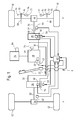
- a work vehicle 8 has a frame (not shown) or a self-supporting chassis supported on front wheels 10 and rear wheels 12 which are in engagement with the ground.
- the rear wheels 12 are generally steerable while the front wheels 10 are of larger diameter than the rear wheels 10 and support the greater part of the weight of the work vehicle 8, particularly when it is a harvester in the form of a combine harvester, cotton picker or self-propelled forage harvester is.
- the front wheels 10 are thus less traction-critical than the rear wheels 12.
- work machines such as tractors or sugar cane trailers with steerable front wheels, the positions of the rear and front wheels 12, 10 could be reversed.
- the drive system comprises a main engine 14 in the form of an internal combustion engine (diesel engine). Via a shaft 16, the main motor 14 drives a hydraulic pump 18 whose fluid displacement is variable by a swash plate 20. Their position can be changed by a driving lever 22, which is located in a driver's cab of the working vehicle 8.
- the hydraulic pump 18 has an outlet connected by lines 24 to the inlet of a first hydraulic motor 26 and the inlet of a second hydraulic motor 28.
- An inlet of the hydraulic pump 18 is connected via lines 30 to the outlet of the first hydraulic motor 26 and the outlet of the second hydraulic motor 28.
- the main motor 14 drives, if the work vehicle 8 is a self-propelled harvester, also their Gutbearbeitungs- or conveyors.
- the first hydraulic motor 26 drives the two rear wheels 12 via a first drive shaft 32 and a first self-locking differential gear 34.
- the second hydraulic motor 28 drives the two front wheels 10 via a second drive shaft 36 and a second self-locking differential 38.
- the first hydraulic motor 26 may optionally be switched on and off, so that a four-wheel drive is selectable only in special operating situations in which a better traction is needed.
- a manual transmission 37 is provided with different, selectable gear ratios.
- the translation stage of the gearbox 37 can - be changed manually in mechanical or electro-mechanical or electro-hydraulic manner - preferably while driving.
- a control device 40 is connected to a first rotational speed sensor 42, a second rotational speed sensor 44 and a first pressure sensor 46.
- the first speed sensor 42 is disposed adjacent to the first drive shaft 32 and outputs a pulse at each revolution (or several times during one revolution) of the first drive shaft 32.
- the second speed sensor 44 is mounted on the second drive shaft 36 on the output side of the transmission 37 and outputs at each revolution (or several times during one revolution) of the second drive shaft 36 from a pulse.
- the pressure sensor 46 is disposed in the interior of the first hydraulic motor 26 and detects the pressure applied to the outlet of the first hydraulic motor 26.
- the control device 40 is further connected to an electromechanical actuator 52, which is set up for adjusting a swash plate 54 of the first hydraulic motor 26. Information about the position of the actuator 52 may be fed back to the controller 40. If a stepper motor is used as actuator 52, this feedback is unnecessary.
- the second hydraulic motor 28 has a variable by an electromechanical actuator 56 and an adjustable swash plate 58 fluid displacement. Information about the position of the actuator 56 can be fed back to the control device 40.
- the second hydraulic motor 28 is a associated with the second pressure sensor 60, which measures the pressure at the outlet of the second hydraulic motor 28.
- the controller 40 is connected to the pressure sensor 60 and the actuator 56.
- a third actuator 62 is provided for adjusting the position of the swash plate 20 of the hydraulic pump 18, which operates electromechanically or electro-hydraulically and is controlled by the control device 40. It is conceivable to additionally supply the control device 40 with information about the respective position of the third actuator 62.
- a driving lever position sensor 48 serving as a speed setting device is assigned to the driving lever 22.
- the driving lever position sensor 48 detects the current position of the driving lever 22 optically or magnetically and transmits them to the control device 40.
- the control device 40 controls the actuators 52, 56 and 62 in normal operation in a manner known per se, that the working vehicle 8 moves at a speed that corresponds to the specification by the driving lever 22.
- the displacement volume of the swash plate 20 of the hydraulic pump 18 can be adjusted, for example, up to a certain limit speed proportional to the specification of the propulsion speed, while the displacement volumes of the swash plates 54, 58 of the hydraulic motors 26, 28 are set to their maximum value at speeds below the limit speed and, as soon as the displacement volume of the swash plate 20 of the hydraulic pump 18 has reached its maximum at the limit speed, at which the displacement volume of the swash plate 20 of the hydraulic pump 18 at higher speeds also remains reduced to an extent that leads to the achievement of the desired speed.
- the value of the limit speed depends on the selected gear ratio of the transmission 37.
- the controller 40 receives from the second speed sensor In addition, the controller 40 receives from the first speed sensor 42 information about the rotational speed of the rear wheels 12. Furthermore, the controller 40 information regarding the gear ratios between the shafts 32, 36, with which the speed sensors 42, 44 cooperate, and the wheels 10, 12 and with respect to the outer diameter of the wheels 10, 12 before.
- control device 40 regularly performs a routine, as shown in FIG.
- the controller 40 calculates (step 100 in Fig. 2) a ratio of the peripheral speed of the front wheels 10 to the peripheral speed of the rear wheels 12. If the ratio is equal to 1 or deviates therefrom only insignificantly (step 102), no further action is required.
- step 104 If the ratio of the peripheral speed of the front wheels 10 to the peripheral speed of the rear wheels 12 is greater than 1 (step 104), it can be assumed that the front wheels 10 are spinning.
- the controller 40 then causes the actuator 56 (step 106) to move the wobble plate 58 to a position where the speed of the second hydraulic motor 28 is reduced, ie, its displacement volume is reduced.
- the control device 40 first checks (step 108) whether the displacement volume of the first hydraulic motor 26 is already at the maximum value. If this is not the case, the actuator 52 (step 110) is controlled such that it increases the displacement volume of the first hydraulic motor 26.
- the controller 40 causes the actuator 62 (step 112), the swashplate 20 of the hydraulic pump 18 in a position in which it provides a reduced hydraulic flow to the extent that the displacement capacity of the second hydraulic motor 28 is reduced.
- the swash plate 54 of the first hydraulic motor 26 is or is set to maximum displacement volume.
- the controller 40 then causes the actuator 52 (step 114) to move the wobble plate 54 to a position where the speed of the first hydraulic motor 26 is reduced. In this case, in order to keep the speed of the front wheels 10 constant, the controller 40 first checks (step 116) whether the displacement volume of the second hydraulic motor 28 is already at the maximum value. If this is not the case, the actuator 56 (step 118) is controlled such that it increases the displacement volume of the second hydraulic motor 28.
- the controller 40 causes the actuator 62 (step 112), the swashplate 20 of the hydraulic pump 18 to bring into a position in which they one in the extent Provides reduced hydraulic flow, in which the displacement capacity of the first hydraulic motor 26 is reduced.
- the swash plate 58 of the second hydraulic motor 26 is or is set to maximum displacement volume.
- this control strategy implies that there is a situation where the wheels of one axle have reduced ground contact while the wheels of the other axle are still in sufficient contact to transfer the available torque to the ground.
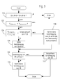
- the operating condition of the rear wheels 12 is monitored and controlled by a routine as shown in FIG.
- the control device 40 detects the pressure prevailing at the inlet of the first hydraulic motor 26 pressure by means of a further pressure sensor 49. This measured value is compared with the pressure at the outlet of the hydraulic motor 26 (step 120 in Figure 3), which is measured by the pressure sensor 46. The comparison allows determination of the operating state of the first hydraulic motor 26.
- the pressure at the inlet is greater than at the outlet, the first hydraulic motor 26 converts power and propels the work vehicle 8; the routine in Figure 3 ends according to. If the pressure at the inlet is less than at the outlet, the rear wheels 10 are in a dynamic braking situation, eg. B. when driving downhill.
- the controller 52 causes the swash plate 54 to move in the direction of lower speed adjusted (step 128).
- the degree of adjustment depends on the speed difference. If it exceeds a threshold of, for example, 30% (step 124), the hydraulic motor 26 is completely turned off (step 126). At very low speeds, this procedure is unnecessary.
- the adjustment of the swash plate 54 is in turn compensated by an adjustment of the swash plate 58 (step 132) in order to keep the traveling speed of the working vehicle 8 constant. If this is already at maximum displacement volume (step 130), the displacement volume of the hydraulic pump 18 is to be reduced analogously to the procedure illustrated in FIG. 2 (step 134). It should be noted that a corresponding monitoring of the front wheels 10 based on the pressure sensor 60 would also be possible.
- the illustrated routines are performed regularly, for. B. at intervals of a few milliseconds, and the described adjustments are reversed if no slip and no unwanted braking effect of the wheels 10 or 12 is present.
- a service brake is provided, each composed of a non-rotatably connected to the axis of the front wheels 10 brake disk 68 and a brake shoe 72 which can be pressed by a brake cylinder 70 against the brake disk 68.
- Each front wheel 10 and also each rear wheel 12 may be assigned its own service brake.
- the brake cylinder 70 is actuated hydraulically via a pedal arranged in the driver's cab, as a rule via a brake booster.
- the service brake is also effective in road driving operation, in which the driving speed can be predetermined by the driving lever 22 or an accelerator pedal.
- a parking brake actuator for actuating the parking brake brake cylinder 74 which is operable to press a brake shoe 76 against the brake disk 68.
- the brake shoe 76 and the Brake cylinder 74 are located on the side of the brake disc 68, which is the brake cylinder 70 and the brake shoe 72 opposite.
- Each front wheel 10 and also each rear wheel 12 may be assigned its own parking brake.
- the brake cylinder 74 is connected to the controller 40 and is driven by them.
- the parking brake is manually activated by the operator by means of a suitable switch connected to the control device 40 or by the control device 40 automatically when the work vehicle 8 is at a standstill in order to prevent undesired rolling away.
- the speed of the work vehicle 8 is, as already mentioned, controlled in the harvesting operation with the driving lever 22, while it is also specified in road driving by the driving lever 22 or an accelerator pedal.
- the controller 40 causes a motor controller 64 of the main motor 14 to reduce the rotational speed of the main motor 14 to reduce the fuel consumption.
- the control of the speed of the work vehicle 8 takes place at least during the harvesting operation, possibly also in road driving, exclusively by the driving lever 22. If an accelerator pedal is used for speed setting in road driving, it is also associated with the control device 40 sensor for detecting its position, corresponding to the accelerator position sensor 48, so that the accelerator pedal replaces the drive lever 22, while the remaining drive elements are controlled by the control device 40 as in the harvesting operation.
- a desired deceleration of the working vehicle 8 if the driving lever 22 or the accelerator pedal is moved in the direction of its neutral position, by the braking action of the hydraulic motors 26, 28.
- This braking effect is by parameters the hydraulic motors 26, 28 limited.
- the controller 40 activating the brake cylinder 74 of the parking brake.
- An activation of the brake cylinder or the parking brake 74 thus takes place when the time derivative of the position signal of the accelerator position sensor 48 (or a corresponding sensor for detecting the position of the accelerator pedal) is above a certain threshold.
- the brake cylinder 74 is controlled via a proportional valve 77, so that intermediate values of the braking effect can be achieved.
Abstract
Description
Die Erfindung betrifft ein Antriebssystem eines Arbeitsfahrzeugs mit einem Hauptmotor, der mit einer Hydraulikpumpe in Antriebsverbindung steht, die ein mittels eines Aktors veränderbares Verdrängungsvolumen aufweist und mit einem Hydraulikmotor, der mit wenigstens einem im Eingriff mit dem Erdboden befindlichen Rad in Antriebsverbindung steht, wobei der Aktor mit einer Steuerungseinrichtung verbunden ist, die auch mit einem Sensor zur Erfassung der Position einer Geschwindigkeitsvorgabeeinrichtung, insbesondere eines Fahrhebels, verbunden ist, die Steuerungseinrichtung betreibbar ist, den Aktor entsprechend einer Geschwindigkeitsvorgabe der Geschwindigkeitsvorgabeeinrichtung einzustellen, und ein Rad mit einer Parkbremse in Antriebsverbindung steht, die durch einen Parkbremsenaktor betätigbar ist.The invention relates to a drive system of a work vehicle having a main motor which is drivingly connected to a hydraulic pump having a variable displacement volume by means of an actuator and having a hydraulic motor which is in driving connection with at least one wheel engaged with the ground, the actuator is connected to a control device, which is also connected to a sensor for detecting the position of a speed input device, in particular a driving lever, the control device is operable to set the actuator according to a speed specification of the speed setting device, and a wheel is in driving connection with a parking brake, the can be actuated by a parking brake actuator.
Bei vielen Arbeitsfahrzeugen, wie landwirtschaftlichen Fahrzeugen und Erntemaschinen, werden hydraulische Antriebe eingesetzt. Sie umfassen eine durch einen Verbrennungsmotor angetriebene Pumpe und einen mit der Pumpe hydraulikflüssigkeitsleitend verbundenen Hydraulikmotor, der ein Rad oder mehrere Räder antreibt. Bei manchen Fahrzeugen werden Räder der Vorder- und Hinterachse durch jeweils mindestens einen, den Achsen zugeordneten Hydraulikmotor angetrieben. Diese Hydraulikmotore sind oftmals mit verstellbarem Verdrängungsvolumen ausgestattet, wie auch die zugehörige Hydraulikpumpe.Many work vehicles, such as agricultural vehicles and harvesters, use hydraulic drives. They include a pump driven by an internal combustion engine and a hydraulic motor connected to the hydraulic fluid conducting hydraulic motor that drives one or more wheels. In some vehicles, wheels of the front and rear axles are each driven by at least one hydraulic motor associated with the axles. These hydraulic motors are often equipped with adjustable displacement, as well as the associated hydraulic pump.
Ein derartiges Fahrzeug ist in der
Das der Erfindung zu Grunde liegende Problem wird darin gesehen, ein Antriebssystem eines Arbeitsfahrzeugs bereitzustellen, bei dem eine verbesserte Bremswirkung ermöglicht wird.The problem underlying the invention is seen to provide a drive system of a work vehicle in which an improved braking effect is made possible.
Dieses Problem wird erfindungsgemäß durch die Lehre des Patentanspruchs 1 gelöst, wobei in den weiteren Patentansprüchen Merkmale aufgeführt sind, die die Lösung in vorteilhafter Weise weiterentwickeln.This problem is inventively solved by the teaching of claim 1, wherein in the other claims features are listed, which further develop the solution in an advantageous manner.
Das Antriebssystem des Arbeitsfahrzeugs, bei dem es sich insbesondere um eine selbstfahrende Erntemaschine handeln kann, umfasst einen Hauptmotor, der in der Regel ein Verbrennungsmotor ist. Der Hauptmotor treibt eine Hydraulikpumpe direkt oder indirekt, d.h. über dazwischen geschaltete mechanische, hydraulische oder beliebige andere Getriebe an. Die Hydraulikpumpe steht über eine Hydraulikleitung mit einem Hydraulikmotor in Verbindung, der mindestens ein im Eingriff mit dem Erdboden befindliches Rad - oder eine Gleiskette - mechanisch antreibt. Eine Steuerungseinrichtung ist mit einem Sensor verbunden, der die Position einer Geschwindigkeitseingabeeinrichtung erfasst, z. B. eines Fahrhebels oder eines Gaspedals. Die Steuerungseinrichtung ist außerdem mit einem Aktor verbunden, der das Verdrängungsvolumen der Hydraulikpumpe verstellt.The drive system of the work vehicle, which may in particular be a self-propelled harvester, includes a main engine, which is typically an internal combustion engine. The main motor drives a hydraulic pump directly or indirectly, i. via interposed mechanical, hydraulic or any other gear. The hydraulic pump is connected via a hydraulic line to a hydraulic motor which mechanically drives at least one wheel in engagement with the ground - or a track. A controller is connected to a sensor which detects the position of a speed input device, e.g. B. a driving lever or an accelerator pedal. The control device is also connected to an actuator which adjusts the displacement volume of the hydraulic pump.
Es wird vorgeschlagen, die Steuerungseinrichtung des Antriebssystems des Arbeitsfahrzeugs mit einem Parkbremsenaktor zu verbinden. Falls die Geschwindigkeitsvorgabeeinrichtung relativ schnell, d. h. mit einer einen festgelegten Schwellenwert überschreitenden Geschwindigkeit, in Richtung auf die Neutralstellung bewegt wird, dient die Parkbremse als zusätzliche Bremse, um die Bremswirkung des Hydraulikmotors oder der Hydraulikmotore zu verstärken. Im Falle einer Notbremsung wird somit ein schnelleres Anhalten der Arbeitsmaschine möglich. Die Ansteuerung des Parkbremsaktors kann über ein Proportionalventil erfolgen, um auch Zwischenwerte der Verzögerung zu ermöglichen.It is proposed to connect the control device of the drive system of the working vehicle with a parking brake actuator. If the speed default device the parking brake is used as an additional brake to enhance the braking effect of the hydraulic motor or motors, relatively fast, ie at a speed exceeding a fixed threshold, towards the neutral position. In the case of an emergency braking thus a faster stopping of the machine is possible. The control of the parking brake actuator can be done via a proportional valve to allow intermediate values of the delay.
In den Zeichnungen ist ein nachfolgend näher beschriebenes Ausführungsbeispiel der Erfindung dargestellt. Es zeigt:
- Fig. 1
- ein Schema eines erfindungsgemäßen Antriebssystems,
- Fig. 2
- ein Flussdiagramm, gemäß dem die Steuerungseinrichtung bei Auftreten von Schlupf vorgeht, und
- Fig. 3
- ein Flussdiagramm, gemäß dem die Steuerungseinrichtung bei Auftreten einer Bremswirkung der hinteren Räder vorgeht.
- Fig. 1
- a diagram of a drive system according to the invention,
- Fig. 2
- a flowchart according to which the control device proceeds when slip occurs, and
- Fig. 3
- a flowchart according to which the control device proceeds when a braking effect of the rear wheels occurs.
In der Figur 1 ist eine Ausführungsform eines erfindungsgemäßen Antriebssystems schematisch dargestellt. Ein Arbeitsfahrzeug 8 weist einen (nicht dargestellten) Rahmen oder ein selbsttragendes Chassis auf, der sich auf vorderen Rädern 10 und hinteren Rädern 12 abstützt, die sich im Eingriff mit dem Erdboden befinden. Die hinteren Räder 12 sind in der Regel lenkbar, während die vorderen Räder 10 größeren Durchmessers als die hinteren Räder 10 sind und den größeren Teil des Gewichts des Arbeitsfahrzeugs 8 abstützen, insbesondere wenn es sich um eine Erntemaschine in Form eines Mähdreschers, Baumwollpflückers oder selbstfahrenden Feldhäckslers handelt. Die vorderen Räder 10 sind somit traktionsunkritischer als die hinteren Räder 12. Bei anderen Ausführungsformen von Arbeitsmaschinen, beispielsweise Traktoren oder Zuckerrohrerntern mit lenkbaren vorderen Rädern, könnten die Positionen der hinteren und vorderen Räder 12, 10 vertauscht sein.In the figure 1, an embodiment of a drive system according to the invention is shown schematically. A
Das Antriebssystem umfasst einen Hauptmotor 14 in Form eines Verbrennungsmotors (Dieselmotor). Über eine Welle 16 treibt der Hauptmotor 14 eine Hydraulikpumpe 18 an, deren Fluidverdrängung durch eine Taumelplatte 20 veränderbar ist. Deren Position ist durch einen Fahrhebel 22 veränderbar, welcher sich in einer Fahrerkabine des Arbeitsfahrzeugs 8 befindet. Die Hydraulikpumpe 18 weist einen Auslass auf, der durch Leitungen 24 mit dem Einlass eines ersten Hydraulikmotors 26 und dem Einlass eines zweiten Hydraulikmotors 28 verbunden ist. Ein Einlass der Hydraulikpumpe 18 ist über Leitungen 30 mit dem Auslass des ersten Hydraulikmotors 26 und dem Auslass des zweiten Hydraulikmotors 28 verbunden. Der Hauptmotor 14 treibt, falls das Arbeitsfahrzeug 8 eine selbstfahrende Erntemaschine ist, auch deren Gutbearbeitungs- bzw. Fördereinrichtungen an.The drive system comprises a
Der erste Hydraulikmotor 26 treibt über eine erste Antriebswelle 32 und ein erstes selbstsperrendes Differenzialgetriebe 34 die beiden hinteren Räder 12 an. Der zweite Hydraulikmotor 28 treibt über eine zweite Antriebswelle 36 und ein zweites selbstsperrendes Differenzialgetriebe 38 die beiden vorderen Räder 10 an. Der erste Hydraulikmotor 26 kann wahlweise ein- und ausschaltbar sein, so dass ein Vierradantrieb nur in besonderen Betriebssituationen auswählbar ist, in denen ein besseres Traktionsvermögen benötigt wird.The first
Zwischen dem zweiten Hydraulikmotor 28 und dem zweiten Differenzialgetriebe 38 ist ein Schaltgetriebe 37 mit unterschiedlichen, wählbaren Übersetzungsstufen vorhanden. Die Übersetzungsstufe des Schaltgetriebes 37 kann - vorzugsweise auch während der Fahrt - manuell auf mechanische oder elektromechanische bzw. elektrohydraulische Weise geändert werden.Between the second
Alternativ findet eine selbsttätige Umschaltung der Übersetzungsstufe des Getriebes statt, wie sie in der
Zum Rückwärtsfahren werden durch eine entsprechende Einstellung der Taumelplatte 20 der Hydraulikpumpe 18 die Flussrichtungen in den Leitungen 24 und 30 umgekehrt.For reversing the flow directions in the
Eine Steuerungseinrichtung 40 ist mit einem ersten Drehzahlsensor 42, einem zweiten Drehzahlsensor 44 und einem ersten Drucksensor 46 verbunden. Der erste Drehzahlsensor 42 ist der ersten Antriebswelle 32 benachbart angeordnet und gibt bei jeder Umdrehung (oder mehrmals während einer Umdrehung) der ersten Antriebswelle 32 einen Impuls ab. Der zweite Drehzahlsensor 44 ist an der zweiten Antriebswelle 36 ausgangsseitig des Schaltgetriebes 37 angebracht und gibt bei jeder Umdrehung (oder mehrmals während einer Umdrehung) der zweiten Antriebswelle 36 einen Impuls ab. Der Drucksensor 46 ist im Innenraum des ersten Hydraulikmotors 26 angeordnet und erfasst den Druck, der am Auslass des ersten Hydraulikmotors 26 anliegt.A
Die Steuerungseinrichtung 40 ist weiterhin mit einem elektromechanischen Aktor 52 verbunden, der zur Verstellung einer Taumelplatte 54 des ersten Hydraulikmotors 26 eingerichtet ist. Eine Information über die Stellung des Aktors 52 kann an die Steuerungseinrichtung 40 zurückgekoppelt werden. Findet ein Schrittmotor als Aktor 52 Verwendung, erübrigt sich diese Rückkopplung.The
Auch der zweite Hydraulikmotor 28 weist eine durch einen elektromechanischen Aktor 56 und eine verstellbare Taumelplatte 58 veränderbare Fluidverdrängung auf. Eine Information über die Stellung des Aktors 56 kann an die Steuerungseinrichtung 40 zurückgekoppelt werden. Dem zweiten Hydraulikmotor 28 ist ein zweiter Drucksensor 60 zugeordnet, der den Druck am Auslass des zweiten Hydraulikmotors 28 misst. Die Steuerungseinrichtung 40 ist mit dem Drucksensor 60 und dem Aktor 56 verbunden.Also, the second
Weiterhin ist ein dritter Aktor 62 zur Verstellung der Position der Taumelplatte 20 der Hydraulikpumpe 18 vorgesehen, der elektromechanisch oder elektrohydraulisch arbeitet und durch die Steuerungseinrichtung 40 gesteuert wird. Es ist denkbar, der Steuerungseinrichtung 40 zusätzlich eine Information über die jeweilige Stellung des dritten Aktors 62 zuzuführen.Furthermore, a
Ein als Geschwindigkeitsvorgabeeinrichtung dienender Fahrhebelstellungssensor 48 ist dem Fahrhebel 22 zugeordnet. Der Fahrhebelstellungssensor 48 erfasst die aktuelle Stellung des Fahrhebels 22 optisch oder magnetisch und übermittelt sie an die Steuerungseinrichtung 40.A driving
Die Steuerungseinrichtung 40 steuert die Aktoren 52, 56 und 62 in Normalbetrieb derart in an sich bekannter Weise an, dass sich das Arbeitsfahrzeug 8 mit einer Geschwindigkeit bewegt, die der Vorgabe durch den Fahrhebel 22 entspricht. Dabei kann das Verdrängungsvolumen der Taumelplatte 20 der Hydraulikpumpe 18 beispielsweise bis zu einer bestimmten Grenzgeschwindigkeit proportional zur Vorgabe der Vortriebsgeschwindigkeit eingestellt werden, während die Verdrängungsvolumina der Taumelplatten 54, 58 der Hydraulikmotore 26, 28 bei Geschwindigkeiten unter der Grenzgeschwindigkeit auf ihren Maximalwert gestellt werden und, sobald das Verdrängungsvolumen der Taumelplatte 20 der Hydraulikpumpe 18 bei der Grenzgeschwindigkeit sein Maximum erreicht hat, bei dem das Verdrängungsvolumen der Taumelplatte 20 der Hydraulikpumpe 18 bei höheren Geschwindigkeiten auch bleibt, in einem Maße reduziert werden, das zur Erreichung der gewünschten Geschwindigkeit führt. Der Wert der Grenzgeschwindigkeit hängt von der jeweils gewählten Übersetzungsstufe des Getriebes 37 ab.The
Die Steuerungseinrichtung 40 erhält vom zweiten Drehzahlsensor 44 einen Messwert hinsichtlich der Drehzahl der vorderen Räder 10. Außerdem erhält die Steuerungseinrichtung 40 vom ersten Drehzahlsensor 42 eine Information über die Drehzahl der hinteren Räder 12. Weiterhin liegen der Steuerungseinrichtung 40 Informationen hinsichtlich der Übersetzungsverhältnisse zwischen den Wellen 32, 36, mit denen die Drehzahlsensoren 42, 44 zusammenwirken, und den Rädern 10, 12 sowie hinsichtlich der äußeren Durchmesser der Räder 10, 12 vor.The
Um auch bei Betriebssituationen, in denen Schlupf an den Rädern auftritt, ein Durchdrehen der Räder 10, 12 zu verhindern, führt die Steuerungseinrichtung 40 regelmäßig eine Routine durch, wie sie in der Figur 2 dargestellt ist.In order to prevent spinning of the
Die Steuereinrichtung 40 berechnet (Schritt 100 in Figur 2) ein Verhältnis der Umfangsgeschwindigkeit der vorderen Räder 10 zur Umfangsgeschwindigkeit der hinteren Räder 12. Ist das Verhältnis gleich 1 oder weicht davon nur unwesentlich ab (Schritt 102), sind keine weiteren Maßnahmen erforderlich.The
Falls das Verhältnis der Umfangsgeschwindigkeit der vorderen Räder 10 zur Umfangsgeschwindigkeit der hinteren Räder 12 größer als 1 ist (Schritt 104), kann davon ausgegangen werden, dass die vorderen Räder 10 durchdrehen. Die Steuerungseinrichtung 40 veranlasst dann den Aktor 56 (Schritt 106), die Taumelplatte 58 in eine Stellung zu verbringen, in der die Geschwindigkeit des zweiten Hydraulikmotors 28 vermindert wird, d.h. sein Verdrängungsvolumen wird vermindert. Um in diesem Fall die Geschwindigkeit der hinteren Räder 12 konstant zu halten, prüft die Steuereinrichtung 40 zunächst ab (Schritt 108), ob das Verdrängungsvolumen des ersten Hydraulikmotors 26 schon auf dem Maximalwert ist. Falls das nicht der Fall ist, wird der Aktor 52 (Schritt 110) derart angesteuert, dass er das Verdrängungsvolumen des ersten Hydraulikmotors 26 vergrößert. Letzterer dreht sich somit langsamer und nimmt den zusätzlichen Hydraulikfluss auf, der durch die Verstellung der Taumelplatte 58 nicht mehr durch den zweiten Hydraulikmotor 28 aufgenommen werden kann. Ist die Taumelplatte 54 des ersten Hydraulikmotors 26 hingegen schon auf maximales Verdrängungsvolumen gestellt oder kann sie nicht in dem Maß verstellt werden, das erforderlich wäre, um das freiwerdende, zusätzliche Volumen aufzunehmen, veranlasst die Steuerungseinrichtung 40 den Aktor 62 (Schritt 112), die Taumelplatte 20 der Hydraulikpumpe 18 in eine Stellung zu bringen, in der sie einen in dem Maße verminderten Hydraulikfluss bereitstellt, in dem das Verdrängungsvermögen des zweiten Hydraulikmotors 28 vermindert wird. Die Taumelplatte 54 des ersten Hydraulikmotors 26 ist oder wird auf maximales Verdrängungsvolumen gestellt.If the ratio of the peripheral speed of the
Ist das Verhältnis der Umfangsgeschwindigkeit der vorderen Räder 10 zur Umfangsgeschwindigkeit der hinteren Räder 12 hingegen im Schritt 104 kleiner als 1, kann davon ausgegangen werden, dass die hinteren Räder durchdrehen. Die Steuerungseinrichtung 40 veranlasst dann den Aktor 52 (Schritt 114), die Taumelplatte 54 in eine Stellung zu verbringen, in der die Geschwindigkeit des ersten Hydraulikmotors 26 vermindert wird. Um in diesem Fall die Geschwindigkeit der vorderen Räder 10 konstant zu halten, prüft die Steuereinrichtung 40 zunächst (Schritt 116) ab, ob das Verdrängungsvolumen des zweiten Hydraulikmotors 28 schon auf dem Maximalwert ist. Falls das nicht der Fall ist, wird der Aktor 56 (Schritt 118) derart angesteuert, dass er das Verdrängungsvolumen des zweiten Hydraulikmotors 28 vergrößert. Letzterer dreht sich somit langsamer und nimmt den zusätzlichen Hydraulikfluss auf, der durch die Verstellung der Taumelplatte 54 nicht mehr durch den ersten Hydraulikmotor 26 aufgenommen werden kann. Ist die Taumelplatte 58 des zweiten Hydraulikmotors 28 hingegen schon auf maximales Verdrängungsvolumen gestellt oder kann sie nicht in dem Maß verstellt werden, das erforderlich wäre, um das freiwerdende, zusätzliche Volumen aufzunehmen, veranlasst die Steuerungseinrichtung 40 den Aktor 62 (Schritt 112), die Taumelplatte 20 der Hydraulikpumpe 18 in eine Stellung zu bringen, in der sie einen in dem Maße verminderten Hydraulikfluss bereitstellt, in dem das Verdrängungsvermögen des ersten Hydraulikmotors 26 vermindert wird. Die Taumelplatte 58 des zweiten Hydraulikmotors 26 ist oder wird auf maximales Verdrängungsvolumen gestellt.On the other hand, if the ratio of the peripheral speed of the
Diese Regelstrategie bedeutet physikalisch, dass man davon ausgeht, dass eine Situation vorliegt, in der die Räder einer Achse verminderten Bodenkontakt haben, während die Räder der anderen Achse noch hinreichenden Kontakt haben, um das verfügbare Drehmoment auf den Boden zu übertragen.Physically, this control strategy implies that there is a situation where the wheels of one axle have reduced ground contact while the wheels of the other axle are still in sufficient contact to transfer the available torque to the ground.
Der Betriebszustand der hinteren Räder 12 wird anhand einer Routine überwacht und gesteuert, wie sie in der Figur 3 dargestellt ist. Dabei erfasst die Steuerungseinrichtung 40 den am Einlass des ersten Hydraulikmotors 26 herrschenden Druck mittels eines weiteren Drucksensors 49. Dieser Messwert wird mit dem Druck am Auslass des Hydraulikmotors 26 verglichen (Schritt 120 in Figur 3), welcher durch den Drucksensor 46 gemessen wird. Der Vergleich erlaubt eine Bestimmung des Betriebszustands des ersten Hydraulikmotors 26. Wenn der Druck am Einlass größer als am Auslass ist, setzt der erste Hydraulikmotor 26 Leistung um und treibt das Arbeitsfahrzeug 8 voran; die Routine in Figur 3 endet dem gemäß. Ist der Druck am Einlass kleiner als am Auslass, befinden sich die hinteren Räder 10 in einer dynamischen Bremssituation, z. B. beim Bergabfahren. Um ein Durchdrehen der hinteren Räder 10 oder einen Backspin-Effekt zu vermeiden, veranlasst die Steuerungseinrichtung 40, falls sich die vorderen Räder 10 zusätzlich schneller als die hinteren Räder 12 drehen (Schritt 122), dass der Aktor 52 die Taumelplatte 54 in Richtung kleinerer Geschwindigkeit verstellt (Schritt 128). Das Maß der Verstellung hängt von der Geschwindigkeitsdifferenz ab. Falls diese einen Schwellenwert von beispielsweise 30 % überschreitet (Schritt 124), wird der Hydraulikmotor 26 ganz abgeschaltet (Schritt 126). Bei sehr kleinen Geschwindigkeiten erübrigt sich dieses Vorgehen.The operating condition of the
Die Verstellung der Taumelplatte 54 wird wiederum durch eine Verstellung der Taumelplatte 58 ausgeglichen (Schritt 132), um die Fahrgeschwindigkeit des Arbeitsfahrzeugs 8 konstant zu halten. Falls diese sich bereits bei maximalem Verdrängungsvolumen befindet (Schritt 130), ist analog zu der in Figur 2 dargestellten Vorgehensweise das Verdrängungsvolumen der Hydraulikpumpe 18 zu vermindern (Schritt 134). Anzumerken ist, dass eine entsprechende Überwachung der vorderen Räder 10 anhand des Drucksensors 60 ebenfalls möglich wäre.The adjustment of the
Die dargestellten Routinen werden regelmäßig durchgeführt, z. B. im Abstand einiger Millisekunden, und die erläuterten Verstellungen werden rückgängig gemacht, wenn kein Schlupf und keine unerwünschte Bremswirkung der Räder 10 oder 12 mehr vorliegt.The illustrated routines are performed regularly, for. B. at intervals of a few milliseconds, and the described adjustments are reversed if no slip and no unwanted braking effect of the
Um das Arbeitsfahrzeug im Gefahrenfall zügig anhalten zu können, ist eine Betriebsbremse vorgesehen, die sich jeweils aus einer drehfest mit der Achse der vorderen Räder 10 verbundenen Bremsscheibe 68 und einer Bremsbacke 72 zusammensetzt, die durch einen Bremszylinder 70 gegen die Bremsscheibe 68 gedrückt werden kann. Jedem Vorderrad 10 und auch jedem Hinterrad 12 kann eine eigene Betriebsbremse zugeordnet sein. Der Bremszylinder 70 wird hydraulisch über ein in der Fahrerkabine angeordnetes Pedal betätigt, in der Regel über einen Bremskraftverstärker. Die Betriebsbremse ist auch im Straßenfahrbetrieb wirksam, in dem die Fahrgeschwindigkeit durch den Fahrhebel 22 oder ein Gaspedal vorgebbar ist.In order to be able to quickly stop the work vehicle in case of danger, a service brake is provided, each composed of a non-rotatably connected to the axis of the
Zur Arretierung des Arbeitsfahrzeugs 8 im Stillstand ist weiterhin eine Parkbremse vorgesehen, die einen als Parkbremsenaktor zur Betätigung der Parkbremse dienenden Bremszylinder 74 umfasst, der betreibbar ist, eine Bremsbacke 76 gegen die Bremsscheibe 68 zu drücken. Die Bremsbacke 76 und der Bremszylinder 74 befinden sich auf der Seite der Bremsscheibe 68, die dem Bremszylinder 70 und der Bremsbacke 72 gegenüber liegt. Jedem Vorderrad 10 und auch jedem Hinterrad 12 kann eine eigene Parkbremse zugeordnet sein. Der Bremszylinder 74 ist mit der Steuerungseinrichtung 40 verbunden und wird durch sie angesteuert. Die Parkbremse wird durch den Bediener manuell mittels eines geeigneten, mit der Steuerungseinrichtung 40 verbundenen Schalters oder durch die Steuerungseinrichtung 40 selbsttätig bei Stillstand des Arbeitsfahrzeugs 8 aktiviert, um ein unerwünschtes Wegrollen zu verhindern.To lock the working
Die Geschwindigkeit des Arbeitsfahrzeugs 8 wird, wie bereits erwähnt, beim Erntebetrieb mit dem Fahrhebel 22 kontrolliert, während sie beim Straßenfahrbetrieb ebenfalls durch den Fahrhebel 22 oder ein Gaspedal vorgegeben wird. Im Straßenfahrbetrieb, der durch einen Ernte/Straßenfahrbetriebsschalter auswählbar ist oder anhand des Betriebszustands von Arbeitselementen des Arbeitsfahrzeugs 8 selbsttätig erkannt werden kann, veranlasst die Steuerungseinrichtung 40 eine Motorsteuerung 64 des Hauptmotors 14, die Drehzahl des Hauptmotors 14 zu vermindern, um den Betriebsstoffverbrauch zu reduzieren.The speed of the
Die Steuerung der Geschwindigkeit des Arbeitsfahrzeugs 8 erfolgt zumindest beim Erntebetrieb, ggf. auch im Straßenfahrbetrieb, ausschließlich durch den Fahrhebel 22. Falls im Straßenfahrbetrieb ein Gaspedal zur Geschwindigkeitsvorgabe verwendet wird, ist ihm ebenfalls ein mit der Steuerungseinrichtung 40 verbundener Sensor zur Erfassung seiner Position zugeordnet, entsprechend dem Fahrhebelstellungssensor 48, so dass das Gaspedal den Fahrhebel 22 ersetzt, während die übrigen Antriebselemente wie im Erntebetrieb durch die Steuerungseinrichtung 40 kontrolliert werden.The control of the speed of the
Eine gewünschte Verzögerung des Arbeitsfahrzeugs 8 erfolgt, falls der Fahrhebel 22 bzw. das Gaspedal in Richtung auf seine Neutralstellung bewegt wird, durch die Bremswirkung der Hydraulikmotoren 26, 28. Diese Bremswirkung ist durch Parameter der Hydraulikmotoren 26, 28 begrenzt. Falls der Fahrhebel 22 oder das Gaspedal relativ schnell in seine Neutralstellung bewegt wird, um das Arbeitsfahrzeug 8 beispielsweise im Notfall relativ schnell abstoppen zu können, wird eine vergrößerte Bremswirkung erzielt, indem die Steuerung 40 den bzw. die Bremszylinder 74 der Parkbremse aktiviert. Dadurch lässt sich das Arbeitsfahrzeug 8 relativ schnell anhalten. Eine Aktivierung des oder der Bremszylinder 74 der Parkbremse erfolgt somit, wenn die Zeitableitung des Positionssignals des Fahrhebelstellungssensors 48 (bzw. eines entsprechenden Sensors zur Erfassung der Position des Gaspedals) über einem bestimmten Schwellenwert liegt. Vorzugsweise wird der Bremszylinder 74 über ein Proportionalventil 77 angesteuert, so dass auch Zwischenwerte der Bremswirkung erzielbar sind.A desired deceleration of the working
Claims (3)
Applications Claiming Priority (2)
| Application Number | Priority Date | Filing Date | Title |
|---|---|---|---|
| DE102004016242A DE102004016242A1 (en) | 2004-04-02 | 2004-04-02 | Drive system of a work vehicle |
| EP05102335A EP1582389B1 (en) | 2004-04-02 | 2005-03-23 | Drive for a working vehicle |
Related Parent Applications (1)
| Application Number | Title | Priority Date | Filing Date |
|---|---|---|---|
| EP05102335A Division EP1582389B1 (en) | 2004-04-02 | 2005-03-23 | Drive for a working vehicle |
Publications (2)
| Publication Number | Publication Date |
|---|---|
| EP1743823A1 true EP1743823A1 (en) | 2007-01-17 |
| EP1743823B1 EP1743823B1 (en) | 2008-05-28 |
Family
ID=34877705
Family Applications (2)
| Application Number | Title | Priority Date | Filing Date |
|---|---|---|---|
| EP06123361A Active EP1743823B1 (en) | 2004-04-02 | 2005-03-23 | Drive for a working vehicle |
| EP05102335A Active EP1582389B1 (en) | 2004-04-02 | 2005-03-23 | Drive for a working vehicle |
Family Applications After (1)
| Application Number | Title | Priority Date | Filing Date |
|---|---|---|---|
| EP05102335A Active EP1582389B1 (en) | 2004-04-02 | 2005-03-23 | Drive for a working vehicle |
Country Status (4)
| Country | Link |
|---|---|
| US (2) | US7240489B2 (en) |
| EP (2) | EP1743823B1 (en) |
| CA (1) | CA2503916C (en) |
| DE (3) | DE102004016242A1 (en) |
Cited By (1)
| Publication number | Priority date | Publication date | Assignee | Title |
|---|---|---|---|---|
| DE102020203524A1 (en) | 2020-03-19 | 2021-09-23 | Deere & Company | Damping of pitching vibrations of a work vehicle by changing the speed and adjusting an element taking into account the operating mode |
Families Citing this family (28)
| Publication number | Priority date | Publication date | Assignee | Title |
|---|---|---|---|---|
| JP2007085405A (en) * | 2005-09-20 | 2007-04-05 | Kobelco Cranes Co Ltd | Travel stabilizing device for hydraulic drive type working vehicle |
| JP2007127174A (en) * | 2005-11-02 | 2007-05-24 | Hitachi Constr Mach Co Ltd | Apparatus and method for controlling travelling motion of working vehicle |
| JP4648407B2 (en) | 2005-12-26 | 2011-03-09 | 株式会社小松製作所 | Construction vehicle |
| GB0601142D0 (en) | 2006-01-20 | 2006-03-01 | Bamford Excavators Ltd | Working machine |
| GB2434421A (en) * | 2006-01-20 | 2007-07-25 | Bamford Excavators Ltd | A backhoe loader having ABS braking |
| DE102006041218A1 (en) * | 2006-02-10 | 2007-08-16 | Continental Teves Ag & Co. Ohg | Method and device for operating a motor vehicle |
| GB2439333A (en) * | 2006-06-20 | 2007-12-27 | Bamford Excavators Ltd | Loading machine with ABS |
| US7798272B2 (en) | 2006-11-30 | 2010-09-21 | Caterpillar Inc | Systems and methods for controlling slip of vehicle drive members |
| US20090127018A1 (en) * | 2007-11-21 | 2009-05-21 | Caterpillar Paving Products Inc. | Component combination for a hydrostatically driven vehicle |
| US7849953B2 (en) * | 2007-11-29 | 2010-12-14 | Caterpillar Paving Products Inc | Control system and method for operating a hydrostatically driven vehicle |
| DE102007058535A1 (en) * | 2007-12-06 | 2009-06-10 | Deere & Company, Moline | Drive system of a work vehicle |
| CN101480921A (en) * | 2008-01-09 | 2009-07-15 | 三一重工股份有限公司 | Hydraulic power transmission engineering vehicle antiskid method, system as well as leveler |
| JP2010076748A (en) | 2008-08-29 | 2010-04-08 | Kanzaki Kokyukoki Mfg Co Ltd | Traveling system transmission structure of vehicle |
| US7748489B2 (en) * | 2008-10-31 | 2010-07-06 | Deere & Company | Agricultural header presence sensor with traction control |
| GB0915402D0 (en) * | 2009-09-04 | 2009-10-07 | Agco Gmbh | Tractors |
| DE102010021624A1 (en) | 2010-05-26 | 2011-12-01 | Robert Bosch Gmbh | Hydrostatic drive |
| DE102013106047A1 (en) | 2012-12-17 | 2014-06-18 | Linde Material Handling Gmbh | Method for traction control of hydrostatic drive of e.g. industrial trucks, involves decreasing restriction amount of slipping motor and increasing restriction amount of non-slipping motor to correction restriction amount |
| WO2014099060A1 (en) * | 2012-12-20 | 2014-06-26 | Cnh America Llc | System and method for controlling the operation of a work vehicle having a power shift transmission and a proportional parking brake |
| US9103425B2 (en) | 2013-08-26 | 2015-08-11 | Caterpillar Inc. | Cost configurable hystat drive system |
| DE102013223988A1 (en) * | 2013-11-25 | 2015-05-28 | Deere & Company | Self-propelled working machine with hydrostatic drive |
| CN106104101B (en) | 2014-03-03 | 2018-05-01 | 凯斯纽荷兰(中国)管理有限公司 | Small wheel-type loading machine |
| CA2927822A1 (en) * | 2015-04-28 | 2016-10-28 | Option Industries Inc. | System and method for monitoring a winch |
| DE102015209244A1 (en) * | 2015-05-20 | 2016-11-24 | Avl Commercial Driveline & Tractor Engineering Gmbh | Method for controlling a wheel speed of at least one wheel of a drivable axle of a two-lane vehicle with two drivable axles and two-lane vehicle with at least two drivable axles |
| US10011173B2 (en) | 2016-03-14 | 2018-07-03 | Caterpillar Inc. | Powertrain system for maintaining rimpull performance of machine |
| DE102017204353A1 (en) * | 2016-04-28 | 2017-11-02 | Robert Bosch Gmbh | Hydrostatic drive and method for controlling the hydrostatic drive |
| CN106900234B (en) * | 2017-04-07 | 2023-04-07 | 农业农村部南京农业机械化研究所 | Driving system of rice transplanter |
| US10464602B2 (en) | 2017-06-30 | 2019-11-05 | Cnh Industrial America Llc | Limited slip differential drive system and methods of using the same |
| CN113785695A (en) * | 2021-10-11 | 2021-12-14 | 中国铁建重工集团股份有限公司 | Wheel limit hydraulic drive traveling system and cotton picker |
Citations (5)
| Publication number | Priority date | Publication date | Assignee | Title |
|---|---|---|---|---|
| DE2947552A1 (en) * | 1978-11-28 | 1980-06-04 | Komatsu Mfg Co Ltd | HYDRAULIC CIRCUIT FOR A HYDRAULICALLY DRIVED VEHICLE |
| US4301901A (en) * | 1980-03-21 | 1981-11-24 | J.I. Case Company | Combined foot brake and parking brake |
| EP0706466B1 (en) * | 1993-07-03 | 1996-12-18 | Peter Lüpges | Braking device |
| DE19607048A1 (en) * | 1996-02-24 | 1997-08-28 | Teves Gmbh Alfred | Automobile servo braking system |
| EP1223069A2 (en) * | 2001-01-16 | 2002-07-17 | Brueninghaus Hydromatik Gmbh | Device and method for propulsion control of a hydrostatically driven vehicle |
Family Cites Families (13)
| Publication number | Priority date | Publication date | Assignee | Title |
|---|---|---|---|---|
| SE423368B (en) * | 1980-09-15 | 1982-05-03 | Volvo Flygmotor Ab | PROCEDURE TO PREVENT SLIDING OR SLIDING BETWEEN DRIVE WHEELS AND SUBSTANCES OF SEPARATELY MULTI-AXIC VEHICLE DRIVE SYSTEM WITH HYDROSTATIC POWER TRANSMISSION |
| US4399886A (en) * | 1980-12-09 | 1983-08-23 | Sundstrand Corporation | Controls for variable displacement motor and motors |
| EP0085272B1 (en) * | 1982-01-30 | 1985-07-31 | Losenhausen Maschinenbau AG& Co Kommanditgesellschaft | Static displacement drive with by-pass circuit for towing |
| DE3727690A1 (en) * | 1987-08-19 | 1989-03-02 | Rexroth Mannesmann Gmbh | CIRCUIT ARRANGEMENT FOR DRIVING A VEHICLE |
| ATE133617T1 (en) * | 1993-10-29 | 1996-02-15 | Ec Eng & Consult Spezialmasch | METHOD FOR HYDROSTATICALLY DRIVING A VEHICLE |
| US5775453A (en) * | 1995-09-20 | 1998-07-07 | Sauer Inc. | Traction control system and method for hydraulically propelled vehicles |
| US5924509A (en) * | 1997-03-19 | 1999-07-20 | Caterpillar Paving Products Inc. | Traction control apparatus and method for a hydrostatically driven work machine |
| US6321866B1 (en) * | 1998-10-21 | 2001-11-27 | Ag-Chem Equipment Co., Inc. | Hydrostatic power distribution/control logic system |
| DE19852039A1 (en) * | 1998-11-11 | 2000-05-25 | Sauer Sundstrand Gmbh & Co | Vehicle with hydrostatic drive has retarder valve for hydraulically acquiring braking energy with connected pressure-limiting valve for choking output vol. flow of variable delivery pump |
| DE19939474C2 (en) * | 1999-08-20 | 2001-12-06 | Brueninghaus Hydromatik Gmbh | Hydrostatic drive with anti-slip control |
| DE19956469A1 (en) * | 1999-11-24 | 2001-05-31 | Mannesmann Rexroth Ag | Hydrostatic propulsive drive has braking device that interacts with each motor connected to control unit that activates brake if its associated motor's speed exceeds predetermined threshold |
| JP2002106711A (en) * | 2000-10-02 | 2002-04-10 | Teijin Seiki Co Ltd | Fluid circuit for traveling |
| FR2865256B1 (en) * | 2004-01-21 | 2010-12-17 | Komatsu Mfg Co Ltd | REGULATOR FOR A VEHICLE EQUIPPED WITH A HYDROSTATIC TRANSMISSION |
-
2004
- 2004-04-02 DE DE102004016242A patent/DE102004016242A1/en not_active Withdrawn
-
2005
- 2005-03-23 DE DE502005004282T patent/DE502005004282D1/en active Active
- 2005-03-23 EP EP06123361A patent/EP1743823B1/en active Active
- 2005-03-23 EP EP05102335A patent/EP1582389B1/en active Active
- 2005-03-23 DE DE502005001399T patent/DE502005001399D1/en active Active
- 2005-04-01 CA CA002503916A patent/CA2503916C/en active Active
- 2005-04-01 US US11/097,842 patent/US7240489B2/en active Active
-
2007
- 2007-04-26 US US11/740,454 patent/US7540825B2/en active Active
Patent Citations (5)
| Publication number | Priority date | Publication date | Assignee | Title |
|---|---|---|---|---|
| DE2947552A1 (en) * | 1978-11-28 | 1980-06-04 | Komatsu Mfg Co Ltd | HYDRAULIC CIRCUIT FOR A HYDRAULICALLY DRIVED VEHICLE |
| US4301901A (en) * | 1980-03-21 | 1981-11-24 | J.I. Case Company | Combined foot brake and parking brake |
| EP0706466B1 (en) * | 1993-07-03 | 1996-12-18 | Peter Lüpges | Braking device |
| DE19607048A1 (en) * | 1996-02-24 | 1997-08-28 | Teves Gmbh Alfred | Automobile servo braking system |
| EP1223069A2 (en) * | 2001-01-16 | 2002-07-17 | Brueninghaus Hydromatik Gmbh | Device and method for propulsion control of a hydrostatically driven vehicle |
Cited By (1)
| Publication number | Priority date | Publication date | Assignee | Title |
|---|---|---|---|---|
| DE102020203524A1 (en) | 2020-03-19 | 2021-09-23 | Deere & Company | Damping of pitching vibrations of a work vehicle by changing the speed and adjusting an element taking into account the operating mode |
Also Published As
| Publication number | Publication date |
|---|---|
| CA2503916C (en) | 2008-08-19 |
| DE502005004282D1 (en) | 2008-07-10 |
| EP1582389A2 (en) | 2005-10-05 |
| EP1582389A3 (en) | 2006-02-01 |
| EP1743823B1 (en) | 2008-05-28 |
| EP1582389B1 (en) | 2007-09-05 |
| US7240489B2 (en) | 2007-07-10 |
| DE502005001399D1 (en) | 2007-10-18 |
| DE102004016242A1 (en) | 2005-10-20 |
| US7540825B2 (en) | 2009-06-02 |
| US20050217261A1 (en) | 2005-10-06 |
| US20070187207A1 (en) | 2007-08-16 |
| CA2503916A1 (en) | 2005-10-02 |
Similar Documents
| Publication | Publication Date | Title |
|---|---|---|
| EP1743823B1 (en) | Drive for a working vehicle | |
| EP2269880B1 (en) | Brake for a traction vehicle trailer combination | |
| EP1350658B1 (en) | Drive system for working vehicle | |
| EP3216333B1 (en) | Agricultural train comprising a towing vehicle and a trailer | |
| EP2384941A1 (en) | Method for braking and braking system of an externally braked device | |
| EP1828643B1 (en) | Methods for braking a vehicle driven by a hydrostatic gearbox and a hydrostatic drive | |
| DE102016216587A1 (en) | SYSTEM AND METHOD FOR RESPONSE TO WHEEL SLIP IN A TRAIN VEHICLE | |
| EP2068045A2 (en) | Drive system of a work vehicle | |
| DE102014206123A1 (en) | Hydrostatic traction drive in closed hydraulic circuit and method for controlling the hydrostatic drive | |
| EP2187101B1 (en) | Propulsion system for self-proplled construction machine | |
| EP0505727B1 (en) | Drive mechanism for motor vehicles | |
| DE19830950A1 (en) | Method and device for actuating a motor vehicle clutch device | |
| EP1358784A1 (en) | Agricultural vehicle and method of regulating slip | |
| WO2005082664A1 (en) | Method for the operation of a traveling power take-off shaft coupled to a driving motor | |
| EP1308377A1 (en) | Tracked vehicle | |
| DE4111921C2 (en) | vehicle | |
| DE102018112042A1 (en) | Brake system for a work vehicle and method therefor | |
| DE10331367A1 (en) | Method, and use to drive motor vehicle with automated or automatic gears reduces engine torque during gear changes | |
| EP3461707A1 (en) | Control system of a hydraulically operated brake device | |
| EP2576266B1 (en) | Hydrostatic drive system | |
| DE10027734A1 (en) | Hydraulic system for actuating at least two functional areas in a vehicle, preferably for steering and switching a motor vehicle | |
| EP3738843B1 (en) | Hydraulic system | |
| DE10310980B3 (en) | Vehicle, especially tractor or vehicle with auxiliary drive, has second control device coupled to gas pedal and operated by gas pedal to control hydraulic pump's transport volume in working mode | |
| DE10157506A1 (en) | Motor vehicle has clutch with actuator that can be initially operated automatically by clutch controller and gearbox with which various gear ratios can be set | |
| DE10223296A1 (en) | Control of agricultural vehicles, supports changes in speed and direction of gear rotation using braking system, whilst bypassing starting clutch |
Legal Events
| Date | Code | Title | Description |
|---|---|---|---|
| PUAI | Public reference made under article 153(3) epc to a published international application that has entered the european phase |
Free format text: ORIGINAL CODE: 0009012 |
|
| AC | Divisional application: reference to earlier application |
Ref document number: 1582389 Country of ref document: EP Kind code of ref document: P |
|
| AK | Designated contracting states |
Kind code of ref document: A1 Designated state(s): AT BE BG CH CY CZ DE DK EE ES FI FR GB GR HU IE IS IT LI LT LU LV MC NL PL PT RO SE SI SK TR |
|
| AX | Request for extension of the european patent |
Extension state: AL BA HR LV MK YU |
|
| 17P | Request for examination filed |
Effective date: 20070717 |
|
| AKX | Designation fees paid |
Designated state(s): BE DE FR GB IT NL |
|
| GRAP | Despatch of communication of intention to grant a patent |
Free format text: ORIGINAL CODE: EPIDOSNIGR1 |
|
| GRAS | Grant fee paid |
Free format text: ORIGINAL CODE: EPIDOSNIGR3 |
|
| GRAA | (expected) grant |
Free format text: ORIGINAL CODE: 0009210 |
|
| AC | Divisional application: reference to earlier application |
Ref document number: 1582389 Country of ref document: EP Kind code of ref document: P |
|
| AK | Designated contracting states |
Kind code of ref document: B1 Designated state(s): BE DE FR GB IT NL |
|
| REG | Reference to a national code |
Ref country code: GB Ref legal event code: FG4D Free format text: NOT ENGLISH |
|
| REF | Corresponds to: |
Ref document number: 502005004282 Country of ref document: DE Date of ref document: 20080710 Kind code of ref document: P |
|
| PG25 | Lapsed in a contracting state [announced via postgrant information from national office to epo] |
Ref country code: NL Free format text: LAPSE BECAUSE OF FAILURE TO SUBMIT A TRANSLATION OF THE DESCRIPTION OR TO PAY THE FEE WITHIN THE PRESCRIBED TIME-LIMIT Effective date: 20080528 |
|
| NLV1 | Nl: lapsed or annulled due to failure to fulfill the requirements of art. 29p and 29m of the patents act | ||
| PLBE | No opposition filed within time limit |
Free format text: ORIGINAL CODE: 0009261 |
|
| STAA | Information on the status of an ep patent application or granted ep patent |
Free format text: STATUS: NO OPPOSITION FILED WITHIN TIME LIMIT |
|
| 26N | No opposition filed |
Effective date: 20090303 |
|
| REG | Reference to a national code |
Ref country code: FR Ref legal event code: PLFP Year of fee payment: 12 |
|
| REG | Reference to a national code |
Ref country code: FR Ref legal event code: PLFP Year of fee payment: 13 |
|
| REG | Reference to a national code |
Ref country code: FR Ref legal event code: PLFP Year of fee payment: 14 |
|
| REG | Reference to a national code |
Ref country code: DE Ref legal event code: R084 Ref document number: 502005004282 Country of ref document: DE |
|
| PGFP | Annual fee paid to national office [announced via postgrant information from national office to epo] |
Ref country code: FR Payment date: 20230327 Year of fee payment: 19 |
|
| PGFP | Annual fee paid to national office [announced via postgrant information from national office to epo] |
Ref country code: IT Payment date: 20230321 Year of fee payment: 19 Ref country code: GB Payment date: 20230327 Year of fee payment: 19 Ref country code: DE Payment date: 20230221 Year of fee payment: 19 Ref country code: BE Payment date: 20230327 Year of fee payment: 19 |