EP1308377A1 - Tracked vehicle - Google Patents
Tracked vehicle Download PDFInfo
- Publication number
- EP1308377A1 EP1308377A1 EP02020940A EP02020940A EP1308377A1 EP 1308377 A1 EP1308377 A1 EP 1308377A1 EP 02020940 A EP02020940 A EP 02020940A EP 02020940 A EP02020940 A EP 02020940A EP 1308377 A1 EP1308377 A1 EP 1308377A1
- Authority
- EP
- European Patent Office
- Prior art keywords
- tracked vehicle
- braking
- brake
- vehicle according
- pressure
- Prior art date
- Legal status (The legal status is an assumption and is not a legal conclusion. Google has not performed a legal analysis and makes no representation as to the accuracy of the status listed.)
- Granted
Links
Images


Classifications
-
- B—PERFORMING OPERATIONS; TRANSPORTING
- B62—LAND VEHICLES FOR TRAVELLING OTHERWISE THAN ON RAILS
- B62D—MOTOR VEHICLES; TRAILERS
- B62D5/00—Power-assisted or power-driven steering
- B62D5/001—Mechanical components or aspects of steer-by-wire systems, not otherwise provided for in this maingroup
- B62D5/003—Backup systems, e.g. for manual steering
-
- B—PERFORMING OPERATIONS; TRANSPORTING
- B60—VEHICLES IN GENERAL
- B60T—VEHICLE BRAKE CONTROL SYSTEMS OR PARTS THEREOF; BRAKE CONTROL SYSTEMS OR PARTS THEREOF, IN GENERAL; ARRANGEMENT OF BRAKING ELEMENTS ON VEHICLES IN GENERAL; PORTABLE DEVICES FOR PREVENTING UNWANTED MOVEMENT OF VEHICLES; VEHICLE MODIFICATIONS TO FACILITATE COOLING OF BRAKES
- B60T11/00—Transmitting braking action from initiating means to ultimate brake actuator without power assistance or drive or where such assistance or drive is irrelevant
- B60T11/10—Transmitting braking action from initiating means to ultimate brake actuator without power assistance or drive or where such assistance or drive is irrelevant transmitting by fluid means, e.g. hydraulic
- B60T11/16—Master control, e.g. master cylinders
- B60T11/20—Tandem, side-by-side, or other multiple master cylinder units
- B60T11/21—Tandem, side-by-side, or other multiple master cylinder units with two pedals operating on respective circuits, pressures therein being equalised when both pedals are operated together, e.g. for steering
-
- B—PERFORMING OPERATIONS; TRANSPORTING
- B60—VEHICLES IN GENERAL
- B60T—VEHICLE BRAKE CONTROL SYSTEMS OR PARTS THEREOF; BRAKE CONTROL SYSTEMS OR PARTS THEREOF, IN GENERAL; ARRANGEMENT OF BRAKING ELEMENTS ON VEHICLES IN GENERAL; PORTABLE DEVICES FOR PREVENTING UNWANTED MOVEMENT OF VEHICLES; VEHICLE MODIFICATIONS TO FACILITATE COOLING OF BRAKES
- B60T17/00—Component parts, details, or accessories of power brake systems not covered by groups B60T8/00, B60T13/00 or B60T15/00, or presenting other characteristic features
- B60T17/18—Safety devices; Monitoring
- B60T17/20—Safety devices operable by passengers other than the driver, e.g. for railway vehicles
-
- B—PERFORMING OPERATIONS; TRANSPORTING
- B60—VEHICLES IN GENERAL
- B60T—VEHICLE BRAKE CONTROL SYSTEMS OR PARTS THEREOF; BRAKE CONTROL SYSTEMS OR PARTS THEREOF, IN GENERAL; ARRANGEMENT OF BRAKING ELEMENTS ON VEHICLES IN GENERAL; PORTABLE DEVICES FOR PREVENTING UNWANTED MOVEMENT OF VEHICLES; VEHICLE MODIFICATIONS TO FACILITATE COOLING OF BRAKES
- B60T8/00—Arrangements for adjusting wheel-braking force to meet varying vehicular or ground-surface conditions, e.g. limiting or varying distribution of braking force
-
- B—PERFORMING OPERATIONS; TRANSPORTING
- B62—LAND VEHICLES FOR TRAVELLING OTHERWISE THAN ON RAILS
- B62D—MOTOR VEHICLES; TRAILERS
- B62D11/00—Steering non-deflectable wheels; Steering endless tracks or the like
- B62D11/02—Steering non-deflectable wheels; Steering endless tracks or the like by differentially driving ground-engaging elements on opposite vehicle sides
- B62D11/06—Steering non-deflectable wheels; Steering endless tracks or the like by differentially driving ground-engaging elements on opposite vehicle sides by means of a single main power source
- B62D11/08—Steering non-deflectable wheels; Steering endless tracks or the like by differentially driving ground-engaging elements on opposite vehicle sides by means of a single main power source using brakes or clutches as main steering-effecting means
-
- B—PERFORMING OPERATIONS; TRANSPORTING
- B62—LAND VEHICLES FOR TRAVELLING OTHERWISE THAN ON RAILS
- B62D—MOTOR VEHICLES; TRAILERS
- B62D11/00—Steering non-deflectable wheels; Steering endless tracks or the like
- B62D11/02—Steering non-deflectable wheels; Steering endless tracks or the like by differentially driving ground-engaging elements on opposite vehicle sides
- B62D11/06—Steering non-deflectable wheels; Steering endless tracks or the like by differentially driving ground-engaging elements on opposite vehicle sides by means of a single main power source
- B62D11/10—Steering non-deflectable wheels; Steering endless tracks or the like by differentially driving ground-engaging elements on opposite vehicle sides by means of a single main power source using gearings with differential power outputs on opposite sides, e.g. twin-differential or epicyclic gears
- B62D11/14—Steering non-deflectable wheels; Steering endless tracks or the like by differentially driving ground-engaging elements on opposite vehicle sides by means of a single main power source using gearings with differential power outputs on opposite sides, e.g. twin-differential or epicyclic gears differential power outputs being effected by additional power supply to one side, e.g. power originating from secondary power source
- B62D11/18—Steering non-deflectable wheels; Steering endless tracks or the like by differentially driving ground-engaging elements on opposite vehicle sides by means of a single main power source using gearings with differential power outputs on opposite sides, e.g. twin-differential or epicyclic gears differential power outputs being effected by additional power supply to one side, e.g. power originating from secondary power source the additional power supply being supplied hydraulically
- B62D11/183—Control systems therefor
-
- B—PERFORMING OPERATIONS; TRANSPORTING
- B62—LAND VEHICLES FOR TRAVELLING OTHERWISE THAN ON RAILS
- B62D—MOTOR VEHICLES; TRAILERS
- B62D55/00—Endless track vehicles
- B62D55/06—Endless track vehicles with tracks without ground wheels
Definitions
- the invention relates to a tracked vehicle with a drive system that Driving, braking, direction change and steering functions dependent of corresponding control commands from an electronic control unit performs.
- Such a tracked vehicle is for use on snow slopes generally known by corresponding snow groomers of the applicant.
- Such a known tracked vehicle is with a left as well provided with a right landing gear side, each with a chain drive exhibit.
- Every chain drive is driven by drive hydraulics, which has a hydraulic pump unit for each chassis side.
- the two hydraulic pump units are interposed a transfer case driven by an internal combustion engine, which can be designed as a diesel or gasoline engine.
- Every chain drive is assigned at least one drive wheel, each by a Hydromotor is driven, which is part of the drive hydraulics.
- Steering operations Acceleration and braking processes as well as changes of direction of travel due to switching from forward to The return trip is carried out by correspondingly different controls the hydraulic motors for the chain drives on both sides of the vehicle.
- the left and right side Chain drives can achieve steering movements.
- the control the hydraulic motors are made using corresponding hydraulic control means, which in turn is controlled by an electronic central control unit become.
- the object of the invention is a tracked vehicle of the type mentioned kind of creating that in the event of a failure or malfunction of the electronic control unit nevertheless controls the tracked vehicle allows.
- At least one currentless, separate braking system is provided, which in the case of exceeding or falling below at least one limit value of a function parameter the drive system by at least one currentless control element can be put into function.
- the braking system ensures that even in the event of an electronic failure, an electronic shutdown or an electronics malfunction or a vehicle controller, in particular braking to a standstill is possible. If that Drive system of the tracked vehicle has drive hydraulics, so is the function parameter in particular the pressure within the corresponding hydraulic circuit is decisive. Depending on Functional purpose, it is possible to set one or more pressure limits define above or below which the braking system passes the corresponding priority control is inevitably put into operation becomes.
- a suitable control element is for the hydraulic version
- the control element for the hydraulic version is pressure-dependent switching hydraulic valve.
- the braking system is at least one Function monitoring means assigned. Because the separate braking system not at all during normal operation of the tracked vehicle would be used, a failure of the brake system would not be without more can be recognized.
- the function monitoring means are for this provided to ensure that if the level is exceeded or fallen below corresponding limit values the safe functionality of the Brake system is given.
- the braking system preferably has Both sides of the vehicle have braking devices that are different Activation and consequently also enable steering processes.
- the braking system is at least one control element depending on exceeding or falling below different limit values of the function parameter from its idle mode in a steering function mode or in a braking function mode transferable. It is especially for the steering function mode necessary that the two vehicle sides of the tracked vehicle through the braking system can be controlled differently. This is preferable each vehicle side has its own braking device.
- the braking function mode is particularly necessary when the Braking force of a corresponding braking function of the drive system in itself no longer sufficient, in particular to meet the requirements one by a strong brake pedal pressure of a driver of the Track vehicle triggered brake pressure to meet.
- a steering function mode is particularly necessary in the event of vehicle electronics failure, in order to still be able to control the tracked vehicle.
- the drive system for Steering functions through electronic conversion of tax movements a manually operated control handle using the electronic Control unit is controllable
- the control handle is a mechanical effective coupling link assigned in the event of failure of the electronic Control unit can be activated by a positive actuator and the Control connection of the control handle to the drive system and / or the separate braking system. Since in this embodiment pure electronic transmission of control commands between the Control handle and the drive system is provided must be guaranteed be that the tracked vehicle even if the Electronics remains controllable. Thanks to the switchable mechanical coupling between the manually operated control handle and the drive system or the separate braking system are steering movements to achieve the tracked vehicle.
- each side of the undercarriage is independent of the drive hydraulics Brake device assigned, via at least one separate power supply circuit is fed, and the control handle is mechanical with at least one control element of the energy supply circuit connected, depending on a failure of the electronic Control unit can be switched on by means of a de-energized positive actuator and is dependent on corresponding steering movements
- Control handle controls the braking devices on both sides of the chassis.
- the energy supply circuit for the respective, from the drive hydraulics independent braking device can be electric, pneumatic or be designed hydraulically. Of course they are too Brake devices in a corresponding manner, electrically, pneumatically or integrated hydraulically.
- a hydraulic circuit is provided, which is fed by a pump device is that mechanically in connection with at least one chassis side stands that by the rolling motion of the tracked vehicle the Pump device is supplied with sufficient feed pressure. This ensures that there is sufficient supply pressure is that enables actuation of the brake system.
- the pumping device is dragged along with it, so with suitable coordination the at least one pump device on the brake system the desired feed pressure can be maintained.
- a pressure control valve is used as the control element provided that is proportional to the steering movements of the Control handle a control of both hydraulic circuits and the associated Makes braking devices. This is when driving straight ahead the pressure in both hydraulic circuits is kept the same. At a corresponding steering movement, the pressure in each hydraulic circuit lowered compared to the other hydraulic circuit, so that the desired braking device an appropriate braking function can perform, reducing the intended speed of the respective chain drive is effected.
- each braking device has a mechanically effective brake, in particular a multi-disc brake, that acts on a sprocket on the respective chassis side.
- This multi-disc brake is preferably with two brake pistons or brake discs provided independently can be controlled and each on a corresponding plate pack act.
- a function monitoring means at least one pressure sensor in the at least one energy supply circuit which integrates at least one braking device, which is connected to the electronic control unit.
- a hydraulic circuit is provided in this embodiment.
- function monitoring means the at least one energy supply circuit at least a pressure-dependent switchable actuator and the positive actuator a position sensor assigned to the electronic control unit are connected. This is the monitoring of the functionality of the braking system.
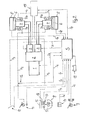
- a tracked vehicle K according to FIG. 1 is on two opposite vehicle sides each provided with a chain drive T.
- Each chain drive T has a revolving chain or caterpillar, which by a sprocket A is driven.
- the two chain drives T are each part of a chassis side.
- each chassis side has one Drive hydraulics described in more detail below, which are part of a Drive system in the sense of the invention and each on the as Driving wheel serving sprocket A acts on each chassis side.
- the Drive hydraulics for each chassis side have a hydraulic motor 4 on which by means of a gear 5 the sprocket A of the assigned Chain drive T drives.
- the drive hydraulics for each chassis side is provided with a pump unit 3 in the form of a hydraulic pump (Fig. 2).
- the two hydraulic pumps 3 are by means of a transfer case 2 driven by a central internal combustion engine 1.
- the internal combustion engine 1 is in the illustrated embodiment as Petrol engine executed. In the same way it is possible to use a diesel engine provided.
- Both the driving movements of the tracked vehicle K and changes in direction of travel are generated by an electronic control unit S, which controls the corresponding hydraulic pumps 3 of the respective drive hydraulics via control lines St.
- An accelerator pedal 9 which is connected to the electronic control unit S by means of a signal line S 5, is provided as a setpoint generator for a corresponding acceleration, maintenance or deceleration of the vehicle speed.
- a brake pedal 10 acts directly on a hydraulic brake circuit H 2 for severe decelerations, that is to say braking operations that cannot be implemented by correspondingly controlling the brake motors of the hydraulic motors.
- the hydraulic brake circuit comprises two brake devices 6, each of which is assigned to one side of the vehicle.
- the braking devices 6 are designed as multi-disc brakes and can be controlled by means of a brake piston 7a, which are part of the hydraulic brake circuit H 2 .
- the hydraulic brake circuit H 2 is set only if it exceeds a threshold pressure within the hydraulic brake circuit H 2 in function. In other brake pedal actuations which bring about a hydraulic pressure below 30 bar, the corresponding brake pressure is recorded via a pressure sensor 12 which is connected to the electronic control unit S by means of a signal line S 6 .
- This control unit S controls the corresponding hydraulic motors 4 accordingly in order to achieve the desired decelerations of the vehicle.
- the braking function is no longer carried out by actuating the hydraulic motors 4 via the electronic control unit S, but directly via the hydraulic circuit H 2 to the braking devices 6.
- the limit value or threshold value, beyond which the braking devices 6 come into operation, is 30 bar in the present exemplary embodiment.
- Each sprocket in the area of the transmission 5 is assigned the multi-disc brake 6 serving as a braking device, which is actuated via a spring-loaded air-releasing brake piston 7a.
- the spring force of the return spring of the brake piston 7a on each chassis side is designed in such a way that the multi-disc brake 6 is released up to the corresponding threshold value, in the present case 30 bar.
- the disk set of the disk brake 6 is compressed, as a result of which the desired braking function can be achieved on each chain wheel A and thus on the respective chain drive.
- the braking function above the predetermined threshold value which is independent of the electronic control unit S and thus also of a power supply, makes it possible to bring the vehicle to a standstill by appropriately pressing the brake pedal even if the electronic control unit S fails, is switched off or malfunctions.
- the brake pistons 7b can additionally be actuated by a parking brake 11, which in the present case is designed as a handbrake.
- a hydraulic line H 3 which is connected to the brake cylinders 7b, is assigned a control valve 20 serving as a control element, which releases or blocks the return flow to a tank 21 for the corresponding hydraulic oil.
- This threshold value represents the switching threshold for the brake pistons 7b, so that the pressure forces of the spring accumulator of each brake piston 7b exert a corresponding mechanical braking function on the corresponding multi-plate brake.
- the brake pistons 7b are provided independently of the brake pistons 7a and each act on the same multi-disc brake 6 as the associated one Brake piston 7a. Each multi-disc brake 6 is therefore double executed acting.
- the actuation of the brake pistons 7b has yet another essential function described below.
- the two hydraulic pumps 3 are controlled differently by the electronic control unit S.
- the electronic control unit S By reducing the speed of one hydraulic motor 4 or increasing the speed of each hydraulic motor 4, different speeds result for the two chain drives, whereby the desired steering process is achieved.
- the corresponding change in direction of travel is initiated by the steering movement of a control handle in the form of a steering wheel 8, the rotational movements of which are recorded by potentiometers 17.
- These are connected to the electronic control unit S via a signal line S 3 , so that the control unit S can detect every steering movement of the control handle 8 and convert it into the desired control command for the hydraulic pump 3.
- the tracked vehicle is provided with a hydraulic emergency steering 15.
- a further hydraulic circuit H 1 is provided, which acts on the multi-disc brakes 6 on both chassis sides, ie both chain drives, by means of the brake pistons 7b.
- the emergency steering system 15 has an electrically operated positive actuator, in the present case a solenoid valve, which is energized in normal operation, ie during the use of the electronic control unit S. This solenoid valve is integrated in the emergency steering valve 16 shown in FIG. 2.
- the hydraulic control element - likewise integrated in the emergency steering valve 16 - of the hydraulic circuit H 1 is activated.
- the hydraulic control element represents a pressure regulating valve which is controlled via a mechanical connection 19 by corresponding steering movements of the steering wheel 8.
- the pressure control valve within the emergency steering valve 16 reduces the pressure in one hydraulic circuit H 1 (FIG. 3) and / or increases or keeps it constant in the other hydraulic circuit H 1 .
- the system pressure required to hold the respective brake piston 7b in the released state against the spring force of a corresponding compression spring arrangement is defined at 15 bar.
- the multi-disc brake 6 has a braking function due to the spring force of the spring actuator now acting in the form of a compression spring arrangement, which acts on each brake piston 7b.
- the steering wheel 8 is held spring-centered in a zero position in order to facilitate control of the tracked vehicle.
- At least one feed pump 18 is provided, which is mechanically rotatably connected to a part rotating due to the movement of the tracked vehicle , This ensures that the at least one feed pump 18 is dragged along when the tracked vehicle rolls out, the pumping function of the at least one feed pump 18 being designed in such a way that the desired feed pressure of more than 15 bar is available as a result of this dragging process.
- the electronic control unit S is also assigned a plurality of signal or control lines S 7 to S 9 , which are described briefly below.
- the signal and control line S 7 is connected to engine electronics of the internal combustion engine 1 and enables the speed control of the internal combustion engine 1.
- the signal lines S 8 connect speed sensors on the chain wheels serving as drive wheels to the electronic control unit S. This provides feedback on the hydraulic motors 4 or brake pistons 7a, 7b actually achieved accelerations, decelerations or speeds and directions of travel, which enables an evaluation by means of the electronic control unit S.
- the data transmission line S 9 serves for function monitoring of the emergency steering 15, as will be explained in detail below with reference to the representations according to FIGS. 4 to 7.
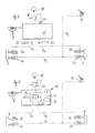
- FIGS. 4 and 6 or 5 and 7 correspond except for the differences described below based on 1 to 3 described embodiment.
- Significant difference in the embodiments according to FIGS. 4, 6 and 5, 7 it is that by means of these embodiments the previously with reference to FIGS. 1 to 3 Emergency steering function described in detail can be monitored. Thereby it is ensured that the electronic control unit S. Failure of the emergency steering function during normal driving of the Tracked vehicle can be recognized immediately. Because in normal operation the tracked vehicle is electronically steered so that a driver of the Tracked vehicle a possible failure of the hydraulic emergency steering can't notice. To ensure the functional fallback level for the The following is a breakdown of the electronic control described embodiments provided. Advantageously it is sufficient to carry out a corresponding functional check by the electronic control before each restart of the tracked vehicle perform.
- a detailed version of the emergency steering function is disclosed, which, apart from the monitoring means (described in more detail below), has a structure for the emergency steering function of the embodiment according to FIGS 1 to 3 can be used.
- the feed pump 18 is followed by two units.
- a steering unit 23 which is mechanically connected to the steering wheel 8 and, on the other hand, a release unit 25, which is a forced actuator that is automatically transferred to the functional position in the event of failure of the electronics.
- the steering unit 23 has two pressure reducers 23a and 23b, which are assigned to the right and left-hand hydraulic circuit H 1 for controlling the brake pistons 7b of the multi-disc brakes 6 on both sides of the vehicle.
- a 5/2-way valve is provided as a release unit or positive actuator 25, which valve is shown in its de-energized state in the illustration according to FIGS. 6 and 7. In the energized state, the lines, ie the hydraulic circuit H 1, are blocked. In this energized state, the line from the feed pump 18 takes place directly to the corresponding hydraulic motors 4.
- Each line H 1 is also assigned a 3/2-way valve which can be actuated together and either release the line to the brake pistons 7b or the return flow define these lines.
- two pressure sensors 22 are integrated in the lines H 1 near the multi-disc brakes 6, which can detect the line pressure in the two lines H 1 .
- an actuation switch is also in the Area of the handbrake 10 provided to the released or actuated To be able to detect the state of the handbrake 10.
- the pressure regulators or pressure reducers 23a, 23b reduce in the exemplary embodiment 4, 6 and also in the embodiment 5, 7 the feed pressure to about 14bar.
- the pressure increases right and falls left.
- the sinks Pressure to the right and rises to the left. This can be detected by the pressure sensors 22 become. If 14bar is not reached, one of the two is Pressure regulator 23a, 23b defective. This is particularly the case with one Spring breakage in one of the two pressure regulators 23a, 23b Obar.
- the handbrake When the 5/2-way valve 25 is energized, the handbrake is activated appropriate pressure adjusted. With the operating switch (previously described) the respective position of the handbrake can be detected. at open handbrake at a pump speed of preferably Higher than 900 revolutions per minute must have a feed pressure of 16 bar queue. The switching function is also used if a pressure sensor is defective of the positive actuator 25, i.e. of the 5/2-way valve, and the Pressure regulator 23a, 23b can still be monitored.
- the two Pressure regulator 23a, 23b monitored via two pressure switches 24.
- the ventilators The operating position of the handbrake is Monitored pressure switch, not shown.
- the position of the positive actuator in the form of the 5/2-way valve 25 via a position switch 26 recorded.
- the position switch 26 transmits the de-energized or energized position of the 5/2-way valve 25 to the electronic Control unit.
- the pressure switch causes a drop in pressure at the respective Pressure regulator 23a, 23b can be detected, so that in particular one Failure of a pressure regulator 23a, 23b can be seen.
- All of the function monitoring means described are electronic Control unit S coupled to that extent after a restart Issue a start approval for checking the corresponding functions or can refuse.
Abstract
Description
Die Erfindung betrifft ein Kettenfahrzeug mit einem Antriebssystem, das Fahr-, Brems-, Fahrtrichtungsänderungs- und Lenkfunktionen abhängig von entsprechenden Steuerbefehlen einer elektronischen Steuereinheit durchführt.The invention relates to a tracked vehicle with a drive system that Driving, braking, direction change and steering functions dependent of corresponding control commands from an electronic control unit performs.
Ein derartiges Kettenfahrzeug für den Einsatz auf Schneepisten ist durch entsprechende Pistenfahrzeuge der Anmelderin allgemein bekannt. Ein solches bekanntes Kettenfahrzeug ist mit einer linken sowie mit einer rechten Fahrwerkseite versehen, die jeweils einen Kettentrieb aufweisen. Jeder Kettentrieb wird durch eine Antriebshydraulik angetrieben, die für jede Fahrwerksseite jeweils eine Hydraulikpumpeinheit aufweist. Die beiden Hydraulikpumpeinheiten sind unter Zwischenschaltung eines Verteilergetriebes durch einen Verbrennungsmotor angetrieben, der als Diesel- oder als Ottomotor ausgeführt sein kann. Jedem Kettentrieb ist wenigstens ein Antriebsrad zugeordnet, das jeweils durch einen Hydromotor angetrieben wird, der Teil der Antriebshydraulik ist. Lenkvorgänge, Beschleunigungs- und Bremsvorgänge sowie Fahrtrichtungs-änderungsvorgänge aufgrund eines Umschaltens von Vorwärts- auf Rückfahrtsfahrt erfolgen durch entsprechend unterschiedliche Ansteuerung der Hydromotoren für die Kettentriebe auf beiden Fahrzeugseiten. Durch unterschiedliche Ansteuerung der links- und rechtsseitig angeordneten Kettentriebe sind Lenkbewegungen erzielbar. Die Ansteuerung der Hydromotoren erfolgt über entsprechend hydraulische Steuermittel, die wiederum durch eine elektronische zentrale Steuereinheit angesteuert werden.Such a tracked vehicle is for use on snow slopes generally known by corresponding snow groomers of the applicant. Such a known tracked vehicle is with a left as well provided with a right landing gear side, each with a chain drive exhibit. Every chain drive is driven by drive hydraulics, which has a hydraulic pump unit for each chassis side. The two hydraulic pump units are interposed a transfer case driven by an internal combustion engine, which can be designed as a diesel or gasoline engine. Every chain drive is assigned at least one drive wheel, each by a Hydromotor is driven, which is part of the drive hydraulics. Steering operations Acceleration and braking processes as well as changes of direction of travel due to switching from forward to The return trip is carried out by correspondingly different controls the hydraulic motors for the chain drives on both sides of the vehicle. By different control of the left and right side Chain drives can achieve steering movements. The control the hydraulic motors are made using corresponding hydraulic control means, which in turn is controlled by an electronic central control unit become.
Aufgabe der Erfindung ist es, ein Kettenfahrzeug der eingangs genannten Art zu schaffen, das bei einem Ausfall oder einer Fehlfunktion der elektronischen Steuereinheit dennoch eine Steuerung des Kettenfahrzeugs ermöglicht.The object of the invention is a tracked vehicle of the type mentioned Kind of creating that in the event of a failure or malfunction of the electronic control unit nevertheless controls the tracked vehicle allows.
Diese Aufgabe wird dadurch gelöst, dass wenigstens ein stromlos wirksames, separates Bremssystem vorgesehen ist, das bei Über- oder Unterschreiten wenigstens eines Grenzwertes eines Funktionsparameters des Antriebssystems durch wenigstens ein stromlos wirksames Steuerglied in Funktion versetzbar ist. Das Bremssystem gewährleistet, dass auch bei einem elektronischen Ausfall, einer elektronische Abschaltung oder eine Elektronikfehlfunktion noch eine Fahrzeugsteuerung, insbesondere ein Abbremsen zum Stillstand, möglich ist. Falls das Antriebssystem des Kettenfahrzeugs eine Antriebshydraulik aufweist, so ist als Funktionsparameter insbesondere der Druck innerhalb des entsprechenden Hydraulikkreislaufes maßgeblich. Je nach Funktionszweck ist es möglich, einen oder mehrere Druckgrenzwerte zu definieren, oberhalb oder unterhalb derer das Bremssystem durch entsprechende Zwangssteuerung zwangsläufig in Funktion versetzt wird. Ein geeignetes Steuerglied ist für die hydraulische Ausführung ein tes Steuerglied ist für die hydraulische Ausführung ein druckabhängig schaltendes Hydraulikventil.This object is achieved in that at least one currentless, separate braking system is provided, which in the case of exceeding or falling below at least one limit value of a function parameter the drive system by at least one currentless control element can be put into function. The braking system ensures that even in the event of an electronic failure, an electronic shutdown or an electronics malfunction or a vehicle controller, in particular braking to a standstill is possible. If that Drive system of the tracked vehicle has drive hydraulics, so is the function parameter in particular the pressure within the corresponding hydraulic circuit is decisive. Depending on Functional purpose, it is possible to set one or more pressure limits define above or below which the braking system passes the corresponding priority control is inevitably put into operation becomes. A suitable control element is for the hydraulic version The control element for the hydraulic version is pressure-dependent switching hydraulic valve.
In Ausgestaltung der Erfindung ist dem Bremssystem wenigstens ein Funktionsüberwachungsmittel zugeordnet. Da das separate Bremssystem im normalen Betrieb des Kettenfahrzeugs gegebenenfalls gar nicht zum Einsatz kommt, würde ein Ausfall des Bremssystems nicht ohne weiteres erkannt werden. Hierzu sind die Funktionsüberwachungsmittel vorgesehen, die gewährleisten, dass bei einem Über- oder Unterschreiten entsprechender Grenzwerte die sichere Funktionsfähigkeit des Bremssystems gegeben ist. Das Bremssystem weist vorzugsweise für beide Fahrzeugseiten Bremseinrichtungen auf, die eine unterschiedliche Ansteuerung und demzufolge auch Lenkvorgänge ermöglichen.In one embodiment of the invention, the braking system is at least one Function monitoring means assigned. Because the separate braking system not at all during normal operation of the tracked vehicle would be used, a failure of the brake system would not be without more can be recognized. The function monitoring means are for this provided to ensure that if the level is exceeded or fallen below corresponding limit values the safe functionality of the Brake system is given. The braking system preferably has Both sides of the vehicle have braking devices that are different Activation and consequently also enable steering processes.
In weiterer Ausgestaltung der Erfindung ist das Bremssystem durch das wenigstens eine Steuerglied abhängig von Über- oder Unterschreitung unterschiedlicher Grenzwerte des Funktionsparameters aus seinem Ruhemodus in einen Lenkfunktionsmodus oder in einen Bremsfunktionsmodus überführbar. Insbesondere für den Lenkfunktionsmodus ist es notwendig, dass die beiden Fahrzeugseiten des Kettenfahrzeugs durch das Bremssystem unterschiedlich ansteuerbar sind. Dazu ist vorzugsweise jeder Fahrzeugseite eine eigene Bremseinrichtung zugeordnet. Der Bremsfunktionsmodus ist insbesondere dann notwendig, wenn die Bremskraft einer entsprechenden Bremsfunktion des Antriebssystems für sich gesehen nicht mehr ausreicht, um insbesondere den Anforderungen eines durch einen starken Bremspedaldruck eines Fahrers des Kettenfahrzeugs ausgelösten Bremsdruckes zu genügen. Ein Lenkfunktionsmodus ist insbesondere beim Ausfall der Fahrzeugelektronik notwendig, um dennoch eine Steuerung des Kettenfahrzeugs zu ermöglichen. In a further embodiment of the invention, the braking system is at least one control element depending on exceeding or falling below different limit values of the function parameter from its idle mode in a steering function mode or in a braking function mode transferable. It is especially for the steering function mode necessary that the two vehicle sides of the tracked vehicle through the braking system can be controlled differently. This is preferable each vehicle side has its own braking device. The braking function mode is particularly necessary when the Braking force of a corresponding braking function of the drive system in itself no longer sufficient, in particular to meet the requirements one by a strong brake pedal pressure of a driver of the Track vehicle triggered brake pressure to meet. A steering function mode is particularly necessary in the event of vehicle electronics failure, in order to still be able to control the tracked vehicle.
In weiterer Ausgestaltung der Erfindung, wobei das Antriebssystem für Lenkfunktionen durch elektronische Umwandlung von Steuerbewegungen einer manuell bedienbaren Steuerhandhabe mittels der elektronischen Steuereinheit ansteuerbar ist, ist der Steuerhandhabe ein mechanisch wirksames Koppelglied zugeordnet, das beim Ausfall der elektronischen Steuereinheit durch ein Zwangsstellglied zuschaltbar ist und die Steuerverbindung der Steuerhandhabe zu dem Antriebssystem und/oder dem separaten Bremssystem herstellt. Da bei dieser Ausgestaltung eine reine elektronische Übertragung von Steuerbefehlen zwischen der Steuerhandhabe und dem Antriebssystem vorgesehen ist, muss gewährleistet sein, dass das Kettenfahrzeug auch bei einem Ausfall der Elektronik steuerfähig bleibt. Durch die zuschaltbare mechanische Kopplung zwischen der manuell bedienbaren Steuerhandhabe und dem Antriebssystem bzw. dem separaten Bremssystem sind Lenkbewegungen des Kettenfahrzeugs zu erzielen.In a further embodiment of the invention, the drive system for Steering functions through electronic conversion of tax movements a manually operated control handle using the electronic Control unit is controllable, the control handle is a mechanical effective coupling link assigned in the event of failure of the electronic Control unit can be activated by a positive actuator and the Control connection of the control handle to the drive system and / or the separate braking system. Since in this embodiment pure electronic transmission of control commands between the Control handle and the drive system is provided must be guaranteed be that the tracked vehicle even if the Electronics remains controllable. Thanks to the switchable mechanical coupling between the manually operated control handle and the drive system or the separate braking system are steering movements to achieve the tracked vehicle.
In weiterer Ausgestaltung der Erfindung ist als Teil des Bremssystems jeder Fahrwerksseite eine von der Antriebshydraulik unabhängige Bremseinrichtung zugeordnet, die über wenigstens einen separaten Energieversorgungskreis gespeist ist, und die Steuerhandhabe ist mechanisch mit wenigstens einem Steuerglied des Energieversorgungskreises verbunden, das abhängig von einem Ausfall der elektronischen Steuereinheit mittels eines stromlos wirksamen Zwangsstellgliedes zuschaltbar ist und abhängig von entsprechenden Lenkbewegungen der Steuerhandhabe die Bremseinrichtungen beider Fahrwerksseiten ansteuert. Der Energieversorgungskreis für die jeweilige, von der Antriebshydraulik unabhängige Bremseinrichtung kann elektrisch, pneumatisch oder hydraulisch ausgelegt sein. Selbstverständlich sind auch die Bremseinrichtungen in entsprechender Weise elektrisch, pneumatisch oder hydraulisch eingebunden. Durch die erfindungsgemäße Lösung ist gewährleistet, dass auch bei einem Ausfall oder einem Abschalten oder einer Fehlfunktion der Elektronik noch eine Lenkfunktion des Kettenfahrzeugs zumindest so lange geboten ist, bis das Kettenfahrzeug zum Stillstand gekommen ist. Durch diesen sicherheitstechnisch relevanten Aspekt ist eine Straßenzulassung für das Kettenfahrzeug trotz rein elektronischer Fahrtrichtungssteuerung ermöglicht.In a further embodiment of the invention is part of the braking system each side of the undercarriage is independent of the drive hydraulics Brake device assigned, via at least one separate power supply circuit is fed, and the control handle is mechanical with at least one control element of the energy supply circuit connected, depending on a failure of the electronic Control unit can be switched on by means of a de-energized positive actuator and is dependent on corresponding steering movements Control handle controls the braking devices on both sides of the chassis. The energy supply circuit for the respective, from the drive hydraulics independent braking device can be electric, pneumatic or be designed hydraulically. Of course they are too Brake devices in a corresponding manner, electrically, pneumatically or integrated hydraulically. By the solution according to the invention ensures that even in the event of a failure or a shutdown or a malfunction of the electronics or a steering function of the tracked vehicle at least until the tracked vehicle comes to a standstill has come. Through this safety-relevant aspect is a street legal for the tracked vehicle despite purely electronic Direction control enables.
In weiterer Ausgestaltung der Erfindung ist als Energieversorgungskreis ein Hydraulikkreis vorgesehen, der durch eine Pumpeinrichtung gespeist ist, die derart mechanisch mit wenigstens einer Fahrwerkseite in Verbindung steht, dass durch die Ausrollbewegung des Kettenfahrzeugs die Pumpeinrichtung mit einem ausreichenden Speisedruck versorgt wird. Dadurch ist gewährleistet, dass ein ausreichender Speisedruck vorhanden ist, der eine Betätigung des Bremssystems ermöglicht. Durch die mechanische Verbindung der wenigstens einen Pumpeinrichtung mit beim Ausrollen des Kettenfahrzeugs entsprechend rotierenden Teilen wird die Pumpeinrichtung mitgeschleppt, wodurch bei geeigneter Abstimmung der wenigstens einen Pumpeinrichtung auf das Bremssystem der gewünschte Speisedruck aufrecht erhalten werden kann.In a further embodiment of the invention is an energy supply circuit a hydraulic circuit is provided, which is fed by a pump device is that mechanically in connection with at least one chassis side stands that by the rolling motion of the tracked vehicle the Pump device is supplied with sufficient feed pressure. This ensures that there is sufficient supply pressure is that enables actuation of the brake system. Through the mechanical connection of the at least one pump device when rolling out the tracked vehicle corresponding rotating parts the pumping device is dragged along with it, so with suitable coordination the at least one pump device on the brake system the desired feed pressure can be maintained.
In weiterer Ausgestaltung der Erfindung ist als Steuerglied ein Druckregelventil vorgesehen, das proportional zu den Lenkbewegungen der Steuerhandhabe eine Ansteuerung beider Hydraulikkreise und der zugeordneten Bremseinrichtungen vornimmt. Dabei wird bei Geradeausfahrt der Druck in beiden Hydraulikkreisen gleich gehalten. Bei einer entsprechenden Lenkbewegung wird der Druck in jeweils einem Hydraulikkreis gegenüber dem anderen Hydraulikkreis abgesenkt, so dass die gewünschte Bremseinrichtung eine entsprechende Bremsfunktion durchführen kann, wodurch die beabsichtigte Geschwindigkeitsreduzierung des jeweiligen Kettentriebes bewirkt wird.In a further embodiment of the invention, a pressure control valve is used as the control element provided that is proportional to the steering movements of the Control handle a control of both hydraulic circuits and the associated Makes braking devices. This is when driving straight ahead the pressure in both hydraulic circuits is kept the same. At a corresponding steering movement, the pressure in each hydraulic circuit lowered compared to the other hydraulic circuit, so that the desired braking device an appropriate braking function can perform, reducing the intended speed of the respective chain drive is effected.
In weiterer Ausgestaltung der Erfindung weist jede Bremseinrichtung eine mechanisch wirksame Bremse, insbesondere eine Lamellenbremse, auf, die auf ein Kettenrad der jeweiligen Fahrwerksseite einwirkt. In a further embodiment of the invention, each braking device has a mechanically effective brake, in particular a multi-disc brake, that acts on a sprocket on the respective chassis side.
Dies ist eine besondere funktionssichere Ausgestaltung, die die Übertragung hoher Bremskräfte ermöglicht.This is a special functionally reliable design that the transmission high braking forces.
In weiterer Ausgestaltung der Erfindung ist eine doppelt wirkende Lamellenbremse vorgesehen. Diese Lamellenbremse ist vorzugsweise mit zwei Bremskolben oder Bremsscheiben versehen, die unabhängig voneinander ansteuerbar sind und jeweils auf ein entsprechendes Lamellenpaket einwirken.In a further embodiment of the invention is a double-acting multi-disc brake intended. This multi-disc brake is preferably with two brake pistons or brake discs provided independently can be controlled and each on a corresponding plate pack act.
In weiterer Ausgestaltung der Erfindung ist als Funktionsüberwachungsmittel wenigstens ein Drucksensor in dem wenigstens ein Energieversorgungskreis der wenigstens einen Bremseinrichtung integriert, der an die elektronische Steuereinheit angeschlossen ist. Als Energieversorgungsteil ist bei dieser Ausgestaltung ein Hydraulikkreis vorgesehen.In a further embodiment of the invention is a function monitoring means at least one pressure sensor in the at least one energy supply circuit which integrates at least one braking device, which is connected to the electronic control unit. As an energy supply part a hydraulic circuit is provided in this embodiment.
In weiterer Ausgestaltung der Erfindung sind als Funktionsüberwachungsmittel dem wenigstens einen Energieversorgungskreis wenigstens ein druckabhängig schaltbares Stellelement sowie dem Zwangsstellglied ein Positionssensor zugeordnet, die an die elektronische Steuereinheit angeschlossen sind. Somit ist die Überwachung der Funktionsfähigkeit des Bremssystem ermöglicht.In a further embodiment of the invention are function monitoring means the at least one energy supply circuit at least a pressure-dependent switchable actuator and the positive actuator a position sensor assigned to the electronic control unit are connected. This is the monitoring of the functionality of the braking system.
Weitere Vorteile und Merkmale der Erfindung ergeben sich aus den Ansprüchen sowie aus der nachfolgenden Beschreibung bevorzugter Ausführungsbeispiele der Erfindung, die anhand der Zeichnungen dargestellt sind.
- Fig. 1
- zeigt schematisch eine Ausführungsform eines erfindungsgemäßen Kettenfahrzeugs,
- Fig. 2
- in einem Blockschaltbild ein Antriebssystem für ein Kettenfahrzeug nach Fig. 1,
- Fig. 3
- in einer Schemadarstellung eine Ansteuerung für eine Notlenkfunktion eines Bremssystems für das Kettenfahrzeug nach Fig. 1,
- Fig. 4
- schematisch eine weitere Ausführungsform eines Bremssystems ähnlich Fig. 3,
- Fig. 5
- schematisch eine weitere Ausführungsform eines Bremssystems ähnlich Fig. 4,
- Fig. 6
- eine detaillierte Blockschaltdarstellung eines Teils des Brems-systems nach Fig. 4 und
- Fig. 7
- eine detaillierte Blockschaltdarstellung eines Teils des Brems-systems nach Fig. 5.
- Fig. 1
- schematically shows an embodiment of a tracked vehicle according to the invention,
- Fig. 2
- 1 shows a block diagram of a drive system for a tracked vehicle according to FIG. 1,
- Fig. 3
- 1 shows a control for an emergency steering function of a braking system for the tracked vehicle according to FIG. 1,
- Fig. 4
- schematically shows a further embodiment of a brake system similar to FIG. 3,
- Fig. 5
- schematically shows a further embodiment of a brake system similar to FIG. 4,
- Fig. 6
- a detailed block diagram of part of the brake system of FIG. 4 and
- Fig. 7
- 5 shows a detailed block diagram of part of the braking system according to FIG. 5.
Ein Kettenfahrzeug K nach Fig. 1 ist auf zwei gegenüberliegenden Fahrzeugseiten
mit jeweils einem Kettentrieb T versehen. Jeder Kettentrieb T
weist eine umlaufende Kette oder Raupe auf, die durch ein Kettenrad A
angetrieben ist. Die beiden Kettentriebe T sind jeweils Teil einer Fahrwerksseite.
Neben dem Kettentrieb T weist jede Fahrwerksseite eine
nachfolgend näher beschriebene Antriebshydraulik auf, die Teil eines
Antriebssystems im Sinne der Erfindung ist und die jeweils auf das als
Antriebsrad dienende Kettenrad A jeder Fahrwerksseite einwirkt. Die
Antriebshydraulik für jede Fahrwerksseite weist jeweils einen Hydromotor
4 auf, der mittels eines Getriebes 5 das Kettenrad A des zugeordneten
Kettentriebes T antreibt. Die Antriebshydraulik für jede Fahrwerksseite
ist mit jeweils einer Pumpeinheit 3 in Form einer Hydropumpe versehen
(Fig. 2). Die beiden Hydropumpen 3 sind mittels eines Verteilergetriebes
2 durch einen zentralen Verbrennungsmotor 1 angetrieben.
Der Verbrennungsmotor 1 ist beim dargestellten Ausführungsbeispiel als
Ottomotor ausgeführt. In gleicher Weise ist es möglich, einen Dieselmotor
vorzusehen.A tracked vehicle K according to FIG. 1 is on two opposite vehicle sides
each provided with a chain drive T. Each chain drive T
has a revolving chain or caterpillar, which by a sprocket A
is driven. The two chain drives T are each part of a chassis side.
In addition to the chain drive T, each chassis side has one
Drive hydraulics described in more detail below, which are part of a
Drive system in the sense of the invention and each on the as
Driving wheel serving sprocket A acts on each chassis side. The
Drive hydraulics for each chassis side have a hydraulic motor
4 on which by means of a
Sowohl die Fahrbewegungen des Kettenfahrzeugs K als auch Fahrtrichtungsänderungen
werden durch eine elektronische Steuereinheit S erzeugt,
die die entsprechenden Hydropumpen 3 der jeweiligen Antriebshydraulik
über Steuerleitungen St ansteuert. Für eine Beschleunigung
oder Verzögerung des Kettenfahrzeugs werden beide Hydropumpen 3
synchronisiert angesteuert, wodurch die beiden Hydromotoren 4 synchron
die Antriebsdrehzahlen stufenlos reduzieren oder erhöhen. Als
Sollwertgeber für eine entsprechende Beschleunigung, Konstanthaltung
oder Verzögerung der Fahrzeuggeschwindigkeit ist ein Fahrpedal 9 vorgesehen,
das mittels einer Signalleitung S5 mit der elektronischen Steuereinheit
S verbunden ist. Für starke Verzögerungen, d.h. Bremsvorgänge,
die durch entsprechende Bremspedalansteuerung der Hydromotoren
nicht realisierbar sind, wirkt ein Bremspedal 10 direkt auf einen
hydraulischen Bremskreis H2. Der hydraulische Bremskreis umfasst zwei
Bremseinrichtungen 6, die jeweils einer Fahrzeugseite zugeordnet sind.
Die Bremseinrichtungen 6 sind beim dargestellten Ausführungsbeispiel
als Lamellenbremse ausgeführt und mittels jeweils eines Bremskolbens
7a ansteuerbar, die Teil des hydraulischen Bremskreises H2 sind. Der
hydraulische Bremskreis H2 wird lediglich bei Überschreitung eines
Druckgrenzwertes innerhalb des hydraulischen Bremskreises H2 in
Funktion gesetzt. Bei anderen Bremspedalbetätigungen, die einen Hydraulikdruck
unter 30bar bewirken, wird der entsprechende Bremsdruck
über einen Drucksensor 12 aufgenommen, der mittels einer Signalleitung
S6 mit der elektronischen Steuereinheit S in Verbindung steht. Diese
Steuereinheit S steuert die entsprechenden Hydromotoren 4 entsprechend
an, um die gewünschten Verzögerungen des Fahrzeugs zu erreichen. Both the driving movements of the tracked vehicle K and changes in direction of travel are generated by an electronic control unit S, which controls the corresponding
Bei einer äußerst starken Verzögerung durch einen besonders starken
Druck auf das Bremspedal 10, bei dem ein Schwellwert oder Druckgrenzwert
des Systemdrucks innerhalb des hydraulischen Bremskreises
H2 überschritten wird, erfolgt die Bremsfunktion nicht mehr durch Ansteuerung
der Hydromotoren 4 über die elektronische Steuereinheit S,
sondern direkt über den Hydraulikkreis H2 auf die Bremseinrichtungen
6. Der Grenzwert oder Schwellwert, bei dessen Überschreitung die
Bremseinrichtungen 6 in Funktion treten, beträgt beim vorliegenden Ausführungsbeispiel
30bar. Jedem Kettenrad ist im Bereich des Getriebes 5
jeweils die als Bremseinrichtung dienende Lamellenbremse 6 zugeordnet,
die über einen federbelastet lüftenden Bremskolben 7a betätigt wird.
Die Federkraft der Rückstellfeder des Bremskolbens 7a auf jeder Fahrwerksseite
ist derart ausgelegt, dass die Lamellenbremse 6 bis zu dem
entsprechenden Schwellwert, vorliegend 30bar, gelüftet ist. Sobald ein
entsprechender Bremsdruck in dem Hydraulikkreis H2 diesen Schwellwert
von 30bar übersteigt, wird das Lamellenpaket der Lamellenbremse
6 zusammengedrückt, wodurch die gewünschte Bremsfunktion auf jedes
Kettenrad A und damit auf den jeweiligen Kettentrieb erzielbar ist.
Neben der alternativen Zuschaltung der Lamellenbremse anstelle des
jeweiligen Hydromotors 4 ist es auch möglich, über den Hydraulikkreis
H2 die jeweilige Lamellenbremse 6 ergänzend zur Wirkung des Hydromotors
4 einzusetzen. Durch die von der elektronischen Steuereinheit
S und damit auch von einer Stromversorgung unabhängige Bremsfunktion
oberhalb des vorgegebenen Schwellwertes ist es möglich, das Fahrzeug
durch entsprechend starke Betätigung des Bremspedals auch bei
Ausfall, Abschaltung oder Fehlfunktion der elektronischen Steuereinheit
S zum Stillstand zu bringen.In the event of an extremely strong deceleration due to a particularly strong pressure on the
Die Bremskolben 7b sind ergänzend durch eine Feststellbremse 11, die
vorliegend als Handbremse ausgeführt ist, betätigbar. Wie anhand der
Fig. 3 erkennbar ist, ist hierzu einer Hydraulikleitung H3, die mit den
Bremszylindern 7b in Verbindung steht, ein als Steuerglied dienendes
Stellventil 20 zugeordnet, das den Rücklauf zu einem Tank 21 für das
entsprechende Hydrauliköl freigibt oder sperrt. Bei geöffneter Handbremse
11 ist die als Federspeicher dienende Druckfederanordnung jedes
Bremszylinders 7b gelüftet, da dann die entsprechende Hydraulikleitung
druckbeaufschlagt ist. Bei einem Ziehen, d.h. Feststellen der
Handbremse 11 wird der Rücklauf zum Tank 21 durch entsprechende
Ansteuerung des Stellventils 20 freigegeben, wodurch sich der Druck in
der Hydraulikleitung H3 unter einen definierten Druckgrenzwert, vorliegend
unter einen Schwellwert von 15bar, reduziert. Dieser Schwellwert
stellt die Schaltschwelle für die Bremskolben 7b dar, so dass die Druckkräfte
des Federspeichers jedes Bremskolbens 7b eine entsprechende
mechanische Bremsfunktion auf die entsprechende Lamellenbremse
ausüben.The
Die Bremskolben 7b sind unabhängig von den Bremskolben 7a vorgesehen
und wirken jeweils auf die gleiche Lamellenbremse 6 wie der zugeordnete
Bremskolben 7a. Jede Lamellenbremse 6 ist somit doppelt
wirkend ausgeführt.The
Die Betätigung der Bremskolben 7b hat noch eine weitere, nachfolgend
beschriebene wesentliche Funktion. Für einen Lenkvorgang während
des normalen Betriebs des Kettenfahrzeugs werden die beiden Hydropumpen
3 durch die elektronische Steuereinheit S unterschiedlich angesteuert.
Durch die Reduzierung der Drehzahlen des einen Hydromotors
4 bzw. durch eine Erhöhung der Drehzahl jeweils eines Hydromotors 4
ergeben sich für die beiden Kettentriebe unterschiedliche Geschwindigkeiten,
wodurch der gewünschte Lenkvorgang erzielt wird. Initiiert wird
die entsprechende Fahrtrichtungsänderung durch die Lenkbewegung
einer Steuerhandhabe in Form eines Lenkrades 8, dessen Drehbewegungen
über Potentiometer 17 erfasst werden. Diese stehen über eine
Signalleitung S3 mit der elektronischen Steuereinheit S in Verbindung, so
dass die Steuereinheit S jede Lenkbewegung der Steuerhandhabe 8 erfassen
und in den gewünschten Steuerbefehl für die Hydropumpe 3 umsetzen
kann. Um auch noch bei einem entsprechenden Stromausfall,
einem Abschalten oder einer Fehlfunktion der Fahrzeugelektronik und
damit insbesondere der elektronischen Steuereinheit S, oder aus anderen
Ausfallgründen der Elektronik auch noch Lenkbewegungen zu gewährleisten,
ist das Kettenfahrzeug mit einer hydraulischen Notlenkung
15 versehen. Hierzu ist ein weiterer Hydraulikkreis H1 vorgesehen, der
mittels der Bremskolben 7b auf die Lamellenbremsen 6 beider Fahrwerksseiten,
d.h. beider Kettentriebe, wirkt. Um einen entsprechenden
Ausfall der Elektronik zu erkennen, weist das Notlenkungssystem 15 ein
elektrisch betätigtes Zwangsstellglied, vorliegend ein Magnetventil, auf,
das im Normalbetrieb, d.h. während des Einsatzes der elektronischen
Steuereinheit S, bestromt ist. Dieses Magnetventil ist in dem in Fig. 2
dargestellten Notlenkventil 16 integriert. Sobald das Magnetventil durch
den entsprechenden Spannungsabfall bei Ausfall oder Abschalten der
Fahrzeugelektronik stromlos geschaltet wird, wird das hydraulische
Steuerglied - ebenfalls im Notlenkventil 16 integriert - des Hydraulikkreises
H1 aktiviert. Das hydraulische Steuerglied stellt ein Druckregelventil
dar, das über eine mechanische Verbindung 19 durch entsprechende
Lenkbewegungen des Lenkrades 8 angesteuert wird. Je nach
Lenkbewegung wird mittels des Druckregelventils innerhalb des Notlenkventils
16 der Druck in dem einen Hydraulikkreis H1 (Fig. 3) reduziert
und/oder in dem anderen Hydraulikkreis H1 erhöht oder konstant gehalten.
Beim vorliegenden Ausführungsbeispiel ist der benötigte Systemdruck,
um den jeweiligen Bremskolben 7b im gelüfteten Zustand gegen
die Federkraft einer entsprechenden Druckfederanordnung zu halten,
bei 15bar definiert. Dies ist der Druckgrenzwert oder Schwellwert, der
die Schaltschwelle für die Lamellenbremse 6 auf jeder Fahrzeugseite
darstellt. Sobald der Druck unter diesen Schwellwert abfällt, ergibt sich
für die Lamellenbremse 6 eine Bremsfunktion aufgrund der Federkraft
des nun wirkenden Federspeichers in Form einer Druckfederanordnung,
die auf jeden Bremskolben 7b wirkt. Das Lenkrad 8 wird in einer Nulllage
federzentriert gehalten, um eine Steuerung des Kettenfahrzeugs zu
erleichtern.The actuation of the
Um zu gewährleisten, dass in den Hydraulikleitungen H1 ein ausreichender
Speisedruck von über 15bar, d.h. ein Speisedruck oberhalb des unteren
Schwellwertes, zur Verfügung steht, ist wenigstens eine Speisepumpe
18 vorgesehen, die mechanisch mit einem durch die Fahrbewegung
des Kettenfahrzeugs rotierenden Teil in Drehverbindung steht. Dadurch
ist ein Mitschleppen der wenigstens einen Speisepumpe 18 beim
Ausrollen des Kettenfahrzeugs gewährleistet, wobei die Pumpfunktion
der wenigstens einen Speisepumpe 18 derart ausgelegt ist, dass durch
diesen Mitschleppvorgang der gewünschte Speisedruck von mehr als
15bar zur Verfügung steht.In order to ensure that a sufficient feed pressure of more than 15 bar, ie a feed pressure above the lower threshold value, is available in the hydraulic lines H 1 , at least one
Der elektronischen Steuereinheit S sind zudem mehrere Signal- oder
Steuerleitungen S7 bis S9 zugeordnet, die nachfolgend kurz beschrieben
werden. Die Signal- und Steuerleitung S7 ist mit einer Motorelektronik
des Verbrennungsmotors 1 verbunden und ermöglicht die Drehzahlsteuerung
des Verbrennungsmotors 1. Die Signalleitungen S8 verbinden
Drehzahlsensoren an den als Antriebsrädern dienenden Kettenrädern
mit der elektronischen Steuereinheit S. Hierdurch wird eine Rückmeldung
der durch die Hydromotoren 4 oder Bremskolben 7a, 7b tatsächlich
erzielten Beschleunigungen, Verzögerungen oder Geschwindigkeiten
und Fahrtrichtungen erzielt, die eine Auswertung mittels der elektronischen
Steuereinheit S ermöglicht. Die Datenübertragungsleitung S9
dient zur Funktionsüberwachung der Notlenkung 15, wie nachfolgend
ausführlich anhand der Darstellungen gemäß den Fig. 4 bis 7 erläutert
wird.The electronic control unit S is also assigned a plurality of signal or control lines S 7 to S 9 , which are described briefly below. The signal and control line S 7 is connected to engine electronics of the
Die Ausführungsformen gemäß den Fig. 4 und 6 bzw. 5 und 7 entsprechen bis auf die nachfolgend beschriebenen Unterschiede der zuvor anhand der Fig. 1 bis 3 beschriebenen Ausführungsform. Wesentlicher Unterschied bei den Ausführungsformen nach den Fig. 4, 6 bzw. 5, 7 ist es, dass mittels dieser Ausführungsformen die zuvor anhand der Fig. 1 bis 3 ausführlich beschriebene Notlenkfunktion überwacht werden kann. Dadurch ist sichergestellt, dass von der elektronischen Steuereinheit S ein Ausfall der Notlenkfunktion während des normalen Fahrbetriebs des Kettenfahrzeugs sofort erkannt werden kann. Denn im normalen Betrieb wird das Kettenfahrzeug elektronisch gelenkt, so dass ein Fahrer des Kettenfahrzeugs einen eventuellen Ausfall der hydraulischen Notlenkung nicht bemerken kann. Um die funktionsfähige Rückfallebene für den Ausfall der elektronischen Steuerung herzustellen, sind die nachfolgend beschriebenen Ausführungsformen vorgesehen. In vorteilhafter Weise ist es ausreichend, eine entsprechende Funktionsüberprüfung durch die elektronische Steuerung vor jedem Neustart des Kettenfahrzeugs durchzuführen.The embodiments according to FIGS. 4 and 6 or 5 and 7 correspond except for the differences described below based on 1 to 3 described embodiment. Significant difference in the embodiments according to FIGS. 4, 6 and 5, 7 it is that by means of these embodiments the previously with reference to FIGS. 1 to 3 Emergency steering function described in detail can be monitored. Thereby it is ensured that the electronic control unit S. Failure of the emergency steering function during normal driving of the Tracked vehicle can be recognized immediately. Because in normal operation the tracked vehicle is electronically steered so that a driver of the Tracked vehicle a possible failure of the hydraulic emergency steering can't notice. To ensure the functional fallback level for the The following is a breakdown of the electronic control described embodiments provided. Advantageously it is sufficient to carry out a corresponding functional check by the electronic control before each restart of the tracked vehicle perform.
Beim Ausführungsbeispiel nach den Fig. 4 und 6 wie auch bei der Ausführungsform
nach den Fig. 5 und 7 ist jeweils eine detaillierte Ausführung
der Notlenkfunktion offenbart, die bis auf die Überwachungsmittel
(nachfolgend näher beschrieben) vom Aufbau her für die Notlenkfunktion
der Ausführungsform nach den Fig. 1 bis 3 einsetzbar ist. Hierzu sind
der Speisepumpe 18 zwei Einheiten nachgeschaltet. Zum einen eine
Lenkeinheit 23, die mechanisch mit Lenkrad 8 verbunden ist und zum
anderen eine Freigabeeinheit 25, die ein Zwangsstellglied darstellt, das
bei Ausfall der Elektronik automatisch in die Funktionsstellung überführt
wird. Die Lenkeinheit 23 weist zwei Druckminderer 23a und 23b auf, die
dem rechts- und linksseitigen Hydraulikkreis H1 zur Ansteuerung der
Bremskolben 7b der Lamellenbremsen 6 auf beiden Fahrzeugseiten zugeordnet
sind. Als Freigabeeinheit oder Zwangsstellglied 25 ist ein 5/2-Wegeventil
vorgesehen, das in der Darstellung nach den Fig. 6 und 7 in
seinem stromlosen Zustand gezeigt ist. Im bestromten Zustand werden
die Leitungen, d.h. der Hydraulikkreis H1 gesperrt. In diesem bestromten
Zustand erfolgt die Leitung von der Speisepumpe 18 direkt zu dem entsprechenden
Hydromotoren 4. Jeder Leitung H1 ist zudem ein 3/2-Wegeventil
zugeordnet, die gemeinsam betätigbar sind und entweder
die Leitung zu den Bremskolben 7b frei geben oder den Rücklauf aus
diesen Leitungen definieren. Zur Funktionsüberwachung sind bei der
Ausführungsform nach den Fig. 4 und 6 in die Leitungen H1 nahe den
Lamellenbremsen 6 zwei Drucksensoren 22 integriert, die den Leitungsdruck
in den beiden Leitungen H1 erfassen können.In the exemplary embodiment according to FIGS. 4 and 6 as well as in the embodiment according to FIGS. 5 and 7, a detailed version of the emergency steering function is disclosed, which, apart from the monitoring means (described in more detail below), has a structure for the emergency steering function of the embodiment according to FIGS 1 to 3 can be used. For this purpose, the
In nicht näher dargestellter Weise ist zudem ein Betätigungsschalter im
Bereich der Handbremse 10 vorgesehen, um den gelüfteten oder betätigten
Zustand der Handbremse 10 erfassen zu können.In a manner not shown, an actuation switch is also in the
Area of the handbrake 10 provided to the released or actuated
To be able to detect the state of the
Die Druckregler oder Druckminderer 23a, 23b reduzieren beim Ausführungsbeispiel
nach den Fig. 4, 6 und auch beim Ausführungsbeispiel
nach den Fig. 5, 7 den Speisedruck auf ca. 14bar. Bei einer von einem
Lenkpotentiometer erfassten Lenkbewegung nach links, steigt der Druck
rechts und fällt links. Bei einer Lenkbewegung nach rechts sinkt der
Druck rechts und steigt links. Dies kann durch die Drucksensoren 22 erfasst
werden. Falls keine 14bar erreicht werden, ist einer der beiden
Druckregler 23a, 23b defekt. So stellen sich insbesondere bei einem
Federbruch bei einem der beiden Druckregler 23a, 23b Obar ein.The pressure regulators or
Bei bestromtem 5/2-Wegeventil 25 wird bei betätigter Handbremse der
entsprechende Druck eingeregelt. Durch den Betätigungsschalter (zuvor
beschrieben) ist die jeweilige Position der Handbremse erfassbar. Bei
geöffneter Handbremse bei einer Pumpendrehzahl von vorzugsweise
höher als 900 Umdrehungen pro Minute müssen über 16bar Speisedruck
anstehen. Auch bei dem Defekt eines Drucksensors ist die Schaltfunktion
des Zwangsstellgliedes 25, d.h. des 5/2-Wegeventiles, und der
Druckregler 23a, 23b noch überwachbar. When the 5/2-
Bei der Ausführungsform nach den Fig. 5 und 7 werden die beiden
Druckregler 23a, 23b über zwei Druckschalter 24 überwacht. Die Lüftoder
Betätigungsposition der Handbremse wird durch einen weiteren,
nicht dargestellten Druckschalter überwacht. Zudem wird die Position
des Zwangsstellgliedes in Form des 5/2-Wegeventils 25 über einen Positionsschalter
26 erfasst. Der Positionsschalter 26 übermittelt die stromlose
oder bestromte Position des 5/2-Wegeventils 25 an die elektronische
Steuereinheit. Durch die Druckschalter ist ein Druckabfall am jeweiligen
Druckregler 23a, 23b erfassbar, so dass insbesondere auch ein
Ausfall eines Druckreglers 23a, 23b erkennbar ist.In the embodiment according to FIGS. 5 and 7, the two
Alle beschriebenen Funktionsüberwachungsmittel sind mit der elektronischer Steuereinheit S gekoppelt, die insoweit bei einem Neustart nach Überprüfung der entsprechenden Funktionen eine Startfreigabe erteilen oder verweigern kann.All of the function monitoring means described are electronic Control unit S coupled to that extent after a restart Issue a start approval for checking the corresponding functions or can refuse.
Claims (11)
Applications Claiming Priority (2)
| Application Number | Priority Date | Filing Date | Title |
|---|---|---|---|
| DE10154650A DE10154650C1 (en) | 2001-10-30 | 2001-10-30 | tracked vehicle |
| DE10154650 | 2001-10-30 |
Publications (2)
| Publication Number | Publication Date |
|---|---|
| EP1308377A1 true EP1308377A1 (en) | 2003-05-07 |
| EP1308377B1 EP1308377B1 (en) | 2004-11-10 |
Family
ID=7704895
Family Applications (1)
| Application Number | Title | Priority Date | Filing Date |
|---|---|---|---|
| EP02020940A Expired - Lifetime EP1308377B1 (en) | 2001-10-30 | 2002-09-19 | Tracked vehicle |
Country Status (6)
| Country | Link |
|---|---|
| US (1) | US6782960B2 (en) |
| EP (1) | EP1308377B1 (en) |
| AT (1) | ATE281967T1 (en) |
| CA (1) | CA2409894C (en) |
| DE (2) | DE10154650C1 (en) |
| NO (1) | NO20025191L (en) |
Cited By (1)
| Publication number | Priority date | Publication date | Assignee | Title |
|---|---|---|---|---|
| WO2015018395A1 (en) * | 2013-08-09 | 2015-02-12 | Krauss-Maffei Wegmann Gmbh & Co. Kg | Vehicle |
Families Citing this family (13)
| Publication number | Priority date | Publication date | Assignee | Title |
|---|---|---|---|---|
| US7574290B2 (en) * | 2004-11-30 | 2009-08-11 | Trimble Navigation Limited | Method and system for implementing automatic vehicle control with parameter-driven disengagement |
| US7690734B2 (en) * | 2006-01-17 | 2010-04-06 | Gm Global Technology Operations, Inc. | Brake steering method and apparatus |
| US8844665B2 (en) * | 2007-12-27 | 2014-09-30 | Swissauto Powersport Llc | Skid steered all terrain vehicle |
| FR2949750B1 (en) * | 2009-09-04 | 2011-10-07 | Converteam Technology Ltd | PROPULSION CHAIN |
| DE102015000594A1 (en) * | 2015-01-16 | 2016-07-21 | Knorr-Bremse Systeme für Nutzfahrzeuge GmbH | Brake system for a vehicle and method for operating a brake system for a vehicle |
| US10099735B2 (en) | 2016-11-01 | 2018-10-16 | Cnh Industrial America Llc | System and method for monitoring track tension for a track assembly of a work vehicle |
| CA2988837C (en) | 2016-12-14 | 2020-08-25 | Ontario Drive & Gear Limited | All-terrain vehicle |
| CA2967149A1 (en) | 2016-12-21 | 2018-06-21 | Peter Derek Visscher | Vehicle drive transmission and electrically assisted steering system |
| JP2018134949A (en) * | 2017-02-21 | 2018-08-30 | アイシン精機株式会社 | Automatic driving support system |
| DE102017215386A1 (en) * | 2017-09-01 | 2019-03-07 | Knorr-Bremse Systeme für Nutzfahrzeuge GmbH | Foot brake module with emergency steering function |
| US10647306B2 (en) * | 2018-04-23 | 2020-05-12 | Goodrich Corporation | Measurement of contact maintaining control valve current for a hydraulic actuator |
| US10946869B2 (en) * | 2018-11-02 | 2021-03-16 | Danfoss Power Solutions Inc. | Vehicle steering control systems and methods |
| CN116215487B (en) * | 2023-05-08 | 2023-07-18 | 太原科技大学 | Polar all-terrain vehicle capable of intelligently monitoring braking torque on line |
Citations (2)
| Publication number | Priority date | Publication date | Assignee | Title |
|---|---|---|---|---|
| US4754824A (en) * | 1986-01-24 | 1988-07-05 | Ab Hagglund & Soner | Method and apparatus for steering a vehicle |
| EP0937614A2 (en) * | 1998-02-21 | 1999-08-25 | Robert Bosch Gmbh | Procedure and device for controlling a brake system |
Family Cites Families (2)
| Publication number | Priority date | Publication date | Assignee | Title |
|---|---|---|---|---|
| US3692119A (en) * | 1971-04-23 | 1972-09-19 | Jasper J Tucker | Winch carrying snow grooming vehicle supported by skids and powered by an anchored drawline |
| US3994352A (en) * | 1975-03-19 | 1976-11-30 | The United States Of America As Represented By The Secretary Of The Army | Tracked vehicle emergency brake system |
-
2001
- 2001-10-30 DE DE10154650A patent/DE10154650C1/en not_active Withdrawn - After Issue
-
2002
- 2002-09-19 EP EP02020940A patent/EP1308377B1/en not_active Expired - Lifetime
- 2002-09-19 AT AT02020940T patent/ATE281967T1/en active
- 2002-09-19 DE DE50201506T patent/DE50201506D1/en not_active Expired - Lifetime
- 2002-10-25 US US10/281,922 patent/US6782960B2/en not_active Expired - Fee Related
- 2002-10-28 CA CA2409894A patent/CA2409894C/en not_active Expired - Fee Related
- 2002-10-29 NO NO20025191A patent/NO20025191L/en not_active Application Discontinuation
Patent Citations (2)
| Publication number | Priority date | Publication date | Assignee | Title |
|---|---|---|---|---|
| US4754824A (en) * | 1986-01-24 | 1988-07-05 | Ab Hagglund & Soner | Method and apparatus for steering a vehicle |
| EP0937614A2 (en) * | 1998-02-21 | 1999-08-25 | Robert Bosch Gmbh | Procedure and device for controlling a brake system |
Cited By (1)
| Publication number | Priority date | Publication date | Assignee | Title |
|---|---|---|---|---|
| WO2015018395A1 (en) * | 2013-08-09 | 2015-02-12 | Krauss-Maffei Wegmann Gmbh & Co. Kg | Vehicle |
Also Published As
| Publication number | Publication date |
|---|---|
| CA2409894C (en) | 2010-10-26 |
| CA2409894A1 (en) | 2003-04-30 |
| US6782960B2 (en) | 2004-08-31 |
| DE50201506D1 (en) | 2004-12-16 |
| DE10154650C1 (en) | 2003-05-08 |
| ATE281967T1 (en) | 2004-11-15 |
| NO20025191L (en) | 2003-05-02 |
| NO20025191D0 (en) | 2002-10-29 |
| US20030089535A1 (en) | 2003-05-15 |
| EP1308377B1 (en) | 2004-11-10 |
Similar Documents
| Publication | Publication Date | Title |
|---|---|---|
| EP1743823B1 (en) | Drive for a working vehicle | |
| EP0613432B1 (en) | Drive and braking arrangement for a motor vehicle | |
| EP2096010B1 (en) | Braking system for an industrial truck | |
| EP1308377B1 (en) | Tracked vehicle | |
| DE19530612C2 (en) | Control of an automatic clutch | |
| EP3083346A1 (en) | Motor vehicle | |
| DE4229041A1 (en) | VEHICLE BRAKE CONTROL SYSTEM | |
| DE2500627A1 (en) | TRACTOR WITH WEIGHT TRANSFER DEVICE BETWEEN THE COUPLING AND THE RAIL WHEELS | |
| DE19516639A1 (en) | Motor vehicle with a service and a parking brake system | |
| EP3730363B1 (en) | Hydraulic system and vehicle | |
| DE10339245A1 (en) | Brake control system for a vehicle | |
| EP1050444A2 (en) | Device for brake light switching control | |
| DE4446123C2 (en) | Device for acting on the interference forces acting on the steering of a motor vehicle | |
| EP0345203B1 (en) | Electronically regulated pressure means brake installation | |
| DE3820717C2 (en) | ||
| DE102008049739A1 (en) | Central pressure supply for auxiliary drives | |
| DE10197080T5 (en) | Construction machine with traction control | |
| DE19855405B4 (en) | Hydraulic power steering for motor vehicles | |
| DE10154651C1 (en) | Tracked vehicle with a drive system | |
| EP2070786B1 (en) | Drivers braking control device for a train brake control system having an improved quick braking control function | |
| EP3461707B1 (en) | Control system of a hydraulically operated brake device | |
| EP0928379B1 (en) | Automatic clutch | |
| EP1440211B1 (en) | Machine tool and method for operating a machine tool | |
| DE4230534C2 (en) | Vehicle drive | |
| EP0389416B1 (en) | Brake system for a railway vehicle, especially for a rack railway |
Legal Events
| Date | Code | Title | Description |
|---|---|---|---|
| PUAI | Public reference made under article 153(3) epc to a published international application that has entered the european phase |
Free format text: ORIGINAL CODE: 0009012 |
|
| AK | Designated contracting states |
Designated state(s): AT BE BG CH CY CZ DE DK EE ES FI FR GB GR IE IT LI LU MC NL PT SE SK TR |
|
| AX | Request for extension of the european patent |
Extension state: AL LT LV MK RO SI |
|
| 17P | Request for examination filed |
Effective date: 20030517 |
|
| 17Q | First examination report despatched |
Effective date: 20031009 |
|
| AKX | Designation fees paid |
Designated state(s): AT CH DE LI |
|
| GRAP | Despatch of communication of intention to grant a patent |
Free format text: ORIGINAL CODE: EPIDOSNIGR1 |
|
| GRAS | Grant fee paid |
Free format text: ORIGINAL CODE: EPIDOSNIGR3 |
|
| GRAA | (expected) grant |
Free format text: ORIGINAL CODE: 0009210 |
|
| AK | Designated contracting states |
Kind code of ref document: B1 Designated state(s): AT CH DE LI |
|
| REG | Reference to a national code |
Ref country code: CH Ref legal event code: EP Ref country code: CH Ref legal event code: NV Representative=s name: BOVARD AG PATENTANWAELTE |
|
| REG | Reference to a national code |
Ref country code: IE Ref legal event code: FG4D Free format text: GERMAN |
|
| REF | Corresponds to: |
Ref document number: 50201506 Country of ref document: DE Date of ref document: 20041216 Kind code of ref document: P |
|
| REG | Reference to a national code |
Ref country code: IE Ref legal event code: FD4D |
|
| PLBE | No opposition filed within time limit |
Free format text: ORIGINAL CODE: 0009261 |
|
| STAA | Information on the status of an ep patent application or granted ep patent |
Free format text: STATUS: NO OPPOSITION FILED WITHIN TIME LIMIT |
|
| 26N | No opposition filed |
Effective date: 20050811 |
|
| REG | Reference to a national code |
Ref country code: CH Ref legal event code: PFA Owner name: KAESSBOHRER GELAENDEFAHRZEUG AG Free format text: KAESSBOHRER GELAENDEFAHRZEUG AG#KAESSBOHRERSTRASSE 11#88471 LAUPHEIM (DE) -TRANSFER TO- KAESSBOHRER GELAENDEFAHRZEUG AG#KAESSBOHRERSTRASSE 11#88471 LAUPHEIM (DE) |
|
| PGFP | Annual fee paid to national office [announced via postgrant information from national office to epo] |
Ref country code: CH Payment date: 20140922 Year of fee payment: 13 |
|
| PGFP | Annual fee paid to national office [announced via postgrant information from national office to epo] |
Ref country code: AT Payment date: 20140922 Year of fee payment: 13 |
|
| PGFP | Annual fee paid to national office [announced via postgrant information from national office to epo] |
Ref country code: DE Payment date: 20141027 Year of fee payment: 13 |
|
| REG | Reference to a national code |
Ref country code: DE Ref legal event code: R119 Ref document number: 50201506 Country of ref document: DE |
|
| REG | Reference to a national code |
Ref country code: CH Ref legal event code: PL |
|
| REG | Reference to a national code |
Ref country code: AT Ref legal event code: MM01 Ref document number: 281967 Country of ref document: AT Kind code of ref document: T Effective date: 20150919 |
|
| PG25 | Lapsed in a contracting state [announced via postgrant information from national office to epo] |
Ref country code: CH Free format text: LAPSE BECAUSE OF NON-PAYMENT OF DUE FEES Effective date: 20150930 Ref country code: DE Free format text: LAPSE BECAUSE OF NON-PAYMENT OF DUE FEES Effective date: 20160401 Ref country code: LI Free format text: LAPSE BECAUSE OF NON-PAYMENT OF DUE FEES Effective date: 20150930 |
|
| PG25 | Lapsed in a contracting state [announced via postgrant information from national office to epo] |
Ref country code: AT Free format text: LAPSE BECAUSE OF NON-PAYMENT OF DUE FEES Effective date: 20150919 |