EP1743535B1 - Beatmungsmaske mit Schutzstreifen - Google Patents
Beatmungsmaske mit Schutzstreifen Download PDFInfo
- Publication number
- EP1743535B1 EP1743535B1 EP06291082A EP06291082A EP1743535B1 EP 1743535 B1 EP1743535 B1 EP 1743535B1 EP 06291082 A EP06291082 A EP 06291082A EP 06291082 A EP06291082 A EP 06291082A EP 1743535 B1 EP1743535 B1 EP 1743535B1
- Authority
- EP
- European Patent Office
- Prior art keywords
- mask
- piece
- fastening element
- protective
- respiratory protection
- Prior art date
- Legal status (The legal status is an assumption and is not a legal conclusion. Google has not performed a legal analysis and makes no representation as to the accuracy of the status listed.)
- Active
Links
- 230000001681 protective effect Effects 0.000 title claims abstract description 117
- 230000000241 respiratory effect Effects 0.000 title claims description 35
- 239000002861 polymer material Substances 0.000 claims description 11
- 241000826860 Trapezium Species 0.000 claims description 4
- 238000001914 filtration Methods 0.000 claims description 3
- 238000003466 welding Methods 0.000 description 8
- 239000000463 material Substances 0.000 description 7
- 101100269850 Caenorhabditis elegans mask-1 gene Proteins 0.000 description 5
- 238000004026 adhesive bonding Methods 0.000 description 4
- 238000011109 contamination Methods 0.000 description 4
- 239000002245 particle Substances 0.000 description 4
- 239000007788 liquid Substances 0.000 description 3
- 238000009958 sewing Methods 0.000 description 3
- 241000700605 Viruses Species 0.000 description 2
- -1 polypropylene Polymers 0.000 description 2
- 239000007787 solid Substances 0.000 description 2
- 241000894006 Bacteria Species 0.000 description 1
- 239000004698 Polyethylene Substances 0.000 description 1
- 239000004743 Polypropylene Substances 0.000 description 1
- 239000000443 aerosol Substances 0.000 description 1
- 229910052782 aluminium Inorganic materials 0.000 description 1
- XAGFODPZIPBFFR-UHFFFAOYSA-N aluminium Chemical compound [Al] XAGFODPZIPBFFR-UHFFFAOYSA-N 0.000 description 1
- 239000011324 bead Substances 0.000 description 1
- 239000003124 biologic agent Substances 0.000 description 1
- 201000010099 disease Diseases 0.000 description 1
- 208000037265 diseases, disorders, signs and symptoms Diseases 0.000 description 1
- 229920000295 expanded polytetrafluoroethylene Polymers 0.000 description 1
- 239000007789 gas Substances 0.000 description 1
- 206010022000 influenza Diseases 0.000 description 1
- 239000004750 melt-blown nonwoven Substances 0.000 description 1
- 229910052751 metal Inorganic materials 0.000 description 1
- 239000002184 metal Substances 0.000 description 1
- 230000002093 peripheral effect Effects 0.000 description 1
- 229920000728 polyester Polymers 0.000 description 1
- 229920000573 polyethylene Polymers 0.000 description 1
- 229920001155 polypropylene Polymers 0.000 description 1
- 229920001343 polytetrafluoroethylene Polymers 0.000 description 1
- 239000004810 polytetrafluoroethylene Substances 0.000 description 1
- 230000003014 reinforcing effect Effects 0.000 description 1
Images


Classifications
-
- A—HUMAN NECESSITIES
- A41—WEARING APPAREL
- A41D—OUTERWEAR; PROTECTIVE GARMENTS; ACCESSORIES
- A41D13/00—Professional, industrial or sporting protective garments, e.g. surgeons' gowns or garments protecting against blows or punches
- A41D13/05—Professional, industrial or sporting protective garments, e.g. surgeons' gowns or garments protecting against blows or punches protecting only a particular body part
- A41D13/11—Protective face masks, e.g. for surgical use, or for use in foul atmospheres
- A41D13/1161—Means for fastening to the user's head
-
- A—HUMAN NECESSITIES
- A41—WEARING APPAREL
- A41D—OUTERWEAR; PROTECTIVE GARMENTS; ACCESSORIES
- A41D13/00—Professional, industrial or sporting protective garments, e.g. surgeons' gowns or garments protecting against blows or punches
- A41D13/05—Professional, industrial or sporting protective garments, e.g. surgeons' gowns or garments protecting against blows or punches protecting only a particular body part
- A41D13/11—Protective face masks, e.g. for surgical use, or for use in foul atmospheres
- A41D13/1107—Protective face masks, e.g. for surgical use, or for use in foul atmospheres characterised by their shape
- A41D13/1123—Protective face masks, e.g. for surgical use, or for use in foul atmospheres characterised by their shape with a duckbill configuration
Definitions
- the invention relates to a respiratory protection mask.
- the invention applies in particular, but not exclusively, to respiratory protection masks capable of filtering solid or liquid particles suspended in the air, and intended for a single use.
- Respiratory protection masks are used in particular by medical personnel to avoid not only the contamination of a patient by the projection of aerosols emitted by medical personnel, but also to avoid contamination of medical personnel by inhalation of biological agents present in the air, such as viruses.
- molded masks have the disadvantage of being bulky and take up storage space, unlike foldable masks such as those described in G-A-1556679.
- the document EP-A2-118278 discloses a foldable mask comprising an upper part, a lower part and a connecting part connecting the upper part and the lower part.
- Two cords allow to have the mask on the head of the user.
- the two cords are fixed inside the mask between the upper and lower parts or between one of the upper or lower parts and a reinforcing element also arranged inside the mask.
- WO 01/89330 also discloses a foldable mask whose ends of cords used to secure the mask on the wearer's face are fixed under a filter band placed along the periphery of the mask. This band, straddling the peripheral edge of the mask, is sewn or welded to the mask to improve breathability.
- the respiratory protection mask ensures a good seal on the face to avoid contamination of the wearer.
- the mask is easy to put on and remove and provides a better feeling of comfort.
- the invention provides a respiratory protection mask comprising a porous filter protection piece and a fastening element secured to said piece so as to maintain said piece in front of at least the nose and the mouth of a carrier, the porous part being provided with discrete outer zones on which the fastening element is secured, said mask further comprising a protective strip which is provided along at least a portion of an edge of the protective member, the strip being secured to the protective member on the fastening zones of the fastening element, said fastening element being, on these zones, interposed between the protective piece and the protective strip so that the band covers the fastening element.
- the figure 1 schematically represents a perspective view of a respiratory protection mask with protective strips according to a first and a second embodiment of the invention.
- the figure 2 schematically represents a perspective view of a respiratory protection mask with a protective strip according to the second embodiment.
- FIG. figure 3 schematically represents the upper and lower unassembled elements of a protective mask shown in FIG. figure 2 .
- the figure 4 schematically represents an unassembled element provided with a protective strip in an extended position of a protective mask shown in FIG. figure 2 .
- the figure 5 schematically represents a view from above of the protective mask shown in FIG. figure 2 .
- the figure 6 schematically represents a view from below of the protective mask shown in FIG. figure 2 .
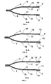
- FIGS. 7 to 9 schematically represent a sectional view along the axis AA of a respiratory protection mask according to different embodiments of the protective strip.
- lower edge and upper edge in relation to the elements define, respectively the nearest edge and the farthest edge of the face, when the mask is worn.
- the invention proposes a respiratory protection mask, in particular for single use.
- the mask is designed to retain solid or liquid particles suspended in the air and in particular viruses or bacteria likely to cause diseases such as influenza.
- the respiratory protection mask 1 comprises a porous protection piece 2 by filtration and a fastening element 3 secured to said piece so as to maintain said piece in front of at least the nose and the mouth of a wearer.
- the protective part is formed in particular of two elements 4,5, respectively upper and lower, which are associated with each other so as to be applied respectively facing the nose and the chin of the wearer.
- the figure 3 illustrates the upper elements 4 and lower 5 and the attachment element 3 before being secured.
- the combination of elements is made for example by welding such as ultrasonic welding, high frequency laser or heat, sewing, gluing or folding.
- the lower and upper elements are of trapezoidal shape, three sides of each trapezium being associated two by two to form the protective part, the large base of each trapezium being free to form the upper and lower edges of said room.
- Such a mask is called foldable type, that is to say that when it is not worn, the mask is substantially flat and is easily stackable.
- the two trapezoidal elements form a section whose periphery comes into contact with the wearer's face.
- the elements have the same dimensions so as to be perfectly superimposable.
- the elements are of different size and / or shape (s).
- the height of the trapezoidal lower member is greater than the height of the trapezoidal top member, so that the mask covers a larger portion of the chin.
- the protective piece is formed of three elements associated with each other, two elements being foldable on a central element.
- Such a type of mask is described in EP-A-814871 .
- the porous part 2 is provided with discrete outer zones 6, 7 on which the fastening element 3 is secured.
- the discrete outer zones 6, 7 are placed at the lateral ends of the lower edge 9 of the protective part 2.
- the mask comprises a protective strip 10 which is provided along at least a portion of an edge 8, 9 of the protection part 2, the strip 10 being secured to the protection part 2 on the securing zones 6,7 of the fastening element 3, said fastening element 3 being, in these areas, interposed between the protection part 2 and the protective strip 10 so that the strip 10 covers the fastening element 3.
- the protective strip 10 When the protective mask 1 is not worn, the protective strip 10 at least partially covers the fastening element 3 so as to protect it.
- the protective strip 10 in particular formed of an additional element, is associated continuously along the protective part 2 near an edge 8 of said piece.
- the protective strip is movable between a folded position along said edge 8 and an extended position allowing access to the fastening element 3.
- the association of the protective strip 10 with the protective part 2 is carried out for example by welding such as ultrasonic welding, high frequency, laser or heat, sewing, gluing or folding.
- the length of the protective strip 10 and / or the length of the fastening element is substantially equal to that of an edge 8, 9 of the protective part.
- the strip 10 completely covers the fastening element 3, keeping it along the porous part 2.
- the mask further comprises a protective strip 10 which is provided along at least a portion of an edge 8 of the protection piece 2, said strip being movable between a folded position along said edge and an extended position where it extends beyond said edge so as to extend the protection piece, said attachment member 3 being positioned so as to allow the deployment of the protective strip 10 during the use of the fastening element 3.
- the protective strip 10 is contiguous to the lower edge 13 of the lower member 5 and is foldable.
- the protective strip 10 When the protective mask 1 is not worn, the protective strip 10 is in the folded position and at least partially covers the fastening element 3 so as to protect it.
- the wearer When the mask 1 is worn, the wearer is disposed the fastening element 3 on the back of his head, then driving the protective strip 10 in its deployed position.
- the protective strip 10 is pressed against the wearer's face, ensuring a close contact between the mask and the wearer's face.
- This variant makes it possible to reduce as much as possible the possibilities of leaks in the face and to improve the tightness at the level of the face.
- the respiratory protection mask is thus able to ensure a good seal on the face to avoid contamination of the wearer.
- the fastening element is easily gripped because of its positioning on the outside of the protective mask and the arrangement of the protective strip of said element.
- a malleable insert 11 is provided on the upper member 4 to fit around the nose of the wearer.
- the insert 11 is in the form of a deformable metal strip, for example an aluminum strip.
- the insert 11 is arranged, for example by gluing, directly on the protective part 2 facing the nose. Alternatively, the insert 11 is inserted into the mask between two layers constituting the protective part. It is then maintained for example by welding points.
- the insert 11 is placed on the protective strip 10 of the mask.
- the protective strip 10 is provided along the lower edge 12 of the upper member 4 of the protective piece, so, in the deployed position, to be arranged against the nose of the wearer.
- the protective strip 10 is provided along the lower edge 13 of the lower member 5 so, in the deployed position, to be disposed against the underside of the chin.
- the seal at the lower face is improved.
- the length of the protective strip 10 is substantially equal to that of the lower edge 13 of the lower element 5 or of the upper element 4.
- the width of the protective strip 10 is less than 30% of the distance between the upper 8 and lower 9 edges of the protective part 10.
- the width of the strip 10 is less than 20% of the distance between the upper and lower edges 13 of the lower element 5.
- the upper 4 and lower 5 elements are trapezoidal, suitable dimensions for each of the trapezoids are 250 mm for the large base, 77 mm for the small base, and 103 mm for the height.
- the width of the protective strip is 15 mm.
- the mask is designed to retain particles in the air.
- the choice of material constituting the protective part and its characteristics such as porosity, density or thickness, depends on the end use of the mask.
- the protective piece 2 is formed of at least one layer of fibrous polymer material.
- the protective piece 2 is formed of a stack of several layers of meltblown and / or spunbond nonwoven polymer material, such as a spunbond / meltblown / spunbond (SMS) laminate.
- the nonwoven is especially chemically treated or electrostatically charged in order to increase its particle attraction capacity.
- the protective part comprises the superposition of three layers: an outer layer 15 comprising a spunbond-type nonwoven polymer material, an intermediate layer 16 comprising a meltblown nonwoven polymer material, an inner layer 17 comprising a polymer material non-woven spunbond type.
- Examples of usable polymeric materials are polypropylene, polyester, or expanded polytetrafluoroethylene (PTFE).
- PTFE polytetrafluoroethylene
- the protective strip 10 is made of a material identical to that of the protective piece or in a different material.
- the Figures 7 and 8 represent two embodiments of the protective strip.
- the protective strip 10 is formed of a fold of at least one inner layer 17 of the protective part 2.
- the protective strip 10 is formed of an additional element which is secured to the protection piece.
- the protective strip 10 is associated continuously with the edge of the protective part 2.
- the protective strip 10 is associated continuously along the upper layer 15 near an edge 8 of said part 2.
- the strip is formed of an additional element associated for example by welding over the entire length of the upper element 4, about 15 mm from the lower edge 8 of the upper element 4.
- the protective strip 10 is provided on either side of an edge of the protective piece.
- the protective strip 10 is associated on the inner face of the protective part 2 and forms a fold on the outer face.
- the protective strip is contiguous with the lower edge 12 of the upper element 4 or the lower edge 13 of the lower element 5 of the protective part 2.
- the association of the protective strip 10 with the protective part 2 is carried out for example by welding such as ultrasonic welding, high frequency, laser or heat, sewing, gluing.
- the protective strip 10 is formed of an additional element
- the protective strip may be made of a material different from or identical to that or those of the protective part.
- the protective strip 10 is formed of at least one layer of fibrous polymer material, especially non-woven material, such as a spunbond.
- the realization of the spunbond protective strip provides a feeling of softness and comfort to the mask wearer.
- the protective strip is made of a material impermeable to liquids and / or gases, such as polyethylene.
- the fastening element 3 is substantially of the same length as the protective strip 10 so that the strip entirely covers the fastening element when it is in the folded position.
- the fastening element 3 is advantageously flexible and elastic to be arranged around the head of the wearer.
- the length of the fastening element 3 in the unstretched state substantially corresponds to the distance between the two securing zones 6, 7.
- the fastening element 3 comprises a cord whose two ends are secured respectively to an outer zone 6, 7 of the protective part and each of the extreme lateral parts of the protective strip is respectively secured to an area 6, 7.
- the cord As the cord is secured to the lateral ends of the protective strip 10, it automatically unfolds in the deployed position, when the mask is worn.
- the fastening element 3 comprises a second cord.
- the ends of the second cord are secured to an inner zone of the protective part 2.
- the second bead is provided between the upper element 4 and the lower element 5 of the protection part 2 and is secured at its ends, at each of the lateral ends of the lower edges 12, 13 of the elements 4,5.
- the cord is inside the mask when the mask is not worn.
- the fastening element 3 comprises a second cord whose two ends are secured respectively to an outer zone of the protective part 2, and each of the extreme lateral parts of a second protective strip 18 is respectively secured to a zone.
- the embodiments of the second protective strip 18 are equivalent to those described in relation to the first protective strip 10.
- the first protective strip 10 is provided along the upper element of the protection part 2 and is associated in proximity with the edge 8 of the protective part, and does not extend beyond the protective part 2 to do not disturb the eyes of the wearer.
- the second protective strip 10 is provided along the lower edge 9 of the protective part 2 so that the band in the deployed position covers the chin.
- the protective strips 10, 18 are respectively provided along the lower edges 9 and upper 8 of the protective part, so that each of the strips in the deployed position covers respectively the chin and the nose of the wearer.
- the protective strips 10, 18 extend the upper 4 and lower 5 elements of the protection part 2 so as to guarantee the absence of leakage over the entire periphery of the mask in contact with the wearer's face.
Landscapes
- Health & Medical Sciences (AREA)
- General Health & Medical Sciences (AREA)
- Physical Education & Sports Medicine (AREA)
- Engineering & Computer Science (AREA)
- Textile Engineering (AREA)
- Respiratory Apparatuses And Protective Means (AREA)
Claims (22)
- Atemschutzmaske (1) umfassend ein poröses Filter-Schutzstück (2) und ein Befestigungselement (3), das fest mit dem Stück verbunden und dazu bestimmt ist, am Hinterkopf eines Trägers angeordnet zu werden, sodass das besagte Stück zumindest vor der Nase und dem Mund des Trägers festgehalten wird, wobei das poröse Stück (2) mit diskreten äußeren Zonen (6, 7) versehen ist, auf denen das Befestigungselement (3) kraftschlüssig befestigt ist, und die besagte Maske darüber hinaus ein Schutzband (10) umfasst, das entlang zumindest eines Teils eines Randes (8, 9) des Schutzstückes vorgesehen ist, und das besagte Band (10) in den Verbindungsbereichen (6, 7) des Befestigungselements (3) kraftschlüssig mit dem Schutzstück (2) verbunden ist, und das besagte Befestigungselement (3) in diesen Bereichen zwischen dem Schutzstück (2) und dem Schutzband (10) eingesetzt ist, sodass das Band (10) das Befestigungselement (3) überdeckt, dadurch gekennzeichnet, dass das besagte Schutzband (10) zwischen einer entlang des besagten Randes (8, 9) gefalteten Position und einer entfalteten Position bewegt werden kann, die den Zugriff auf das Befestigungselement freigibt.
- Atemschutzmaske (1) nach Anspruch 1, dadurch gekennzeichnet, dass sich das Schutzband (10) in seiner entfalteten Position über den besagten Rand (8, 9) hinaus erstreckt, sodass das Schutzstück (2) verlängert wird, und das besagte Befestigungselement (3) so positioniert ist, dass es bei Verwendung des Befestigungselements (3) die Entfaltung des Schutzbandes (10) ermöglicht.
- Atemschutzmaske (1) nach Anspruch 1, dadurch gekennzeichnet, dass das Schutzband (10) durchgehend entlang des Schutzstückes (2) in der Nähe eines Randes (8, 9) des besagten Stückes angeordnet ist.
- Atemschutzmaske (1) nach irgendeinem der Ansprüche 1 bis 3, dadurch gekennzeichnet, dass die Länge des Schutzbandes (10) genau jener eines Randes (8, 9) entspricht.
- Atemschutzmaske (1) nach irgendeinem der Ansprüche 1 bis 4, dadurch gekennzeichnet, dass die Länge des Befestigungselements (3) genau jener eines Randes (8, 9) entspricht.
- Atemschutzmaske (1) nach irgendeinem der Ansprüche 1 bis 5, dadurch gekennzeichnet, dass das Schutzstück (2) aus zwei Elementen, nämlich einem oberen (4) und einem unteren (5) gebildet wird, die so miteinander verbunden sind, dass sie jeweils gegenüber der Nase und dem Kinn des Trägers angelegt werden können.
- Atemschutzmaske (1) nach Anspruch 6, dadurch gekennzeichnet, dass am oberen Element (4) ein verformbarer Einsatz (11) zum Anlegen um die Nase des Trägers vorgesehen ist.
- Atemschutzmaske (1) nach Anspruch 6 oder 7, dadurch gekennzeichnet, dass das Schutzband (10) entlang des unteren Randes (13) des unteren Elements (5) vorgesehen ist, sodass es in der entfalteten Position gegen die Unterseite des Kinns angelegt werden kann.
- Atemschutzmaske (1) nach irgendeinem der Ansprüche 6 bis 8, dadurch gekennzeichnet, dass die Elemente (4, 5) eine trapezartige Form aufweisen, wobei drei Seiten jedes Trapezes jeweils paarweise zugeordnet sind, um das Schutzstück (2) zu bilden, und die große Basis jedes Trapezes frei ist, um den oberen (12) und unteren (13) Rand des besagten Stückes zu bilden.
- Atemschutzmaske (1) nach irgendeinem der Ansprüche 1 bis 9, dadurch gekennzeichnet, dass die Breite des Schutzbandes (10) um 30% kleiner ist, als der Abstand zwischen dem oberen (8) und dem unteren (9) Rand des Schutzstückes (2).
- Atemschutzmaske (1) nach irgendeinem der Ansprüche 1 bis 10, dadurch gekennzeichnet, dass das Schutzstück (2) aus zumindest einer Schicht eines faserigen Polymerwerkstoffes gebildet wird.
- Atemschutzmaske (1) nach Anspruch 11, dadurch gekennzeichnet, dass das Schutzstück (2) die Überlagerung von drei Schichten umfasst: eine Außenschicht (15) umfassend ein Polymer-Vlies des Typs Spunbond, eine Zwischenschicht (16) umfassend ein Polymer-Vlies des Typs Meltblown, eine Innenschicht (17) umfassend ein Polymer-Vlies des Typs Spunbond.
- Atemschutzmaske (1) nach Anspruch 11 oder 12, dadurch gekennzeichnet, dass das Schutzband (10) aus einer Falte zumindest einer Innenschicht (17) des Schutzstücks (2) gebildet wird.
- Atemschutzmaske (1) nach irgendeinem der Ansprüche 1 bis 12, dadurch gekennzeichnet, dass das Schutzband (10) aus einem zusätzlichen Element gebildet wird, das fest mit dem Schutzstück (2) verbunden ist.
- Atemschutzmaske (1) nach Anspruch 14, dadurch gekennzeichnet, dass das Schutzband (10) beiderseits eines Randes (8, 9) des Schutzstückes (2) vorgesehen ist.
- Atemschutzmaske (1) nach Anspruch 14, dadurch gekennzeichnet, dass das Schutzband (10) durchgehend am Rand des besagten Schutzstückes (2) befestigt ist.
- Atemschutzmaske (1) nach irgendeinem der Ansprüche 14 bis 16, dadurch gekennzeichnet, dass das Schutzband (10) aus zumindest einer Schicht eines faserigen Polymerwerkstoffes gebildet wird.
- Atemschutzmaske (1) nach irgendeinem der Ansprüche 1 bis 17, dadurch gekennzeichnet, dass das Befestigungselement (3) eine Schnur umfasst, deren beiden Enden jeweils in einem äußeren Bereich (6, 7) fest mit dem Schutzstück verbunden sind, wobei jeder der äußeren Seitenabschnitte des Schutzbandes (10) jeweils fest mit einem der besagten äußeren Bereiche (6, 7) verbunden ist.
- Atemschutzmaske (1) nach Anspruch 18, dadurch gekennzeichnet, dass das Befestigungselement (3) eine zweite Schnur umfasst, deren beiden Enden fest mit einem unteren Bereich des Schutzstückes (2) verbunden sind.
- Atemschutzmaske (1) nach Anspruch 18, dadurch gekennzeichnet, dass das Befestigungselement (3) eine zweite Schnur umfasst, deren beiden Enden jeweils fest mit einem äußeren Bereich des Schutzstückes (2) verbunden sind, und die besagte Maske ein zweites Schutzband (18) umfasst, dessen seitliche äußere Enden jeweils fest mit dem besagten äußeren Bereich verbunden sind.
- Atemschutzmaske (1) nach Anspruch 20, dadurch gekennzeichnet, dass die Schutzbänder (10, 18) jeweils entlang des unteren (8) und oberen (9) Randes des Schutzstückes vorgesehen sind.
- Atemschutzmaske (1) nach irgendeinem der Ansprüche 1 bis 21, dadurch gekennzeichnet, dass das Befestigungselement (3) biegsam und elastisch ist, um um den Kopf des Trägers angeordnet werden zu können.
Applications Claiming Priority (1)
| Application Number | Priority Date | Filing Date | Title |
|---|---|---|---|
| FR0552188A FR2888471B1 (fr) | 2005-07-13 | 2005-07-13 | Masque de protection respiratoire comprenant une bande protectrice |
Publications (4)
| Publication Number | Publication Date |
|---|---|
| EP1743535A2 EP1743535A2 (de) | 2007-01-17 |
| EP1743535A3 EP1743535A3 (de) | 2008-06-11 |
| EP1743535B1 true EP1743535B1 (de) | 2011-12-21 |
| EP1743535B9 EP1743535B9 (de) | 2012-04-11 |
Family
ID=36090750
Family Applications (1)
| Application Number | Title | Priority Date | Filing Date |
|---|---|---|---|
| EP06291082A Active EP1743535B9 (de) | 2005-07-13 | 2006-06-30 | Beatmungsmaske mit Schutzstreifen |
Country Status (4)
| Country | Link |
|---|---|
| EP (1) | EP1743535B9 (de) |
| AT (1) | ATE537715T1 (de) |
| ES (1) | ES2379279T3 (de) |
| FR (1) | FR2888471B1 (de) |
Families Citing this family (8)
| Publication number | Priority date | Publication date | Assignee | Title |
|---|---|---|---|---|
| CN103156309A (zh) * | 2013-03-28 | 2013-06-19 | 江西3L医用制品集团股份有限公司 | 一种鸭嘴形口罩 |
| US20150101617A1 (en) * | 2013-10-14 | 2015-04-16 | 3M Innovative Properties Company | Filtering Face-Piece Respirator With Increased Friction Perimeter |
| US9868002B2 (en) | 2014-07-17 | 2018-01-16 | 3M Innovative Properties Company | Respirator including contrast layer |
| DE102020113264A1 (de) * | 2020-05-15 | 2021-11-18 | Paul Hartmann Ag | Atemschutzmaske für den einmaligen Gebrauch zur Bedeckung von Mund und Nase und Verfahren zu ihrer Herstellung |
| US12458740B2 (en) | 2022-03-10 | 2025-11-04 | Terumo Bct, Inc. | Modular serviceability sleds and interconnections |
| US12521474B2 (en) | 2022-03-10 | 2026-01-13 | Terumo Bct, Inc. | Soft cassette with integrated features |
| US12379916B2 (en) | 2022-03-10 | 2025-08-05 | Terumo Bct, Inc. | Communications and operation control of apheresis systems |
| US12478551B2 (en) | 2022-03-10 | 2025-11-25 | Terumo Bct, Inc. | Collection bottle with integrated cap, handle, and shield features |
Citations (1)
| Publication number | Priority date | Publication date | Assignee | Title |
|---|---|---|---|---|
| WO2001089330A2 (en) * | 2000-05-24 | 2001-11-29 | Cabot Safety Intermediate Corporation | Disposable respirator |
Family Cites Families (4)
| Publication number | Priority date | Publication date | Assignee | Title |
|---|---|---|---|---|
| FR2467608A1 (fr) * | 1979-10-19 | 1981-04-30 | Mutexil Soc | Masque respiratoire facial |
| US5561863A (en) * | 1994-10-04 | 1996-10-08 | Kimberly-Clark Corporation | Surgical face mask |
| US6173712B1 (en) * | 1998-04-29 | 2001-01-16 | Kimberly-Clark Worldwide, Inc. | Disposable aerosol mask with disparate portions |
| JP3295413B2 (ja) * | 2000-01-21 | 2002-06-24 | サンエム・パッケージ株式会社 | マスク |
-
2005
- 2005-07-13 FR FR0552188A patent/FR2888471B1/fr not_active Expired - Lifetime
-
2006
- 2006-06-30 ES ES06291082T patent/ES2379279T3/es active Active
- 2006-06-30 AT AT06291082T patent/ATE537715T1/de active
- 2006-06-30 EP EP06291082A patent/EP1743535B9/de active Active
Patent Citations (1)
| Publication number | Priority date | Publication date | Assignee | Title |
|---|---|---|---|---|
| WO2001089330A2 (en) * | 2000-05-24 | 2001-11-29 | Cabot Safety Intermediate Corporation | Disposable respirator |
Also Published As
| Publication number | Publication date |
|---|---|
| FR2888471B1 (fr) | 2007-09-07 |
| EP1743535A3 (de) | 2008-06-11 |
| EP1743535B9 (de) | 2012-04-11 |
| ATE537715T1 (de) | 2012-01-15 |
| FR2888471A1 (fr) | 2007-01-19 |
| EP1743535A2 (de) | 2007-01-17 |
| ES2379279T3 (es) | 2012-04-24 |
Similar Documents
| Publication | Publication Date | Title |
|---|---|---|
| FR2511253A1 (fr) | Masque respiratoire pliant pour la securite du travail et son procede de fabrication | |
| EP2934267B1 (de) | Sauger-falltür eines staubsaugers | |
| EP1743535B9 (de) | Beatmungsmaske mit Schutzstreifen | |
| FR2523434A1 (fr) | Accessoire d'ostomie et fixation a plastron pour cet accessoire | |
| FR2485931A1 (fr) | Masque respiratoire perfectionne du type filtrant a extremite en creux | |
| LU85429A1 (fr) | Protection contre l'incontinence masculine | |
| FR2564312A1 (fr) | Dispositif d'accouplement a bagues pour appareil d'ostomie | |
| EP0990429A1 (de) | In einem Ostomiebeutel integriertes Filter- und Entlüftungssystem | |
| EP0729733B1 (de) | Aufblasbarer Beutel, insbesondere für künstlichen After | |
| FR2629986A1 (fr) | Casque de protection polyvalent | |
| WO2016142601A1 (fr) | Dispositif de repos | |
| EP1757196A2 (de) | Gesichtsmaske mit Sicherheitssiegel | |
| EP0771229A1 (de) | Faltbare hintergrundstruktur | |
| FR3111565A1 (fr) | Masque de protection respiratoire à paroi d’interface transparente et armature intégrant une ou plusieurs cartouche(s) amovible(s) de matériau filtrant | |
| FR3053256A1 (fr) | Masque anti-polution | |
| FR3067613B1 (fr) | Masque antipollution | |
| FR3129064A1 (fr) | Masque de protection respiratoire anti-écrasement | |
| EP0260182A2 (de) | Verfahren zur Herstellung eines Sesselschoners und Sesselschoner | |
| FR3111260A3 (fr) | Masque | |
| FR3111633A1 (fr) | Pastille de céramique filtrante pour masque de protection respiratoire. | |
| BE883356A (fr) | Perfectionnements aux respirateurs | |
| EP3061431B1 (de) | Sportbrillen | |
| FR2908050A1 (fr) | Masque respiratoire | |
| FR2467608A1 (fr) | Masque respiratoire facial | |
| FR2924907A1 (fr) | Article destine a appliquer et/ou a enlever des produits cosmetiques sur la peau, notamment sur le visage, et de preference autour des yeux |
Legal Events
| Date | Code | Title | Description |
|---|---|---|---|
| PUAI | Public reference made under article 153(3) epc to a published international application that has entered the european phase |
Free format text: ORIGINAL CODE: 0009012 |
|
| AK | Designated contracting states |
Kind code of ref document: A2 Designated state(s): AT BE BG CH CY CZ DE DK EE ES FI FR GB GR HU IE IS IT LI LT LU LV MC NL PL PT RO SE SI SK TR |
|
| AX | Request for extension of the european patent |
Extension state: AL BA HR MK YU |
|
| PUAL | Search report despatched |
Free format text: ORIGINAL CODE: 0009013 |
|
| AK | Designated contracting states |
Kind code of ref document: A3 Designated state(s): AT BE BG CH CY CZ DE DK EE ES FI FR GB GR HU IE IS IT LI LT LU LV MC NL PL PT RO SE SI SK TR |
|
| AX | Request for extension of the european patent |
Extension state: AL BA HR MK RS |
|
| 17P | Request for examination filed |
Effective date: 20081016 |
|
| 17Q | First examination report despatched |
Effective date: 20081127 |
|
| AKX | Designation fees paid |
Designated state(s): AT BE BG CH CY CZ DE DK EE ES FI FR GB GR HU IE IS IT LI LT LU LV MC NL PL PT RO SE SI SK TR |
|
| GRAP | Despatch of communication of intention to grant a patent |
Free format text: ORIGINAL CODE: EPIDOSNIGR1 |
|
| GRAS | Grant fee paid |
Free format text: ORIGINAL CODE: EPIDOSNIGR3 |
|
| GRAA | (expected) grant |
Free format text: ORIGINAL CODE: 0009210 |
|
| AK | Designated contracting states |
Kind code of ref document: B1 Designated state(s): AT BE BG CH CY CZ DE DK EE ES FI FR GB GR HU IE IS IT LI LT LU LV MC NL PL PT RO SE SI SK TR |
|
| REG | Reference to a national code |
Ref country code: GB Ref legal event code: FG4D Free format text: NOT ENGLISH |
|
| REG | Reference to a national code |
Ref country code: CH Ref legal event code: EP |
|
| REG | Reference to a national code |
Ref country code: AT Ref legal event code: REF Ref document number: 537715 Country of ref document: AT Kind code of ref document: T Effective date: 20120115 |
|
| REG | Reference to a national code |
Ref country code: IE Ref legal event code: FG4D |
|
| REG | Reference to a national code |
Ref country code: DE Ref legal event code: R096 Ref document number: 602006026492 Country of ref document: DE Effective date: 20120223 |
|
| REG | Reference to a national code |
Ref country code: NL Ref legal event code: VDEP Effective date: 20111221 |
|
| REG | Reference to a national code |
Ref country code: ES Ref legal event code: FG2A Ref document number: 2379279 Country of ref document: ES Kind code of ref document: T3 Effective date: 20120424 |
|
| PG25 | Lapsed in a contracting state [announced via postgrant information from national office to epo] |
Ref country code: LT Free format text: LAPSE BECAUSE OF FAILURE TO SUBMIT A TRANSLATION OF THE DESCRIPTION OR TO PAY THE FEE WITHIN THE PRESCRIBED TIME-LIMIT Effective date: 20111221 |
|
| LTIE | Lt: invalidation of european patent or patent extension |
Effective date: 20111221 |
|
| PG25 | Lapsed in a contracting state [announced via postgrant information from national office to epo] |
Ref country code: LV Free format text: LAPSE BECAUSE OF FAILURE TO SUBMIT A TRANSLATION OF THE DESCRIPTION OR TO PAY THE FEE WITHIN THE PRESCRIBED TIME-LIMIT Effective date: 20111221 Ref country code: GR Free format text: LAPSE BECAUSE OF FAILURE TO SUBMIT A TRANSLATION OF THE DESCRIPTION OR TO PAY THE FEE WITHIN THE PRESCRIBED TIME-LIMIT Effective date: 20120322 Ref country code: SI Free format text: LAPSE BECAUSE OF FAILURE TO SUBMIT A TRANSLATION OF THE DESCRIPTION OR TO PAY THE FEE WITHIN THE PRESCRIBED TIME-LIMIT Effective date: 20111221 Ref country code: SE Free format text: LAPSE BECAUSE OF FAILURE TO SUBMIT A TRANSLATION OF THE DESCRIPTION OR TO PAY THE FEE WITHIN THE PRESCRIBED TIME-LIMIT Effective date: 20111221 Ref country code: NL Free format text: LAPSE BECAUSE OF FAILURE TO SUBMIT A TRANSLATION OF THE DESCRIPTION OR TO PAY THE FEE WITHIN THE PRESCRIBED TIME-LIMIT Effective date: 20111221 |
|
| PG25 | Lapsed in a contracting state [announced via postgrant information from national office to epo] |
Ref country code: CY Free format text: LAPSE BECAUSE OF FAILURE TO SUBMIT A TRANSLATION OF THE DESCRIPTION OR TO PAY THE FEE WITHIN THE PRESCRIBED TIME-LIMIT Effective date: 20111221 |
|
| REG | Reference to a national code |
Ref country code: IE Ref legal event code: FD4D |
|
| PG25 | Lapsed in a contracting state [announced via postgrant information from national office to epo] |
Ref country code: EE Free format text: LAPSE BECAUSE OF FAILURE TO SUBMIT A TRANSLATION OF THE DESCRIPTION OR TO PAY THE FEE WITHIN THE PRESCRIBED TIME-LIMIT Effective date: 20111221 Ref country code: SK Free format text: LAPSE BECAUSE OF FAILURE TO SUBMIT A TRANSLATION OF THE DESCRIPTION OR TO PAY THE FEE WITHIN THE PRESCRIBED TIME-LIMIT Effective date: 20111221 Ref country code: BG Free format text: LAPSE BECAUSE OF FAILURE TO SUBMIT A TRANSLATION OF THE DESCRIPTION OR TO PAY THE FEE WITHIN THE PRESCRIBED TIME-LIMIT Effective date: 20120321 Ref country code: CZ Free format text: LAPSE BECAUSE OF FAILURE TO SUBMIT A TRANSLATION OF THE DESCRIPTION OR TO PAY THE FEE WITHIN THE PRESCRIBED TIME-LIMIT Effective date: 20111221 Ref country code: IE Free format text: LAPSE BECAUSE OF FAILURE TO SUBMIT A TRANSLATION OF THE DESCRIPTION OR TO PAY THE FEE WITHIN THE PRESCRIBED TIME-LIMIT Effective date: 20111221 Ref country code: IS Free format text: LAPSE BECAUSE OF FAILURE TO SUBMIT A TRANSLATION OF THE DESCRIPTION OR TO PAY THE FEE WITHIN THE PRESCRIBED TIME-LIMIT Effective date: 20120421 |
|
| PG25 | Lapsed in a contracting state [announced via postgrant information from national office to epo] |
Ref country code: RO Free format text: LAPSE BECAUSE OF FAILURE TO SUBMIT A TRANSLATION OF THE DESCRIPTION OR TO PAY THE FEE WITHIN THE PRESCRIBED TIME-LIMIT Effective date: 20111221 Ref country code: PT Free format text: LAPSE BECAUSE OF FAILURE TO SUBMIT A TRANSLATION OF THE DESCRIPTION OR TO PAY THE FEE WITHIN THE PRESCRIBED TIME-LIMIT Effective date: 20120423 Ref country code: PL Free format text: LAPSE BECAUSE OF FAILURE TO SUBMIT A TRANSLATION OF THE DESCRIPTION OR TO PAY THE FEE WITHIN THE PRESCRIBED TIME-LIMIT Effective date: 20111221 |
|
| PLBE | No opposition filed within time limit |
Free format text: ORIGINAL CODE: 0009261 |
|
| STAA | Information on the status of an ep patent application or granted ep patent |
Free format text: STATUS: NO OPPOSITION FILED WITHIN TIME LIMIT |
|
| PG25 | Lapsed in a contracting state [announced via postgrant information from national office to epo] |
Ref country code: DK Free format text: LAPSE BECAUSE OF FAILURE TO SUBMIT A TRANSLATION OF THE DESCRIPTION OR TO PAY THE FEE WITHIN THE PRESCRIBED TIME-LIMIT Effective date: 20111221 |
|
| REG | Reference to a national code |
Ref country code: AT Ref legal event code: MK05 Ref document number: 537715 Country of ref document: AT Kind code of ref document: T Effective date: 20111221 |
|
| 26N | No opposition filed |
Effective date: 20120924 |
|
| REG | Reference to a national code |
Ref country code: DE Ref legal event code: R097 Ref document number: 602006026492 Country of ref document: DE Effective date: 20120924 |
|
| PG25 | Lapsed in a contracting state [announced via postgrant information from national office to epo] |
Ref country code: AT Free format text: LAPSE BECAUSE OF FAILURE TO SUBMIT A TRANSLATION OF THE DESCRIPTION OR TO PAY THE FEE WITHIN THE PRESCRIBED TIME-LIMIT Effective date: 20111221 Ref country code: MC Free format text: LAPSE BECAUSE OF NON-PAYMENT OF DUE FEES Effective date: 20120630 |
|
| REG | Reference to a national code |
Ref country code: CH Ref legal event code: PL |
|
| REG | Reference to a national code |
Ref country code: CH Ref legal event code: PL |
|
| PG25 | Lapsed in a contracting state [announced via postgrant information from national office to epo] |
Ref country code: CH Free format text: LAPSE BECAUSE OF NON-PAYMENT OF DUE FEES Effective date: 20120630 Ref country code: LI Free format text: LAPSE BECAUSE OF NON-PAYMENT OF DUE FEES Effective date: 20120630 |
|
| PG25 | Lapsed in a contracting state [announced via postgrant information from national office to epo] |
Ref country code: FI Free format text: LAPSE BECAUSE OF FAILURE TO SUBMIT A TRANSLATION OF THE DESCRIPTION OR TO PAY THE FEE WITHIN THE PRESCRIBED TIME-LIMIT Effective date: 20111221 |
|
| PG25 | Lapsed in a contracting state [announced via postgrant information from national office to epo] |
Ref country code: TR Free format text: LAPSE BECAUSE OF FAILURE TO SUBMIT A TRANSLATION OF THE DESCRIPTION OR TO PAY THE FEE WITHIN THE PRESCRIBED TIME-LIMIT Effective date: 20111221 |
|
| PG25 | Lapsed in a contracting state [announced via postgrant information from national office to epo] |
Ref country code: LU Free format text: LAPSE BECAUSE OF NON-PAYMENT OF DUE FEES Effective date: 20120630 |
|
| PG25 | Lapsed in a contracting state [announced via postgrant information from national office to epo] |
Ref country code: HU Free format text: LAPSE BECAUSE OF FAILURE TO SUBMIT A TRANSLATION OF THE DESCRIPTION OR TO PAY THE FEE WITHIN THE PRESCRIBED TIME-LIMIT Effective date: 20060630 |
|
| REG | Reference to a national code |
Ref country code: FR Ref legal event code: PLFP Year of fee payment: 11 |
|
| REG | Reference to a national code |
Ref country code: FR Ref legal event code: PLFP Year of fee payment: 12 |
|
| REG | Reference to a national code |
Ref country code: FR Ref legal event code: PLFP Year of fee payment: 13 |
|
| PGFP | Annual fee paid to national office [announced via postgrant information from national office to epo] |
Ref country code: GB Payment date: 20240627 Year of fee payment: 19 |
|
| PGFP | Annual fee paid to national office [announced via postgrant information from national office to epo] |
Ref country code: DE Payment date: 20240627 Year of fee payment: 19 |
|
| PGFP | Annual fee paid to national office [announced via postgrant information from national office to epo] |
Ref country code: FR Payment date: 20240625 Year of fee payment: 19 |
|
| PGFP | Annual fee paid to national office [announced via postgrant information from national office to epo] |
Ref country code: BE Payment date: 20240627 Year of fee payment: 19 |
|
| PGFP | Annual fee paid to national office [announced via postgrant information from national office to epo] |
Ref country code: IT Payment date: 20240619 Year of fee payment: 19 |
|
| PGFP | Annual fee paid to national office [announced via postgrant information from national office to epo] |
Ref country code: ES Payment date: 20240701 Year of fee payment: 19 |