EP1742548B1 - Vorrichtung zur umwandlung eines strassenschuhs bei bedarf in einen sportschuh und an diese vorrichtung adaptierte schuhe - Google Patents
Vorrichtung zur umwandlung eines strassenschuhs bei bedarf in einen sportschuh und an diese vorrichtung adaptierte schuhe Download PDFInfo
- Publication number
- EP1742548B1 EP1742548B1 EP05769215A EP05769215A EP1742548B1 EP 1742548 B1 EP1742548 B1 EP 1742548B1 EP 05769215 A EP05769215 A EP 05769215A EP 05769215 A EP05769215 A EP 05769215A EP 1742548 B1 EP1742548 B1 EP 1742548B1
- Authority
- EP
- European Patent Office
- Prior art keywords
- shoe
- sole
- strip
- winglets
- winglet
- Prior art date
- Legal status (The legal status is an assumption and is not a legal conclusion. Google has not performed a legal analysis and makes no representation as to the accuracy of the status listed.)
- Expired - Lifetime
Links
Images


Classifications
-
- A—HUMAN NECESSITIES
- A43—FOOTWEAR
- A43C—FASTENINGS OR ATTACHMENTS OF FOOTWEAR; LACES IN GENERAL
- A43C15/00—Non-skid devices or attachments
- A43C15/02—Non-skid devices or attachments attached to the sole
-
- A—HUMAN NECESSITIES
- A43—FOOTWEAR
- A43C—FASTENINGS OR ATTACHMENTS OF FOOTWEAR; LACES IN GENERAL
- A43C15/00—Non-skid devices or attachments
- A43C15/06—Ice-gripping devices or attachments, e.g. ice-spurs, ice-cleats, ice-creepers, crampons; Climbing devices or attachments, e.g. mountain climbing irons
- A43C15/061—Ice-gripping devices or attachments, e.g. ice-cleats, ice-creepers
- A43C15/063—Ice-gripping devices or attachments, e.g. ice-cleats, ice-creepers with ice-gripping means projecting from the front foot region
Definitions
- the invention relates to a device for transforming on demand a city shoe into a sports shoe and shoes equipped with this device.
- the shoe is convertible to be adaptable to the practice of a sport, for example golf or walking in rough terrain, and to also allow to walk normally on an ordinary surface such as a solid ground, a floor or floor covering, for example to move in a gym or cloakroom or reception hall before or after the practice of the sport.
- the publication US 1,552,512 describes a device consisting of a single plate to be applied under the heel and which has a front wing and a rear wing which rise and bear respectively against the front edge and the rear edge of the heel.
- the publication DE 867 968 describes a device consisting of a single U-shaped plate which is applied in the area of the midsole between the sole and the heel and whose wings are provided with passages for retaining straps.
- the publication US 3,713,233 discloses a device consisting of a single elastic flexible plate adjoining an extension to the underside of the heel of the shoe, the plate being adapted to occupy a service position in which the plate is located under the extension, in the through of the shoe, or a retracted position in which the plate is located behind the shoe with the pins hidden between the shoe and the pad.
- the extension is secured, by gluing or by manufacture, the sole of the heel and the plate is provided with wings adapted to be folded against the sides of the shoe and be fixed to these sides by passing hollow buttons. in holes of the wings and screwed on screws passing in perforations of the sides of the shoe.
- the pads are embedded in recesses formed in the underside of the sole to prevent movement of the pads during walking.
- the present invention particularly relates to a device easy to set up and remove, effective, which contributes to give the shoe a satisfactory appearance, without the disadvantages of known devices.
- a device consisting of two plates (2, 3; 20, 30) designed to be arranged respectively under the forefoot and under the heel, each plate being at a distance from the corresponding end.
- the sole having two longitudinal edges (2a, 2b, 20a, 20b, 3a, 3b, 30a, 30b) which extend through the sole and two side edges (2c, 2d, 3c, 3d, 20c, 20d; 30c, 30d) provided with side wings (8, 9; 80,90) which back up against the vertical sides of the sole, these fins and the vertical sides of the sole having cooperating means for the detachable attachment of the plate to the shoe, characterized in that the plates (2, 3; 20, 30) are applied protruding on the underside of the shoe, in that the two side edges of the same plate are not parallel and have different widths, and in that the fin (9; 90) adjoining the lateral edge of the shoe; greater width is up against the side of the shoe which will be turned outwards and is provided with two
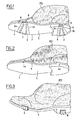
- the right foot town shoe (PD) shown on the Figures 1 to 3 is provided with two nose pads (2,3), respectively under the forefoot (4) and under the heel (5), projecting on the underside of the sole S (see figure 12 ), away from the ends of the sole.
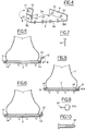
- the plate (2) located under the forefoot ( fig.4 ) has two rectilinear longitudinal edges (2a, 2b) which form an acute angle between them.
- these two edges are between them an angle of 20 ° to 40 °.
- the plate has two side edges (2c, 2d) which are provided with respective fins (8, 9) which are adjacent to these edges and which rise on the sides (6, 7) of the sole.
- the two side edges (8, 9) have unequal widths and are not parallel.
- the plate has the form of an irregular quadrilateral whose opposite sides are neither parallel nor of the same length ( figure 12 ). This shape contributes to maintaining the plate in place despite possible frontal impacts.
- the small fin (8) located against the left side of the right foot shoe (6) is provided with a hole (10) to allow a rod (11) carried by an extension (12) attached to the fin by a hinge (13) to pass through this hole when the extension is folded over the fin ( Figures 4 to 6 ).
- This rod (11) is intended to fit into an anchor (14) inserted obliquely in the left side (6) of the sole.
- the stem is full or hollow.
- the small fin (8) directly carries the rod (11) which is then provided with a head (11b) which allows to extract it by means of the hand or a tool.
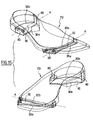
- the large fin (9) carries two fixed studs (15,16) intended to fit into corresponding hollow pins (17,18) inserted into holes in the right side (7) of the sole ( fig.11 ).
- the small fin (8) is perpendicular to the wafer while the large fin (9) is perpendicular or inclined outwards with respect to the wafer ( figures 3 and 4 ).
- the sides of the soleplate against which the fins of the wafer are provided have flats or notches which ensure good contact of the fins with these sides.
- On the figure 12 M is the plane of the flats (6a, 7a) for the fins (8,9) of the plate (2) applied under the forefoot of the left foot shoe.
- the pads are designed so that the small fins are turned inward, that is to say towards the interval between the shoes, so that the user can easily start the removal of a plate by placing the corresponding foot on the other knee and then apprehending the small wing to extract the sole of the fixing rod that carries the extension or, if the wing gate a removable rod, by acting on the head of this rod to extract the rod of the sole to detach the fin from the sole, after which it can lift the plate and extract the sole pins that fixed the large fin.
- the figure 11 is an enlarged view of a sole at the location of a ventilation hole (20) of the shoe which slants through the sole (S) and has received a hollow peg (17) adapted to receive a hollow rod ( 15) for fixing the fin (9) of the wafer.
- This rod has been represented only by its head (15a) visible outside the fin.
- the wafer and the fins are preferably thin metal with a thickness of at most a few millimeters. It is provided with pins, streaks, etc., depending on the sport that will be practiced. The user can thus have a set of pads for the practice of different sports or to adapt to a variety of terrains.
- the longitudinal edges of the plates are rectilinear. Alternatively, these edges may be curvilinear. In fact, the edges have any desired profile to facilitate the maintaining the wafer and its resistance to frontal impacts.
- the mean axes of the curves make an acute angle between them, preferably in the range 20 ° to 40 °.
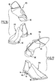
- the large fin (90) carries two pins (140) capable of being embedded in recesses in relation formed on the side of the sole which will be turned outward (and therefore seen during walking) .
- the small fin (80) carries an upper claw (141) adapted to engage from above on the sole.
- the wafer for example nylon or other synthetic material having the desired qualities of abrasion resistance and a certain flexibility, came from molding with its nipples and claw.
- the nipples are advantageously provided with a gripping tab (not shown) which enters with them in the holes of the sole but which can be grasped to extract the stud from the hole of the sole, similarly to the connecting blocks used in the computer connection.
- notches are formed on the sides of the shoe for receiving the claws (142).
- the user proceeds as indicated above for the previous embodiment, except that after having threaded the nipples of a plate in the housing provided for this purpose in the sole on one side of the shoe , it pulls on the plate taking advantage of the flexibility of the plate or the sole, until hanging the claw on the sole, on the other side of the shoe ( figures 14 and 15 ).
- the figure 15 shows two views of a low shoe for right foot (PD) equipped with a device according to the invention.
- PD low shoe for right foot
- the nipples are located on the fins on the right side of the shoe facing outward while the claws are visible on the left side.
- the longitudinal edges (20a, 20b) of the plate (20) located under the forefoot are not parallel to each other and make an acute angle between them. These edges are also oblique with respect to the transverse axis A of the sole ( figure 15 ). In fact, these edges have a curvilinear shape which reduces the incidence on the plate of frontal shocks that tend to move it.
- the invention is not limited to these exemplary embodiments.
Landscapes
- Footwear And Its Accessory, Manufacturing Method And Apparatuses (AREA)
Claims (24)
- Straßenschuh, mit einer abnehmbaren Vorrichtung ausgestattet, um den Straßenschuh bei Bedarf in einen Sportschuh umzuwandeln, wobei diese Vorrichtung von zwei Platten (2, 3; 20, 30) gebildet wird, die ausgebildet sind, um jeweils unter dem Vorderfuß und unter der Ferse angeordnet zu werden, wobei sich jede Platte in Entfernung vom entsprechenden Ende der Sohle befindet, zwei Längsränder (2a, 2b; 20a, 20b; 3a, 3b; 30a, 30b) aufweisend, die sich quer zur Sohle erstrecken, und zwei Seitenränder (2c, 2d; 3c, 3d; 20c, 20d; 30c, 30d), die mit seitlichen Flügeln (8, 9; 80, 90) versehen sind, die an den vertikalen Seiten der Sohle ansteigen, wobei diese Flügel und die vertikalen Seiten der Sohle Mittel aufweisen, die zur lösbaren Befestigung der Platte am Schuh zusammenarbeiten, dadurch gekennzeichnet, dass die Platten (2, 3; 20, 30) hervorragend auf der Unterseite des Schuhs angebracht sind, dass die zwei Seitenränder derselben Platte nicht parallel sind und unterschiedliche Breiten haben, und dass der am breiteren Seitenrand anliegende Flügel (9; 90) an der Seite des Schuhs aufsteigt, der nach außen gekehrt ist und mit zwei Zapfen (14; 140) versehen ist, die in entsprechende Öffnungen der Sohle einzupassen sind, währenddessen der am schmaleren Seitenrand anliegende Flügel (8; 80) an der Seite des Schuhs aufsteigt, die nach innen gekehrt ist und mit einem Mittel zur Befestigung am Schuh (11; 141) versehen ist, das manuell lösbar ist.
- Schuh nach Anspruch 1, wobei das manuell lösbare Befestigungsmittel ein Zapfen (11) ist, der in eine entsprechende Öffnung der Sohle einzupassen ist.
- Schuh nach Anspruch 1, wobei das manuell lösbare Befestigungsmittel eine Klaue (141) ist, die sich am Ende des Flügels befindet.
- Schuh nach Anspruch 3, wobei der Schuh in oder über der Sohle Kerben (142) umfasst, um die Klauen (141) aufzunehmen.
- Schuh nach Anspruch 4, dessen Zapfen (11, 15, 16, 140) Mittel zum manuellen Erfassen umfassen.
- Schuh nach einem der Ansprüche 1 bis 5, wobei die Längsränder (2a, 2b; 20a, 20b; 3a, 3b; 30a, 30b) einer Platte zwischen sich einen spitzen Winkel in der Spanne 20°-40° inklusive bilden.
- Schuh nach einem der Ansprüche 1 bis 6, wobei die Längsränder (2a, 2b; 3a, 3b) einer Platte geradlinig sind.
- Schuh nach einem der Ansprüche 1 bis 6, wobei die Längsränder (20a, 20b; 30a, 30b) einer Platte krummlinig sind.
- Schuh nach einem der Ansprüche 1 und 8, wobei die Seiten (6; 7) der Sohle Abflachungen aufweisen, gegen die die Flügel (8; 9) der Platten wirken.
- Schuh nach einem der Ansprüche 1 bis 9, wobei einer der Flügel (8) und die entsprechende Seite (6) der Sohle ausgebildet sind, um eine Befestigung an einer einzigen Befestigungsstelle durchzuführen, währenddessen der andere Flügel (9) und die entsprechende Seite (7) der Sohle ausgebildet sind, um eine Befestigung an zwei Stellen gleichzeitig durchzuführen.
- Schuh nach einem der Ansprüche 1 bis 10, wobei die Öffnungen (20) der Sohle die Sohle schräg durchqueren und der Belüftung des Schuhs dienen.
- Schuh nach einem der Ansprüche 1 bis 6, wobei in die Öffnungen (20) der Sohle Hohlstifte (21) eingebracht werden und die Zapfen bewegbare hohle Stangen (15) sind, die imstande sind, in den Stiften gehalten und bei Bedarf herausgenommen zu werden.
- Schuh nach Anspruch 12, wobei die Stangen oder bestimmte Stangen (15) einen Körper umfassen, der den Flügel durchquert, und einen außerhalb des Flügels zugänglichen Kopf (15a), der es erlaubt, die Stange aus dem Stift zu entfernen.
- Schuh nach einem der Ansprüche 1 bis 13, wobei die Platten (2, 3) und ihre Flügel (6, 7) aus dünnem Metall sind.
- Schuh nach einem der Ansprüche 1 bis 14, wobei die Platten (20; 30) mit ihren Flügeln, den Zapfen und den Klauen aus einem synthetischen Material geformt sind.
- Vorrichtung zur Ausstattung eines Straßenschuhs in Hinblick-auf eine sportliche Benutzung des Schuhs, wobei diese Vorrichtung zwei Platten umfasst, die unter dem Schuh jeweils unter dem Vorderfuß und unter der Ferse zu befestigen sind, wobei sich jede Platte in Entfernung vom entsprechenden Ende der Sohle befindet, zwei Längsränder aufweisend und zwei Seitenränder, die mit zwei seitlichen Flügeln , versehen sind, die ansteigen, dadurch gekennzeichnet, dass die zwei Seitenränder derselben Platte nicht parallel sind und unterschiedliche Breiten haben, und dass der am breiteren Rand anliegende Flügel (9; 90) mit zwei Zapfen (14; 140) versehen ist, die in entsprechende Öffnungen der Sohle einzupassen sind, währenddessen der am schmaleren Seitenrand anliegende Flügel (8; 80) mit einem Mittel zur Befestigung am Schuh (11; 141) versehen ist, das manuell lösbar ist.
- Vorrichtung nach Anspruch 16, wobei das manuell lösbare Befestigungsmittel ein Zapfen (11) ist, der in eine entsprechende Öffnung einzupassen ist.
- Vorrichtung nach Anspruch 16, wobei das manuell lösbare Befestigungsmittel eine Klaue (141) ist, die sich am Ende des Flügels befindet.
- Vorrichtung nach einem der Ansprüche 16 bis 18, wobei die Zapfen (11, 15, 16, 140) Mittel zum manuellen Erfassen umfassen.
- Vorrichtung nach einem der Ansprüche 16 bis 19, wobei die Längsränder (2a, 2b; 20a, 20b; 3a, 3b; 30a; 30b) einer Platte zwischen sich einen spitzen Winkel in der Spanne 20°-40° inklusive bilden.
- Vorrichtung nach einem der Ansprüche 16 bis 20, wobei die Längsränder (2a, 2b ; 3a, 3b) einer Platte geradlinig sind.
- Vorrichtung nach einem der Ansprüche 16 bis 20, wobei die Längsränder (20a, 20b; 30a, 30b) einer Platte krummlinig sind.
- Vorrichtung nach einem der Ansprüche 16 bis 22, wobei die Platten (2, 3) und ihre Flügel (6, 7) aus dünnem Metall sind
- Vorrichtung nach einem der Ansprüche 16 bis 22, wobei die Platten (20; 30) mit ihren Flügeln, den Zapfen und den Klauen aus einem synthetischen Material geformt sind.
Applications Claiming Priority (3)
| Application Number | Priority Date | Filing Date | Title |
|---|---|---|---|
| FR0404935A FR2869766B1 (fr) | 2004-05-07 | 2004-05-07 | Chaussure de ville transformable a la demande en chaussure de sport et dispositif |
| FR0504523A FR2869769B1 (fr) | 2004-05-07 | 2005-05-03 | Dispositif pour transformer a la demande une chaussure de ville en chaussure de sport et chaussures adaptees a ce dispositif |
| PCT/FR2005/001133 WO2005120276A1 (fr) | 2004-05-07 | 2005-05-04 | Dispositif pour transformer a la demande une chaussure de ville en chaussure de sport et chaussures adaptees a ce dispositif |
Publications (2)
| Publication Number | Publication Date |
|---|---|
| EP1742548A1 EP1742548A1 (de) | 2007-01-17 |
| EP1742548B1 true EP1742548B1 (de) | 2008-08-13 |
Family
ID=34981817
Family Applications (1)
| Application Number | Title | Priority Date | Filing Date |
|---|---|---|---|
| EP05769215A Expired - Lifetime EP1742548B1 (de) | 2004-05-07 | 2005-05-04 | Vorrichtung zur umwandlung eines strassenschuhs bei bedarf in einen sportschuh und an diese vorrichtung adaptierte schuhe |
Country Status (7)
| Country | Link |
|---|---|
| US (1) | US20080022560A1 (de) |
| EP (1) | EP1742548B1 (de) |
| AT (1) | ATE404081T1 (de) |
| DE (1) | DE602005008941D1 (de) |
| ES (1) | ES2315892T3 (de) |
| FR (1) | FR2869769B1 (de) |
| WO (1) | WO2005120276A1 (de) |
Families Citing this family (10)
| Publication number | Priority date | Publication date | Assignee | Title |
|---|---|---|---|---|
| US20110113653A1 (en) * | 2004-05-07 | 2011-05-19 | Theodore Grimmeisen | Device for transforming on demand a city shoe into a sports shoe and shoes adapted to said device |
| USD593736S1 (en) * | 2008-09-29 | 2009-06-09 | Acushnet Company | Golf shoe outsole |
| US20100087169A1 (en) * | 2008-10-02 | 2010-04-08 | Microsoft Corporation | Threading together messages with multiple common participants |
| US20100107100A1 (en) * | 2008-10-23 | 2010-04-29 | Schneekloth Jason S | Mobile Device Style Abstraction |
| US20100105441A1 (en) * | 2008-10-23 | 2010-04-29 | Chad Aron Voss | Display Size of Representations of Content |
| US8385952B2 (en) * | 2008-10-23 | 2013-02-26 | Microsoft Corporation | Mobile communications device user interface |
| US8411046B2 (en) | 2008-10-23 | 2013-04-02 | Microsoft Corporation | Column organization of content |
| US8689123B2 (en) | 2010-12-23 | 2014-04-01 | Microsoft Corporation | Application reporting in an application-selectable user interface |
| FR2988981B1 (fr) * | 2012-04-06 | 2015-01-30 | Salomon Sas | Element chaussant |
| US8590177B1 (en) * | 2013-02-28 | 2013-11-26 | Manfred W. Quaeck | Fastening system of a mini crampon to a ski mountaineering/alpine touring (AT) ski boot |
Family Cites Families (6)
| Publication number | Priority date | Publication date | Assignee | Title |
|---|---|---|---|---|
| US1552512A (en) | 1925-01-05 | 1925-09-08 | David O Shibler | Ice creeper |
| US2118778A (en) | 1937-07-31 | 1938-05-24 | Elma P Ferguson | Antiskid device for shoes |
| DE867968C (de) | 1951-04-17 | 1953-02-23 | Jakob Froehlich | Gleitschutz |
| US3713233A (en) | 1971-04-29 | 1973-01-30 | C Hunnicutt | Safety footwear |
| US6092306A (en) | 1999-03-18 | 2000-07-25 | Newton-Dunn; Tracey | Tap shoe taps cover system |
| FR2831030A1 (fr) | 2001-10-23 | 2003-04-25 | Theodore Grimmeisen | Chaussure de marche transformable adaptable a la pratique d'un sport |
-
2005
- 2005-05-03 FR FR0504523A patent/FR2869769B1/fr not_active Expired - Fee Related
- 2005-05-04 WO PCT/FR2005/001133 patent/WO2005120276A1/fr not_active Ceased
- 2005-05-04 US US11/579,825 patent/US20080022560A1/en not_active Abandoned
- 2005-05-04 AT AT05769215T patent/ATE404081T1/de not_active IP Right Cessation
- 2005-05-04 ES ES05769215T patent/ES2315892T3/es not_active Expired - Lifetime
- 2005-05-04 DE DE602005008941T patent/DE602005008941D1/de not_active Expired - Lifetime
- 2005-05-04 EP EP05769215A patent/EP1742548B1/de not_active Expired - Lifetime
Also Published As
| Publication number | Publication date |
|---|---|
| FR2869769B1 (fr) | 2006-10-13 |
| FR2869769A1 (fr) | 2005-11-11 |
| ES2315892T3 (es) | 2009-04-01 |
| WO2005120276A1 (fr) | 2005-12-22 |
| EP1742548A1 (de) | 2007-01-17 |
| DE602005008941D1 (de) | 2008-09-25 |
| US20080022560A1 (en) | 2008-01-31 |
| ATE404081T1 (de) | 2008-08-15 |
Similar Documents
| Publication | Publication Date | Title |
|---|---|---|
| EP1742548B1 (de) | Vorrichtung zur umwandlung eines strassenschuhs bei bedarf in einen sportschuh und an diese vorrichtung adaptierte schuhe | |
| EP2818068A1 (de) | Austauschbares Schuhsystem | |
| WO1996041547A1 (fr) | Chaussure destinee a la pratique d'un sport de glisse presentant un axe amovible | |
| EP3175732A1 (de) | Ausrüstung, die einem benutzer das ausüben einer körperlichen aktivität ermöglicht, und verwendung einer solchen ausrüstung | |
| FR2990624A1 (fr) | Fixation de ski avec frein | |
| FR2572944A1 (fr) | Dispositif de guidage lateral d'une chaussure de ski, fixee a son extremite avant, sur un ski de fond | |
| EP0380597A1 (de) | Bremseinrichtung für rollschuhe bzw. rollbretter | |
| FR2750579A1 (fr) | Semelle de chaussure de ski de fond ou de surf et chaussure equipee d'une telle semelle | |
| FR2560054A1 (fr) | Chaussure de ski, fixation de ski et ensemble constitue d'une fixation de securite montee sur un ski et d'une chaussure de ski | |
| FR2831030A1 (fr) | Chaussure de marche transformable adaptable a la pratique d'un sport | |
| FR3104004A1 (fr) | Élément chaussant à verrouillage amélioré | |
| FR3080750A1 (fr) | Baton pour activite sportive | |
| EP1025768B1 (de) | Schischuh | |
| FR2765082A1 (fr) | Chaussure de golf facilitant le transfert lors du "swing" | |
| FR2860164A1 (fr) | Chassis de patin en ligne ou a glace et patin comprenant un tel chassis | |
| FR2735334A1 (fr) | Article chaussant de plage | |
| EP4334001B1 (de) | Schuh mit abnehmbarem transportmittel | |
| EP0865807B1 (de) | Abnehmbare Spitze für einen Schneeschuh | |
| FR3022466A1 (fr) | Fixation pour retenir une chaussure sur une raquette a neige | |
| FR2646593A1 (fr) | Element decoratif et/ou de protection amovible pour talon de chaussure | |
| EP3019256B1 (de) | Abschleppvorrichtung für gleitbretter | |
| FR2819690A1 (fr) | Chaussure pour raquette a neige avec son insert | |
| EP2403373A2 (de) | Spazier- und/oder sportstock | |
| FR2827789A1 (fr) | Ensemble de retenue d'une chaussure sur une planche de glisse | |
| FR2595580A1 (fr) | Dispositif pour transporter manuellement une paire de skis |
Legal Events
| Date | Code | Title | Description |
|---|---|---|---|
| PUAI | Public reference made under article 153(3) epc to a published international application that has entered the european phase |
Free format text: ORIGINAL CODE: 0009012 |
|
| 17P | Request for examination filed |
Effective date: 20061121 |
|
| AK | Designated contracting states |
Kind code of ref document: A1 Designated state(s): AT BE BG CH CY CZ DE DK EE ES FI FR GB GR HU IE IS IT LI LT LU MC NL PL PT RO SE SI SK TR |
|
| DAX | Request for extension of the european patent (deleted) | ||
| GRAP | Despatch of communication of intention to grant a patent |
Free format text: ORIGINAL CODE: EPIDOSNIGR1 |
|
| GRAS | Grant fee paid |
Free format text: ORIGINAL CODE: EPIDOSNIGR3 |
|
| GRAA | (expected) grant |
Free format text: ORIGINAL CODE: 0009210 |
|
| AK | Designated contracting states |
Kind code of ref document: B1 Designated state(s): AT BE BG CH CY CZ DE DK EE ES FI FR GB GR HU IE IS IT LI LT LU MC NL PL PT RO SE SI SK TR |
|
| REG | Reference to a national code |
Ref country code: GB Ref legal event code: FG4D Free format text: NOT ENGLISH |
|
| REG | Reference to a national code |
Ref country code: CH Ref legal event code: EP |
|
| REG | Reference to a national code |
Ref country code: IE Ref legal event code: FG4D Free format text: LANGUAGE OF EP DOCUMENT: FRENCH |
|
| REF | Corresponds to: |
Ref document number: 602005008941 Country of ref document: DE Date of ref document: 20080925 Kind code of ref document: P |
|
| REG | Reference to a national code |
Ref country code: CH Ref legal event code: NV Representative=s name: MICHELI & CIE SA |
|
| PG25 | Lapsed in a contracting state [announced via postgrant information from national office to epo] |
Ref country code: IS Free format text: LAPSE BECAUSE OF FAILURE TO SUBMIT A TRANSLATION OF THE DESCRIPTION OR TO PAY THE FEE WITHIN THE PRESCRIBED TIME-LIMIT Effective date: 20081213 Ref country code: LT Free format text: LAPSE BECAUSE OF FAILURE TO SUBMIT A TRANSLATION OF THE DESCRIPTION OR TO PAY THE FEE WITHIN THE PRESCRIBED TIME-LIMIT Effective date: 20080813 Ref country code: NL Free format text: LAPSE BECAUSE OF FAILURE TO SUBMIT A TRANSLATION OF THE DESCRIPTION OR TO PAY THE FEE WITHIN THE PRESCRIBED TIME-LIMIT Effective date: 20080813 |
|
| PG25 | Lapsed in a contracting state [announced via postgrant information from national office to epo] |
Ref country code: SI Free format text: LAPSE BECAUSE OF FAILURE TO SUBMIT A TRANSLATION OF THE DESCRIPTION OR TO PAY THE FEE WITHIN THE PRESCRIBED TIME-LIMIT Effective date: 20080813 Ref country code: FI Free format text: LAPSE BECAUSE OF FAILURE TO SUBMIT A TRANSLATION OF THE DESCRIPTION OR TO PAY THE FEE WITHIN THE PRESCRIBED TIME-LIMIT Effective date: 20080813 Ref country code: AT Free format text: LAPSE BECAUSE OF FAILURE TO SUBMIT A TRANSLATION OF THE DESCRIPTION OR TO PAY THE FEE WITHIN THE PRESCRIBED TIME-LIMIT Effective date: 20080813 |
|
| REG | Reference to a national code |
Ref country code: IE Ref legal event code: FD4D Ref country code: ES Ref legal event code: FG2A Ref document number: 2315892 Country of ref document: ES Kind code of ref document: T3 |
|
| PG25 | Lapsed in a contracting state [announced via postgrant information from national office to epo] |
Ref country code: IE Free format text: LAPSE BECAUSE OF FAILURE TO SUBMIT A TRANSLATION OF THE DESCRIPTION OR TO PAY THE FEE WITHIN THE PRESCRIBED TIME-LIMIT Effective date: 20080813 Ref country code: DK Free format text: LAPSE BECAUSE OF FAILURE TO SUBMIT A TRANSLATION OF THE DESCRIPTION OR TO PAY THE FEE WITHIN THE PRESCRIBED TIME-LIMIT Effective date: 20080813 Ref country code: BG Free format text: LAPSE BECAUSE OF FAILURE TO SUBMIT A TRANSLATION OF THE DESCRIPTION OR TO PAY THE FEE WITHIN THE PRESCRIBED TIME-LIMIT Effective date: 20081113 |
|
| PG25 | Lapsed in a contracting state [announced via postgrant information from national office to epo] |
Ref country code: CZ Free format text: LAPSE BECAUSE OF FAILURE TO SUBMIT A TRANSLATION OF THE DESCRIPTION OR TO PAY THE FEE WITHIN THE PRESCRIBED TIME-LIMIT Effective date: 20080813 Ref country code: PT Free format text: LAPSE BECAUSE OF FAILURE TO SUBMIT A TRANSLATION OF THE DESCRIPTION OR TO PAY THE FEE WITHIN THE PRESCRIBED TIME-LIMIT Effective date: 20090113 Ref country code: SK Free format text: LAPSE BECAUSE OF FAILURE TO SUBMIT A TRANSLATION OF THE DESCRIPTION OR TO PAY THE FEE WITHIN THE PRESCRIBED TIME-LIMIT Effective date: 20080813 Ref country code: RO Free format text: LAPSE BECAUSE OF FAILURE TO SUBMIT A TRANSLATION OF THE DESCRIPTION OR TO PAY THE FEE WITHIN THE PRESCRIBED TIME-LIMIT Effective date: 20080813 |
|
| PLBE | No opposition filed within time limit |
Free format text: ORIGINAL CODE: 0009261 |
|
| STAA | Information on the status of an ep patent application or granted ep patent |
Free format text: STATUS: NO OPPOSITION FILED WITHIN TIME LIMIT |
|
| 26N | No opposition filed |
Effective date: 20090514 |
|
| PG25 | Lapsed in a contracting state [announced via postgrant information from national office to epo] |
Ref country code: EE Free format text: LAPSE BECAUSE OF FAILURE TO SUBMIT A TRANSLATION OF THE DESCRIPTION OR TO PAY THE FEE WITHIN THE PRESCRIBED TIME-LIMIT Effective date: 20080813 |
|
| PG25 | Lapsed in a contracting state [announced via postgrant information from national office to epo] |
Ref country code: MC Free format text: LAPSE BECAUSE OF NON-PAYMENT OF DUE FEES Effective date: 20090531 |
|
| PG25 | Lapsed in a contracting state [announced via postgrant information from national office to epo] |
Ref country code: SE Free format text: LAPSE BECAUSE OF FAILURE TO SUBMIT A TRANSLATION OF THE DESCRIPTION OR TO PAY THE FEE WITHIN THE PRESCRIBED TIME-LIMIT Effective date: 20081113 |
|
| PG25 | Lapsed in a contracting state [announced via postgrant information from national office to epo] |
Ref country code: PL Free format text: LAPSE BECAUSE OF FAILURE TO SUBMIT A TRANSLATION OF THE DESCRIPTION OR TO PAY THE FEE WITHIN THE PRESCRIBED TIME-LIMIT Effective date: 20080813 |
|
| PG25 | Lapsed in a contracting state [announced via postgrant information from national office to epo] |
Ref country code: GR Free format text: LAPSE BECAUSE OF FAILURE TO SUBMIT A TRANSLATION OF THE DESCRIPTION OR TO PAY THE FEE WITHIN THE PRESCRIBED TIME-LIMIT Effective date: 20081114 |
|
| PG25 | Lapsed in a contracting state [announced via postgrant information from national office to epo] |
Ref country code: LU Free format text: LAPSE BECAUSE OF NON-PAYMENT OF DUE FEES Effective date: 20090504 |
|
| PG25 | Lapsed in a contracting state [announced via postgrant information from national office to epo] |
Ref country code: HU Free format text: LAPSE BECAUSE OF FAILURE TO SUBMIT A TRANSLATION OF THE DESCRIPTION OR TO PAY THE FEE WITHIN THE PRESCRIBED TIME-LIMIT Effective date: 20090214 |
|
| PG25 | Lapsed in a contracting state [announced via postgrant information from national office to epo] |
Ref country code: TR Free format text: LAPSE BECAUSE OF FAILURE TO SUBMIT A TRANSLATION OF THE DESCRIPTION OR TO PAY THE FEE WITHIN THE PRESCRIBED TIME-LIMIT Effective date: 20080813 |
|
| PG25 | Lapsed in a contracting state [announced via postgrant information from national office to epo] |
Ref country code: CY Free format text: LAPSE BECAUSE OF FAILURE TO SUBMIT A TRANSLATION OF THE DESCRIPTION OR TO PAY THE FEE WITHIN THE PRESCRIBED TIME-LIMIT Effective date: 20080813 |
|
| PGFP | Annual fee paid to national office [announced via postgrant information from national office to epo] |
Ref country code: BE Payment date: 20121025 Year of fee payment: 8 Ref country code: DE Payment date: 20121024 Year of fee payment: 8 Ref country code: CH Payment date: 20121017 Year of fee payment: 8 |
|
| PGFP | Annual fee paid to national office [announced via postgrant information from national office to epo] |
Ref country code: IT Payment date: 20121025 Year of fee payment: 8 Ref country code: ES Payment date: 20121023 Year of fee payment: 8 Ref country code: GB Payment date: 20121019 Year of fee payment: 8 |
|
| BERE | Be: lapsed |
Owner name: GRIMMEISEN, THEODORE Effective date: 20130531 |
|
| REG | Reference to a national code |
Ref country code: CH Ref legal event code: PL |
|
| GBPC | Gb: european patent ceased through non-payment of renewal fee |
Effective date: 20130504 |
|
| PG25 | Lapsed in a contracting state [announced via postgrant information from national office to epo] |
Ref country code: DE Free format text: LAPSE BECAUSE OF NON-PAYMENT OF DUE FEES Effective date: 20131203 Ref country code: CH Free format text: LAPSE BECAUSE OF NON-PAYMENT OF DUE FEES Effective date: 20130531 Ref country code: LI Free format text: LAPSE BECAUSE OF NON-PAYMENT OF DUE FEES Effective date: 20130531 |
|
| PG25 | Lapsed in a contracting state [announced via postgrant information from national office to epo] |
Ref country code: BE Free format text: LAPSE BECAUSE OF NON-PAYMENT OF DUE FEES Effective date: 20130531 Ref country code: IT Free format text: LAPSE BECAUSE OF NON-PAYMENT OF DUE FEES Effective date: 20130504 |
|
| PGFP | Annual fee paid to national office [announced via postgrant information from national office to epo] |
Ref country code: FR Payment date: 20131129 Year of fee payment: 9 |
|
| REG | Reference to a national code |
Ref country code: DE Ref legal event code: R119 Ref document number: 602005008941 Country of ref document: DE Effective date: 20131203 |
|
| PG25 | Lapsed in a contracting state [announced via postgrant information from national office to epo] |
Ref country code: GB Free format text: LAPSE BECAUSE OF NON-PAYMENT OF DUE FEES Effective date: 20130504 |
|
| REG | Reference to a national code |
Ref country code: ES Ref legal event code: FD2A Effective date: 20140612 |
|
| PG25 | Lapsed in a contracting state [announced via postgrant information from national office to epo] |
Ref country code: ES Free format text: LAPSE BECAUSE OF NON-PAYMENT OF DUE FEES Effective date: 20130505 |
|
| REG | Reference to a national code |
Ref country code: FR Ref legal event code: ST Effective date: 20150130 |
|
| PG25 | Lapsed in a contracting state [announced via postgrant information from national office to epo] |
Ref country code: FR Free format text: LAPSE BECAUSE OF NON-PAYMENT OF DUE FEES Effective date: 20140602 |