EP1742307A1 - Vorrichtung zur Beeinflussung der Polarisation einer Laserstrahlung - Google Patents
Vorrichtung zur Beeinflussung der Polarisation einer Laserstrahlung Download PDFInfo
- Publication number
- EP1742307A1 EP1742307A1 EP05014867A EP05014867A EP1742307A1 EP 1742307 A1 EP1742307 A1 EP 1742307A1 EP 05014867 A EP05014867 A EP 05014867A EP 05014867 A EP05014867 A EP 05014867A EP 1742307 A1 EP1742307 A1 EP 1742307A1
- Authority
- EP
- European Patent Office
- Prior art keywords
- phase
- laser radiation
- rotation
- mirror
- laser
- Prior art date
- Legal status (The legal status is an assumption and is not a legal conclusion. Google has not performed a legal analysis and makes no representation as to the accuracy of the status listed.)
- Granted
Links
Images


Classifications
-
- H—ELECTRICITY
- H01—ELECTRIC ELEMENTS
- H01S—DEVICES USING THE PROCESS OF LIGHT AMPLIFICATION BY STIMULATED EMISSION OF RADIATION [LASER] TO AMPLIFY OR GENERATE LIGHT; DEVICES USING STIMULATED EMISSION OF ELECTROMAGNETIC RADIATION IN WAVE RANGES OTHER THAN OPTICAL
- H01S3/00—Lasers, i.e. devices using stimulated emission of electromagnetic radiation in the infrared, visible or ultraviolet wave range
- H01S3/005—Optical devices external to the laser cavity, specially adapted for lasers, e.g. for homogenisation of the beam or for manipulating laser pulses, e.g. pulse shaping
-
- B—PERFORMING OPERATIONS; TRANSPORTING
- B23—MACHINE TOOLS; METAL-WORKING NOT OTHERWISE PROVIDED FOR
- B23K—SOLDERING OR UNSOLDERING; WELDING; CLADDING OR PLATING BY SOLDERING OR WELDING; CUTTING BY APPLYING HEAT LOCALLY, e.g. FLAME CUTTING; WORKING BY LASER BEAM
- B23K26/00—Working by laser beam, e.g. welding, cutting or boring
- B23K26/02—Positioning or observing the workpiece, e.g. with respect to the point of impact; Aligning, aiming or focusing the laser beam
- B23K26/06—Shaping the laser beam, e.g. by masks or multi-focusing
- B23K26/064—Shaping the laser beam, e.g. by masks or multi-focusing by means of optical elements, e.g. lenses, mirrors or prisms
-
- B—PERFORMING OPERATIONS; TRANSPORTING
- B23—MACHINE TOOLS; METAL-WORKING NOT OTHERWISE PROVIDED FOR
- B23K—SOLDERING OR UNSOLDERING; WELDING; CLADDING OR PLATING BY SOLDERING OR WELDING; CUTTING BY APPLYING HEAT LOCALLY, e.g. FLAME CUTTING; WORKING BY LASER BEAM
- B23K26/00—Working by laser beam, e.g. welding, cutting or boring
- B23K26/02—Positioning or observing the workpiece, e.g. with respect to the point of impact; Aligning, aiming or focusing the laser beam
- B23K26/06—Shaping the laser beam, e.g. by masks or multi-focusing
- B23K26/064—Shaping the laser beam, e.g. by masks or multi-focusing by means of optical elements, e.g. lenses, mirrors or prisms
- B23K26/0643—Shaping the laser beam, e.g. by masks or multi-focusing by means of optical elements, e.g. lenses, mirrors or prisms comprising mirrors
-
- B—PERFORMING OPERATIONS; TRANSPORTING
- B23—MACHINE TOOLS; METAL-WORKING NOT OTHERWISE PROVIDED FOR
- B23K—SOLDERING OR UNSOLDERING; WELDING; CLADDING OR PLATING BY SOLDERING OR WELDING; CUTTING BY APPLYING HEAT LOCALLY, e.g. FLAME CUTTING; WORKING BY LASER BEAM
- B23K26/00—Working by laser beam, e.g. welding, cutting or boring
- B23K26/12—Working by laser beam, e.g. welding, cutting or boring in a special environment or atmosphere, e.g. in an enclosure
- B23K26/123—Working by laser beam, e.g. welding, cutting or boring in a special environment or atmosphere, e.g. in an enclosure in an atmosphere of particular gases
-
- G—PHYSICS
- G02—OPTICS
- G02B—OPTICAL ELEMENTS, SYSTEMS OR APPARATUS
- G02B26/00—Optical devices or arrangements for the control of light using movable or deformable optical elements
- G02B26/08—Optical devices or arrangements for the control of light using movable or deformable optical elements for controlling the direction of light
- G02B26/0816—Optical devices or arrangements for the control of light using movable or deformable optical elements for controlling the direction of light by means of one or more reflecting elements
-
- G—PHYSICS
- G02—OPTICS
- G02B—OPTICAL ELEMENTS, SYSTEMS OR APPARATUS
- G02B27/00—Optical systems or apparatus not provided for by any of the groups G02B1/00 - G02B26/00, G02B30/00
- G02B27/28—Optical systems or apparatus not provided for by any of the groups G02B1/00 - G02B26/00, G02B30/00 for polarising
- G02B27/286—Optical systems or apparatus not provided for by any of the groups G02B1/00 - G02B26/00, G02B30/00 for polarising for controlling or changing the state of polarisation, e.g. transforming one polarisation state into another
Definitions
- the present invention relates to a device for influencing the polarization of a laser radiation using a phase-shifting element and a laser radiation deflecting element.
- phase shift mirror From the DE 31 49 004 A1 It is known to convert a linearly polarized laser radiation into a circularly polarized laser radiation. For this purpose, a ⁇ / 4-plate should be used. The same function can also be fulfilled by a phase shift mirror.
- An ideal phase shifter mirror generates, at a suitable angle of incidence, a 90 ° phase shift between a polarization component (s-polarization) oriented perpendicular to an incidence plane and a polarization component (p-polarization), which is aligned parallel to the plane of incidence.
- the plane of incidence is understood to mean a plane that is formed by the surface normal of the phase-shifting mirror and an incident laser beam. Due to the phase shift of 90 ° circular polarization can be generated from linear polarization (and vice versa).
- the circularly polarized laser radiation generated by means of the phase-shifting element is reflected on a laser radiation deflecting element, such as a deflection mirror, before it leaves the device for influencing the polarization.
- the deflection mirror usually serves to align the laser radiation emerging from the device.
- the device can be positioned in this beam path at any point.
- the mirrors often have a dielectric coating which is intended to prevent a phase shift occurring when they are reflected on them.
- the occurrence of a phase shift can not be completely prevented, so that the laser beam arriving at the cutting head is no longer completely circularly polarized.
- a laser cutting machine in which a first deflection mirror is a circularly polarizing phase shifter mirror, and in which a second to fifth deflection mirror are arranged in the beam path, that phase shifts can be compensated, which are specific to deflection mirrors. To compensate for the phase shifts four deflection mirrors are necessary there.
- phase-shifting element is mounted in the region of an outer side of a first part body and the deflecting element in the region of an outer side of a second part body, wherein the first part body and the second part body to a predetermined Rotation angle are rotatable about a common axis of rotation.
- the part bodies may be solid bodies, for example of aluminum with apertures and beam guiding channels or transparent bodies.
- the circular can be Significantly optimize the degree of polarization without the need for additional optical elements.
- phase-shifting element Depending on the angle of incidence of the incident laser radiation on the phase-shifting element this causes depending on the nature of the phase-shifting coating a phase shift, so that in an incident, linearly polarized laser radiation, a failing, circularly polarized laser radiation can be obtained.
- the design of the device ensures that during rotation the directions of incoming and outgoing laser radiation remain unchanged.
- the first part body is displaced relative to the second part body. This ensures that the failing laser radiation maintains both its direction and its position when the polarization optimization is performed by the rotation.
- the axis of rotation is oriented perpendicular to a light incidence plane of the phase-shifting element.
- the light incidence plane is determined by the direction of the incident laser radiation and the normal direction of the phase-shifting element. This arrangement of the axis of rotation ensures that the laser radiation continues to run in the plane of incidence of the phase-shifting element even after the reflection, even during a rotation about the axis of rotation.
- the deflecting mirror and the phase-shifting element are arranged such that incident and outgoing laser radiation in this case extend parallel to one another and offset by a predefinable amount.
- the deflecting mirror and the phase-shifting element are arranged such that incident and outgoing laser radiation usually run parallel to one another but in the opposite direction.
- the deflection mirror and the phase-shifting element are arranged such that a deflection of the failing laser radiation is caused by 90 ° compared to the incident laser radiation.
- the device 1 has a first part body 2 and a second part body 3 with beam guiding channels.
- the first part body 2 has a phase shifter mirror 5 on an outer side 4 .
- the second part body 3 has on an outer side 6 a deflection mirror 7 .
- An outer side 8 of the first part body 2 and an outer side 9 of the second part body 3 are arranged displaceably along a common plane.
- a laser beam 10 enters perpendicularly to a beam entry surface 11 of the first part body 2 and is deflected by 90 ° in the direction of the deflection mirror 7 at the phase shift mirror 5 arranged at an angle of 45 ° with respect to the beam entry surface.
- the laser beam 10 is deflected once again by 90 ° in the (X, Y) plane and exits at right angles through a beam exit surface 12 parallel to the beam exit surface 12 of the second part body 3, which at an angle of 45 ° with respect to the deflecting mirror 7 is arranged.
- the laser beam 10 retains its direction as it passes through the device 1, being displaced in the Y direction by an amount predetermined by the type of device 1.
- the arrangement of deflection mirror. 7 and Phase shift mirror 5 may also be reversed with respect to the beam direction.
- the laser beam 10 is (largely) linearly polarized prior to reflection at the phase shifter mirror 5, with a polarization direction 13 oriented at an angle of 45 ° with respect to the (X, Y) plane .
- the magnitude of the field strengths of the electric light wave of the incident beam perpendicular to the plane of incidence (s-polarization) must be equal to the magnitude parallel to the plane of incidence (p-polarization), which is due to the orientation the polarization direction 13 can be ensured at 45 ° to the plane of incidence.
- the phase shifter mirror 5 is arranged at an angle of 45 ° with respect to the incident laser beam 10 and has a phase shift characteristic as a function of the angle of incidence, which causes a phase shift of 90 ° at an angle of incidence of 45 °.
- the device 1, as shown in FIG. 1, thus serves to convert an incident, linearly polarized laser beam 10 into a precipitating, circularly polarized laser beam 10 by reflection at the phase shifter mirror 5.
- the purpose of the device 1 is now to adjust deviations from the circular polarization of the laser beam 10 leaving the device 1, so that together with the deviations of the remaining deflection of the beam guide optimally possible quality of the circular polarization at the laser processing head (laser cutting head) arrives , These deviations can be e.g. occur by phase shifts on deflecting mirrors.
- the deviation from the circular polarization can be determined by means of a suitable optical sensor on a cutting head of the laser cutting system depicted in FIG. 4.
- the angle of incidence at which the laser beam 10 impinges on the phase shift mirror 5 must be changed. This is to be done by rotation about an axis of rotation 14 which is aligned perpendicular to the plane of incidence ((X, Y) plane) of the laser beam 10 on the phase shifter mirror 5 (ie in the Z direction).
- the axis of rotation 14 extends in Fig. 1 below the center of the disc-shaped phase shifter mirror 5, but may be moved along the Y direction to any other location.
- the axis of rotation does not necessarily have to run through the center.
- the entire device 1 By rotation about the axis of rotation 14, the entire device 1 is in order rotated a rotation angle ⁇ .
- the rotation changes the angle of incidence of the laser beam 10 and thus the phase shift caused by the phase shift mirror 5, which depends on the type of coating.
- An estimate shows that the required angles of rotation ⁇ are in the range below 2 °.
- the direction of the laser beam 10 at the exit from the device 1 is identical to the direction at the entrance.
- a beam offset exceeding the beam offset in the Y direction is caused by the rotation about the angle of rotation a.
- This beam offset can be compensated by a displacement of the first part body 2 relative to the second part body 3 along a plane in the (X, Z) direction, which is formed by the two adjoining outer sides 8, 9 of the device 1. This ensures that a polarization optimization takes place without the position and direction of the exiting laser beam 10 changing.
- FIG. 2 shows a device 1 ', which corresponds in construction and in the mode of operation of the device 1 of FIG.
- a first part body 2 ' has a phase shifter mirror 5', a second part body 3 'has a deflection mirror 7' .
- a beam entry surface 11 'of the first part body 2' and a beam exit surface 12 'of the second part body 3' lie in a common plane.
- the beam exit direction of a laser beam 10 ' emerging from the device is in this case opposite to the direction of the beam incidence.
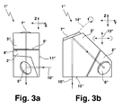
- FIG. 3a shows in a front view in the (X, Z) plane and FIG. 3b in a side view in the (Y, Z) plane a device 1 " for polarization optimization, in which the beam incidence direction of a laser beam 10" at right angles to a beam entry direction is arranged.
- the beam entry of the laser beam 10 "into a first part body 2" of the device 1 "takes place in the X direction perpendicular to a beam entry surface 11" of the first part body.
- the laser beam 10 is linearly polarized prior to reflection on a phase shifter mirror 5" with a polarization direction 13 " in the Z direction
- the laser beam 10" could alternatively also be polarized in the Y direction, as indicated by the double arrow in parentheses.
- the surface normal of the phase shift mirror 5 " is rotated by an angle of 45 ° with respect to the (Y, Z) plane, that in the X direction on the phase shifter mirror 5 "incident laser beam 10" is reflected by this in the (Y, Z) plane and meets a deflecting mirror 7 ", which is mounted on an outer side of a second part of the body 3" .
- the laser beam 10 is deflected in the Z direction by the deflection mirror 7" whose surface normal also lies in the (Y, Z) plane and leaves the device 1 "through a beam exit surface 12" of the second part body 3 ".
- the rotation about the angle ⁇ is analogous as in Figs. 1 and 2 about an axis of rotation 14 ", which is aligned perpendicular to the plane of incidence of the phase shifter mirror 5", wherein the position of the axis of rotation is not predetermined.
- the first sub-body 2 In a plane formed by an outer side 8 "of the first sub-body 2" and an adjacent outer side 9 "of the second sub-body 3", the first sub-body 2 "can be corrected with respect to the second sub-body 3" by the rotation about the second sub-body 3 " Angle ⁇ is caused to be shifted.
- phase shift mirror is operated at a different angle of incidence.
- suitable measuring optics at the position of the removed cutting head caused by deflecting mirror Phase shift be adjusted for the first time at the start of operation of the laser cutting system.
- the rotation of the device about the axis of rotation and the displacement of the body parts against each other are accomplished by means of suitable rotating units or displacement units, as they are familiar to the expert in the field of optics.
- FIG. 4 shows the construction of a laser processing system 21 for laser cutting with a CO 2 laser 22, a laser processing head 24 and a workpiece support 25 .
- a generated laser beam 26 is guided by means of deflecting mirrors to the laser processing head 24 and directed by means of mirrors on a workpiece 28 .
- the device according to the invention can be installed at any point.
- the laser beam 26 Before a continuous kerf is formed, the laser beam 26 must penetrate the workpiece 28.
- the sheet 8 must be spot-molten or oxidized at one point, and the melt must be blown out.
- laser power can be gradually increased, reduced, and held constant for a period of time until the piercing hole is created.
- Both piercing and laser cutting are assisted by the addition of a gas.
- cutting gases 29 oxygen, nitrogen, compressed air and / or application-specific gases can be used. Which gas is ultimately used depends on which materials are cut and what quality requirements are placed on the workpiece.
- the material is melted and oxidized for the most part.
- the resulting melt is blown out together with the iron oxides.
- Resulting particles and gases can be sucked out of a suction chamber 31 by means of a suction device 30 .
Landscapes
- Physics & Mathematics (AREA)
- Optics & Photonics (AREA)
- Engineering & Computer Science (AREA)
- Plasma & Fusion (AREA)
- Mechanical Engineering (AREA)
- General Physics & Mathematics (AREA)
- Electromagnetism (AREA)
- Laser Beam Processing (AREA)
- Lasers (AREA)
- Laser Surgery Devices (AREA)
- Semiconductor Lasers (AREA)
Abstract
Description
- Die vorliegende Erfindung betrifft eine Vorrichtung zur Beeinflussung der Polarisation einer Laserstrahlung mithilfe eines phasenschiebenden Elements und eines die Laserstrahlung umlenkenden Elements.
- Für eine richtungsunabhängige Bearbeitung von Werkstücken beim Laserschneiden ist ein hoher zirkularer Polarisationsgrad der Laserstrahlung am Schneidkopf von Laserschneidmaschinen erforderlich. Die aus einem Resonator ohne den Einsatz zusätzlicher optischer Elemente austretende Laserstrahlung ist jedoch in der Regel linear polarisiert.
- Aus der
DE 31 49 004 A1 ist es bekannt, eine linear polarisierte Laserstrahlung in eine zirkular polarisierte Laserstrahlung umzuwandeln. Hierzu soll eine λ/4-Platte verwendet werden. Dieselbe Funktion kann auch ein Phasenschieberspiegel erfüllen. Ein idealer Phasenschieberspiegel erzeugt bei geeignetem Inzidenzwinkel eine Phasenverschiebung um 90° zwischen einer Polarisationskomponente (s-Polarisation), welche senkrecht zu einer Einfallsebene ausgerichtet ist, und einer Polarisationskomponente (p-Polarisation), welche parallel zur Einfallsebene ausgerichtet ist. Unter der Einfallsebene wird eine Ebene verstanden, die von der Flächennormalen des Phasenschieberspiegels und einem einfallenden Laserstrahl gebildet wird. Durch die Phasenverschiebung um 90° kann aus linearer Polarisation zirkulare Polarisation erzeugt werden (und umgekehrt). - Die mithilfe des phasenschiebenden Elements erzeugte, zirkular polarisierte Laserstrahlung wird an einem die Laserstrahlung umlenkenden Element, wie einem Umlenkspiegel, reflektiert, bevor sie die Vorrichtung zur Beeinflussung der Polarisation verlässt. Der Umlenkspiegel dient für gewöhnlich zur Ausrichtung der aus der Vorrichtung austretenden Laserstrahlung.
- Zwischen Laserquelle und Bearbeitungskopf ist eine beliebige Anzahl von Strahlumlenkelementen (Spiegeln) im Strahlverlauf realisiert, wobei die Vorrichtung in diesem Strahlverlauf an beliebiger Stelle positioniert werden kann. Die Spiegel weisen zwar oft eine dielektrische Beschichtung auf, welche verhindern soll, dass bei der Reflexion an ihnen eine Phasenverschiebung auftritt. Das Auftreten einer Phasenverschiebung kann jedoch nicht vollständig verhindert werden, so dass die am Schneidkopf ankommende Laserstrahlung nicht mehr vollständig zirkular polarisiert ist.
- Aus der
DE 4434504 ist eine Laserschneidmaschine bekannt, bei der ein erster Umlenkspiegel ein zirkular polarisierender Phasenschieberspiegel ist, und bei der ein zweiter bis fünfter Umlenkspiegel derart im Strahlengang angeordnet sind, dass Phasenverschiebungen ausgeglichen werden können, die für Umlenkspiegel spezifisch sind. Zur Kompensation der Phasenverschiebungen sind dort vier Umlenkspiegel notwendig. - Demgegenüber ist es ist die Aufgabe der vorliegenden Erfindung, eine Vorrichtung der eingangs genannten Art dahingehend weiterzubilden, dass eine Kompensation von Phasenverschiebungen unter Einsatz möglichst weniger optischer Elemente erreicht werden kann.
- Diese Aufgabe wird erfindungsgemäß durch eine Vorrichtung der eingangs genannten Art gelöst, bei der das phasenschiebende Element im Bereich einer Außenseite eines ersten Teilkörpers und das umlenkende Element im Bereich einer Außenseite eines zweiten Teilkörpers angebracht ist, wobei der erste Teilkörper und der zweite Teilkörper um einen vorgebbaren Drehwinkel um eine gemeinsame Drehachse drehbar sind. Die Teilkörper können Vollkörper beispielsweise aus Aluminium mit Aperturen und Strahlführungskanälen oder transparente Körper sein.
- Mit der erfindungsgemäßen Vorrichtung lässt sich der zirkulare Polarisationsgrad wesentlich optimieren, ohne dass zusätzliche optische Elemente erforderlich wären. Insbesondere ist es möglich, die Phasenabweichungen der vor- und nachgeordneten Umlenkspiegel (in ihrer Summe) zu korrigieren.
- Je nach Inzidenzwinkel der einfallenden Laserstrahlung auf das phasenschiebende Element bewirkt dieses je nach Art der phasenschiebenden Beschichtung eine Phasenverschiebung, so dass bei einer einfallenden, linear polarisierten Laserstrahlung eine ausfallende, zirkular polarisierte Laserstrahlung erhalten werden kann. Die Kompensation der Phasenabweichungen der einzelnen Umlenkspiegel, welche dazu führen, dass keine vollständig zirkular polarisierte Laserstrahlung am Schneidkopf ankommt, erfolgt über die Justage des Drehwinkels der gesamten erfindungsgemäßen Vorrichtung.
- Durch die Bauweise der Vorrichtung wird sichergestellt, dass bei der Drehung die Richtungen von ein- und ausfallender Laserstrahlung unverändert bleiben. Zum Ausgleich eines Strahlversatzes erfolgt eine Verschiebung des ersten Teilkörpers relativ zum zweiten Teilkörper. Hierdurch wird sichergestellt, dass die ausfallende Laserstrahlung sowohl ihre Richtung als auch ihre Lage beibehält, wenn durch die Drehung die Polarisationsoptimierung vorgenommen wird.
- In einer vorteilhaften Ausführungsform ist die Drehachse senkrecht zu einer Lichteinfallsebene des phasenschiebenden Elements ausgerichtet. Die Lichteinfallsebene wird durch die Richtung der einfallenden Laserstrahlung und die Normalenrichtung des phasenschiebenden Elements festgelegt. Durch diese Anordnung der Drehachse wird sichergestellt, dass die Laserstrahlung auch nach der Reflexion auch bei einer Drehung um die Drehachse weiterhin in der Einfallsebene des phasenschiebenden Elements verläuft.
- In einer vorteilhaften Ausführungsform sind der Umlenkspiegel und das phasenschiebende Element derart angeordnet, dass einfallende und ausfallende Laserstrahlung in diesem Fall parallel und um einen vorgebbaren Betrag zueinander versetzt verlaufen.
- In einer bevorzugten Weiterbildung dieser Ausführungsform sind der Umlenkspiegel und das phasenschiebende Element derart angeordnet, dass einfallende und ausfallende Laserstrahlung für gewöhnlich parallel zueinander, aber in entgegengesetzter Richtung verlaufen.
- In einer alternativen Ausführungsform sind der Umlenkspiegel und das phasenschiebende Element derart angeordnet, dass eine Umlenkung der ausfallenden Laserstrahlung um 90° im Vergleich zur einfallenden Laserstrahlung bewirkt wird.
- Drei bevorzugte Ausführungsbeispiele der Erfindung werden anhand der schematischen Zeichnung erläutert. Es zeigt:
- Figur 1a,b
- eine erste Ausführungsform einer Vorrichtung zur Polarisationsoptimierung mit einem parallel zu einem Phasenschieberspiegel angeordneten Umlenkspiegel in einer Vorderansicht und einer Seitenansicht;
- Figur 2
- eine zweite Ausführungsform einer Vorrichtung zur Polarisationsoptimierung mit einem senkrecht zu einem Phasenschieberspiegel angeordneten Umlenkspiegel;
- Figur 3a,b
- eine dritte Ausführungsform einer Vorrichtung zur Polarisationsoptimierung mit einem unter einem Winkel zu einem Phasenschieberspiegel angeordneten Umlenkspiegel in einer Vorderansicht und einer Seitenansicht, und
- Figur 4
- eine Laserschneidanlage.
- Die Figur 1a zeigt einer Vorderansicht in der (X, Y)-Ebene und in Figur 1b in einer Seitenansicht in der (Y, Z)-Ebene gezeigte Vorrichtung 1 zur Beeinflussung der Polarisation einer Laserstrahlung, wie sie in einer in Figur 4 bildlich dargestellten Laserschneidmaschine zum Einsatz kommen kann. Die Vorrichtung 1 weist einen ersten Teilkörper 2 und einen zweiten Teilkörper 3 mit Strahlführungskanälen auf. Der erste Teilkörper 2 weist an einer Außenseite 4 einen Phasenschieberspiegel 5 auf. Der zweite Teilkörper 3 weist an einer Außenseite 6 einen Umlenkspiegel 7 auf. Eine Außenseite 8 des ersten Teilkörpers 2 und eine Außenseite 9 des zweiten Teilkörpers 3 sind entlang einer gemeinsamen Ebene verschiebbar angeordnet.
- Ein Laserstrahl 10 tritt senkrecht zu einer Strahleintrittsfläche 11 des ersten Teilkörpers 2 ein und wird an dem bezüglich der Strahleintrittsfläche unter einem Winkel von 45° angeordneten Phasenschieberspiegel 5 um 90° in Richtung auf den Umlenkspiegel 7 abgelenkt. Am Umlenkspiegel wird der Laserstrahl 10 noch einmal um 90° in der (X,Y)-Ebene abgelenkt und tritt im rechten Winkel durch eine zur Strahleintrittsfläche 11 parallele Strahlaustrittsfläche 12 des zweiten Teilkörpers 3 aus, die unter einem Winkel von 45° bezüglich des Umlenkspiegels 7 angeordnet ist. Der Laserstrahl 10 behält beim Durchtritt durch die Vorrichtung 1 seine Richtung bei, wobei er in Y-Richtung um einen durch die Bauart der Vorrichtung 1 vorgegebenen Betrag versetzt wird. Die Anordnung von Umlenkspiegel 7 und Phasenschieberspiegel 5 kann bezogen auf die Strahlrichtung auch umgekehrt sein.
- In der in Fig. 1 gezeigten Vorrichtung ist der Laserstrahl 10 vor der Reflexion an dem Phasenschieberspiegel 5 (weitgehend) linear polarisiert, und zwar mit einer Polarisationsrichtung 13, die unter einem Winkel von 45° bezüglich der (X,Y)-Ebene ausgerichtet ist. Um nach der Reflexion am Phasenschieberspiegel 5 zirkulare Polarisation zu erhalten, muss der Betrag der Feldstärken der elektrischen Lichtwelle des einfallenden Strahls senkrecht zur Einfallsebene (s-Polarisation) gleich groß sein wie der Betrag parallel zur Einfallsebene (p-Polarisation), was durch die Ausrichtung der Polarisationsrichtung 13 unter 45° zur Einfallsebene gewährleistet werden kann.
- Der Phasenschieberspiegel 5 ist unter einem Winkel von 45° bezüglich des einfallenden Laserstrahls 10 angeordnet und weist eine Phasenschiebecharakteristik in Abhängigkeit vom Einfallswinkel auf, die bei einem Einfallswinkel von 45° eine Phasenverschiebung um 90° bewirkt. Die Vorrichtung 1, wie sie in Fig. 1 gezeigt ist, dient somit der Umwandlung eines einfallenden, linear polarisierten Laserstrahls 10 in einen ausfallenden, zirkular polarisierten Laserstrahl 10 durch Reflexion am Phasenschieberspiegel 5.
- Der Zweck der Vorrichtung 1 besteht nun darin, Abweichungen von der zirkularen Polarisation des Laserstrahls 10, der die Vorrichtung 1 verlässt, so einzujustieren, dass zusammen mit den Abweichungen der übrigen Umlenkspiegel der Strahlführung eine optimal mögliche Güte der zirkularen Polarisation am Laserbearbeitungskopf (Laserschneidkopf) ankommt. Diese Abweichungen können z.B. durch Phasenverschiebungen an Umlenkspiegeln auftreten. Die Abweichung von der zirkularen Polarisation kann an einem in Figur 4 bildlich dargestellten Schneidkopf der Laserschneidanlage mittels eines geeigneten optischen Sensors ermittelt werden.
- Zur Korrektur der Phasenfehler muss der Einfallswinkel, unter dem der Laserstrahl 10 auf den Phasenschieberspiegel 5 auftrifft, verändert werden. Dies soll durch Drehung um eine Drehachse 14 geschehen, welche senkrecht zur Einfallsebene ((X,Y)-Ebene) des Laserstrahls 10 auf den Phasenschieberspiegel 5 ausgerichtet ist (d.h. in Z-Richtung). Die Drehachse 14 verläuft in Fig. 1 unterhalb des Mittelpunkts des scheibenförmigen Phasenschieberspiegels 5, kann aber entlang der Y-Richtung an einen beliebigen anderen Ort verschoben sein. Die Drehachse muss nicht zwingend durch den Mittelpunkt verlaufen.
- Durch Drehung um die Drehachse 14 wird die gesamte Vorrichtung 1 um einen Drehwinkel α gedreht. Durch die Drehung verändert sich der Einfallswinkel des Laserstrahls 10 und damit die durch den Phasenschieberspiegel 5 hervorgerufene Phasenverschiebung, welche von der Art der Beschichtung abhängig ist. Eine Abschätzung ergibt, dass sich die erforderlichen Drehwinkel α im Bereich unterhalb von 2° bewegen.
- Durch die parallele Ausrichtung des Phasenschieberspiegels 5 und des Umlenkspiegels 7 ist die Richtung des Laserstrahls 10 beim Austritt aus der Vorrichtung 1 identisch mit der Richtung beim Eintritt. Ein über den Strahlversatz in Y-Richtung, wie er bei der ungedrehten, in Fig. 1 gezeigten Vorrichtung vorhanden ist, hinausgehender Strahlversatz wird durch die Drehung um den Drehwinkel a hervorgerufen. Dieser Strahlversatz kann durch eine Verschiebung des ersten Teilkörpers 2 relativ zum zweiten Teilkörper 3 entlang einer Ebene in (X,Z)-Richtung, die von den beiden aneinander anliegenden Außenseiten 8, 9 der Vorrichtung 1 gebildet wird, kompensiert werden. Hierdurch ist gewährleistet, dass eine Polarisationsoptimierung stattfindet, ohne dass sich die Lage und Richtung des austretenden Laserstrahls 10 verändern.
- Es sei noch darauf hingewiesen, dass selbstverständlich die Strahleinfalls- und Ausfallsrichtungen vertauscht werden können und auch ein spiegelbildlicher Aufbau der Vorrichtung 1 möglich ist.
- Figur 2 zeigt eine Vorrichtung 1', welche im Aufbau und in der Funktionsweise der Vorrichtung 1 von Fig. 1 entspricht. Ein erster Teilkörper 2' weist einen Phasenschieberspiegel 5', ein zweiter Teilkörper 3' einen Umlenkspiegel 7' auf. Eine Strahleintrittsfläche 11' des ersten Teilkörpers 2' und eine Strahlaustrittsfläche 12' des zweiten Teilkörpers 3' liegen in einer gemeinsamen Ebene. Die Strahlausfallsrichtung eines aus der Vorrichtung austretenden Laserstrahls 10' ist hierbei der Strahleinfallsrichtung entgegengesetzt.
- Figur 3a zeigt in einer Vorderansicht in der (X, Z)-Ebene und Fig. 3b in einer Seitenansicht in der (Y, Z)-Ebene eine Vorrichtung 1" zur Polarisationsoptimierung, bei der die Strahleinfallsrichtung eines Laserstrahls 10" rechtwinklig zu einer Strahleintrittsrichtung angeordnet ist. Der Strahleintritt des Laserstrahls 10" in einen ersten Teilkörper 2" der Vorrichtung 1" erfolgt in X-Richtung senkrecht zu einer Strahleintrittsfläche 11" des ersten Teilkörpers. Der Laserstrahl 10" ist vor der Reflexion an einem Phasenschieberspiegel 5" linear polarisiert, und zwar mit einer Polarisationsrichtung 13" in Z-Richtung. Der Laserstrahl 10" könnte alternativ auch in Y-Richtung polarisiert sein, wie durch den Doppelpfeil in Klammern angedeutet. Die Flächennormale des Phasenschieberspiegels 5" ist in Bezug auf die (Y,Z)-Ebene um einen Winkel von 45° gedreht. Der in X-Richtung auf den Phasenschieberspiegel 5" auftreffende Laserstrahl 10" wird von diesem in die (Y,Z)-Ebene reflektiert und trifft auf einen Umlenkspiegel 7", der an einer Außenseite eines zweiten Teilkörpers 3" angebracht ist. Der Laserstrahl 10" wird durch den Umlenkspiegel 7", dessen Flächennormale ebenfalls in der (Y,Z)-Ebene liegt, in Z-Richtung umgelenkt und verlässt die Vorrichtung 1" durch eine Strahlaustrittsfläche 12" des zweiten Teilkörpers 3".
- Die Drehung um den Winkel α erfolgt analog wie in den Fig. 1 und 2 um eine Drehachse 14", welche senkrecht zur Einfallsebene des Phasenschieberspiegels 5" ausgerichtet ist, wobei die Lage der Drehachse nicht vorgegeben ist. In einer von einer Außenseite 8" des ersten Teilkörpers 2" und einer angrenzenden Außenseite 9" des zweiten Teilkörpers 3" gebildeten Ebene kann der erste Teilkörper 2" in Bezug auf den zweiten Teilkörper 3" zur Korrektur eines Strahlversatzes, der durch die Drehung um den Winkel α hervorgerufen wird, verschoben werden.
- Selbstverständlich ist es auch möglich, Vorrichtungen herzustellen, die einen anderen als einen zirkularen Polarisationsgrad am Schneidkopf einstellen, indem der Phasenschieberspiegel unter einem anderen Einfallswinkel betrieben wird. Durch geeignete Messoptiken an der Position des ausgebauten Schneidkopfs kann die durch Umlenkspiegel hervorgerufene Phasenverschiebung erstmals am Betriebsbeginn der Laserschneidanlage justiert werden. Es ist alternativ auch möglich, das Messergebnis zur Anpassung der Phasenverschiebung in einem Regelkreis zu verwenden, so dass Phasenverschiebungen, die während des Betriebs der Laserschneidanlage z.B. durch Temperaturveränderungen hervorgerufen werden, kompensiert werden können. Die Drehung der Vorrichtung um die Drehachse sowie die Verschiebung der Teilkörper gegeneinander werden mittels geeigneter Dreheinheiten bzw. Verschiebeeinheiten bewerkstelligt, wie sie dem Fachmann auf dem Gebiet der Optik geläufig sind.
- Aus der Figur 4 ist der Aufbau einer Laserbearbeitungsanlage 21 zum Laserschneiden mit einem CO2-Laser 22, einem Laserbearbeitungskopf 24 und einer Werkstückauflage 25 ersichtlich. Ein erzeugter Laserstrahl 26 wird mithilfe von Umlenkspiegeln zum Laserbearbeitungskopf 24 geführt und mithilfe von Spiegeln auf ein Werkstück 28 gerichtet. In die Strahlführung des Laserstrahls 26 kann die erfindungsgemäße Vorrichtung an beliebiger Stelle eingebaut werden.
- Bevor eine durchgängige Schnittfuge entsteht, muss der Laserstrahl 26 das Werkstück 28 durchdringen. Das Blech 8 muss an einer Stelle punktförmig geschmolzen oder oxidiert werden, und die Schmelze muss ausgeblasen werden.
- Beim langsamen Einstechen mit einer Rampe kann die Laserleistung allmählich erhöht, reduziert und über einen bestimmten Zeitraum konstant gehalten werden, bis das Einstechloch erzeugt ist. Sowohl das Einstechen als auch das Laserschneiden werden durch Hinzufügen eines Gases unterstützt. Als Schneidgase 29 können Sauerstoff, Stickstoff, Druckluft und/oder anwendungsspezifische Gase eingesetzt werden. Welches Gas letztendlich verwendet wird, ist davon abhängig, welche Materialien geschnitten und welche Qualitätsansprüche an das Werkstück gestellt werden.
- Dort, wo der Laserstrahl 26 auf das Blech 28 auftrifft, wird das Material geschmolzen und zum größten Teil oxidiert. Die entstandene Schmelze wird zusammen mit den Eisenoxiden ausgeblasen. Entstehende Partikel und Gase können mithilfe einer Absaugeinrichtung 30 aus einer Absaugkammer 31 abgesaugt werden.
Claims (6)
- Vorrichtung (1; 1'; 1") zur Beeinflussung der Polarisation einer Laserstrahlung mithilfe eines phasenschiebenden Elements (5; 5'; 5") und eines die Laserstrahlung umlenkenden Elements (7; 7'; 7"), dadurch gekennzeichnet, dass das phasenschiebende Element (5; 5'; 5") im Bereich einer Außenseite (4) eines ersten Teilkörpers (2; 2'; 2") und das umlenkende Element (7; 7'; 7") im Bereich einer Außenseite (6) eines zweiten Teilkörpers (3; 3'; 3") angebracht ist, wobei der erste Teilkörper (2; 2'; 2") und der zweite Teilkörper (3; 3';3") um einen vorgebbaren Drehwinkel (α) um eine gemeinsame Drehachse (14; 14") drehbar sind.
- Vorrichtung nach Anspruch 1, dadurch gekennzeichnet, dass zwei weitere Außenseiten (8, 9; 8",9") der beiden Teilkörper (2, 3; 2', 3'; 2", 3") einander gegenüber liegend verschiebbar angeordnet sind.
- Vorrichtung nach Anspruch 1, dadurch gekennzeichnet, dass die Drehachse (14; 14") senkrecht zur einer Lichteinfallsebene des phasenschiebenden Elements (5; 5'; 5") ausgerichtet ist.
- Vorrichtung nach einem der vorhergehenden Ansprüche, dadurch gekennzeichnet, dass das umlenkende Element (7) und das phasenschiebende Element (5) derart angeordnet sind, dass einfallende und ausfallende Laserstrahlung in diesem Fall parallel und um einen vorgebbaren Betrag zueinander versetzt verlaufen.
- Vorrichtung nach einem der vorhergehenden Ansprüche, dadurch gekennzeichnet, dass das umlenkende Element (7') und das phasenschiebende Element (5') derart angeordnet sind, dass einfallende und ausfallende Laserstrahlung für gewöhnlich parallel zueinander, aber in entgegengesetzter Richtung verlaufen.
- Vorrichtung nach einem der vorhergehenden Ansprüche, dadurch gekennzeichnet, dass das umlenkende Element (7") und das phasenschiebende Element (5") derart angeordnet sind, dass eine Umlenkung der ausfallenden Laserstrahlung um 90° im Vergleich zur einfallenden Laserstrahlung bewirkt wird.
Priority Applications (6)
| Application Number | Priority Date | Filing Date | Title |
|---|---|---|---|
| PL05014867T PL1742307T3 (pl) | 2005-07-08 | 2005-07-08 | Przyrząd wpływający na polaryzację wiązki laserowej |
| DE502005005117T DE502005005117D1 (de) | 2005-07-08 | 2005-07-08 | Vorrichtung zur Beeinflussung der Polarisation einer Laserstrahlung |
| EP05014867A EP1742307B1 (de) | 2005-07-08 | 2005-07-08 | Vorrichtung zur Beeinflussung der Polarisation einer Laserstrahlung |
| ES05014867T ES2313155T3 (es) | 2005-07-08 | 2005-07-08 | Sistema para influir sobre la polarizacion de una radiacion laserica. |
| AT05014867T ATE405975T1 (de) | 2005-07-08 | 2005-07-08 | Vorrichtung zur beeinflussung der polarisation einer laserstrahlung |
| US11/483,405 US7573636B2 (en) | 2005-07-08 | 2006-07-07 | Systems for influencing laser beam polarization |
Applications Claiming Priority (1)
| Application Number | Priority Date | Filing Date | Title |
|---|---|---|---|
| EP05014867A EP1742307B1 (de) | 2005-07-08 | 2005-07-08 | Vorrichtung zur Beeinflussung der Polarisation einer Laserstrahlung |
Publications (2)
| Publication Number | Publication Date |
|---|---|
| EP1742307A1 true EP1742307A1 (de) | 2007-01-10 |
| EP1742307B1 EP1742307B1 (de) | 2008-08-20 |
Family
ID=35344674
Family Applications (1)
| Application Number | Title | Priority Date | Filing Date |
|---|---|---|---|
| EP05014867A Expired - Lifetime EP1742307B1 (de) | 2005-07-08 | 2005-07-08 | Vorrichtung zur Beeinflussung der Polarisation einer Laserstrahlung |
Country Status (6)
| Country | Link |
|---|---|
| US (1) | US7573636B2 (de) |
| EP (1) | EP1742307B1 (de) |
| AT (1) | ATE405975T1 (de) |
| DE (1) | DE502005005117D1 (de) |
| ES (1) | ES2313155T3 (de) |
| PL (1) | PL1742307T3 (de) |
Cited By (1)
| Publication number | Priority date | Publication date | Assignee | Title |
|---|---|---|---|---|
| US10884255B2 (en) | 2015-10-14 | 2021-01-05 | Trumpf Lasersystems For Semiconductor Manufacturing Gmbh | Linear polarization of a laser beam |
Families Citing this family (3)
| Publication number | Priority date | Publication date | Assignee | Title |
|---|---|---|---|---|
| US20130032580A1 (en) * | 2010-11-29 | 2013-02-07 | Mitsubishi Electric Corporation | Optical path structure of laser processing machine |
| CN103192179B (zh) * | 2013-04-26 | 2015-06-17 | 云南玉溪水松纸厂 | 激光打孔设备的偏振装置 |
| DE102024109607A1 (de) * | 2024-04-05 | 2025-10-09 | TRUMPF Lasersystems for Semiconductor Manufacturing SE | Optische Vorrichtung und Verfahren zum Ändern einer Polarisation eines polarisierten Lichtstrahls |
Citations (6)
| Publication number | Priority date | Publication date | Assignee | Title |
|---|---|---|---|---|
| DE3149044A1 (de) * | 1980-12-15 | 1982-10-28 | Photon Sources Inc.,, Livonia, Mich. | Verfahren und vorrichtung zum abschneiden eines werkstueckteils mittels laserstrahlen |
| DE4434504A1 (de) * | 1993-09-27 | 1995-03-30 | Mitsubishi Electric Corp | Laserschneidemaschine |
| EP0695599A1 (de) * | 1994-01-20 | 1996-02-07 | Fanuc Ltd. | Laseroszillator |
| EP0818857A1 (de) * | 1996-07-11 | 1998-01-14 | Nec Corporation | Halbleiterlasereinheit mit Stabilisation der Wellenlänge und Leistung |
| US5878067A (en) * | 1994-08-10 | 1999-03-02 | Fanuc Ltd. | Laser oscillator |
| US6342981B1 (en) * | 1999-09-21 | 2002-01-29 | Rose Research, Llc | Zero-displacement phase retarder device and method |
Family Cites Families (11)
| Publication number | Priority date | Publication date | Assignee | Title |
|---|---|---|---|---|
| US3192824A (en) * | 1960-12-20 | 1965-07-06 | Kollsman Instr Corp | Scanning system for light tracking device |
| DE3149004A1 (de) | 1981-12-10 | 1983-06-16 | Grünzweig + Hartmann und Glasfaser AG, 6700 Ludwigshafen | Durch pressen verdichteter waermedaemmkoerper aus einem hochdispersen daemmaterial |
| US4643576A (en) * | 1984-04-19 | 1987-02-17 | Ricoh Company Ltd. | Fringe scanning shearing interferometer |
| DE3829708A1 (de) * | 1988-09-01 | 1990-03-15 | Zeiss Carl Fa | Umschaltbarer winkelspiegel fuer periskope |
| US5483342A (en) * | 1993-06-25 | 1996-01-09 | Hughes Aircraft Company | Polarization rotator with frequency shifting phase conjugate mirror and simplified interferometric output coupler |
| EP0648569B1 (de) * | 1993-10-18 | 1998-04-29 | Denyo Kabushiki Kaisha | Lichtbogenschweissen mit einem die Leistung versorgenden Motor |
| US5469236A (en) * | 1995-01-19 | 1995-11-21 | Roessel/Cpt, Inc. | Snorkel lens system |
| WO1996029765A1 (en) * | 1995-03-23 | 1996-09-26 | Coherent, Inc. | Prism folded laser cavity with controlled intracavity beam polarization |
| JP3224718B2 (ja) * | 1995-08-15 | 2001-11-05 | レーザーテック株式会社 | 干渉計 |
| US6020992A (en) * | 1997-06-16 | 2000-02-01 | Laser Power Corporation | Low absorption coatings for infrared laser optical elements |
| TW524966B (en) * | 1998-02-05 | 2003-03-21 | Nat Science Council | Image capturing type optical wavefront measurement device |
-
2005
- 2005-07-08 ES ES05014867T patent/ES2313155T3/es not_active Expired - Lifetime
- 2005-07-08 DE DE502005005117T patent/DE502005005117D1/de not_active Expired - Lifetime
- 2005-07-08 EP EP05014867A patent/EP1742307B1/de not_active Expired - Lifetime
- 2005-07-08 PL PL05014867T patent/PL1742307T3/pl unknown
- 2005-07-08 AT AT05014867T patent/ATE405975T1/de not_active IP Right Cessation
-
2006
- 2006-07-07 US US11/483,405 patent/US7573636B2/en active Active
Patent Citations (6)
| Publication number | Priority date | Publication date | Assignee | Title |
|---|---|---|---|---|
| DE3149044A1 (de) * | 1980-12-15 | 1982-10-28 | Photon Sources Inc.,, Livonia, Mich. | Verfahren und vorrichtung zum abschneiden eines werkstueckteils mittels laserstrahlen |
| DE4434504A1 (de) * | 1993-09-27 | 1995-03-30 | Mitsubishi Electric Corp | Laserschneidemaschine |
| EP0695599A1 (de) * | 1994-01-20 | 1996-02-07 | Fanuc Ltd. | Laseroszillator |
| US5878067A (en) * | 1994-08-10 | 1999-03-02 | Fanuc Ltd. | Laser oscillator |
| EP0818857A1 (de) * | 1996-07-11 | 1998-01-14 | Nec Corporation | Halbleiterlasereinheit mit Stabilisation der Wellenlänge und Leistung |
| US6342981B1 (en) * | 1999-09-21 | 2002-01-29 | Rose Research, Llc | Zero-displacement phase retarder device and method |
Cited By (1)
| Publication number | Priority date | Publication date | Assignee | Title |
|---|---|---|---|---|
| US10884255B2 (en) | 2015-10-14 | 2021-01-05 | Trumpf Lasersystems For Semiconductor Manufacturing Gmbh | Linear polarization of a laser beam |
Also Published As
| Publication number | Publication date |
|---|---|
| DE502005005117D1 (de) | 2008-10-02 |
| US20070024969A1 (en) | 2007-02-01 |
| EP1742307B1 (de) | 2008-08-20 |
| PL1742307T3 (pl) | 2009-01-30 |
| ES2313155T3 (es) | 2009-03-01 |
| ATE405975T1 (de) | 2008-09-15 |
| US7573636B2 (en) | 2009-08-11 |
Similar Documents
| Publication | Publication Date | Title |
|---|---|---|
| DE3339318C2 (de) | Laser-Bearbeitungsmaschine | |
| EP3956718B1 (de) | Bearbeitungsoptik, laserbearbeitungsvorrichtung und verfahren zur laserbearbeitung | |
| EP2596899B1 (de) | Vorrichtung und Verfahren zur Interferenzstrukturierung von flächigen Proben | |
| EP1465747B1 (de) | Laserbearbeitungsvorrichtung | |
| DE102011054941B3 (de) | Vorrichtung und Verfahren zur Korrektur der thermischen Verschiebung der Fokuslage von über Optiken geführten Laserstrahlen | |
| EP2448690B1 (de) | Verfahren und vorrichtung zum laserunterstützten biegen von werkstücken | |
| EP1907163A1 (de) | Vorrichtung zum bohren und für den materialabtrag mittels laserstrahl | |
| EP3774157A1 (de) | Vorrichtung, laserbearbeitungsmaschine und verfahren zum bearbeiten eines werkstücks | |
| EP3932609B1 (de) | Vorrichtung zur lasermaterialbearbeitung mit zwei parallel-versatz-einheiten des laserstrahles | |
| DE60006586T2 (de) | Laserstrahlvorrichtung zum zielen und verfahren zum schneiden oder markieren eines werkstücks | |
| DE102008032751B3 (de) | Laserbearbeitungsvorrichtung und Laserbearbeitungsverfahren mit Doppel- oder Mehrfachspot mittels eines Galvanoscanners | |
| EP2412471A2 (de) | Verfahren und Vorrichtung zum thermischen Bearbeiten eines Werkstücks mittels Laserstrahl | |
| EP1656234B1 (de) | Scankopf als teil einer laser bohr- und schneideinrichtung | |
| DE102004062381B4 (de) | Vorrichtung zum Umschalten eines Laserstrahls, Laserbearbeitungsvorrichtung | |
| EP1742307B1 (de) | Vorrichtung zur Beeinflussung der Polarisation einer Laserstrahlung | |
| WO2019115449A1 (de) | Verfahren und justier-einheit zur automatisierten justierung eines laserstrahls einer laserbearbeitungsmaschine, sowie laserbearbeitungsmaschine mit der justier-einheit | |
| EP1308235B1 (de) | Verfahren und Vorrichtung zur Steuerung der Laserstrahlenergie | |
| DE102011117454A1 (de) | Laserbearbeitungsvorrichtung | |
| WO2008119340A2 (de) | Vorrichtung und verfahren zur laserbearbeitung von bauteilen mit einer faser-oder scheibenlaserlichtquelle | |
| DE102022107324B4 (de) | Laserbearbeitungskopf mit Auslenkvorrichtungen | |
| WO2022074095A1 (de) | Vorrichtung zum erzeugen einer laserlinie auf einer arbeitsebene | |
| DE102006055595A1 (de) | Vorrichtung und Verfahren zur Regelung der Leistung eines Laserstrahls | |
| DE102019127973A1 (de) | Vorrichtung zur Bearbeitung eines Substrats mittels eines Laserbearbeitungskopfs | |
| DE102024113011A1 (de) | Vorrichtung und Verfahren zur Einstellung einer Neigung eines Schnittspaltes bei einem Laserschneidvorgang | |
| DE102022133073A1 (de) | Laserbearbeitungsanlage zur Bearbeitung eines Werkstücks mittels eines Ausgangslaserstrahls |
Legal Events
| Date | Code | Title | Description |
|---|---|---|---|
| PUAI | Public reference made under article 153(3) epc to a published international application that has entered the european phase |
Free format text: ORIGINAL CODE: 0009012 |
|
| AK | Designated contracting states |
Kind code of ref document: A1 Designated state(s): AT BE BG CH CY CZ DE DK EE ES FI FR GB GR HU IE IS IT LI LT LU LV MC NL PL PT RO SE SI SK TR |
|
| AX | Request for extension of the european patent |
Extension state: AL BA HR MK YU |
|
| 17P | Request for examination filed |
Effective date: 20070109 |
|
| 17Q | First examination report despatched |
Effective date: 20070208 |
|
| AKX | Designation fees paid |
Designated state(s): AT BE BG CH CY CZ DE DK EE ES FI FR GB GR HU IE IS IT LI LT LU LV MC NL PL PT RO SE SI SK TR |
|
| GRAP | Despatch of communication of intention to grant a patent |
Free format text: ORIGINAL CODE: EPIDOSNIGR1 |
|
| GRAS | Grant fee paid |
Free format text: ORIGINAL CODE: EPIDOSNIGR3 |
|
| GRAA | (expected) grant |
Free format text: ORIGINAL CODE: 0009210 |
|
| AK | Designated contracting states |
Kind code of ref document: B1 Designated state(s): AT BE BG CH CY CZ DE DK EE ES FI FR GB GR HU IE IS IT LI LT LU LV MC NL PL PT RO SE SI SK TR |
|
| REG | Reference to a national code |
Ref country code: GB Ref legal event code: FG4D Free format text: NOT ENGLISH |
|
| REG | Reference to a national code |
Ref country code: CH Ref legal event code: EP |
|
| REG | Reference to a national code |
Ref country code: IE Ref legal event code: FG4D Free format text: LANGUAGE OF EP DOCUMENT: GERMAN |
|
| REF | Corresponds to: |
Ref document number: 502005005117 Country of ref document: DE Date of ref document: 20081002 Kind code of ref document: P |
|
| PG25 | Lapsed in a contracting state [announced via postgrant information from national office to epo] |
Ref country code: NL Free format text: LAPSE BECAUSE OF FAILURE TO SUBMIT A TRANSLATION OF THE DESCRIPTION OR TO PAY THE FEE WITHIN THE PRESCRIBED TIME-LIMIT Effective date: 20080820 Ref country code: LT Free format text: LAPSE BECAUSE OF FAILURE TO SUBMIT A TRANSLATION OF THE DESCRIPTION OR TO PAY THE FEE WITHIN THE PRESCRIBED TIME-LIMIT Effective date: 20080820 Ref country code: IS Free format text: LAPSE BECAUSE OF FAILURE TO SUBMIT A TRANSLATION OF THE DESCRIPTION OR TO PAY THE FEE WITHIN THE PRESCRIBED TIME-LIMIT Effective date: 20081220 |
|
| REG | Reference to a national code |
Ref country code: PL Ref legal event code: T3 |
|
| PG25 | Lapsed in a contracting state [announced via postgrant information from national office to epo] |
Ref country code: LV Free format text: LAPSE BECAUSE OF FAILURE TO SUBMIT A TRANSLATION OF THE DESCRIPTION OR TO PAY THE FEE WITHIN THE PRESCRIBED TIME-LIMIT Effective date: 20080820 Ref country code: SI Free format text: LAPSE BECAUSE OF FAILURE TO SUBMIT A TRANSLATION OF THE DESCRIPTION OR TO PAY THE FEE WITHIN THE PRESCRIBED TIME-LIMIT Effective date: 20080820 Ref country code: FI Free format text: LAPSE BECAUSE OF FAILURE TO SUBMIT A TRANSLATION OF THE DESCRIPTION OR TO PAY THE FEE WITHIN THE PRESCRIBED TIME-LIMIT Effective date: 20080820 |
|
| REG | Reference to a national code |
Ref country code: ES Ref legal event code: FG2A Ref document number: 2313155 Country of ref document: ES Kind code of ref document: T3 |
|
| REG | Reference to a national code |
Ref country code: IE Ref legal event code: FD4D |
|
| PG25 | Lapsed in a contracting state [announced via postgrant information from national office to epo] |
Ref country code: DK Free format text: LAPSE BECAUSE OF FAILURE TO SUBMIT A TRANSLATION OF THE DESCRIPTION OR TO PAY THE FEE WITHIN THE PRESCRIBED TIME-LIMIT Effective date: 20080820 Ref country code: IE Free format text: LAPSE BECAUSE OF FAILURE TO SUBMIT A TRANSLATION OF THE DESCRIPTION OR TO PAY THE FEE WITHIN THE PRESCRIBED TIME-LIMIT Effective date: 20080820 Ref country code: BG Free format text: LAPSE BECAUSE OF FAILURE TO SUBMIT A TRANSLATION OF THE DESCRIPTION OR TO PAY THE FEE WITHIN THE PRESCRIBED TIME-LIMIT Effective date: 20081120 |
|
| PG25 | Lapsed in a contracting state [announced via postgrant information from national office to epo] |
Ref country code: SK Free format text: LAPSE BECAUSE OF FAILURE TO SUBMIT A TRANSLATION OF THE DESCRIPTION OR TO PAY THE FEE WITHIN THE PRESCRIBED TIME-LIMIT Effective date: 20080820 Ref country code: RO Free format text: LAPSE BECAUSE OF FAILURE TO SUBMIT A TRANSLATION OF THE DESCRIPTION OR TO PAY THE FEE WITHIN THE PRESCRIBED TIME-LIMIT Effective date: 20080820 Ref country code: PT Free format text: LAPSE BECAUSE OF FAILURE TO SUBMIT A TRANSLATION OF THE DESCRIPTION OR TO PAY THE FEE WITHIN THE PRESCRIBED TIME-LIMIT Effective date: 20090120 |
|
| PLBE | No opposition filed within time limit |
Free format text: ORIGINAL CODE: 0009261 |
|
| STAA | Information on the status of an ep patent application or granted ep patent |
Free format text: STATUS: NO OPPOSITION FILED WITHIN TIME LIMIT |
|
| 26N | No opposition filed |
Effective date: 20090525 |
|
| PG25 | Lapsed in a contracting state [announced via postgrant information from national office to epo] |
Ref country code: EE Free format text: LAPSE BECAUSE OF FAILURE TO SUBMIT A TRANSLATION OF THE DESCRIPTION OR TO PAY THE FEE WITHIN THE PRESCRIBED TIME-LIMIT Effective date: 20080820 |
|
| PG25 | Lapsed in a contracting state [announced via postgrant information from national office to epo] |
Ref country code: SE Free format text: LAPSE BECAUSE OF FAILURE TO SUBMIT A TRANSLATION OF THE DESCRIPTION OR TO PAY THE FEE WITHIN THE PRESCRIBED TIME-LIMIT Effective date: 20081120 |
|
| BERE | Be: lapsed |
Owner name: TRUMPF WERKZEUGMASCHINEN G.M.B.H. + CO. KG Effective date: 20090731 |
|
| PG25 | Lapsed in a contracting state [announced via postgrant information from national office to epo] |
Ref country code: MC Free format text: LAPSE BECAUSE OF NON-PAYMENT OF DUE FEES Effective date: 20090731 |
|
| GBPC | Gb: european patent ceased through non-payment of renewal fee |
Effective date: 20090708 |
|
| PG25 | Lapsed in a contracting state [announced via postgrant information from national office to epo] |
Ref country code: GB Free format text: LAPSE BECAUSE OF NON-PAYMENT OF DUE FEES Effective date: 20090708 |
|
| PG25 | Lapsed in a contracting state [announced via postgrant information from national office to epo] |
Ref country code: BE Free format text: LAPSE BECAUSE OF NON-PAYMENT OF DUE FEES Effective date: 20090731 |
|
| PG25 | Lapsed in a contracting state [announced via postgrant information from national office to epo] |
Ref country code: GR Free format text: LAPSE BECAUSE OF FAILURE TO SUBMIT A TRANSLATION OF THE DESCRIPTION OR TO PAY THE FEE WITHIN THE PRESCRIBED TIME-LIMIT Effective date: 20081121 |
|
| PG25 | Lapsed in a contracting state [announced via postgrant information from national office to epo] |
Ref country code: AT Free format text: LAPSE BECAUSE OF NON-PAYMENT OF DUE FEES Effective date: 20090708 |
|
| PG25 | Lapsed in a contracting state [announced via postgrant information from national office to epo] |
Ref country code: LU Free format text: LAPSE BECAUSE OF NON-PAYMENT OF DUE FEES Effective date: 20090708 |
|
| PG25 | Lapsed in a contracting state [announced via postgrant information from national office to epo] |
Ref country code: HU Free format text: LAPSE BECAUSE OF FAILURE TO SUBMIT A TRANSLATION OF THE DESCRIPTION OR TO PAY THE FEE WITHIN THE PRESCRIBED TIME-LIMIT Effective date: 20090221 |
|
| PG25 | Lapsed in a contracting state [announced via postgrant information from national office to epo] |
Ref country code: CY Free format text: LAPSE BECAUSE OF FAILURE TO SUBMIT A TRANSLATION OF THE DESCRIPTION OR TO PAY THE FEE WITHIN THE PRESCRIBED TIME-LIMIT Effective date: 20080820 |
|
| REG | Reference to a national code |
Ref country code: FR Ref legal event code: PLFP Year of fee payment: 12 |
|
| REG | Reference to a national code |
Ref country code: FR Ref legal event code: PLFP Year of fee payment: 13 |
|
| REG | Reference to a national code |
Ref country code: FR Ref legal event code: PLFP Year of fee payment: 14 |
|
| PGFP | Annual fee paid to national office [announced via postgrant information from national office to epo] |
Ref country code: ES Payment date: 20190822 Year of fee payment: 15 |
|
| PGFP | Annual fee paid to national office [announced via postgrant information from national office to epo] |
Ref country code: PL Payment date: 20200619 Year of fee payment: 16 |
|
| PGFP | Annual fee paid to national office [announced via postgrant information from national office to epo] |
Ref country code: CZ Payment date: 20200707 Year of fee payment: 16 Ref country code: TR Payment date: 20200708 Year of fee payment: 16 Ref country code: FR Payment date: 20200721 Year of fee payment: 16 |
|
| PGFP | Annual fee paid to national office [announced via postgrant information from national office to epo] |
Ref country code: IT Payment date: 20200724 Year of fee payment: 16 Ref country code: CH Payment date: 20200721 Year of fee payment: 16 |
|
| REG | Reference to a national code |
Ref country code: ES Ref legal event code: FD2A Effective date: 20211228 |
|
| PG25 | Lapsed in a contracting state [announced via postgrant information from national office to epo] |
Ref country code: ES Free format text: LAPSE BECAUSE OF NON-PAYMENT OF DUE FEES Effective date: 20200709 |
|
| REG | Reference to a national code |
Ref country code: CH Ref legal event code: PL |
|
| PG25 | Lapsed in a contracting state [announced via postgrant information from national office to epo] |
Ref country code: LI Free format text: LAPSE BECAUSE OF NON-PAYMENT OF DUE FEES Effective date: 20210731 Ref country code: CH Free format text: LAPSE BECAUSE OF NON-PAYMENT OF DUE FEES Effective date: 20210731 |
|
| PG25 | Lapsed in a contracting state [announced via postgrant information from national office to epo] |
Ref country code: FR Free format text: LAPSE BECAUSE OF NON-PAYMENT OF DUE FEES Effective date: 20210731 Ref country code: CZ Free format text: LAPSE BECAUSE OF NON-PAYMENT OF DUE FEES Effective date: 20210708 |
|
| PG25 | Lapsed in a contracting state [announced via postgrant information from national office to epo] |
Ref country code: IT Free format text: LAPSE BECAUSE OF NON-PAYMENT OF DUE FEES Effective date: 20210708 |
|
| PG25 | Lapsed in a contracting state [announced via postgrant information from national office to epo] |
Ref country code: PL Free format text: LAPSE BECAUSE OF NON-PAYMENT OF DUE FEES Effective date: 20210708 |
|
| PGFP | Annual fee paid to national office [announced via postgrant information from national office to epo] |
Ref country code: DE Payment date: 20240719 Year of fee payment: 20 |
|
| REG | Reference to a national code |
Ref country code: DE Ref legal event code: R071 Ref document number: 502005005117 Country of ref document: DE |