EP1741954A2 - Ensemble volant a deux masses - Google Patents
Ensemble volant a deux masses Download PDFInfo
- Publication number
- EP1741954A2 EP1741954A2 EP06253544A EP06253544A EP1741954A2 EP 1741954 A2 EP1741954 A2 EP 1741954A2 EP 06253544 A EP06253544 A EP 06253544A EP 06253544 A EP06253544 A EP 06253544A EP 1741954 A2 EP1741954 A2 EP 1741954A2
- Authority
- EP
- European Patent Office
- Prior art keywords
- spring
- mass
- radially extending
- windows
- balance arm
- Prior art date
- Legal status (The legal status is an assumption and is not a legal conclusion. Google has not performed a legal analysis and makes no representation as to the accuracy of the status listed.)
- Withdrawn
Links
Images


Classifications
-
- F—MECHANICAL ENGINEERING; LIGHTING; HEATING; WEAPONS; BLASTING
- F16—ENGINEERING ELEMENTS AND UNITS; GENERAL MEASURES FOR PRODUCING AND MAINTAINING EFFECTIVE FUNCTIONING OF MACHINES OR INSTALLATIONS; THERMAL INSULATION IN GENERAL
- F16F—SPRINGS; SHOCK-ABSORBERS; MEANS FOR DAMPING VIBRATION
- F16F15/00—Suppression of vibrations in systems; Means or arrangements for avoiding or reducing out-of-balance forces, e.g. due to motion
- F16F15/10—Suppression of vibrations in rotating systems by making use of members moving with the system
- F16F15/12—Suppression of vibrations in rotating systems by making use of members moving with the system using elastic members or friction-damping members, e.g. between a rotating shaft and a gyratory mass mounted thereon
- F16F15/131—Suppression of vibrations in rotating systems by making use of members moving with the system using elastic members or friction-damping members, e.g. between a rotating shaft and a gyratory mass mounted thereon the rotating system comprising two or more gyratory masses
- F16F15/133—Suppression of vibrations in rotating systems by making use of members moving with the system using elastic members or friction-damping members, e.g. between a rotating shaft and a gyratory mass mounted thereon the rotating system comprising two or more gyratory masses using springs as elastic members, e.g. metallic springs
- F16F15/134—Wound springs
- F16F15/13469—Combinations of dampers, e.g. with multiple plates, multiple spring sets, i.e. complex configurations
- F16F15/13476—Combinations of dampers, e.g. with multiple plates, multiple spring sets, i.e. complex configurations resulting in a staged spring characteristic, e.g. with multiple intermediate plates
- F16F15/13484—Combinations of dampers, e.g. with multiple plates, multiple spring sets, i.e. complex configurations resulting in a staged spring characteristic, e.g. with multiple intermediate plates acting on multiple sets of springs
- F16F15/13492—Combinations of dampers, e.g. with multiple plates, multiple spring sets, i.e. complex configurations resulting in a staged spring characteristic, e.g. with multiple intermediate plates acting on multiple sets of springs the sets of springs being arranged at substantially the same radius
-
- F—MECHANICAL ENGINEERING; LIGHTING; HEATING; WEAPONS; BLASTING
- F16—ENGINEERING ELEMENTS AND UNITS; GENERAL MEASURES FOR PRODUCING AND MAINTAINING EFFECTIVE FUNCTIONING OF MACHINES OR INSTALLATIONS; THERMAL INSULATION IN GENERAL
- F16F—SPRINGS; SHOCK-ABSORBERS; MEANS FOR DAMPING VIBRATION
- F16F1/00—Springs
- F16F1/02—Springs made of steel or other material having low internal friction; Wound, torsion, leaf, cup, ring or the like springs, the material of the spring not being relevant
- F16F1/04—Wound springs
- F16F1/12—Attachments or mountings
- F16F1/125—Attachments or mountings where the end coils of the spring engage an axial insert
-
- F—MECHANICAL ENGINEERING; LIGHTING; HEATING; WEAPONS; BLASTING
- F16—ENGINEERING ELEMENTS AND UNITS; GENERAL MEASURES FOR PRODUCING AND MAINTAINING EFFECTIVE FUNCTIONING OF MACHINES OR INSTALLATIONS; THERMAL INSULATION IN GENERAL
- F16F—SPRINGS; SHOCK-ABSORBERS; MEANS FOR DAMPING VIBRATION
- F16F15/00—Suppression of vibrations in systems; Means or arrangements for avoiding or reducing out-of-balance forces, e.g. due to motion
- F16F15/10—Suppression of vibrations in rotating systems by making use of members moving with the system
- F16F15/12—Suppression of vibrations in rotating systems by making use of members moving with the system using elastic members or friction-damping members, e.g. between a rotating shaft and a gyratory mass mounted thereon
- F16F15/131—Suppression of vibrations in rotating systems by making use of members moving with the system using elastic members or friction-damping members, e.g. between a rotating shaft and a gyratory mass mounted thereon the rotating system comprising two or more gyratory masses
- F16F15/133—Suppression of vibrations in rotating systems by making use of members moving with the system using elastic members or friction-damping members, e.g. between a rotating shaft and a gyratory mass mounted thereon the rotating system comprising two or more gyratory masses using springs as elastic members, e.g. metallic springs
- F16F15/134—Wound springs
- F16F15/13415—Wound springs characterised by the dimension or shape of spring-containing windows
-
- F—MECHANICAL ENGINEERING; LIGHTING; HEATING; WEAPONS; BLASTING
- F16—ENGINEERING ELEMENTS AND UNITS; GENERAL MEASURES FOR PRODUCING AND MAINTAINING EFFECTIVE FUNCTIONING OF MACHINES OR INSTALLATIONS; THERMAL INSULATION IN GENERAL
- F16F—SPRINGS; SHOCK-ABSORBERS; MEANS FOR DAMPING VIBRATION
- F16F3/00—Spring units consisting of several springs, e.g. for obtaining a desired spring characteristic
- F16F3/02—Spring units consisting of several springs, e.g. for obtaining a desired spring characteristic with springs made of steel or of other material having low internal friction
- F16F3/04—Spring units consisting of several springs, e.g. for obtaining a desired spring characteristic with springs made of steel or of other material having low internal friction composed only of wound springs
Definitions
- the present invention relates to a twin mass flywheel assembly, hereinafter referred to as being of the type specified, including an input mass for connection with a vehicle engine and an output mass for connection with a vehicle drive line, the input and output masses being relatively rotatable against the action of a damping means acting between the input and output masses to absorb or attenuate torsional vibrations emanating from the engine, a radially extending flange secured to an outer peripheral portion of the input mass provided with a plurality of windows and an axially extending support hub secured to an inner peripheral portion of the flange, the output mass being supported from the hub.
- torsional vibration damper between the input mass and the output mass. It is known for the torsional vibration damper to comprise two pairs of compression springs housed in the plurality of windows formed in the radially extending flange and corresponding windows formed in side plates disposed to either side of the radially inwardly extending flange. The side plates are secured to the output mass by spacing rivets. Such an arrangement is known for example from EP 1 521 011 .
- the torsional damper While such an arrangement functions well, there remain areas where improved performance could be obtained.
- a twin mass flywheel of the type specified further comprises a balance arm assembly rotatably mounted to the hub, carrier means and a plurality of spring assemblies, said balance arm assembly comprising a central boss, a plurality of radially extending arms, each of said radially extending arms being adapted to locate within a corresponding one of said plurality of windows, and each of said arms being held in position in said window by a pair of spring assemblies, each of said spring assemblies being located between at a first end one end of the window and at a second end the carrier means.
- twin mass flywheel assembly further comprises side plates disposed to either side of the radially extending flange.
- a balance arm assembly comprises a hub, a radially extending flange plate secured to the hub having a plurality of circumferentially spaced windows, a balance arm member rotatably mounted to the hub, carrier means and a plurality of spring assemblies, said balance arm member comprising a central boss, a plurality of radially extending arms, each of said radially extending arms being adapted to locate within a corresponding one of said plurality of windows, and each of said arms being held in position in said window by a pair of spring assemblies, each of said spring assemblies being located between at a first end one end of the window and at a second end the carrier means.
- each spring assembly comprises a plurality of springs. More preferably, each spring assembly comprises a first compression spring, a second compression spring located within the first compression spring and a third compression spring located within the second compression spring.
- the plurality of windows is two windows.
- a spring assembly comprises a first outer spring with a second spring and a third spring located within the first spring, the second spring and the third spring being separated by a buffer piece.
- a twin mass flywheel according to the first aspect of the present invention or a balance arm assembly according to the second aspect of the invention is provided with at least two spring assemblies according to the third aspect of the present invention.
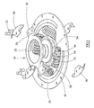
- twin mass flywheel assembly 2 comprises an input mass (not shown) and an output mass 6 which are relatively rotatable through a small angular range against a torsional vibrational damper.
- the output mass 6 is supported from the input mass via an axially extending support hub 10.
- the axially extending support hub 10 is secured to an inner peripheral portion of a radially extending flange plate 12 by any suitable means, including for example by fasteners 14 as best shown in Figure 4.
- the radially extending flange plate 12 is provided at a radially outer peripheral portion with a series of openings 16 by which the radially extending flange plate may be secured to the input mass, for example by bolts (not shown).
- the radially extending flange plate 12 is provided at an intermediate region with two circumferentially disposed windows 18.
- the radially extending flange plate 12 is provided with a further set of windows 23 disposed radially outward of the two circumferentially disposed windows 18 of the intermediate region.
- a projecting part of the output mass 6 extends through one of the further set of windows 23, the ends of the further window 23 acting as a stop to prevent further relative angular displacement of the radially extending flange plate 12 and the output mass 6. It will be understood that this is in turn defines the maximum possible relative angular displacement of the input mass and the output mass.
- the relative rotation of the input and output masses is also subject to frictional damping by friction damping means 50.
- a further member 24 is mounted on the axially extending support hub 10.
- the further member 24 comprises a central boss or ring 25 for mounting the further member 24 on the axially extending support hub 10, and a pair of radially outward extending members 26.
- Each of the radially outward extending members 26 are displaced axially from the central ring 25 by a step or shoulder 28.
- the step 28 allows each of the radially outward extending members 26 to be located within a respective window 18 in the intermediate portion of the radially extending flange plate 12. It will be understood that the radially extending members 26 are of greater axial thickness than the radially extending flange plate 12.
- the further member 24 may be formed by any convenient means, for example by pressing, forging or any other suitable means.
- each radially extending member 26 there are located a pair of carrier plates 30.
- Each plate of the pair of carrier plates 30 is secured to the other through the respective radially extending member 26 by any convenient means. In the embodiment illustrated in Figures 1 to 4 the carrier plates 30 are secured by rivets 32.
- Each of the carrier plates 30 is provided with an angularly disposed cover portion 34. At least a portion of each the carrier plates 30 extends radially outward of the two circumferentially disposed windows 18 of the intermediate region of the radially extending flange plate 12. In normal use the carrier plates 30 do not come into contact with the radially extending flange plate 12.
- the torsional vibrational damper further comprises two pairs of compression spring assemblies 40 that are housed in the series of windows 18 formed in the radially extending flange plate 12 and the windows formed in the side plates 20,22.
- a first end of each said spring assembly 40 is seated against a first end of the respective windows 18 formed in the extending flange plate and the corresponding windows formed in the side plates 20,22.
- a second end of each spring assembly 40 is seated against a side face of the radially extending member 26 and within each of the angularly disposed cover portions 34.
- the angularly disposed cover portions 34 serve to prevent the second end of each spring assembly 40 from becoming displaced in use. It can be seen that the spring assemblies 40 within each of the windows 18 locate each of the radially extending side members 26 in a rotatable or angular position.
- the sets of spring assemblies 40 in each of the two windows 18 need not be identical but should match, that is pair with, the sets of spring assemblies in the other of the two windows 18. In this instance, the rotational movement of the balance arm assembly will be directly related to the load applied by the differing sets of spring assemblies 40 on either side of the radially outward extending members 26.
- a clutch cover and drive plate may be secured to the output mass 6 of the twin mass flywheel assembly
- each of the spring assemblies 40 comprises a first compression spring 42, a second compression spring 44 located within the first compression spring 42 and a third compression spring 46 located within the second compression spring 44.
- Each of the first compression spring 42, the second compression spring 44 and the third compression spring 46 have different compression characteristics. This has as an advantage that the effective spring rate of the spring assembly 40 may be chosen to fit best the operational characteristics expected when the twin mass flywheel assembly 2 is in use.
- the spring assembly 140 comprises a first compression spring 142 and a second compression spring 144 and a third compression spring 146 each located within the first compression spring 142, the second compression spring 144 and the third compression spring 146 being separated from one another by a buffer piece 152.
- the buffer piece 152 illustrated has a central web 154.
- a first protrusion 156 extends.
- one end of the second compression spring 144 is seated against the first side of the web 154 such that the first protrusion 156 is located within one end of the second compression spring 144.
- the first protrusion 156 is a press fit within the second compression spring 144.
- a second protrusion 158 extends.
- one end of the third compression spring 146 is seated against the second side of the web 154 such that the second protrusion 156 is located within one end of the third compression spring 146.
- the second protrusion 158 is a press fit within the third compression spring 146.
- the first protrusion 156 and the second protrusion 158 share a common axis.
- Each of the first compression spring 142, the second compression spring 144 and the third compression spring 146 have different compression characteristics. This also allows the effective spring rate of the spring assembly 140 to be chosen to fit best the operational characteristics required.
Applications Claiming Priority (1)
| Application Number | Priority Date | Filing Date | Title |
|---|---|---|---|
| GB0514153A GB0514153D0 (en) | 2005-07-09 | 2005-07-09 | Twin mass flywheel assembly |
Publications (2)
| Publication Number | Publication Date |
|---|---|
| EP1741954A2 true EP1741954A2 (fr) | 2007-01-10 |
| EP1741954A3 EP1741954A3 (fr) | 2007-03-28 |
Family
ID=34897016
Family Applications (1)
| Application Number | Title | Priority Date | Filing Date |
|---|---|---|---|
| EP06253544A Withdrawn EP1741954A3 (fr) | 2005-07-09 | 2006-07-06 | Ensemble volant a deux masses |
Country Status (2)
| Country | Link |
|---|---|
| EP (1) | EP1741954A3 (fr) |
| GB (1) | GB0514153D0 (fr) |
Cited By (7)
| Publication number | Priority date | Publication date | Assignee | Title |
|---|---|---|---|---|
| FR2986590A1 (fr) * | 2012-02-07 | 2013-08-09 | Valeo Embrayages | Dispositif de transmission de couple pour un vehicule automobile |
| WO2014122367A1 (fr) * | 2013-02-11 | 2014-08-14 | Valeo Embrayages | Dispositif de transmission de couple pour un véhicule automobile |
| FR3021722A1 (fr) * | 2014-05-28 | 2015-12-04 | Valeo Embrayages | Dispositif de transmission de couple, notamment pour vehicule automobile |
| DE102014213115A1 (de) * | 2014-07-07 | 2016-01-07 | Voith Patent Gmbh | Torsionsschwingungsdämpfer |
| FR3025267A1 (fr) * | 2014-08-28 | 2016-03-04 | Valeo Embrayages | Dispositif de transmission de couple, notamment pour vehicule automobile |
| JP2016217521A (ja) * | 2015-05-26 | 2016-12-22 | アイシン精機株式会社 | トルク変動吸収装置 |
| CN107208736A (zh) * | 2015-01-26 | 2017-09-26 | 法雷奥离合器公司 | 具有直弹簧的扭转减振器 |
Citations (5)
| Publication number | Priority date | Publication date | Assignee | Title |
|---|---|---|---|---|
| GB2052682A (en) * | 1979-06-05 | 1981-01-28 | Borg Warner | Series Spring Torsional Vibration Damper |
| EP0339805A2 (fr) * | 1988-04-01 | 1989-11-02 | Toyota Jidosha Kabushiki Kaisha | Volant d'inertie du type à amortisseur de torsion avec un mécanisme d'amortissement fluide |
| GB2256914A (en) * | 1991-06-15 | 1992-12-23 | Voith Gmbh J M | A flexible clutch of disc-shaped construction |
| DE19914376A1 (de) * | 1998-04-06 | 1999-10-07 | Luk Lamellen & Kupplungsbau | Geteiltes Schwungrad |
| FR2801950A1 (fr) * | 1999-12-07 | 2001-06-08 | Mannesmann Sachs Ag | Amortisseur d'oscillations de torsion |
-
2005
- 2005-07-09 GB GB0514153A patent/GB0514153D0/en not_active Ceased
-
2006
- 2006-07-06 EP EP06253544A patent/EP1741954A3/fr not_active Withdrawn
Patent Citations (5)
| Publication number | Priority date | Publication date | Assignee | Title |
|---|---|---|---|---|
| GB2052682A (en) * | 1979-06-05 | 1981-01-28 | Borg Warner | Series Spring Torsional Vibration Damper |
| EP0339805A2 (fr) * | 1988-04-01 | 1989-11-02 | Toyota Jidosha Kabushiki Kaisha | Volant d'inertie du type à amortisseur de torsion avec un mécanisme d'amortissement fluide |
| GB2256914A (en) * | 1991-06-15 | 1992-12-23 | Voith Gmbh J M | A flexible clutch of disc-shaped construction |
| DE19914376A1 (de) * | 1998-04-06 | 1999-10-07 | Luk Lamellen & Kupplungsbau | Geteiltes Schwungrad |
| FR2801950A1 (fr) * | 1999-12-07 | 2001-06-08 | Mannesmann Sachs Ag | Amortisseur d'oscillations de torsion |
Cited By (9)
| Publication number | Priority date | Publication date | Assignee | Title |
|---|---|---|---|---|
| FR2986590A1 (fr) * | 2012-02-07 | 2013-08-09 | Valeo Embrayages | Dispositif de transmission de couple pour un vehicule automobile |
| WO2014122367A1 (fr) * | 2013-02-11 | 2014-08-14 | Valeo Embrayages | Dispositif de transmission de couple pour un véhicule automobile |
| EP2954224B1 (fr) | 2013-02-11 | 2019-05-01 | Valeo Embrayages | Dispositif de transmission de couple pour un véhicule automobile |
| FR3021722A1 (fr) * | 2014-05-28 | 2015-12-04 | Valeo Embrayages | Dispositif de transmission de couple, notamment pour vehicule automobile |
| DE102014213115A1 (de) * | 2014-07-07 | 2016-01-07 | Voith Patent Gmbh | Torsionsschwingungsdämpfer |
| FR3025267A1 (fr) * | 2014-08-28 | 2016-03-04 | Valeo Embrayages | Dispositif de transmission de couple, notamment pour vehicule automobile |
| CN107208736A (zh) * | 2015-01-26 | 2017-09-26 | 法雷奥离合器公司 | 具有直弹簧的扭转减振器 |
| CN107208736B (zh) * | 2015-01-26 | 2020-03-10 | 法雷奥凯佩科液力变矩器(南京)有限公司 | 具有直弹簧的扭转减振器 |
| JP2016217521A (ja) * | 2015-05-26 | 2016-12-22 | アイシン精機株式会社 | トルク変動吸収装置 |
Also Published As
| Publication number | Publication date |
|---|---|
| GB0514153D0 (en) | 2005-08-17 |
| EP1741954A3 (fr) | 2007-03-28 |
Similar Documents
| Publication | Publication Date | Title |
|---|---|---|
| EP1741954A2 (fr) | Ensemble volant a deux masses | |
| JPS6352256B2 (fr) | ||
| KR20110103450A (ko) | 자동차용으로 특히 적합한 유연성 플라이휠 | |
| CN101275612A (zh) | 弹簧座和减震片组件 | |
| US5823516A (en) | Torsion damping device having metallic seats for its springs, especially for a motor vehicle | |
| JP3558462B2 (ja) | フライホイール組立体 | |
| US7717792B2 (en) | Torsional detuner | |
| US5857552A (en) | Plate member having radially extending support portions for a damper disc assembly | |
| US6343684B1 (en) | Torsional vibration damper | |
| US6026710A (en) | Torsional vibration damper with a friction device | |
| KR20210118090A (ko) | 진자 댐핑 장치 | |
| US4983142A (en) | Double damped flywheel, especially for automotive vehicles | |
| JP2001304341A (ja) | シート部材、弾性部材組立体及びダンパー機構 | |
| KR102523248B1 (ko) | 토션 진동 댐핑 장치 | |
| US7166030B2 (en) | Torsional vibration damper | |
| CN106051043B (zh) | 尤其用于机动车的传递扭矩的双减振飞轮 | |
| EP1442228B1 (fr) | Volant deux masses | |
| JP4015774B2 (ja) | ダンパー機構及びダンパーディスク組立体 | |
| GB2315315A (en) | Friction clutch predamper. | |
| CN111819373B (zh) | 摆式阻尼装置 | |
| US6622842B2 (en) | Clutch disk | |
| WO2006027552A1 (fr) | Disques d'embrayage | |
| CN218670401U (zh) | 振动阻尼装置 | |
| JP3593435B2 (ja) | トルクコンバータのロックアップダンパー | |
| CN213981843U (zh) | 扭振减振器,以及离合器 |
Legal Events
| Date | Code | Title | Description |
|---|---|---|---|
| PUAI | Public reference made under article 153(3) epc to a published international application that has entered the european phase |
Free format text: ORIGINAL CODE: 0009012 |
|
| AK | Designated contracting states |
Kind code of ref document: A2 Designated state(s): AT BE BG CH CY CZ DE DK EE ES FI FR GB GR HU IE IS IT LI LT LU LV MC NL PL PT RO SE SI SK TR |
|
| AX | Request for extension of the european patent |
Extension state: AL BA HR MK YU |
|
| PUAL | Search report despatched |
Free format text: ORIGINAL CODE: 0009013 |
|
| AK | Designated contracting states |
Kind code of ref document: A3 Designated state(s): AT BE BG CH CY CZ DE DK EE ES FI FR GB GR HU IE IS IT LI LT LU LV MC NL PL PT RO SE SI SK TR |
|
| AX | Request for extension of the european patent |
Extension state: AL BA HR MK YU |
|
| 17P | Request for examination filed |
Effective date: 20070928 |
|
| 17Q | First examination report despatched |
Effective date: 20071106 |
|
| AKX | Designation fees paid |
Designated state(s): AT BE BG CH CY CZ DE DK EE ES FI FR GB GR HU IE IS IT LI LT LU LV MC NL PL PT RO SE SI SK TR |
|
| STAA | Information on the status of an ep patent application or granted ep patent |
Free format text: STATUS: THE APPLICATION IS DEEMED TO BE WITHDRAWN |
|
| 18D | Application deemed to be withdrawn |
Effective date: 20080517 |