EP1740923B1 - Hysteresis compensation system - Google Patents
Hysteresis compensation system Download PDFInfo
- Publication number
- EP1740923B1 EP1740923B1 EP05729181.7A EP05729181A EP1740923B1 EP 1740923 B1 EP1740923 B1 EP 1740923B1 EP 05729181 A EP05729181 A EP 05729181A EP 1740923 B1 EP1740923 B1 EP 1740923B1
- Authority
- EP
- European Patent Office
- Prior art keywords
- gear
- drive
- gear rack
- motor
- rack
- Prior art date
- Legal status (The legal status is an assumption and is not a legal conclusion. Google has not performed a legal analysis and makes no representation as to the accuracy of the status listed.)
- Expired - Lifetime
Links
Images


Classifications
-
- G—PHYSICS
- G01—MEASURING; TESTING
- G01N—INVESTIGATING OR ANALYSING MATERIALS BY DETERMINING THEIR CHEMICAL OR PHYSICAL PROPERTIES
- G01N35/00—Automatic analysis not limited to methods or materials provided for in any single one of groups G01N1/00 - G01N33/00; Handling materials therefor
- G01N35/10—Devices for transferring samples or any liquids to, in, or from, the analysis apparatus, e.g. suction devices, injection devices
- G01N35/1009—Characterised by arrangements for controlling the aspiration or dispense of liquids
- G01N35/1011—Control of the position or alignment of the transfer device
-
- F—MECHANICAL ENGINEERING; LIGHTING; HEATING; WEAPONS; BLASTING
- F16—ENGINEERING ELEMENTS AND UNITS; GENERAL MEASURES FOR PRODUCING AND MAINTAINING EFFECTIVE FUNCTIONING OF MACHINES OR INSTALLATIONS; THERMAL INSULATION IN GENERAL
- F16H—GEARING
- F16H19/00—Gearings comprising essentially only toothed gears or friction members and not capable of conveying indefinitely-continuing rotary motion
- F16H19/02—Gearings comprising essentially only toothed gears or friction members and not capable of conveying indefinitely-continuing rotary motion for interconverting rotary or oscillating motion and reciprocating motion
- F16H19/04—Gearings comprising essentially only toothed gears or friction members and not capable of conveying indefinitely-continuing rotary motion for interconverting rotary or oscillating motion and reciprocating motion comprising a rack
-
- F—MECHANICAL ENGINEERING; LIGHTING; HEATING; WEAPONS; BLASTING
- F16—ENGINEERING ELEMENTS AND UNITS; GENERAL MEASURES FOR PRODUCING AND MAINTAINING EFFECTIVE FUNCTIONING OF MACHINES OR INSTALLATIONS; THERMAL INSULATION IN GENERAL
- F16H—GEARING
- F16H57/00—General details of gearing
- F16H57/12—Arrangements for adjusting or for taking-up backlash not provided for elsewhere
- F16H2057/126—Self-adjusting during operation, e.g. by a spring
Definitions
- the present invention relates to a method and apparatus for economically ensuring the precise and reproducible automation of laboratory instrumentation.
- the present invention relates to precision movement of laboratory instrumentation such as pipette tips in a manner that overcomes hysteresis inherent in gear-driven positioning mechanisms.
- hysteresis indicates the inability to predict the exact location of a given component, which could result in broken instrumentation, reduced ability to uptake or adequately measure a given chemical in a chemical well, or contamination of a sample.
- GB 1 041 793 A discloses a rack and pinion mechanism in which to pinions are in driving engagement with a rack.
- Each rack pinion is driven through one of a pair of driving pinions on a driving shaft.
- One driving pinion has helical teeth and is movable axially relative to the other or fixed driving pinion.
- Means are provided for urging the axially movable driving pinion in one direction whereby the two rack pinions are rotatably biased in opposite directions due to the tooth angle of the axially movable driving pinion.
- the teeth of one rack pinion are in engagement with one side of the rack teeth and the teeth of the other rack pinion are in engagement with the other side of the rack teeth.
- US 5 206 568 discloses an automated analyzer with a drive mechanism for the pipette, comprising a gear rack and a drive mechanism. This document does not disclose any hysteresis break.
- US 2005/158076 A1 discloses an electrographic printer using a print web medium with a web adjusting apparatus having a geared motor for adjusting the web position.
- a method and apparatus to compensate for backlash in the geared motor includes a sensor to detect an end position of rotation of the geared motor. A time being determined from a point of reversal of the geared motor to a decay in the sensor output indicating a gear backlash, and the time being added to the drive of the geared motor when reversing directions to adjust the web position.
- an apparatus for providing precision linear positioning of at least one laboratory pipette comprises a rack, a drive mechanism having a drive component operable to engage a linear rack, a magnetic brake engaging the rack operable to provide a force opposing movement of the drive mechanism.
- the second embodiment could further comprise a carriage assembly holding the drive mechanism and the magnetic brake. Further, the second embodiment could additionally comprise a pipette connected to the gear rack or the carriage assembly.
- a second embodiment of the present invention is a method for compensating hysteresis in laboratory liquid handling systems comprising the steps of providing a carriage with a drive gear that engages a linear gear rack; providing a motor in connection with the drive gear via a drive train; providing a hysteresis brake engaging the gear rack; adjusting the hysteresis brake so that resistance is provided to movement of the gear rack, causing the drive gear to remain in positive engagement with the gear rack; and engaging the motor so that the drive train is positively engaged, causing the drive gear to move the gear rack in a first direction. Additionally, this method could include the step of reversing the motor so that the drive gear moves the gear rack in a second direction.
- the method could include the step of calculating an error margin caused by play in the drive train components involved in reversing direction of the gear rack.
- the method could include the step of compensating for the error margin that occurs by rotating the motor a calculated distance directly related to the error margin. The calculation of the error margin and compensation for the error margin could be accomplished by using a software program.
- the present invention relates to laboratory precision automation of instrumentation. More specifically, the invention relates to a laboratory pipetting system designed to operate in a manner such that positioning the automated pipette can be done predictably and reliably in an exact manner.
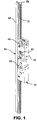
- a pipette drive assembly 10 comprises a gear rack 20 and a carriage assembly 30 engaging gear rack 20 such that carriage assembly 30 is operable to move relative to gear rack 20.
- Gear rack 20 comprises a linear member having gear teeth 21 along one side and a ridge 22 on either side of the gear teeth.
- Carriage assembly 30 comprises chassis 35, drive gear 40, pass-thru holes 43, and hysteresis brake 50. Further, drive gear 40 engageably contacts gear rack 20, and hysteresis brake 50 likewise engages gear rack 20.
- Fig. 2 shows an expanded view of pipette drive assembly 10 according to one embodiment of the present invention.
- Drive gear 41 comprises multiple gear teeth which engageably mesh with the gear teeth 21 of gear rack 20 when carriage assembly 30 is engageably mounted to gear rack 20.
- Carriage assembly 30 includes channels 33 that slidably engage the ridges 22 of gear rack 20 in a manner that properly orients the carriage assembly 30 with respect to the gear rack 20 and ensures that gear teeth 21 of gear rack 20 are a proper distance from the drive gear 41 to engage the teeth of the drive gear.
- Drive gear 41 includes a rectangular bore through its central axis designed to receive a drive shaft from a drive motor that provides torque to turn the drive gear 41.
- Hysteresis gear 51 of hysteresis brake assembly 50 also has teeth which engageably mesh with the teeth 21 of gear rack 20 when carriage assembly 30 is engageably mounted to gear rack 20. Therefore, drive gear assembly 40, if rotatably attached to a motor or some other turning force is operable to move gear rack 20 in a linear fashion relative to carriage assembly 30.
- a drive train connects an electric motor to drive gear assembly 40.
- the drive train comprise a motor, a drive shaft in the form of a square shaft extending through the center rectangular bore of drive gear assembly 40.
- the motor is signaled to rotate in a particular direction, causing adjoining square drive shaft to likewise turn and rotate drive gear assembly 40.
- the rotation of drive gear assembly 40 causes gear rack 20 to move relative to carriage assembly 30.
- Any number of additional drive components could also be used to provide translation of a force from the electric motor to the carriage assembly or rack, causing movement.
- Each permutation of a drive train or drive mechanism would transfer a force into movement of the carriage assembly or rack.
- each connection point or component within the drive train offers an addition of mechanical play where hysteresis is introduced.
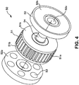
- Fig. 3 shows a perspective view of hysteresis brake assembly 50, a component of pipette drive assembly 10 shown in Figs. 1 and 2 .
- Fig. 4 shows an expanded view of the magnetic hysteresis brake assembly 50 of Fig. 3 .
- hysteresis brake assembly 50 comprises hysteresis gear 51 sandwiched between two mounting plates 52. Each mounting plate includes an inner face 52a directed toward the hysteresis gear 51 and an outer face 52b directed away from the hysteresis gear 51.
- a plurality of magnets 53 are positioned around the inner face 52a of the mounting plates 52.
- the hysteresis gear 51 includes a circular toothed gear portion 51a positioned between two circular metal side plates 51b.
- An attached axle 54 extends from the center of both sides of the circular toothed gear portion, such that rotation of the toothed gear portion 51a results in rotation of the axle 54.
- Each mounting plate 52 includes a bushing 52c designed to support axle 54 and allow rotation of the axle relative to the mounting plates 52.
- the mounting plates 52 are fixed to the carriage allow hysteresis brake assembly 50 to be rotatably mounted to carriage assembly 30. In operation of the hysteresis brake, the magnets 52 on the mounting plates 52 are attracted to the metal side plates 51b.
- Hysteresis brake assembly 50 is representative of several commercially available assemblies, of which Magnetic Technologies Ltd. of Oxford, Massachusetts is one manufacturer. Functionally, hysteresis brake assembly 50 operates to resist rotation of hysteresis gear 51 because rotation thereof causes internal magnets 53 to rotate through lines of magnetic force.
- hysteresis gear 51 engages gear rack 20 and rotates axle 54 as gear rack 20 is moved relative to carriage assembly 30.
- carriage assembly 30 remains static.
- hysteresis gear 51 of hysteresis brake assembly 50 rotates with axle 54 in a counter-clockwise fashion.
- gear rack 20 is driven upward, carriage assembly 30 remains static, and hysteresis gear 51 rotates clockwise with axle 54.
- hysteresis gear assembly provides a braking force that resists movement of the gear rack 20 relative to the carriage assembly 30.
- Fig. 8 provides a graphical display of the this braking force.
- Fig. 8 shows the gear rack 20 moving downward with respect to the chassis 35 at a given velocity (v) and with a driving force (F1) applied by drive gear assembly 40.
- F1 driving force
- the hysteresis brake 50 resists movement of the gear rack 20 relative to the chassis 35, which results in an upward force (F2) applied to the gear rack.
- F1 is removed from the gear rack.
- hysteresis brake 50 is operable to resist linear movement of gear rack 20 relative to carriage assembly 30, a force greater than the resistance of hysteresis brake 50 must be applied to drive gear 41 in order to move gear rack 20. Further, because the resistance of hysteresis brake 50 remains relatively constant, and because the resistance of hysteresis brake 50 is greater than external forces which might otherwise disengage the drive components of the drive train (e.g., gravity, momentum), the drive train remains in "positive engagement" even when the drive train comes to a stop.
- positive engagement refers to the state of the drive train where each of the drive train components remain sufficiently engaged such that incremental rotation of the motor will result of equivalent movement of the driven device with little or no mechanical play or hysteresis between the components. Therefore, when the drive train is in "positive engagement", the teeth of drive gear 41 remain fully engaged and in positive contact with the teeth 21 of the gear rack 20 such that incremental rotation of the drive gear 41 results in equivalent movement of the gear rack 20 with no play between the teeth. Furthermore, when the drive train is once again powered after coming to a stop, the teeth of drive gear 41 remain in positive contact with the teeth of gear rack 20, provided the rotation of drive gear 41 remains in the same direction as the direction of travel prior to coming to a stop.
- the constant resistance of hysteresis brake 50 during a stop likewise ensures positive contact of all components of the drive train, not just the teeth of the drive gear and gear rack.
- the play between drive train components is removed and the distance carriage assembly 30 is moved for every rotation of drive gear 41 remains constant (again, provided that the new direction of drive train travel is the same as the previous direction of drive train travel).
- rotation of drive gear 41 results in movement of gear rack 20 in a predictable and precise manner.
- the resistance caused by hysteresis brake 50 retains positive engagement of the teeth of drive gear 41 with the gear teeth of gear rack 20. Positive engagement remains while drive gear 41 turns in one direction and remains provided that the drive gear 41 stops and continues in the same direction as its previous direction. As discussed previously, this positive engagement remains because of the resistive force provided by the hysteresis brake.
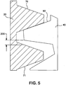
- the hysteresis inherent in the drive train will be introduced into the system once again. An example of such hysteresis can be seen with respect to Fig. 5 . As shown in Fig.
- hysteresis brake 50 ensures positive engagement of each mechanical junction of any drive train components as long as the motor is turned in the same direction. Further, positive engagement in one direction ensures that when motor direction is reversed, the distance motor turns before positive engagement returns is repeatable.
- This repeatable, predictable distance referred to herein as the "error margin,” can be calculated through calibration of the machinery to determine the distance the motor must rotate before positive engagement is reinstated. Further, the error margin can be calibrated and compensated through a software program or other means. Since the error margin is predictable after it has been calculated, the computer program can instruct the motor driver to rotate the motor the distance related to the error margin when the direction of the drive train is reversed.
- the motor may be rotated a distance sufficient to drive driven component a requested distance of travel when the drive train components are in positive engagement.
- Fig. 6 is a flow chart delineating one embodiment of a method for compensating for the predictable error margin in moving gear rack 20 in relation to carriage assembly 30.
- the error margin (or total hysteresis) is first calibrated, either manually or through the use of software, as noted by reference numeral 100.
- This error margin reflects the amount of hysteresis between positive engagement of the drive train in one direction and positive engagement of the drive train in the opposite direction.
- the software calculates the amount of motor rotation required in order to switch from a condition of positive engagement of the drive train in one direction and positive engagement of the drive train in the opposite direction (i.e., the amount of motor rotation required before the gear rack 20 is moved when the drive train switches directions). Once the error margin is calculated, the system is ready for normal operation and is operable to allow for compensation of the error margin upon reversal of direction.
- the software receives some input from the user of the system for the drive train to move a driven component (e.g., the gear rack and associated pipette) a requested direction of travel and distance of travel.
- a driven component e.g., the gear rack and associated pipette
- the system determines if the requested direction is the same as the previous direction of travel of the drive train. If the requested direction is the same direction as the previous direction, each turn of the motor results in the movement of gear rack 20 a given distance in relation to carriage assembly 30, as noted by reference numeral 108.
- the software will compensate for the error margin by turning the motor in the new direction the calibrated number of turns necessary for positive engagement in the new direction. Additionally, the program will calculate and execute the number of turns the motor must make in the new direction to move gear rack 20 the distance requested in relation to carriage assembly 30. Thereafter, as indicated by reference numeral 110 the software resets the previous direction indicator to equal the most recently requested direction of travel. Finally, as indicated by reference numeral 112, the program stops the motor and awaits further instruction on a desired direction of travel and distance of travel.
- a pipette system with a hysteresis compensation mechanism includes eight pipette drive assemblies 10 ganged together in a vertical position.
- Each pipette drive assembly includes a carriage assembly 30 fixed in position vertically and operably joined to a gear rack 20 such that the gear racks 20 may be moved vertically with respect to the carriage assemblies 30.
- the gear racks 20 and associated carriage assemblies 30 are arranged in two separate rows, with the gear racks on the first row rotated 180° from the gear racks on the second row.
- a horizontal rack assembly 100 is operable to move the ganged pipette drive assemblies 10 in the horizontal plane.
- each gear rack assembly 20 Attached to the bottom of each gear rack assembly 20 is a pipette connector 110, designed for attachment to pipette tips and operable to pipette liquids.
- Each carriage assembly has an associated drive motor positioned upon the horizontal rack assembly.
- An elongated drive shaft 120 extends from each drive motor.
- Each elongated drive shaft 120 engages the drive gear assembly 40 on one of the carriages and extends through the pass-thru holes 43 of the other carriages in the row.
- rotation of the drive gears 41 results in linear movement of gear racks 20 either upward or downward.
- each gear rack 20 and associated carriage assembly 30 is connected to a different motor and drive shaft 120, each gear rack 20 and the pipette connected thereto may be moved independent of the other gear racks and pipettes.
- a hysteresis brake as described above could be used in conjunction with a drive gear engaging another circular gear to prevent play and backlash.
- gear rack 20 could be held stationary while carriage assembly 30 moves along gear rack 20.
- Other embodiments of drive mechanisms engaging a rack are further possible.
- rubber wheels could be used in place of gears.
- means for resisting movement could comprise springs, elastic bands or rubber bands to resist movement of components and ensure positive engagement.
- any number of different pipette systems may be used with the Hysteresis Compensation System.
- the system shown in Fig. 7 could include gear racks that are 180° opposed to the gear racks shown.
- any number of gear racks and associated pipettes could be used in any one system.
- the present invention is not limited to liquid handling systems, but may be used for any number of other automated laboratory devices where a motor and a drive train is used to automatically advance a driven component.
Landscapes
- Engineering & Computer Science (AREA)
- General Engineering & Computer Science (AREA)
- Biochemistry (AREA)
- General Health & Medical Sciences (AREA)
- Health & Medical Sciences (AREA)
- Life Sciences & Earth Sciences (AREA)
- Chemical & Material Sciences (AREA)
- Analytical Chemistry (AREA)
- Mechanical Engineering (AREA)
- Physics & Mathematics (AREA)
- General Physics & Mathematics (AREA)
- Immunology (AREA)
- Pathology (AREA)
- Devices For Use In Laboratory Experiments (AREA)
- Automatic Analysis And Handling Materials Therefor (AREA)
- Sampling And Sample Adjustment (AREA)
- Transmission Devices (AREA)
Applications Claiming Priority (2)
| Application Number | Priority Date | Filing Date | Title |
|---|---|---|---|
| US10/832,663 US7534395B2 (en) | 2004-04-27 | 2004-04-27 | Hysteresis compensation system |
| PCT/US2005/009827 WO2005108951A2 (en) | 2004-04-27 | 2005-03-23 | Hysteresis compensation system |
Publications (3)
| Publication Number | Publication Date |
|---|---|
| EP1740923A2 EP1740923A2 (en) | 2007-01-10 |
| EP1740923A4 EP1740923A4 (en) | 2011-01-05 |
| EP1740923B1 true EP1740923B1 (en) | 2018-12-12 |
Family
ID=35136644
Family Applications (1)
| Application Number | Title | Priority Date | Filing Date |
|---|---|---|---|
| EP05729181.7A Expired - Lifetime EP1740923B1 (en) | 2004-04-27 | 2005-03-23 | Hysteresis compensation system |
Country Status (4)
| Country | Link |
|---|---|
| US (1) | US7534395B2 (https=) |
| EP (1) | EP1740923B1 (https=) |
| JP (1) | JP5122947B2 (https=) |
| WO (1) | WO2005108951A2 (https=) |
Families Citing this family (13)
| Publication number | Priority date | Publication date | Assignee | Title |
|---|---|---|---|---|
| DE10147684A1 (de) * | 2001-09-27 | 2003-04-24 | Oce Printing Systems Gmbh | Verfahren zum Ausgleich eines Getriebespiels bei Reversierbetrieb und Vorrichtung zur Durchführung dieses Verfahrens |
| US9103782B2 (en) | 2008-12-02 | 2015-08-11 | Malvern Instruments Incorporated | Automatic isothermal titration microcalorimeter apparatus and method of use |
| DE102012211207A1 (de) | 2012-06-28 | 2014-01-02 | Hamilton Bonaduz Ag | Pipettiervorrichtung mit Hysteresebremse |
| CN103922261B (zh) * | 2013-01-15 | 2016-08-31 | 常州金麦格生物技术有限公司 | 移液装置和使用该装置的全自动工作站及其用途 |
| CN103922262B (zh) * | 2013-01-15 | 2016-10-26 | 常州金麦格生物技术有限公司 | 移液机构和使用该机构的全自动工作站 |
| DE102013220427A1 (de) * | 2013-10-10 | 2015-04-16 | Hamilton Bonaduz Ag | Bewegungsvorrichtung mit kombiniertem Individual- und Blockbewegungsantrieb für mehrere gemeinsam geführte Bewegungseinheiten |
| DE202016105970U1 (de) * | 2016-10-24 | 2016-11-10 | Lock Antriebstechnik Gmbh | Getriebevorrichtung zur Anbringung an einer Antriebswelle |
| US11471879B2 (en) | 2019-01-04 | 2022-10-18 | Funai Electric Co., Ltd. | Volume data representation and processing for liquid dispensing devices |
| US11331660B2 (en) * | 2019-01-04 | 2022-05-17 | Funai Electric Co. Ltd. | Digital dispense system |
| US11474007B2 (en) | 2019-01-04 | 2022-10-18 | Funai Electric Co., Ltd. | Digital dispense system |
| US11768215B2 (en) | 2019-01-04 | 2023-09-26 | Funai Electric Co., Ltd. | Digital dispense system cartridge |
| WO2021258022A1 (en) * | 2020-06-19 | 2021-12-23 | Lutron Technology Company Llc | Motor magnetic brake |
| LU102878B1 (en) * | 2021-11-15 | 2023-05-15 | Stratec Se | Pipetting unit |
Citations (2)
| Publication number | Priority date | Publication date | Assignee | Title |
|---|---|---|---|---|
| US5007498A (en) * | 1988-09-06 | 1991-04-16 | Viscodrive Gmbh | Driving assembly |
| US5238095A (en) * | 1992-06-30 | 1993-08-24 | Pedu Jeffrey C | Hysteresis brakes and clutches |
Family Cites Families (40)
| Publication number | Priority date | Publication date | Assignee | Title |
|---|---|---|---|---|
| GB1041793A (en) * | 1962-05-29 | 1966-09-07 | Asquith Ltd William | Improvements in rack and pinion mechanisms |
| US3146620A (en) * | 1962-09-12 | 1964-09-01 | Jr Vaughan Morrill | Measuring apparatus for pipettes |
| JPS532619Y2 (https=) * | 1972-08-15 | 1978-01-23 | ||
| JPS53101785A (en) * | 1977-02-17 | 1978-09-05 | Toshiba Mach Co Ltd | Wind-up mechanism |
| US4117727A (en) * | 1977-12-12 | 1978-10-03 | Friswell David R | Bubble sensor and method |
| US4207770A (en) * | 1979-05-07 | 1980-06-17 | Gerald Grushow | Change of direction sensing mechanism |
| JPS5619430A (en) * | 1979-07-27 | 1981-02-24 | Olympus Optical Co Ltd | Dispensing unit |
| WO1981003545A1 (en) * | 1980-06-06 | 1981-12-10 | Varian Techtron Pty Ltd | Syringe drive system |
| US4478095A (en) * | 1981-03-09 | 1984-10-23 | Spectra-Physics, Inc. | Autosampler mechanism |
| JPS5847180A (ja) * | 1981-09-16 | 1983-03-18 | Japan Spectroscopic Co | 液体の吸引吐出装置の制御方法および装置 |
| CA1196458A (en) * | 1981-10-08 | 1985-11-12 | Yoshihiko Yamazaki | Injection molding machine |
| US4519258A (en) * | 1983-10-11 | 1985-05-28 | Eastman Kodak Company | Motorized pipette |
| US4539854A (en) * | 1983-10-13 | 1985-09-10 | Corning Glass Works | Friction drive for metering device |
| JP2727315B2 (ja) * | 1985-10-25 | 1998-03-11 | ファナック 株式会社 | 射出成形機の保圧制御方法 |
| US5206568A (en) * | 1986-03-26 | 1993-04-27 | Beckman Instruments, Inc. | Coordinated control of stepper motors |
| JPS63300881A (ja) * | 1987-05-30 | 1988-12-08 | ぺんてる株式会社 | ロボット等の直線駆動装置 |
| US4833384A (en) * | 1987-07-20 | 1989-05-23 | Syntex (U.S.A.) Inc. | Syringe drive assembly |
| US4938087A (en) * | 1989-05-31 | 1990-07-03 | Universal Instruments Corporation | Zero backlash positioning system for a movable linear axis |
| US5089229A (en) * | 1989-11-22 | 1992-02-18 | Vettest S.A. | Chemical analyzer |
| US5360596A (en) * | 1990-04-05 | 1994-11-01 | The Perkin-Elmer Corporation | Plunger homing mechanism for use in chromatography |
| JPH04248447A (ja) * | 1991-02-01 | 1992-09-03 | Sanyo Electric Co Ltd | 血液分析装置 |
| US5219099A (en) * | 1991-09-06 | 1993-06-15 | California Institute Of Technology | Coaxial lead screw drive syringe pump |
| US5183150A (en) * | 1991-12-13 | 1993-02-02 | Allied-Signal Inc. | Cargo drive unit with a hysteresis coupling |
| CA2067706A1 (en) * | 1992-03-12 | 1993-09-13 | John E. Duncan | Hysteresis brake and method of calibration thereof |
| US5337608A (en) * | 1992-12-18 | 1994-08-16 | Minnesota Mining And Manufacturing Company | Drive roller torque reference cartridge |
| US5792483A (en) * | 1993-04-05 | 1998-08-11 | Vickers, Inc. | Injection molding machine with an electric drive |
| LU88394A1 (fr) * | 1993-08-25 | 1995-03-01 | Ipalco Bv | Coupleur magnétique à hystérésis |
| DE4335863C1 (de) * | 1993-10-21 | 1995-02-02 | Eppendorf Geraetebau Netheler | Kolbenhubpipette |
| JP3460351B2 (ja) * | 1994-02-08 | 2003-10-27 | セイコーエプソン株式会社 | 位置検出装置及び位置検出方法 |
| US5635622A (en) * | 1995-10-27 | 1997-06-03 | Delco Electronics Corporation | Method of compensating for gauge hysteresis |
| JP3644558B2 (ja) * | 1995-11-02 | 2005-04-27 | 株式会社ハーモニック・ドライブ・システムズ | 撓み噛み合い式歯車装置のトルク検出機構 |
| JP3070488B2 (ja) * | 1996-09-12 | 2000-07-31 | 株式会社島津製作所 | オートサンプラ |
| DE19801334C2 (de) * | 1998-01-16 | 2000-05-25 | Saurer Allma Gmbh | Elektromagnetische Hysteresebremse, insbesondere als Fadenbremse für Textilmaschinen |
| JP3417845B2 (ja) * | 1998-05-29 | 2003-06-16 | ペンタックス株式会社 | レンズ移動制御装置 |
| US6347259B1 (en) * | 1999-04-01 | 2002-02-12 | Virtek Vision International Inc. | High precision positioning device and method of operating same |
| TWI248718B (en) * | 1999-09-02 | 2006-02-01 | Koninkl Philips Electronics Nv | Displacement device |
| JP2001264341A (ja) * | 2000-03-17 | 2001-09-26 | Olympus Optical Co Ltd | 液体分注装置 |
| DE10025611A1 (de) * | 2000-05-24 | 2001-11-29 | Trw Automotive Electron & Comp | Verfahren zur Steuerung des Drehmoments an der mit einem Elektromotor gekoppelten Gurtwelle eines Gurtaufrollers |
| US6962674B2 (en) * | 2001-02-28 | 2005-11-08 | Varian, Inc. | Dissolution test apparatus |
| DE10147684A1 (de) * | 2001-09-27 | 2003-04-24 | Oce Printing Systems Gmbh | Verfahren zum Ausgleich eines Getriebespiels bei Reversierbetrieb und Vorrichtung zur Durchführung dieses Verfahrens |
-
2004
- 2004-04-27 US US10/832,663 patent/US7534395B2/en not_active Expired - Lifetime
-
2005
- 2005-03-23 WO PCT/US2005/009827 patent/WO2005108951A2/en not_active Ceased
- 2005-03-23 JP JP2007510737A patent/JP5122947B2/ja not_active Expired - Lifetime
- 2005-03-23 EP EP05729181.7A patent/EP1740923B1/en not_active Expired - Lifetime
Patent Citations (2)
| Publication number | Priority date | Publication date | Assignee | Title |
|---|---|---|---|---|
| US5007498A (en) * | 1988-09-06 | 1991-04-16 | Viscodrive Gmbh | Driving assembly |
| US5238095A (en) * | 1992-06-30 | 1993-08-24 | Pedu Jeffrey C | Hysteresis brakes and clutches |
Also Published As
| Publication number | Publication date |
|---|---|
| JP2007537846A (ja) | 2007-12-27 |
| US20050238544A1 (en) | 2005-10-27 |
| EP1740923A2 (en) | 2007-01-10 |
| WO2005108951A3 (en) | 2007-11-01 |
| WO2005108951A2 (en) | 2005-11-17 |
| JP5122947B2 (ja) | 2013-01-16 |
| US7534395B2 (en) | 2009-05-19 |
| EP1740923A4 (en) | 2011-01-05 |
Similar Documents
| Publication | Publication Date | Title |
|---|---|---|
| EP1740923B1 (en) | Hysteresis compensation system | |
| EP0111565B1 (en) | Industrial robot | |
| CA1138227A (en) | Method and apparatus for positioning cars in a sample handling apparatus | |
| JP2947146B2 (ja) | オ−トサンプラ | |
| GB2098577A (en) | An operating arm unit controlled by a computer system | |
| CN111512136A (zh) | 使用动力转向系统的辅助马达根据位置确定周期生成测试周期 | |
| WO2004009300A1 (en) | Robotically manipulable tool with on-board processor | |
| US6247242B1 (en) | Mechanism for detecting position of a movable member | |
| JP2007537846A5 (https=) | ||
| CN111623981A (zh) | 变速机的检测方法及检测装置 | |
| US7343684B2 (en) | Robotic system with traction drive | |
| CN206021103U (zh) | 扭矩加载装置 | |
| US10766106B2 (en) | Drive shaft press | |
| JP2008537135A (ja) | 旋回プレートを有する反応容器支持、このタイプの支持を含む分析装置、および対応する分析方法 | |
| CN110376000A (zh) | 汽车转向系参数检测装置及方法 | |
| US10067042B2 (en) | Liquid analyzing device | |
| CN216485065U (zh) | 试纸条的阻挡机构及传输装置 | |
| JPH10122326A (ja) | アクチュエータおよび位置決め装置 | |
| CN213398606U (zh) | 一种等间距调节机构 | |
| WO2016039704A1 (en) | Train simulation system comprising switchable control unit | |
| EP3228991A2 (en) | Contactless position sensor with circuit structure for sensing the position of a pointer mounted to a movable part | |
| KR20130071916A (ko) | 리니어모터를 이용한 상용차용 쉬프트 액추에이터 부하 모사장치 | |
| WO2025140167A1 (en) | Pipettor, and self-locking type counting device thereof | |
| CN222886668U (zh) | 一种可调节间隔的叉货平台 | |
| CN114858485B (zh) | 驻车总成动态检测装置 |
Legal Events
| Date | Code | Title | Description |
|---|---|---|---|
| PUAI | Public reference made under article 153(3) epc to a published international application that has entered the european phase |
Free format text: ORIGINAL CODE: 0009012 |
|
| 17P | Request for examination filed |
Effective date: 20061026 |
|
| AK | Designated contracting states |
Kind code of ref document: A2 Designated state(s): AT BE BG CH CY CZ DE DK EE ES FI FR GB GR HU IE IS IT LI LT LU MC NL PL PT RO SE SI SK TR |
|
| AX | Request for extension of the european patent |
Extension state: AL BA HR LV MK YU |
|
| DAX | Request for extension of the european patent (deleted) | ||
| RBV | Designated contracting states (corrected) |
Designated state(s): DE FR GB |
|
| PUAK | Availability of information related to the publication of the international search report |
Free format text: ORIGINAL CODE: 0009015 |
|
| RIC1 | Information provided on ipc code assigned before grant |
Ipc: F16H 1/04 20060101AFI20071214BHEP |
|
| RAP1 | Party data changed (applicant data changed or rights of an application transferred) |
Owner name: BECKMAN COULTER, INC. |
|
| A4 | Supplementary search report drawn up and despatched |
Effective date: 20101202 |
|
| RIC1 | Information provided on ipc code assigned before grant |
Ipc: F16H 1/04 20060101AFI20071214BHEP Ipc: G01N 35/10 20060101ALI20101126BHEP |
|
| 17Q | First examination report despatched |
Effective date: 20111108 |
|
| REG | Reference to a national code |
Ref country code: DE Ref legal event code: R079 Ref document number: 602005055135 Country of ref document: DE Free format text: PREVIOUS MAIN CLASS: G01N0001000000 Ipc: F16H0019040000 |
|
| RIC1 | Information provided on ipc code assigned before grant |
Ipc: F16H 57/12 20060101ALI20170331BHEP Ipc: F16H 19/04 20060101AFI20170331BHEP Ipc: G01N 35/10 20060101ALI20170331BHEP |
|
| GRAP | Despatch of communication of intention to grant a patent |
Free format text: ORIGINAL CODE: EPIDOSNIGR1 |
|
| INTG | Intention to grant announced |
Effective date: 20180725 |
|
| GRAS | Grant fee paid |
Free format text: ORIGINAL CODE: EPIDOSNIGR3 |
|
| GRAA | (expected) grant |
Free format text: ORIGINAL CODE: 0009210 |
|
| AK | Designated contracting states |
Kind code of ref document: B1 Designated state(s): DE FR GB |
|
| REG | Reference to a national code |
Ref country code: GB Ref legal event code: FG4D |
|
| REG | Reference to a national code |
Ref country code: DE Ref legal event code: R096 Ref document number: 602005055135 Country of ref document: DE |
|
| REG | Reference to a national code |
Ref country code: DE Ref legal event code: R097 Ref document number: 602005055135 Country of ref document: DE |
|
| PLBE | No opposition filed within time limit |
Free format text: ORIGINAL CODE: 0009261 |
|
| STAA | Information on the status of an ep patent application or granted ep patent |
Free format text: STATUS: NO OPPOSITION FILED WITHIN TIME LIMIT |
|
| 26N | No opposition filed |
Effective date: 20190913 |
|
| P01 | Opt-out of the competence of the unified patent court (upc) registered |
Effective date: 20230606 |
|
| PGFP | Annual fee paid to national office [announced via postgrant information from national office to epo] |
Ref country code: DE Payment date: 20231229 Year of fee payment: 20 Ref country code: GB Payment date: 20240108 Year of fee payment: 20 |
|
| PGFP | Annual fee paid to national office [announced via postgrant information from national office to epo] |
Ref country code: FR Payment date: 20240103 Year of fee payment: 20 |
|
| REG | Reference to a national code |
Ref country code: DE Ref legal event code: R071 Ref document number: 602005055135 Country of ref document: DE |
|
| REG | Reference to a national code |
Ref country code: GB Ref legal event code: PE20 Expiry date: 20250322 |
|
| PG25 | Lapsed in a contracting state [announced via postgrant information from national office to epo] |
Ref country code: GB Free format text: LAPSE BECAUSE OF EXPIRATION OF PROTECTION Effective date: 20250322 |