EP1740486B1 - Rivet collating system including rivet holder and method of forming the same - Google Patents
Rivet collating system including rivet holder and method of forming the same Download PDFInfo
- Publication number
- EP1740486B1 EP1740486B1 EP05736157.8A EP05736157A EP1740486B1 EP 1740486 B1 EP1740486 B1 EP 1740486B1 EP 05736157 A EP05736157 A EP 05736157A EP 1740486 B1 EP1740486 B1 EP 1740486B1
- Authority
- EP
- European Patent Office
- Prior art keywords
- rivet
- heads
- plate
- apertures
- rivets
- Prior art date
- Legal status (The legal status is an assumption and is not a legal conclusion. Google has not performed a legal analysis and makes no representation as to the accuracy of the status listed.)
- Expired - Lifetime
Links
Images


Classifications
-
- B—PERFORMING OPERATIONS; TRANSPORTING
- B25—HAND TOOLS; PORTABLE POWER-DRIVEN TOOLS; MANIPULATORS
- B25C—HAND-HELD NAILING OR STAPLING TOOLS; MANUALLY OPERATED PORTABLE STAPLING TOOLS
- B25C3/00—Portable devices for holding and guiding nails; Nail dispensers
- B25C3/006—Portable devices for holding and guiding nails; Nail dispensers only for holding and guiding
- B25C3/008—Portable devices for holding and guiding nails; Nail dispensers only for holding and guiding the nail being hit by a hammer head
-
- B—PERFORMING OPERATIONS; TRANSPORTING
- B21—MECHANICAL METAL-WORKING WITHOUT ESSENTIALLY REMOVING MATERIAL; PUNCHING METAL
- B21J—FORGING; HAMMERING; PRESSING METAL; RIVETING; FORGE FURNACES
- B21J15/00—Riveting
- B21J15/10—Riveting machines
- B21J15/30—Particular elements, e.g. supports; Suspension equipment specially adapted for portable riveters
- B21J15/32—Devices for inserting or holding rivets in position with or without feeding arrangements
- B21J15/323—Devices for inserting or holding rivets in position with or without feeding arrangements using a carrier strip
-
- F—MECHANICAL ENGINEERING; LIGHTING; HEATING; WEAPONS; BLASTING
- F16—ENGINEERING ELEMENTS AND UNITS; GENERAL MEASURES FOR PRODUCING AND MAINTAINING EFFECTIVE FUNCTIONING OF MACHINES OR INSTALLATIONS; THERMAL INSULATION IN GENERAL
- F16G—BELTS, CABLES, OR ROPES, PREDOMINANTLY USED FOR DRIVING PURPOSES; CHAINS; FITTINGS PREDOMINANTLY USED THEREFOR
- F16G3/00—Belt fastenings, e.g. for conveyor belts
- F16G3/08—Belt fastenings, e.g. for conveyor belts consisting of plates and screw-bolts or rivets
-
- Y—GENERAL TAGGING OF NEW TECHNOLOGICAL DEVELOPMENTS; GENERAL TAGGING OF CROSS-SECTIONAL TECHNOLOGIES SPANNING OVER SEVERAL SECTIONS OF THE IPC; TECHNICAL SUBJECTS COVERED BY FORMER USPC CROSS-REFERENCE ART COLLECTIONS [XRACs] AND DIGESTS
- Y10—TECHNICAL SUBJECTS COVERED BY FORMER USPC
- Y10S—TECHNICAL SUBJECTS COVERED BY FORMER USPC CROSS-REFERENCE ART COLLECTIONS [XRACs] AND DIGESTS
- Y10S206/00—Special receptacle or package
- Y10S206/82—Separable, striplike plural articles
Definitions
- the invention relates to a collating system for rivets and, more particularly, a rivet holder and a method for forming the rivet holder.
- the fasteners In using mechanical conveyor belt fasteners for splicing belt ends together, one problem lies in the time it takes for these to be installed on the belt ends.
- the fasteners either of the solid-plate or hinged-loop variety, utilize attachment members such as rivets, staples or nails that extend through apertures in the upper and lower plates of the fasteners as well as through the belt carcass therebetween.
- Installation tools have been developed to assist in more rapidly driving the attachment members for connecting the belt fasteners to belt ends for splicing them together.
- One type of tool apparatus uses a guide block provided with several through bores arranged in a pattern corresponding to the pattern of apertures provided in the belt fastener plates.
- Rivets are loaded into the bores so that they are in proper aligned position relative to the belt fastener for installation. In this manner, several rivets can be simultaneously driven as by a gang driver saving installation time. Alternatively, the rivets can be individually driven with the guide block still saving time and providing accuracy as the installer does not have to manually align and hold the rivets as they are driven.
- the rivets have to be individually loaded into the guide block bores slowing installation time accordingly.
- a further complication arises because the rivets in one form include a pilot nail detachably connected at the lower ends of each of the rivets.
- the pilot nails include sharp ends for piercing the conveyor belt and leading the rivet therethrough as it is driven for application of the belt fasteners to the belt ends.
- the installer With a bucket full of loose rivet assemblies, the installer has to carefully reach into the bucket to avoid grabbing the sharp nail ends further slowing installation. Accordingly, to handle this problem in installation, applicants' assignee developed a rivet holder as shown in its U.S. Patent No. 5,244,088 , which is incorporated by reference as if reproduced in its entirety herein.
- the rivet holder disclosed in the '088 patent has a body formed of two separable portions that come together along a non-linear interface or part line, so that the inner facing surface of the body portion cooperate to form apertures in which the rivets are held.
- the apertures are located in a pattern matching that of the guide block bores and belt fasteners.
- the '088 patent rivet holder has been found to be extremely useful in reducing installation time at the belt splicing location since basically in the time it had taken to load a single rivet assembly into the guide block, the rivet holder can in substantially the same time permit multiple rivet assemblies to be loaded in the guide block.
- One shortcoming, however, with the above-described rivet holder is that it provides its body portions with a relatively complex shape especially at the inner facing surfaces extending non-linearly along the part line to form the apertures in which the rivets are held. This complexity in the parts of the rivet holder increases manufacturing costs associated therewith.
- Another shortcoming is that after the rivet holder is formed by releasably connecting the separable body portions together, the rivet assemblies still have to be inserted into the apertures formed by the releasably connected body portions in a separate manufacturing operation form the forming of the rivet holder body portions themselves. After inserting the rivet assemblies, the preformed rivet heads still remain outside of the apertures in the holder engaged against the upper surface thereof.
- a rivet collating system as defined in independent claim 1, which includes a plate body for forming rivet-retaining apertures each having a drive head associated therewith.
- the drive heads are releasably connected to the plate body via frangible portions so that the drive heads can be driven relative to the plate body pushing the rivet heads out from the apertures.
- the plate includes a substantially flat upper surface and the drive heads project upwardly above the plate upper surface for being engaged by a drive tool.
- a guide block is provided including guide bores that are aligned with the plate apertures so that the driven heads cause the rivet heads to enter the guide bores.
- the rivets be driven directly into rivet receiving apertures of a conveyor belt fastener rather than into the bores of an intermediate guide block.
- the plate has a substantially flat upper surface, and the drive heads project above the plate upper surface.
- the drive heads include an upper portion sized in interference with the associated aperture so that when the drive heads are driven to push the rivet heads out from the apertures, the drive heads will not pass through the plate body apertures.
- the drive heads are formed so that their upper surfaces are substantially level or flush with that of the remainder of the plate body.
- a rivet holder is thus provided that has a unitary plate in which rivet holding apertures are formed.
- the present rivet holder including the apertured unitary plate also avoids the necessity of forming complexly shaped facing surfaces along the interface between the body portions at which the apertures were formed.
- rivet or rivet assembly is used herein, the present invention is not so limited so that the term rivet encompasses other attachment members that could be used with conveyor belt fasteners as well, such as nails and possibly even staples.
- the plate or plate body includes webs circumferentially spaced about each aperture and underlying each rivet head to retain the heads in the apertures.
- a radially enlarged opening is formed between adjacent webs.
- the webs are provided with a controlled flexibility so that driving the rivet heads via the drive heads deforms the webs causing the flexible webs to deflect allowing the rivet heads to pass out from the plate apertures.
- the plate body has a thickness and the frangible portions and webs are substantially within the plate body thickness to provide the rivet holder with a low profile.
- a method of forming a rivet holder according to independent claim 16 including placing the rivets in the mold in which the rivet holder body is formed.
- the rivet heads are releasably captured by plastic material of the rivet holder body as in incident of the molding of the rivet holder body.
- FIGS. 1-3 a rivet collating system generally designated 10 in accordance with the present invention is depicted.
- the rivet collating system 10 includes a strip 11 of rivet holders 12 with each holder 12 including a plate body 14 in which a plurality of apertures 16 are formed in a predetermined pattern.
- the rivet holders 12 can include the illustrated five-rivet pattern of apertures 16, for matching that of rivet receiving apertures such as in a belt fastener 5 or guide block 18 of installation apparatus 19 for applying the fasteners 5 to conveyor belt 7, as shown in FIG. 4 .
- the plate body apertures 16 are configured for supporting the rivets 20 so that all of the rivets 20 can be inserted into corresponding rivet receiving apertures therefor such as in guide bores 22 in a single insertion operation as opposed to having to individually insert the rivets as when they are not collated by a rivet holder such as present rivet holder 12.
- the rivets 20 are assemblies 27 of rivets 20 and pilot nails 21 that are detachably secured at the lower ends of the rivets 20 for leading the rivets 20 through the carcass of the conveyor belt 7 to which the fasteners 5 are to be attached.
- the strips 11 can be provided with a predetermined number of holders 12, e.g., four holders 12, such as corresponding to the number of belt fasteners 5 to be applied via the installation tool 19 at a particular location along the belt end.
- the guide block 18 is preferably sized to fit over at least as many belt fasteners 5 as there are rivet holders 12 in a strip 11 so as to be able to receive each rivet holder 12 thereon. Accordingly, the strip 11 can be placed on the guide block 18 so that all rivet holders 12 are loaded on the guide block 18 in a single operation, rather than requiring each holder be individually loaded onto the guide block 18.
- the frangible bridges 23 are thinner than the plate bodies 14 to allow the strip 11 to be easily broken apart into one rivet holder 12 or two or three connected rivet holders 12, i.e., smaller strips 11, as may be required.
- the rivet holders 12 herein release the rivets 20 into the guide bores 22 via the use of drive heads 24 integrally and detachably connected to the rivet holder body 14.
- frangible portions 26 extend between the drive heads 24 and the body 14 of the rivet holder 12 interconnecting the drive heads 24 to the body 14.
- the drive heads 24 overlle rivet heads 28 in the apertures 16.
- impacting the drive heads 24 as with a hammer or mallet or even a power tool will cause the drive heads 24 to be severed from the rivet holder body 14 at the relatively small frangible portions 26 therebetween so as to push the heads 28 of the rivets 20 out from their respective apertures 16 In which they are releasably held, as shown in FIG. 11 .
- the heads 28 can also be driven downwardly by a power press tool that generates sufficient downward force on the heads 28 to sever the frangible portions 26.
- a power press tool that generates sufficient downward force on the heads 28 to sever the frangible portions 26.
- an installer need not be holding or otherwise manipulating the strip 11 or rivet holder 12 as the drive force is applied to the holder heads 24 as they are completely supported on the upper surface 18a of the guide block 18 ( FIG. 4 ) with the rivets 20 and/or pilot nails 21 extending into the bores thereof.
- the drive heads 24 connected to the plate body 14 by the frangible portion 26 also substantially prevent the rivets 20 from being pushed out upwardly from the apertures 16.
- the rivet assemblies 27 can each include a guide member 29 to keep the assemblies properly aligned In the bores 22 after released from their holders 12 for subsequently being driven through the plate fasteners apertures.
- the guide members can be In the form of annular washers 29 having an outer diameter slightly less than the diameter of the bores 22 so as to minimize skewing of the assemblies 27 as they are driven through and out from the bores 22.
- the rivets 20 stay substantially aligned with the central axis of the bores 22 as the assemblies 27 are driven through the guide block bores 22, so that the rivets 20 properly travel through the aligned apertures in the plates of the belt fastener 5 below the guide block 18.
- the washers 29 are preferably located toward the free end of the nails 21 as shown, e.g., up approximately 0.3 cm (1/8 inch) from the nail end 21a. This location provides the maximum distance between the rivet heads 28, which also serve to keep the assemblies 27 from skewing in the bores 22, and the guide washers 29.
- the inner diameter of the washer 29 is sized so that the washer 29 is frictionally held on the shank of the nail 21. As the nail 21 is driven through the upper plate aperture of the belt fastener 5, the washers 29 will engage on the fastener upper plate and slide along the nail 21 until the bottom end 20a of the rivet 20 impacts the washer 29 causing it to break and fall off the rivet assemblies 27.
- Another washer could be provided along the bodies of the rivets 20 below the heads 28 thereof instead of or in addition to the washer 29 on the nails 21 for additional guided support of the assemblies 27.
- the present rivet holder 12 does not require the two-piece construction as in the '088 patent rivet holder. Accordingly, it is preferred that the rivet holder plate 12 herein comprise a single piece such that the body 14 thereof is of unitary construction.
- the unitary plate body 14 is placed on the guide block 18 with its apertures 16 in alignment with the guide bores 22 so that the rivets 20 extend therein.
- the installer can release the rivet holder 12 so that it is only supported by the guide block 18 for driving the rivets 20 into the bores 22 via impacting the drive heads 24 as described earlier.
- the plate body 14 stays on top of the guide block 18 so that they are readily accessible for being discarded as opposed to creating strewn about parts on the floor around the installation site.
- the drive heads 24 are aligned with each other so that they cooperate to allow for compact stacking of rivet strips 11 against each other at the respective drive head top surfaces 24a thereof. Together, the top surfaces 24a define a single plane that provides a predetermined stacking interface 25 between rivet holder strips 11.
- the distribution of multiple drive heads 24 about the holder 12 is such that the respective drive head surfaces 24a of different holders 12 will be able to be brought into substantially secure contact with each other at the interface 25, even if the plate bodies 14 are rotated by 180° relative to each other.
- the drive head surfaces 24a are not raised, then manifestly there can be a substantially flat, single plane stacking surface provided on the rivet holders 12 with the drive heads surfaces 24a flush with the remainder of the plate body 14;
- the apertures 16 are configured so that the rivet heads 28 are supported therein.
- the apertures 16 are configured to be in interference with the rivet heads 28 held therein.
- the material of the plate body 14 in interference with the rivet heads 28 includes webs 30 of material provided about the apertures 16.
- the rivet heads 28 include a lower generally conical surface 32 that extends at least partially into the aperture 16.
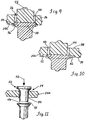
- Each aperture 16 preferably includes several arcuate webs 30 spaced circumferentially about the aperture 16 adjacent a lower surface 34 of the plate body 14 with the webs 30 being deflected slightly downward from the plate body lower surface 34 engaged along the head surface 36, as best seen in FIG. 9 .
- the inner, arcuate edges 36 of the webs 30 about each aperture 16 define an effective lower diameter of the apertures 16 that is less than the diameter of the rivet heads 28 at the point where the edges 36 are engaged therewith along the conical surfaces 32 thereof.
- the rivet holder body 14 is provided with a relatively low profile, even with the preferred upwardly projecting drive heads 24.
- the main plate body portion 14a of the rivet holder 12 from which the rivets 20 depend generally normal thereto can have a thickness that is kept to a minimum such as on the order of 0.3 cm (1/8 Inch) between the lower surface 34 and upper surface 38 thereof.
- the rivet heads 28 can be received in the apertures 16 so as not to project beyond the body portion upper surface 38, and both the small frangible portions 26 and the retaining webs 30 can be disposed substantially within the thickness of the main plate body portion 14a, less the slight downward deflection of the webs 30 from the lower surface 34, as best seen in FIGS. 9 and 11 .
- the distance from the upper surface 38 of the main plate body portion 14a to the upper surface 24a of the drive heads 24 is approximately 0.5 cm (3/16 inch).
- the frangible portions 26 and the webs 30 are vertically spaced In the apertures 16 with the frangible portions 26 being above the webs 30.
- the frangible portions 26 and the webs 30 can be in substantial alignment circumferentially about the apertures 16. Referring to FIGS. 7 and 8 , it can be seen that the frangible portions 26 extend for a much shorter extent in the circumferential direction about the aperture 16 than do the retaining webs 30. As shown, the frangible portions 26 are generally centrally circumferentially aligned with the web 30 spaced therebelow. Accordingly, the frangible portions 26 and the webs 30 provide portions of the plate body 14a that are above and generally below the rivet heads 28, respectively.
- the apertures 16 include a generally annular surface 40 extending between the plate body surfaces 34 and 38.
- the drive heads 24 have a solid cylindrical body 42 having an outer surface 44 with a diameter sized smaller than that of the aperture surface 40 and spaced therefrom via the frangible portions 26.
- the diameter of the drive head outer surface 44 can be approximately the same as that of the webs 30 at the inner edges 36 thereof.
- the frangible portions 26 engaged on the top surface 46 of the rivet heads 28 such that the rivet heads 28 are captured between the frangible portions 26 at their top surface 46 and the flexible web portions 30 at their lower surface 32.
- the bottom 48 of the drive heads 24 is preferably configured to substantially match that of the rivet head surface 46 to be in flush engagement therewith.
- the drive head surface 48 has a slight concave configuration while the rivet head surface 46 has a slight convex configuration.
- the retaining webs 30 engaged on the underside 32 of the rivet heads 28, there are portions of the main plate body 14a that are above and below the rivet heads 28 as captured in the aperture 16. More particularly, the frangible portions 26 are above the rivet heads 28, and the retaining webs 30 are generally below the rivet heads 28, and particularly the upper rivet head portion including the top surface 46 thereof residing in the apertures 16.
- the frangible portions 26 and webs 30 are generally aligned with each other circumferentially about the aperture 16, although the frangible portions 26 extend for a much smaller extent in the circumferential direction, than do the webs 30 so as to allow them to be readily severed upon application of an impact blow to the top of the drive heads 24 in the direction indicated by arrow 50 in FIG. 11 .
- the frangible portions 26 and the webs 30 are equally spaced about the aperture 16. As shown, there are three small frangible portions 26 spaced 120° from each other about the aperture 16, and there are three corresponding retaining webs 30 that from their centers are spaced approximately 120° from each other, as well.
- the flexibility of the webs 30 is controlled by providing openings 52 therebetween, as best seen in FIGS. 8 and 10 .
- the openings 52 are radially enlarged relative to the aperture 16.
- the openings 52 are recessed into the main body portion 14a of the rivet holder body 14 from the lower surface 34 thereof and radially beyond the aperture surface 40.
- the openings 52 extend in a generally circular fashion from the edges 36 of the webs 30 so that the openings 52 provide a radial enlargement of the aperture 16 between adjacent webs 30.
- the four apertures 16 adjacent to the peripheral edge 53 of the main plate body 14a will each generally include one of the recessed openings 52 that extends and opens to the edge 53 to form a vertical slot portion 52a of the opening 52 thereat, as can be seen in FIG. 6 .
- the flexibility afforded to the webs 30 can be precisely controlled. In this manner, when the drive heads 24 are driven in the downward direction 50 via an impact blow, the impact force transmitted to the rivet heads 28 will be sufficient to deflect the webs 30 so that their edges 36 are in clearance with the upper, outer periphery 54 of the rivet heads 28 to allow the rivet heads 28 to pass out of the apertures 16.
- the openings 52 are sized so that absent a relatively large force as may be applied by an impact blow to the drive heads 24, the retaining webs 30 serve to securely hold the rivet heads 28 in their apertures 16.
- the overlying drive heads 24 and frangible portions 26 substantially hold the rivet heads 28 in their apertures 16 against movement upwardly toward the upper surface 38 of the body 14 of the rivet holder 12.
- the in situ molding of the rivet heads 28 in the apertures 16 can be such that the outer periphery 54 of the heads extends beyond the aperture surface 40 to provide further holding power against inadvertent upward shifting of the rivets 20 in the apertures 16, as can be seen in FIGS. 9 and 10 . Accordingly, the rivet holders 12 herein are unlikely to have rivets 20 inadvertently released therefrom such as during transport and handling.
- the drive head body 42 is sized in clearance with the aperture 16 by the spacing provided by the frangible portions 26 therebetween. Accordingly, upon severing of the frangible portions 26 via the impact force provided to the drive heads 24 in direction 50, the drive heads 24 travel downward through the aperture 16 without encountering interference from the annular aperture surface 40, except for the flexible retaining webs 30 provided at the bottom thereof.
- the drive heads 24 are raised relative to the upper surface 38 of the plate body portion 14a, the drive heads 24 preferably are provided with an upper portion 56 that is sized to be an interference with the aperture 16, and specifically the annular surface 40 thereof.
- the upper portion 56 is an enlarged annular flange 58 formed at the upper end of the drive head cylindrical body 42.
- the enlarged flange 58 is flared upwardly and outwardly from the drive head body 42 so as to form a recess 60 about which the flange 58 extends.
- the flanges 58 all terminate at the same level so as to form the aligned top surfaces 24a of the drive heads 24 which cooperate to form a planar stacking interface 25 for compact stacking of adjacent strips 11 together.
- the annular configuration for the drive head surfaces 24a provides stability when strips 11 are stacked with the drive heads 24 engaging each other. More specifically, for stacking a set 62 or pair of rivet holder strips 11 can be arranged as shown in FIG. 12 with the respective plate bodies 14a rotated 180° relative to each other as shown. In this orientation, the rivet assemblies 27 of the holders 12 in the strips 11 facing each other extend toward each other so as to fit in gaps 64 between the five rivet assemblies 27 carried by each of the holders 12. Sets 62 can then be completely stacked in a shipping container or box in the orientation shown in FIG. 13 (one complete set 62 shown).
- the adjacent strips 11 are arranged so that they are securely engaged along stacking interface 25 therebetween.
- the rivet holder bodies 14 of adjacent strips 11 are arranged in the same orientation so that the axes 24b of the engaging drive heads 24 are aligned.
- the drive heads 24 can stay securely engaged with each other at the stacking interface 25 since the heads 24 are provided with an annular configuration at their top surface 24a via the annular flange 56 thereof. In this manner, highly unstable and difficult to achieve point or line contact between the engaging heads 24 is avoided. Further, even if the heads 24 do not engage when the respective plate holder bodies 14 are rotated about the axes 24b relative to each other such as may occur in other rivet patterns that can be implemented with the holders 12 herein, they will have the flat upper surface 38 of the plate holders 14 at which they can be securely engaged. Manifestly, where the drive heads 24 are not raised relative to the plate bodies 14, the plate bodies 14 in stacked strips 11 can be securely engaged against each other along the substantially flat upper surfaces 38 thereof. Accordingly, the present rivet holders 12 allow compact stacking thereof along a planar stacking interface 25 so that plate bodies 14 in a strip 11 stay substantially in parallel orientation relative to the bodies 14 in another strip 11 stacked securely thereagainst.
- manufacture of the rivet holders 12 herein also can be done more efficiently than that of the prior two-piece pivotal rivet holder as the rivets 20, and specifically the rivet heads 28 thereof, are captured in the apertures 16 of the rivet holder 12 as the rivet holder 12 is molded.
- the rivets 20 can be manually inserted into the mold for the rivet holder 12 at the locations where the apertures 16 are to be formed.
- this pre-molding step of rivet insertion in the mold can be automated. Thereafter, the molding operation begins with the mold closed and plastic material injected into the mold to form the plate body 14.
- the mold is opened and completely formed rivet holder strips 11 are removed with the rivets 20 captured by the respective rivet holders 12 thereof so as to be in final assembly therewith. In this manner, there are no post-molding manufacturing operations that need to take place in terms of assembling the rivets 20 to the rivet holders 12 as in the prior two-piece rivet holders.
- the rivet holders 12 or holder strips 11 can be molded with plastic material provided with a coloring agent. Different colored strips 11 can be provided, which can vary based on the number and size of rivets 20 supported by the holders 12 in the strip 11. In this regard, the molded rivet holders 12 are well-suited for being color-coded to differentiate one type of holder 12 from another.
Landscapes
- Engineering & Computer Science (AREA)
- Mechanical Engineering (AREA)
- General Engineering & Computer Science (AREA)
- Insertion Pins And Rivets (AREA)
- Connection Of Plates (AREA)
Priority Applications (1)
| Application Number | Priority Date | Filing Date | Title |
|---|---|---|---|
| PL05736157T PL1740486T3 (pl) | 2004-04-14 | 2005-04-11 | System rozmieszczający nity zawierający uchwyt do nitów i sposób jego wytwarzania |
Applications Claiming Priority (2)
| Application Number | Priority Date | Filing Date | Title |
|---|---|---|---|
| US10/823,878 US7654389B2 (en) | 2004-04-14 | 2004-04-14 | Rivet collating system including rivet holder and method of forming the same |
| PCT/US2005/012119 WO2005105614A2 (en) | 2004-04-14 | 2005-04-11 | Rivet collating system including rivet holder and method of forming the same |
Publications (3)
| Publication Number | Publication Date |
|---|---|
| EP1740486A2 EP1740486A2 (en) | 2007-01-10 |
| EP1740486A4 EP1740486A4 (en) | 2014-01-08 |
| EP1740486B1 true EP1740486B1 (en) | 2017-11-29 |
Family
ID=35095172
Family Applications (1)
| Application Number | Title | Priority Date | Filing Date |
|---|---|---|---|
| EP05736157.8A Expired - Lifetime EP1740486B1 (en) | 2004-04-14 | 2005-04-11 | Rivet collating system including rivet holder and method of forming the same |
Country Status (8)
| Country | Link |
|---|---|
| US (1) | US7654389B2 (pl) |
| EP (1) | EP1740486B1 (pl) |
| AU (1) | AU2005237976B2 (pl) |
| CA (3) | CA2986332C (pl) |
| PL (1) | PL1740486T3 (pl) |
| TR (1) | TR201802731T4 (pl) |
| WO (1) | WO2005105614A2 (pl) |
| ZA (1) | ZA200608782B (pl) |
Families Citing this family (12)
| Publication number | Priority date | Publication date | Assignee | Title |
|---|---|---|---|---|
| US8151432B2 (en) * | 2008-03-10 | 2012-04-10 | Flexible Steel Lacing Company | Conveyor belt splicing system and method |
| US8403139B2 (en) | 2011-03-10 | 2013-03-26 | Conveyor Accessories, Inc. | Apparatus and system for retaining and installing rivets |
| US9422962B1 (en) * | 2011-06-23 | 2016-08-23 | Anthony C. Binek | Collated staple strip assembly |
| WO2013016170A1 (en) * | 2011-07-22 | 2013-01-31 | Gripnail Corporation | Insulation hanger strips and safety stack packaging therefor |
| US9309911B1 (en) * | 2012-01-23 | 2016-04-12 | K & R Industries Inc. | Cap nail |
| DE102012208042A1 (de) * | 2012-05-14 | 2013-11-14 | Airbus Operations Gmbh | Vorrichtung und Verfahren zum Stecken eines Befestigungsmittelverbundes |
| USD747942S1 (en) * | 2013-10-11 | 2016-01-26 | Flexible Steel Lacing Company | Multiple rivet driver for a power tool |
| US10228043B2 (en) | 2014-03-28 | 2019-03-12 | Flexible Steel Lacing Company | Hydraulic vibratory tool for driving rivets of conveyor belt fasteners |
| WO2016089881A1 (en) * | 2014-12-02 | 2016-06-09 | Flexible Steel Lacing Company | Collating system for conveyor belt rivets and method |
| US10105751B2 (en) | 2015-12-10 | 2018-10-23 | Honeywell Federal Manufacturing & Technologies, Llc | Rivet dispenser and method for loading rivets into handheld rivet gun |
| US11542709B2 (en) * | 2020-01-06 | 2023-01-03 | Jd Russell Company | Protective cap for reinforcement bars |
| CN112059095B (zh) * | 2020-07-30 | 2022-06-03 | 广东长盈精密技术有限公司 | 自动铆压设备 |
Family Cites Families (37)
| Publication number | Priority date | Publication date | Assignee | Title |
|---|---|---|---|---|
| US1263218A (en) * | 1916-12-12 | 1918-04-16 | Albert C Fischer | Combined nail holding and spacing means. |
| US1747390A (en) * | 1927-03-03 | 1930-02-18 | John F Robb | Partition maker |
| US3303632A (en) * | 1964-08-03 | 1967-02-14 | Neal M White | Nail packaging device |
| US3432985A (en) * | 1965-10-04 | 1969-03-18 | Donald B Halstead | Strip packaging machine for nails and other similar articles |
| US3450255A (en) * | 1968-03-08 | 1969-06-17 | Fastener Corp | Bundle or package of fasteners |
| DE2022136B1 (de) * | 1970-05-06 | 1971-08-26 | Reich Maschf Gmbh Karl | Haltegurt fuer Befestigungsmittel und Verfahren zum Herstellen des Haltegurtes |
| DE2042769C3 (de) * | 1970-08-28 | 1981-01-29 | Hilti Ag, Schaan (Liechtenstein) | Mit Nägeln bestücktes Magazin für ein pulverkraftbetriebenes Setzgerät |
| DE2042768C3 (de) * | 1970-08-28 | 1981-01-29 | Hilti Ag, Schaan (Liechtenstein) | Mit Nägeln bestücktes Magazin für ein pulverkraftbetriebenes Setzgerät |
| DE2350433C2 (de) * | 1970-08-28 | 1982-07-08 | Hilti AG, 9494 Schaan | Mit Nägeln bestücktes Magazin für ein pulverkraftbetriebenes Setzgerät |
| US3679266A (en) * | 1970-12-17 | 1972-07-25 | Robert C Jenkins | Lug template |
| DE2211511A1 (de) * | 1972-03-10 | 1973-09-20 | Dieter Haubold Ind Nagelgeraet | Magazinstreifen fuer ein geraet zum eintreiben von ziernaegeln |
| DE7344665U (de) * | 1973-12-17 | 1974-03-14 | Hilti Ag | Magazin für pulverkraftbetriebene Setzgeräte |
| US4018334A (en) * | 1973-03-09 | 1977-04-19 | Bulten-Kanthal Aktiebolag | Fastener package |
| SE387915B (sv) * | 1973-04-05 | 1976-09-20 | Nordisk Kartro Ab | Festorgansforpackning |
| US3990343A (en) * | 1973-06-05 | 1976-11-09 | Uniroyal Inc. | Rivets for securing end connectors to conveyor belts |
| US3885669A (en) * | 1974-04-29 | 1975-05-27 | Duo Fast Corp | Rotary entry fastener carrier and strip |
| US3913180A (en) * | 1974-06-10 | 1975-10-21 | Flexible Steel Lacing Co | Riveting system and nail and rivet assembly therefor |
| US4033456A (en) * | 1976-05-25 | 1977-07-05 | Amp Incorporated | Terminal strip having plastic carrier strip |
| DE2659150C3 (de) * | 1976-12-28 | 1981-10-29 | Schmale GmbH & Co KG, 5880 Lüdenscheid | Mit Beschlägen versehener Leitstreifen für eine Anschlagmaschine |
| US4684022A (en) * | 1977-10-25 | 1987-08-04 | Duo-Fast Corporation | Fastener strip |
| US4218953A (en) * | 1978-03-21 | 1980-08-26 | Haytayan Harry M | Self-piercing pop rivet fasteners |
| US4333217A (en) * | 1978-09-01 | 1982-06-08 | Flexible Steel Lacing Company | Apparatus for stapling belt |
| US4258461A (en) * | 1978-10-05 | 1981-03-31 | Flexible Steel Lacing Company | Apparatus for applying belt fasteners to a belt |
| US4380109A (en) * | 1978-10-05 | 1983-04-19 | Flexible Steel Lacing Company | Method for applying belt fasteners to a belt |
| US4344213A (en) * | 1978-10-05 | 1982-08-17 | Flexible Steel Lacing Company | Rivet guiding apparatus |
| US4212094A (en) * | 1978-10-05 | 1980-07-15 | Flexible Steel Lacing Company | Belt fasteners |
| DE2907486C2 (de) * | 1979-02-26 | 1985-05-23 | SFS Stadler AG, Heerbrugg | Aus einem Kunststoffband geformter Magazinierstreifen für bolzenförmige Befestigungselemente |
| DE3332927C1 (de) | 1983-09-13 | 1985-04-11 | Mato Maschinen- Und Metallwarenfabrik Curt Matthaei Gmbh & Co Kg, 6050 Offenbach | Plattenverbinder fuer die Enden von Foerderbandgurten |
| DD230826A1 (de) | 1984-03-05 | 1985-12-11 | Univ Dresden Tech | Verfahren und extrusionsvorrichtung zur formung fliessfaehiger massen |
| US4718551A (en) * | 1986-10-17 | 1988-01-12 | Erico International Corporation | Collation strip |
| DE3917846A1 (de) * | 1989-06-01 | 1990-12-06 | Hilti Ag | Traegerstreifen fuer pulverkraftbetriebene setzgeraete |
| EP0565302A2 (en) * | 1992-04-08 | 1993-10-13 | Ariel Industries Plc | Fastener carrier tape |
| US5244088A (en) * | 1992-04-16 | 1993-09-14 | Flexible Steel Lacing Company | Snap apart rivet holder |
| AU7805094A (en) * | 1993-10-01 | 1995-05-01 | Henrob Ltd | Carrier tape for fasteners |
| US5366082A (en) * | 1994-01-25 | 1994-11-22 | Haytayan Harry M | Nail support strips |
| US6823990B2 (en) * | 2000-08-21 | 2004-11-30 | Power Products Iii, Llc | Nail holder strip |
| US7007349B2 (en) * | 2002-03-04 | 2006-03-07 | Flexible Steel Lacing Company | Conveyor belt fasteners |
-
2004
- 2004-04-14 US US10/823,878 patent/US7654389B2/en not_active Expired - Lifetime
-
2005
- 2005-04-11 AU AU2005237976A patent/AU2005237976B2/en not_active Expired
- 2005-04-11 EP EP05736157.8A patent/EP1740486B1/en not_active Expired - Lifetime
- 2005-04-11 WO PCT/US2005/012119 patent/WO2005105614A2/en not_active Ceased
- 2005-04-11 TR TR2018/02731T patent/TR201802731T4/tr unknown
- 2005-04-11 CA CA2986332A patent/CA2986332C/en not_active Expired - Lifetime
- 2005-04-11 CA CA2563113A patent/CA2563113C/en not_active Expired - Lifetime
- 2005-04-11 CA CA2855750A patent/CA2855750C/en not_active Expired - Lifetime
- 2005-04-11 PL PL05736157T patent/PL1740486T3/pl unknown
-
2006
- 2006-10-20 ZA ZA200608782A patent/ZA200608782B/xx unknown
Non-Patent Citations (1)
| Title |
|---|
| None * |
Also Published As
| Publication number | Publication date |
|---|---|
| CA2563113C (en) | 2014-07-29 |
| CA2986332C (en) | 2019-04-09 |
| CA2855750A1 (en) | 2005-11-10 |
| EP1740486A2 (en) | 2007-01-10 |
| AU2005237976B2 (en) | 2012-03-01 |
| US7654389B2 (en) | 2010-02-02 |
| CA2855750C (en) | 2018-01-09 |
| TR201802731T4 (tr) | 2018-03-21 |
| EP1740486A4 (en) | 2014-01-08 |
| CA2986332A1 (en) | 2005-11-10 |
| ZA200608782B (en) | 2008-08-27 |
| PL1740486T3 (pl) | 2018-06-29 |
| CA2563113A1 (en) | 2005-11-10 |
| WO2005105614A2 (en) | 2005-11-10 |
| US20050230278A1 (en) | 2005-10-20 |
| AU2005237976A1 (en) | 2005-11-10 |
| WO2005105614A3 (en) | 2006-09-28 |
Similar Documents
| Publication | Publication Date | Title |
|---|---|---|
| EP1740486B1 (en) | Rivet collating system including rivet holder and method of forming the same | |
| US8403139B2 (en) | Apparatus and system for retaining and installing rivets | |
| US4218953A (en) | Self-piercing pop rivet fasteners | |
| US6789593B1 (en) | Hole puncher and reinforcer | |
| US12162669B2 (en) | Collating system for conveyor belt rivets and method | |
| EP0529690B1 (en) | Stackable washer | |
| AU656068B2 (en) | Snap apart rivet holder | |
| US20140348620A1 (en) | Method of handling clamshell containers containing a particulate aliquot | |
| AU2012202542B2 (en) | Rivet collating system including rivet holder and method of forming the same | |
| US6769339B2 (en) | Die set pin retainer | |
| EP2167388B1 (en) | Method of handling clamshell containers containing a particulate aliquot | |
| US4657422A (en) | Binder | |
| US5419035A (en) | Snap attaching tool | |
| CA1271462A (en) | Desk clamping device or decollator for tearing off strip side edges | |
| WO2006031228A1 (en) | Hole puncher and reinforcer | |
| CA2860148A1 (en) | Method of handling clamshell containers containing a particulate aliquot |
Legal Events
| Date | Code | Title | Description |
|---|---|---|---|
| PUAI | Public reference made under article 153(3) epc to a published international application that has entered the european phase |
Free format text: ORIGINAL CODE: 0009012 |
|
| 17P | Request for examination filed |
Effective date: 20061107 |
|
| AK | Designated contracting states |
Kind code of ref document: A2 Designated state(s): AT BE BG CH CY CZ DE DK EE ES FI FR GB GR HU IE IS IT LI LT LU MC NL PL PT RO SE SI SK TR |
|
| AX | Request for extension of the european patent |
Extension state: AL BA HR LV MK YU |
|
| DAX | Request for extension of the european patent (deleted) | ||
| A4 | Supplementary search report drawn up and despatched |
Effective date: 20131205 |
|
| RIC1 | Information provided on ipc code assigned before grant |
Ipc: B65D 85/24 20060101AFI20131129BHEP Ipc: B21J 15/32 20060101ALI20131129BHEP |
|
| 17Q | First examination report despatched |
Effective date: 20140415 |
|
| GRAP | Despatch of communication of intention to grant a patent |
Free format text: ORIGINAL CODE: EPIDOSNIGR1 |
|
| INTG | Intention to grant announced |
Effective date: 20170616 |
|
| GRAS | Grant fee paid |
Free format text: ORIGINAL CODE: EPIDOSNIGR3 |
|
| GRAA | (expected) grant |
Free format text: ORIGINAL CODE: 0009210 |
|
| AK | Designated contracting states |
Kind code of ref document: B1 Designated state(s): AT BE BG CH CY CZ DE DK EE ES FI FR GB GR HU IE IS IT LI LT LU MC NL PL PT RO SE SI SK TR |
|
| REG | Reference to a national code |
Ref country code: GB Ref legal event code: FG4D |
|
| REG | Reference to a national code |
Ref country code: CH Ref legal event code: EP |
|
| REG | Reference to a national code |
Ref country code: AT Ref legal event code: REF Ref document number: 950163 Country of ref document: AT Kind code of ref document: T Effective date: 20171215 |
|
| REG | Reference to a national code |
Ref country code: IE Ref legal event code: FG4D |
|
| REG | Reference to a national code |
Ref country code: DE Ref legal event code: R096 Ref document number: 602005053149 Country of ref document: DE |
|
| REG | Reference to a national code |
Ref country code: NL Ref legal event code: MP Effective date: 20171129 |
|
| REG | Reference to a national code |
Ref country code: LT Ref legal event code: MG4D |
|
| REG | Reference to a national code |
Ref country code: AT Ref legal event code: MK05 Ref document number: 950163 Country of ref document: AT Kind code of ref document: T Effective date: 20171129 |
|
| REG | Reference to a national code |
Ref country code: FR Ref legal event code: PLFP Year of fee payment: 14 |
|
| PG25 | Lapsed in a contracting state [announced via postgrant information from national office to epo] |
Ref country code: ES Free format text: LAPSE BECAUSE OF FAILURE TO SUBMIT A TRANSLATION OF THE DESCRIPTION OR TO PAY THE FEE WITHIN THE PRESCRIBED TIME-LIMIT Effective date: 20171129 Ref country code: FI Free format text: LAPSE BECAUSE OF FAILURE TO SUBMIT A TRANSLATION OF THE DESCRIPTION OR TO PAY THE FEE WITHIN THE PRESCRIBED TIME-LIMIT Effective date: 20171129 Ref country code: LT Free format text: LAPSE BECAUSE OF FAILURE TO SUBMIT A TRANSLATION OF THE DESCRIPTION OR TO PAY THE FEE WITHIN THE PRESCRIBED TIME-LIMIT Effective date: 20171129 Ref country code: SE Free format text: LAPSE BECAUSE OF FAILURE TO SUBMIT A TRANSLATION OF THE DESCRIPTION OR TO PAY THE FEE WITHIN THE PRESCRIBED TIME-LIMIT Effective date: 20171129 |
|
| PG25 | Lapsed in a contracting state [announced via postgrant information from national office to epo] |
Ref country code: BG Free format text: LAPSE BECAUSE OF FAILURE TO SUBMIT A TRANSLATION OF THE DESCRIPTION OR TO PAY THE FEE WITHIN THE PRESCRIBED TIME-LIMIT Effective date: 20180228 Ref country code: AT Free format text: LAPSE BECAUSE OF FAILURE TO SUBMIT A TRANSLATION OF THE DESCRIPTION OR TO PAY THE FEE WITHIN THE PRESCRIBED TIME-LIMIT Effective date: 20171129 Ref country code: GR Free format text: LAPSE BECAUSE OF FAILURE TO SUBMIT A TRANSLATION OF THE DESCRIPTION OR TO PAY THE FEE WITHIN THE PRESCRIBED TIME-LIMIT Effective date: 20180301 |
|
| PG25 | Lapsed in a contracting state [announced via postgrant information from national office to epo] |
Ref country code: NL Free format text: LAPSE BECAUSE OF FAILURE TO SUBMIT A TRANSLATION OF THE DESCRIPTION OR TO PAY THE FEE WITHIN THE PRESCRIBED TIME-LIMIT Effective date: 20171129 |
|
| PG25 | Lapsed in a contracting state [announced via postgrant information from national office to epo] |
Ref country code: SK Free format text: LAPSE BECAUSE OF FAILURE TO SUBMIT A TRANSLATION OF THE DESCRIPTION OR TO PAY THE FEE WITHIN THE PRESCRIBED TIME-LIMIT Effective date: 20171129 Ref country code: EE Free format text: LAPSE BECAUSE OF FAILURE TO SUBMIT A TRANSLATION OF THE DESCRIPTION OR TO PAY THE FEE WITHIN THE PRESCRIBED TIME-LIMIT Effective date: 20171129 Ref country code: CY Free format text: LAPSE BECAUSE OF FAILURE TO SUBMIT A TRANSLATION OF THE DESCRIPTION OR TO PAY THE FEE WITHIN THE PRESCRIBED TIME-LIMIT Effective date: 20171129 Ref country code: DK Free format text: LAPSE BECAUSE OF FAILURE TO SUBMIT A TRANSLATION OF THE DESCRIPTION OR TO PAY THE FEE WITHIN THE PRESCRIBED TIME-LIMIT Effective date: 20171129 |
|
| REG | Reference to a national code |
Ref country code: DE Ref legal event code: R097 Ref document number: 602005053149 Country of ref document: DE |
|
| PG25 | Lapsed in a contracting state [announced via postgrant information from national office to epo] |
Ref country code: RO Free format text: LAPSE BECAUSE OF FAILURE TO SUBMIT A TRANSLATION OF THE DESCRIPTION OR TO PAY THE FEE WITHIN THE PRESCRIBED TIME-LIMIT Effective date: 20171129 Ref country code: IT Free format text: LAPSE BECAUSE OF FAILURE TO SUBMIT A TRANSLATION OF THE DESCRIPTION OR TO PAY THE FEE WITHIN THE PRESCRIBED TIME-LIMIT Effective date: 20171129 |
|
| PLBE | No opposition filed within time limit |
Free format text: ORIGINAL CODE: 0009261 |
|
| STAA | Information on the status of an ep patent application or granted ep patent |
Free format text: STATUS: NO OPPOSITION FILED WITHIN TIME LIMIT |
|
| REG | Reference to a national code |
Ref country code: DE Ref legal event code: R119 Ref document number: 602005053149 Country of ref document: DE |
|
| 26N | No opposition filed |
Effective date: 20180830 |
|
| PG25 | Lapsed in a contracting state [announced via postgrant information from national office to epo] |
Ref country code: SI Free format text: LAPSE BECAUSE OF FAILURE TO SUBMIT A TRANSLATION OF THE DESCRIPTION OR TO PAY THE FEE WITHIN THE PRESCRIBED TIME-LIMIT Effective date: 20171129 Ref country code: MC Free format text: LAPSE BECAUSE OF FAILURE TO SUBMIT A TRANSLATION OF THE DESCRIPTION OR TO PAY THE FEE WITHIN THE PRESCRIBED TIME-LIMIT Effective date: 20171129 |
|
| REG | Reference to a national code |
Ref country code: CH Ref legal event code: PL |
|
| REG | Reference to a national code |
Ref country code: BE Ref legal event code: MM Effective date: 20180430 |
|
| GBPC | Gb: european patent ceased through non-payment of renewal fee |
Effective date: 20180411 |
|
| REG | Reference to a national code |
Ref country code: IE Ref legal event code: MM4A |
|
| PG25 | Lapsed in a contracting state [announced via postgrant information from national office to epo] |
Ref country code: LU Free format text: LAPSE BECAUSE OF NON-PAYMENT OF DUE FEES Effective date: 20180411 Ref country code: DE Free format text: LAPSE BECAUSE OF NON-PAYMENT OF DUE FEES Effective date: 20181101 |
|
| PG25 | Lapsed in a contracting state [announced via postgrant information from national office to epo] |
Ref country code: CH Free format text: LAPSE BECAUSE OF NON-PAYMENT OF DUE FEES Effective date: 20180430 Ref country code: LI Free format text: LAPSE BECAUSE OF NON-PAYMENT OF DUE FEES Effective date: 20180430 Ref country code: BE Free format text: LAPSE BECAUSE OF NON-PAYMENT OF DUE FEES Effective date: 20180430 Ref country code: GB Free format text: LAPSE BECAUSE OF NON-PAYMENT OF DUE FEES Effective date: 20180411 |
|
| PG25 | Lapsed in a contracting state [announced via postgrant information from national office to epo] |
Ref country code: IE Free format text: LAPSE BECAUSE OF NON-PAYMENT OF DUE FEES Effective date: 20180411 |
|
| PG25 | Lapsed in a contracting state [announced via postgrant information from national office to epo] |
Ref country code: HU Free format text: LAPSE BECAUSE OF FAILURE TO SUBMIT A TRANSLATION OF THE DESCRIPTION OR TO PAY THE FEE WITHIN THE PRESCRIBED TIME-LIMIT; INVALID AB INITIO Effective date: 20050411 Ref country code: PT Free format text: LAPSE BECAUSE OF FAILURE TO SUBMIT A TRANSLATION OF THE DESCRIPTION OR TO PAY THE FEE WITHIN THE PRESCRIBED TIME-LIMIT Effective date: 20171129 |
|
| PG25 | Lapsed in a contracting state [announced via postgrant information from national office to epo] |
Ref country code: IS Free format text: LAPSE BECAUSE OF FAILURE TO SUBMIT A TRANSLATION OF THE DESCRIPTION OR TO PAY THE FEE WITHIN THE PRESCRIBED TIME-LIMIT Effective date: 20180329 |
|
| PGFP | Annual fee paid to national office [announced via postgrant information from national office to epo] |
Ref country code: CZ Payment date: 20240322 Year of fee payment: 20 |
|
| PGFP | Annual fee paid to national office [announced via postgrant information from national office to epo] |
Ref country code: TR Payment date: 20240321 Year of fee payment: 20 Ref country code: PL Payment date: 20240320 Year of fee payment: 20 |
|
| PGFP | Annual fee paid to national office [announced via postgrant information from national office to epo] |
Ref country code: FR Payment date: 20240425 Year of fee payment: 20 |
|
| PG25 | Lapsed in a contracting state [announced via postgrant information from national office to epo] |
Ref country code: CZ Free format text: LAPSE BECAUSE OF EXPIRATION OF PROTECTION Effective date: 20250411 |