EP1740079B1 - Wiping material dispenser provided with a cutting device comprising a format selecting unit - Google Patents
Wiping material dispenser provided with a cutting device comprising a format selecting unit Download PDFInfo
- Publication number
- EP1740079B1 EP1740079B1 EP05747033A EP05747033A EP1740079B1 EP 1740079 B1 EP1740079 B1 EP 1740079B1 EP 05747033 A EP05747033 A EP 05747033A EP 05747033 A EP05747033 A EP 05747033A EP 1740079 B1 EP1740079 B1 EP 1740079B1
- Authority
- EP
- European Patent Office
- Prior art keywords
- drum
- machine
- end piece
- gear wheel
- shaped
- Prior art date
- Legal status (The legal status is an assumption and is not a legal conclusion. Google has not performed a legal analysis and makes no representation as to the accuracy of the status listed.)
- Not-in-force
Links
Images


Classifications
-
- A—HUMAN NECESSITIES
- A47—FURNITURE; DOMESTIC ARTICLES OR APPLIANCES; COFFEE MILLS; SPICE MILLS; SUCTION CLEANERS IN GENERAL
- A47K—SANITARY EQUIPMENT NOT OTHERWISE PROVIDED FOR; TOILET ACCESSORIES
- A47K10/00—Body-drying implements; Toilet paper; Holders therefor
- A47K10/24—Towel dispensers, e.g. for piled-up or folded textile towels; Toilet-paper dispensers; Dispensers for piled-up or folded textile towels provided or not with devices for taking-up soiled towels as far as not mechanically driven
- A47K10/32—Dispensers for paper towels or toilet-paper
- A47K10/34—Dispensers for paper towels or toilet-paper dispensing from a web, e.g. with mechanical dispensing means
- A47K10/36—Dispensers for paper towels or toilet-paper dispensing from a web, e.g. with mechanical dispensing means with mechanical dispensing, roll switching or cutting devices
- A47K10/3631—The cutting devices being driven manually
- A47K10/3637—The cutting devices being driven manually using a crank or handle
-
- A—HUMAN NECESSITIES
- A47—FURNITURE; DOMESTIC ARTICLES OR APPLIANCES; COFFEE MILLS; SPICE MILLS; SUCTION CLEANERS IN GENERAL
- A47K—SANITARY EQUIPMENT NOT OTHERWISE PROVIDED FOR; TOILET ACCESSORIES
- A47K10/00—Body-drying implements; Toilet paper; Holders therefor
- A47K10/24—Towel dispensers, e.g. for piled-up or folded textile towels; Toilet-paper dispensers; Dispensers for piled-up or folded textile towels provided or not with devices for taking-up soiled towels as far as not mechanically driven
- A47K10/32—Dispensers for paper towels or toilet-paper
- A47K10/34—Dispensers for paper towels or toilet-paper dispensing from a web, e.g. with mechanical dispensing means
- A47K10/36—Dispensers for paper towels or toilet-paper dispensing from a web, e.g. with mechanical dispensing means with mechanical dispensing, roll switching or cutting devices
- A47K10/3631—The cutting devices being driven manually
- A47K2010/365—Triggering mechanism for the blade
-
- Y—GENERAL TAGGING OF NEW TECHNOLOGICAL DEVELOPMENTS; GENERAL TAGGING OF CROSS-SECTIONAL TECHNOLOGIES SPANNING OVER SEVERAL SECTIONS OF THE IPC; TECHNICAL SUBJECTS COVERED BY FORMER USPC CROSS-REFERENCE ART COLLECTIONS [XRACs] AND DIGESTS
- Y10—TECHNICAL SUBJECTS COVERED BY FORMER USPC
- Y10T—TECHNICAL SUBJECTS COVERED BY FORMER US CLASSIFICATION
- Y10T83/00—Cutting
- Y10T83/465—Cutting motion of tool has component in direction of moving work
- Y10T83/4766—Orbital motion of cutting blade
- Y10T83/4795—Rotary tool
- Y10T83/4812—Compound movement of tool during tool cycle
-
- Y—GENERAL TAGGING OF NEW TECHNOLOGICAL DEVELOPMENTS; GENERAL TAGGING OF CROSS-SECTIONAL TECHNOLOGIES SPANNING OVER SEVERAL SECTIONS OF THE IPC; TECHNICAL SUBJECTS COVERED BY FORMER USPC CROSS-REFERENCE ART COLLECTIONS [XRACs] AND DIGESTS
- Y10—TECHNICAL SUBJECTS COVERED BY FORMER USPC
- Y10T—TECHNICAL SUBJECTS COVERED BY FORMER US CLASSIFICATION
- Y10T83/00—Cutting
- Y10T83/889—Tool with either work holder or means to hold work supply
- Y10T83/896—Rotatable wound package supply
Definitions
- the invention relates to the technical sector of dispensing machines with automatic cutting of wiping paper-type wiping materials for towel, toilet paper, wiping and cleaning applications in general.
- the Applicant has developed many devices of this type which comprise, in the usual manner, a housing, a hood, a drum with integrated cutting blade, said blade being able to exit the drum in operation by means of launching and recalling drum.
- Side flanges of the housing are arranged to support the coil of material that comes, either in direct support on the drum, according to the teaching of the patent FR 2,322,215 , or in a plane above the drum without contact therewith, as for example in the embodiment described in the patent FR 2.799.946 .
- a pressure roller is capable of ensuring a pressure of the web of material at a given location in addition to a second defined pressure zone towards the cutting zone of the web of material at the drum.
- the loading coil can be mounted either on the receiving drum of the cutting mechanism, or in a plane above the drum and without contact therewith.
- the apparatus comprises a base casing with a bottom face and a bottom face with a cover, said casing receiving in a detachable manner, snap-fastening, a cartridge defining a supporting structure comprising two lateral transverse flanges, a connecting plate arranged between the flanges and a front spacer bar.
- the flanges receive, in their upper part, support ends of the material reel and, in their lower part, two drums arranged side by side, with no direct contact between them, the first drum being the blade drum, the second being the return drum, said drums being arranged at one of their ends facing to receive toothed rings for their connection and their rotation relative to each other.
- the blade drum is furthermore provided with a third ring gear cooperating with the mechanism for rotating the drums including a fixed cam.
- This blade holder arm of the cutting device includes a movable blade which cooperates with the aforementioned fixed cam by defining the path of the cutting blade.
- This specific apparatus includes a template for adjusting the format of the web of material to be dispensed, either by a prior change of pinion, or with the use of a sliding pinion that can be displaced in order to cooperate according to the position with a particular toothed wheel by a Drum arrangement in particular.
- Said sliding pinion is associated with an index protruding mounted on the movable shaft support sliding pinion and to be moved beforehand by the operator. This requires a prior adjustment of the format by the operator with opening of the device.
- This apparatus has the features of the preamble of claim 1.
- the cutting device is independent of the arrangements and mechanisms for selecting the format.
- the Applicant wanted to improve the output of the cutting blade out of the drum with a smooth operation, which can be adapted to any type of dispensing machine recalled above.
- Another object of the invention has been to incorporate a format selector device complementary to said cutting device, which is of simplified construction, with a minimum of parts, and an ease of adjustment for the operator.
- the aim sought by the Applicant has thus been to make improvements on the cutting device and on the format selection device which can be integrated in an optimized manner into existing devices.
- the apparatus for dispensing wiping materials of the type comprising a casing with lateral flanges between which are arranged a receiving drum of a blade holder with a cutting blade, a reel of materials, is remarkable in that one of the transverse sides of the drum has in its extension a remote support plate having an opening for fixing the end of the blade holder, in that a toothed sector is mounted on said end with a peripheral end toothed, in that the toothed sector cooperates with a toothed wheel mounted free on the axis of the drum, said toothed wheel being secured to a hook cam, and in that the drum has, on the outer face of said transverse side, a shape protruding with a ramp profile, and in that the lateral flange of the casing opposite receiving the axis of the drum allows the attachment of a profiled body disposed between two fixed stops, said body having an elastic capacity pivoting to cooperate by its end forming appendage and head with either said hook cam, or
- the dispensing apparatus is referenced as a whole by (1) and comprises a casing (2) having side flanges (3) (4) supporting the drum (5) including a cutting device on the one hand, and the coil of material (7) on the other hand.
- the drum whose end axes (5a) are positioned in the flanges (3) (4), has a longitudinal indentation (5b) capable of receiving the blade carrier (6) ( 6a), and this, in an articulated manner.
- a spring (8) ensures the elastic retention of the blade holder being fixed at one end to the central hub (5c) of the drum and to the other on said blade holder.
- one of the transverse sides (5d) of the drum (5) has in its extension a support plate (10) obtained by molding with the structure of said drum and being offset with respect to said lateral side (5d).
- the support plate has an opening (10a) for fixing the end (6b) of the blade holder (6).
- On said end of the latter is mounted a toothed sector (11) established at an angle of about 70 to 80 ° and having at the peripheral end a plurality of teeth (11a). These teeth are capable of cooperating with a toothed wheel (12) freely mounted and underlying on the axis (5a) of the drum to thereby allow it to be exposed thereafter the cutting blade outlet.
- Said toothed wheel (12) is secured to a hook cam (13) which rotates with the latter during operation in rotation of the drum.
- the end of the axis of the drum (5a) also receives a toothed wheel (14) of small diameter extending by a fixing surface (14a).
- the flange (4) support of the aforementioned guide pin (5a) is itself arranged with a notch (4a) for the positioning and support of the axis of the drum.
- the drum (5) additionally has on its outer lateral face (5d) a protruding shape (15) with a ramp profile (15a), this shape being secured or shaped during molding.
- the flange (4) receives in its upper part in an attached manner or one-piece, two fixed forms constituting abutments (16) (17) between which is positioned a shaped body (18) which is fixed in its lower part by an axis of link and pivoting (19) disposed between the two abovementioned abutments.
- This body is shaped to have an elastic capacity of deformation under the conditions that will be defined below.
- This body comprises an elongate central base (18a) whose upper end (18b) has an appendix (18c) shaped L or hook and forming a head, and which is positioned opposite the edge (4c) of the flange (4). ) facing, and slightly inward overflow relative to said flange (4).
- the body (18) From its base (18a), the body (18) has a flexible tongue (18d) whose rear end abuts the abutment (17).
- this body is likely to be biased in tilting due to its elastic deformation capacity and relative to its point of attachment and articulation (19) on the flange (4).
- the lower part (18e) of the head of this body constitutes a guiding and abutment zone by a recess (18f) whose function will be specified later.
- the lower part (4d) of the flange (4) is capable of receiving a bent lever (20) which is pivotally mounted relative to a hinge pin (26) secured to the flange (4). ) opposite.
- This lever (20) is shaped in a very particular way on either side of its axis of articulation. At the front, it has a recess (20a) L-shaped, so as to define a trident shape (20b).
- the latter thus comprises two outer teeth (20b1) (20b2) between which is formed a flexible tongue (20b3).
- the space (e) formed between the tooth (20c1) and the flexible tongue (20b3) is capable of accommodating a shaped axis (21a) projecting from a selector knob (21) of format.
- This profiled portion (21a) has a flat (21b) whose function will be described later.
- the selector knob is fixed by screws (27) to the flange (4) of the reference part (25).
- the bent lever (20) is capable of receiving by a connecting pin (22) a toothed wheel (23) which will be capable of meshing with the gear wheel (14) underlying mounted on the axis (5a) of the drum (5).
- the toothed wheel (23) receives on its face (23a) facing the wall of the flange a projection (24) projecting finger forming whose function will be described later.
- the selector knob advantageously has a marker (25) for identifying its position according to the two modes of small and large format distribution.
- the selector knob (21) is in such a situation between the tooth (20b1) and the flexible tongue (20b3) so that its flat portion (21b) is opposite the wall of the tongue.
- said bent lever (20) in its lower part, receptive to the wheel (23), is located away from the aforementioned body (18) integral with the flange (4) and arranged in an adjacent plane.
- the cutting operation is carried out as follows.
- the drum (5) in the rest position makes the cutting blade is retracted substantially inside the drum.
- the toothed sector (11) meshes with the toothed wheel (12) mounted on the axis (5a) of the drum near its lateral side associated with the hook cam (13). In this situation, it is these teeth (11a) located at one end of the sector that are in contact with the toothed wheel (12).
- the toothed wheel (23) associated with the bent lever (20) meshes with the toothed wheel (14) mounted on the axis (5a) of the drum (5).
- the body (18) with elastic displacement is not stressed.
- the drum When the web of material is pulled by the operator, the drum is rotated backward and only the gearwheel (12) and the associated hook cam (13) rotate.
- the toothed sector (11) is not subject to any movement for the moment around the toothed wheel (12) opposite.
- the hook cam (13) comes into abutment and contact against the head of the flexible body (20), and its recess in particular (18f) thereby ensuring a locking position.
- the toothed sector (11) associated with the drum (5) is rotated around the toothed wheel (12), which is locked in position by means of the link the cam hook with the head of the aforementioned body. This causes the cutting blade to come out of the drum.
- the continuous rotation of the drum causes the protruding form (15) which is integral with its lateral side (5c) to come in turn in contact with the flexible head of the body (20) and cause, passing underneath, its lifting by the elastic capacity of deformation and lifting of said head.
- This lifting is done thanks to the flexibility against the lower tongue of said body.
- the lifting of the head releases the cam hook (13) which can tilt with the toothed wheel (12) and return to the initial position by the triggering effect of the spring (8) which recalls the blade holder.
- the lifting of the head of the body takes place when the cutting blade is at the maximum output.
- the selector knob (21) it is necessary to act on the selector knob (21) by rotating it by half a turn, so as to eliminate the contact of the flattened portion (21b) of the axis of the button with the faces facing the teeth of the bent lever (20).
- the axis of the selector knob being of larger diameter, it causes the spacing of the intermediate flexible tongue (20b3) which comes in contact and pushed on the tooth (20b2) located immediately behind. This causes a slight pivoting of the bent lever (20) relative to its axis of rotation (26). Accordingly, the rear portion of the bent lever is slightly raised, so as to bring the projection (24) projecting finger of the toothed wheel (23) associated with the rear portion of the lever towards the lower base of the body.
- the toothed sector is engaged by its teeth (11a) with the toothed wheel (12). Traction of the web of material causes the drum to rotate rearwardly and thus the rotation of the gearwheel (12) and the hook cam (13) associated therewith. The latter then comes into abutment against the head of the body (20) causing its locking in position with the wheel (12) associated. The continuous rotation causes the displacement of the toothed sector and the blade holder and therefore the exit of the blade. At this time, the finger-shaped boss formed on the wheel (23) is opposite the inner face of the body (20).
- the continuous rotation of the drum causes the protruding form (15) integral with the lateral side (5d) of the drum (5) to ensure the lifting of the head of the body and the release of the hook cam (13).
- the rotation of the drum again brings this time the finger boss, associated with the wheel (23), to cause the lifting of the head of the body (20), so as to escape and prevent contact with the hook cam which comes a again next to this area.
- the hook cam is not braked and therefore its toothed wheel (12) associated either, and there is no action to ensure the output of the cutting blade. This allows, when the finger boss has passed its point of contact with the body, to then perform a second rotation of the drum, in view, this time, the output of the cutting blade.
Landscapes
- Public Health (AREA)
- Health & Medical Sciences (AREA)
- Treatment Of Fiber Materials (AREA)
- Folding Of Thin Sheet-Like Materials, Special Discharging Devices, And Others (AREA)
- Details Of Cutting Devices (AREA)
- Control Of Cutting Processes (AREA)
- Sampling And Sample Adjustment (AREA)
- Vaporization, Distillation, Condensation, Sublimation, And Cold Traps (AREA)
- Ink Jet (AREA)
- Handling Of Sheets (AREA)
- Manufacturing Of Printed Wiring (AREA)
- Drying Of Solid Materials (AREA)
- Knives (AREA)
- Auxiliary Devices For And Details Of Packaging Control (AREA)
Abstract
Description
L'invention se rattache au secteur technique des appareils distributeurs à coupe automatique de matériaux d'essuyage du type papier ouaté pour des applications essuie-mains, papier toilette, essuyage et nettoyage en général.The invention relates to the technical sector of dispensing machines with automatic cutting of wiping paper-type wiping materials for towel, toilet paper, wiping and cleaning applications in general.
Le Demandeur a développé de nombreux appareils de ce type qui comprennent, de manière usuelle, un carter, un capot, un tambour avec lame de coupe intégrée, ladite lame étant susceptible de sortir du tambour en fonctionnement grâce à des moyens de lancement et de rappel du tambour. Des flasques latéraux du carter sont agencés pour supporter la bobine de matériau qui vient, soit en appui direct sur le tambour, selon l'enseignement du brevet
Le Demandeur a ainsi développé un autre appareil distributeur à coupe automatique de matériau d'essuyage qui soit simplifié dans sa mise en oeuvre et objet du brevet
Dans toutes les réalisations développées par le Demandeur à ce jour, le dispositif de coupe est indépendant des aménagements et mécanismes permettant la sélection de format.In all the embodiments developed by the Applicant to date, the cutting device is independent of the arrangements and mechanisms for selecting the format.
Dans le cadre de ses recherches personnelles, le Demandeur a voulu améliorer la sortie de la lame de coupe hors du tambour avec un fonctionnement en douceur, pouvant être adapté sur tout type d'appareil distributeur rappelé précédemment.As part of his personal research, the Applicant wanted to improve the output of the cutting blade out of the drum with a smooth operation, which can be adapted to any type of dispensing machine recalled above.
Un autre but recherché selon l'invention a été d'incorporer un dispositif sélecteur de format complémentaire au dit dispositif de coupe, qui soit de construction simplifiée, avec un minimum de pièces, et d'une facilité de réglage pour l'opérateur.Another object of the invention has been to incorporate a format selector device complementary to said cutting device, which is of simplified construction, with a minimum of parts, and an ease of adjustment for the operator.
Le but recherché par le Demandeur a ainsi été d'apporter des améliorations sur le dispositif de coupe et sur le dispositif de sélection de format qui puisse s'intégrer d'une manière optimisée dans les appareils existants.The aim sought by the Applicant has thus been to make improvements on the cutting device and on the format selection device which can be integrated in an optimized manner into existing devices.
Ces buts et d'autres encore ressortiront de la suite de la description.These and other goals will emerge from the rest of the description.
Selon une première caractéristique de l'invention, l'appareil distributeur de matériaux d'essuyage, du type comprenant un carter avec des flasques latéraux entre lesquels sont disposés un tambour récepteur d'un porte lame avec lame de coupe, une bobine de matériaux, est remarquable en ce que l'un des côtés transversaux du tambour présente dans son prolongement une plaque support déportée présentant une ouverture pour la fixation de l'extrémité du porte lame, en ce que un secteur denté est monté sur ladite extrémité avec une extrémité périphérique dentée, en ce que le secteur denté coopère avec une roue dentée montée libre sur l'axe du tambour, ladite roue dentée étant solidarisée à une came crochet, et en ce que le tambour présente, sur la face externe dudit côté transversal, une forme en saillie avec un profil en rampe, et en ce que le flasque latéral du carter en regard réceptionnant l'axe du tambour autorise la fixation d'un corps profilé disposé entre deux butées fixes, ledit corps ayant une capacité élastique de pivotement pour coopérer par son extrémité formant appendice et tête avec soit ladite came crochet, soit avec ladite forme en saillie, selon le fonctionnement et la traction de la bande de matériau.According to a first characteristic of the invention, the apparatus for dispensing wiping materials, of the type comprising a casing with lateral flanges between which are arranged a receiving drum of a blade holder with a cutting blade, a reel of materials, is remarkable in that one of the transverse sides of the drum has in its extension a remote support plate having an opening for fixing the end of the blade holder, in that a toothed sector is mounted on said end with a peripheral end toothed, in that the toothed sector cooperates with a toothed wheel mounted free on the axis of the drum, said toothed wheel being secured to a hook cam, and in that the drum has, on the outer face of said transverse side, a shape protruding with a ramp profile, and in that the lateral flange of the casing opposite receiving the axis of the drum allows the attachment of a profiled body disposed between two fixed stops, said body having an elastic capacity pivoting to cooperate by its end forming appendage and head with either said hook cam, or with said protruding shape, depending on the operation and traction of the web of material.
Pour fixer l'objet de l'invention illustrée d'une manière non limitative aux figures des dessins où :
- la
figure 1 est une vue à caractère schématique d'un appareil distributeur, le couvercle n'étant pas représenté. - la
figure 2 est une vue en perspective partielle du dispositif de l'invention avant montage et illustrant les composants essentiels. - les
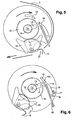
figures 3, 4 ,5 et 6 sont des vues à caractère schématique illustrant le dispositif de coupe, le moyen de sélecteur de format n'étant pas représenté, et le fonctionnement s'effectuant par la distribution d'un format de bandes de matériau en petit format. - les
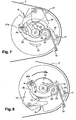
figures 7 à 9 sont des vues à caractère schématique illustrant le dispositif de coupe, le moyen sélecteur étant représenté par son axe, et dans le cadre de la distribution d'un grand format. - la
figure 10 est une vue partielle à caractère schématique illustrant le tambour et les différents composants successifs montés. - la
figure 11 est une vue partielle du flasque support des moyens sélecteur de format.
- the
figure 1 is a schematic view of a dispensing apparatus, the lid is not shown. - the
figure 2 is a partial perspective view of the device of the invention before assembly and illustrating the essential components. - the
Figures 3, 4 ,5 and 6 are schematic views illustrating the cutting device, the format selector means not being shown, and the operation being effected by dispensing a format of strips of material in small format. - the
Figures 7 to 9 are schematic views illustrating the cutting device, the selector means being represented by its axis, and in the context of the distribution of a large format. - the
figure 10 is a partial schematic view illustrating the drum and the various successive components mounted. - the
figure 11 is a partial view of the support flange of the format selector means.
Afin de rendre plus concret l'objet de l'invention, on le décrit maintenant d'une manière non limitative illustrée aux figures des dessins.In order to make the object of the invention more concrete, it is now described in a nonlimiting manner illustrated in the figures of the drawings.
L'appareil distributeur est référencé dans son ensemble par (1) et comprend un carter (2) présentant des flasques (3) (4) latéraux support du tambour (5) incluant un dispositif de coupe d'une part, et la bobine de matériau (7) d'autre part. D'une manière connue, le tambour dont les axes (5a) d'extrémité sont positionnés dans les flasques (3) (4), présente une échancrure (5b) longitudinale susceptible de recevoir le porte-lame (6) support de lame (6a), et ce, d'une manière articulée. Un ressort (8) assure la retenue élastique du porte-lame en étant fixé par une extrémité au moyeu central (5c) du tambour et à l'autre sur ledit porte-lame.The dispensing apparatus is referenced as a whole by (1) and comprises a casing (2) having side flanges (3) (4) supporting the drum (5) including a cutting device on the one hand, and the coil of material (7) on the other hand. In a known manner, the drum whose end axes (5a) are positioned in the flanges (3) (4), has a longitudinal indentation (5b) capable of receiving the blade carrier (6) ( 6a), and this, in an articulated manner. A spring (8) ensures the elastic retention of the blade holder being fixed at one end to the central hub (5c) of the drum and to the other on said blade holder.
Selon l'invention, l'un des côtés transversaux (5d) du tambour (5) présente dans son prolongement une plaque support (10) obtenue par moulage avec la structure dudit tambour et étant déportée par rapport au dit côté latéral (5d). La plaque support présente une ouverture (10a) pour la fixation de l'extrémité (6b) du porte-lame (6). Sur ladite extrémité de ce dernier, est monté un secteur denté (11) établi selon une angulation d'environ 70 à 80° et présentant en extrémité périphérique une pluralité de dents (11a). Ces dents sont susceptibles de coopérer avec une roue dentée (12) montée libre et sous-jacente sur l'axe (5a) du tambour pour permettre ainsi qu'il sera exposé par la suite la sortie de lame de coupe. Ladite roue dentée (12) est solidarisée à une came crochet (13) qui tourne avec cette dernière lors du fonctionnement en rotation du tambour. L'extrémité de l'axe du tambour (5a) reçoit par ailleurs une roue dentée (14) de petit diamètre se prolongeant par une portée de fixation (14a). Parallèlement, le flasque (4) support de l'axe de guidage (5a) précité est lui-même agencé avec une échancrure (4a) pour le positionnement et l'appui de l'axe du tambour. Le tambour (5) présente en plus sur sa face latérale externe (5d) une forme en saillie (15) avec un profil en rampe (15a), cette forme étant solidarisée ou conformée lors du moulage. Le flasque (4) reçoit dans sa partie haute d'une manière rapportée ou monobloc, deux formes fixes constituant butées (16) (17) entre lesquelles est positionné un corps (18) profilé qui est fixé dans sa partie basse par un axe de liaison et de pivotement (19) disposé entre les deux butées précitées. Ce corps est conformé pour avoir une capacité élastique de déformation dans les conditions qui seront définies ci-après. Ce corps comprend une base centrale (18a) allongée dont l'extrémité supérieure (18b) présente un appendice (18c) conformé en L ou en crochet et formant tête, et qui vient se positionner en regard du chant (4c) du flasque (4) en regard, et en léger débordement intérieur par rapport au dit flasque (4). A partir de sa base (18a), le corps (18) présente une languette flexible (18d) dont l'extrémité arrière vient en appui sur la butée (17). Ainsi, ce corps est susceptible d'être sollicité en basculement grâce à sa capacité élastique de déformation et par rapport à son point de fixation et d'articulation (19) sur le flasque (4). Par ailleurs, la partie inférieure (18e) de la tête de ce corps constitue une zone de guidage et de butée par un décrochement (18f) dont la fonction sera précisée par la suite.According to the invention, one of the transverse sides (5d) of the drum (5) has in its extension a support plate (10) obtained by molding with the structure of said drum and being offset with respect to said lateral side (5d). The support plate has an opening (10a) for fixing the end (6b) of the blade holder (6). On said end of the latter, is mounted a toothed sector (11) established at an angle of about 70 to 80 ° and having at the peripheral end a plurality of teeth (11a). These teeth are capable of cooperating with a toothed wheel (12) freely mounted and underlying on the axis (5a) of the drum to thereby allow it to be exposed thereafter the cutting blade outlet. Said toothed wheel (12) is secured to a hook cam (13) which rotates with the latter during operation in rotation of the drum. The end of the axis of the drum (5a) also receives a toothed wheel (14) of small diameter extending by a fixing surface (14a). Meanwhile, the flange (4) support of the aforementioned guide pin (5a) is itself arranged with a notch (4a) for the positioning and support of the axis of the drum. The drum (5) additionally has on its outer lateral face (5d) a protruding shape (15) with a ramp profile (15a), this shape being secured or shaped during molding. The flange (4) receives in its upper part in an attached manner or one-piece, two fixed forms constituting abutments (16) (17) between which is positioned a shaped body (18) which is fixed in its lower part by an axis of link and pivoting (19) disposed between the two abovementioned abutments. This body is shaped to have an elastic capacity of deformation under the conditions that will be defined below. This body comprises an elongate central base (18a) whose upper end (18b) has an appendix (18c) shaped L or hook and forming a head, and which is positioned opposite the edge (4c) of the flange (4). ) facing, and slightly inward overflow relative to said flange (4). From its base (18a), the body (18) has a flexible tongue (18d) whose rear end abuts the abutment (17). Thus, this body is likely to be biased in tilting due to its elastic deformation capacity and relative to its point of attachment and articulation (19) on the flange (4). Moreover, the lower part (18e) of the head of this body constitutes a guiding and abutment zone by a recess (18f) whose function will be specified later.
Selon une autre disposition de l'invention, la partie inférieure (4d) du flasque (4) est susceptible de recevoir un levier coudé (20) qui est monté pivotant par rapport à un axe d'articulation (26) solidarisé au flasque (4) en regard. Ce levier (20) est conformé d'une manière très particulière de part et d'autre de son axe d'articulation. A l'avant, il présente un décrochement (20a) profilé en L, de manière à définir une forme en trident (20b). Cette dernière comprend ainsi deux dents extérieures (20b1) (20b2) entre lesquelles est formée une languette flexible (20b3). L'espace (e) formé entre la dent (20c1) et la languette flexible (20b3) est susceptible d'accueillir un axe profilé (21a) en saillie d'un bouton sélecteur (21) de format. Cette partie profilée (21a) présente un méplat (21b) dont la fonction sera décrite par la suite. Le bouton sélecteur est fixé par vis (27) au flasque (4) de la partie en repère (25). A son extrémité opposée, le levier coudé (20) est susceptible de recevoir par un axe de liaison (22) une roue dentée (23) qui sera susceptible d'engrener avec la roue dentée (14) sous-jacente montée sur l'axe (5a) du tambour (5). La roue dentée (23) reçoit sur sa face (23a) en regard de la paroi du flasque un bossage (24) en saillie formant doigt dont la fonction sera décrite par la suite.According to another embodiment of the invention, the lower part (4d) of the flange (4) is capable of receiving a bent lever (20) which is pivotally mounted relative to a hinge pin (26) secured to the flange (4). ) opposite. This lever (20) is shaped in a very particular way on either side of its axis of articulation. At the front, it has a recess (20a) L-shaped, so as to define a trident shape (20b). The latter thus comprises two outer teeth (20b1) (20b2) between which is formed a flexible tongue (20b3). The space (e) formed between the tooth (20c1) and the flexible tongue (20b3) is capable of accommodating a shaped axis (21a) projecting from a selector knob (21) of format. This profiled portion (21a) has a flat (21b) whose function will be described later. The selector knob is fixed by screws (27) to the flange (4) of the reference part (25). At its opposite end, the bent lever (20) is capable of receiving by a connecting pin (22) a toothed wheel (23) which will be capable of meshing with the gear wheel (14) underlying mounted on the axis (5a) of the drum (5). The toothed wheel (23) receives on its face (23a) facing the wall of the flange a projection (24) projecting finger forming whose function will be described later.
Le bouton sélecteur présente avantageusement un repère (25) permettant d'identifier sa position selon les deux modes de distribution de petit et de grand format.The selector knob advantageously has a marker (25) for identifying its position according to the two modes of small and large format distribution.
La structure de l'invention ayant été décrite, il convient maintenant de procéder à la description du fonctionnement du dispositif de coupe lorsque celui-ci est sollicité pour découper des bandes de matériau dans un premier format, par exemple 20 à 25 cm, ou selon un format plus important double du précédent 40 à 50 cm. On se réfère ainsi aux dessins pour exposer les deux phases de fonctionnement.The structure of the invention having been described, it is now advisable to describe the operation of the cutting device when the latter is urged to cut strips of material in a first format, for example 20 to 25 cm, or according to a larger double format from the previous 40 to 50 cm. The drawings are thus referred to to expose the two phases of operation.
Dans cette situation, le bouton sélecteur (21) se trouve dans une situation telle entre la dent (20b1) et la languette flexible (20b3) de sorte que sa partie méplate (21b) soit en regard de la paroi de la languette. Dans cette situation, ledit levier coudé (20) dans sa partie basse, réceptive de la roue (23), se trouve éloigné du corps (18) précité solidaire du flasque (4) et disposé dans un plan adjacent. Dans cette situation, l'opération de coupe s'effectue de la manière suivante.In this situation, the selector knob (21) is in such a situation between the tooth (20b1) and the flexible tongue (20b3) so that its flat portion (21b) is opposite the wall of the tongue. In this situation, said bent lever (20) in its lower part, receptive to the wheel (23), is located away from the aforementioned body (18) integral with the flange (4) and arranged in an adjacent plane. In this situation, the cutting operation is carried out as follows.
En phase initiale, le tambour (5) en position repos fait que la lame de coupe est escamotée sensiblement à l'intérieur du tambour. Le secteur denté (11) engrène avec la roue dentée (12) montée sur l'axe (5a) du tambour près de son côté latéral associé à la came crochet (13). Dans cette situation, ce sont ces dents (11a) situées à une extrémité du secteur qui sont en contact avec la roue dentée (12). De l'autre côté du flasque, la roue dentée (23) associée au levier coudé (20) engrène avec la roue dentée (14) montée sur l'axe (5a) du tambour (5). Le corps (18) à débattement élastique n'est pas sollicité. Lors de la traction de la bande de matériau par l'opérateur, le tambour est mis en rotation vers l'arrière et seule la roue dentée (12) et la came crochet (13) associée tournent. Le secteur denté (11) n'est soumis à aucun mouvement pour l'instant autour de la roue dentée (12) en regard. La came crochet (13) vient en butée et contact contre la tête du corps flexible (20), et son décrochement en particulier (18f) assurant ainsi un blocage en position. Dans cette situation, sous l'effet de tirage de la bande de matériau, le secteur denté (11) associé au tambour (5) est amené à tourner autour de la roue dentée (12) qui est bloquée en position de part la liaison de la came crochet avec la tête du corps précité. Cela provoque la sortie de la lame de coupe hors du tambour. La rotation continue du tambour amène la forme en saillie (15) qui est solidaire de son côté latéral (5c) à venir à son tour en contact avec la tête flexible du corps (20) et provoquer, en passant dessous, son soulèvement par la capacité élastique de déformation et de relevage de ladite tête. Ce soulèvement se fait grâce à la flexibilité à l'encontre de la languette inférieure dudit corps. Le soulèvement de la tête libère la came crochet (13) qui peut donc basculer avec la roue dentée (12) et revenir en position initiale par l'effet de détente du ressort (8) qui rappelle le porte lame. Le soulèvement de la tête du corps s'effectue lorsque la lame de coupe est en sortie maximum. A chaque tour de tambour, il y a coupe d'une bande de matériau au format sélectionné.In the initial phase, the drum (5) in the rest position makes the cutting blade is retracted substantially inside the drum. The toothed sector (11) meshes with the toothed wheel (12) mounted on the axis (5a) of the drum near its lateral side associated with the hook cam (13). In this situation, it is these teeth (11a) located at one end of the sector that are in contact with the toothed wheel (12). On the other side of the flange, the toothed wheel (23) associated with the bent lever (20) meshes with the toothed wheel (14) mounted on the axis (5a) of the drum (5). The body (18) with elastic displacement is not stressed. When the web of material is pulled by the operator, the drum is rotated backward and only the gearwheel (12) and the associated hook cam (13) rotate. The toothed sector (11) is not subject to any movement for the moment around the toothed wheel (12) opposite. The hook cam (13) comes into abutment and contact against the head of the flexible body (20), and its recess in particular (18f) thereby ensuring a locking position. In this situation, under the pulling effect of the web of material, the toothed sector (11) associated with the drum (5) is rotated around the toothed wheel (12), which is locked in position by means of the link the cam hook with the head of the aforementioned body. This causes the cutting blade to come out of the drum. The continuous rotation of the drum causes the protruding form (15) which is integral with its lateral side (5c) to come in turn in contact with the flexible head of the body (20) and cause, passing underneath, its lifting by the elastic capacity of deformation and lifting of said head. This lifting is done thanks to the flexibility against the lower tongue of said body. The lifting of the head releases the cam hook (13) which can tilt with the toothed wheel (12) and return to the initial position by the triggering effect of the spring (8) which recalls the blade holder. The lifting of the head of the body takes place when the cutting blade is at the maximum output. Each drum revolution, there is cutting a strip of material in the selected format.
Il convient maintenant d'exposer la variante de sélection de format. Dans cette mise en oeuvre, il convient d'agir sur le bouton sélecteur (21) en le faisant tourner d'un demi tour, de sorte à supprimer le contact de la partie méplate (21b) de l'axe du bouton avec les faces en regard des dents du levier coudé (20). L'axe du bouton sélecteur étant de diamètre plus important, cela provoque l'écartement de la languette flexible (20b3) intermédiaire qui vient en contact et poussée sur la dent (20b2) située immédiatement derrière. Cela entraîne un léger pivotement du levier coudé (20) par rapport à son axe de rotation (26). En conséquence, la partie arrière du levier coudé est légèrement surélevée, de sorte à rapprocher le bossage (24) en saillie formant doigt de la roue dentée (23) associée à la partie arrière du levier vers la base inférieure du corps.It is now necessary to expose the format selection variant. In this implementation, it is necessary to act on the selector knob (21) by rotating it by half a turn, so as to eliminate the contact of the flattened portion (21b) of the axis of the button with the faces facing the teeth of the bent lever (20). The axis of the selector knob being of larger diameter, it causes the spacing of the intermediate flexible tongue (20b3) which comes in contact and pushed on the tooth (20b2) located immediately behind. This causes a slight pivoting of the bent lever (20) relative to its axis of rotation (26). Accordingly, the rear portion of the bent lever is slightly raised, so as to bring the projection (24) projecting finger of the toothed wheel (23) associated with the rear portion of the lever towards the lower base of the body.
Une fois le bouton sélecteur mis en position, il convient de décrire le fonctionnement de l'ensemble du dispositif en considérant ainsi la distribution d'une bande de matériau selon un double format. Pour arriver à cette fonction, cela nécessite que la lame de coupe n'intervienne qu'une fois sur deux.Once the selector button is in position, it is necessary to describe the operation of the entire device, thus considering the distribution of a strip of material in a double format. To achieve this function, it requires that the cutting blade intervenes only once in two.
La démarche est donc la suivante. En phase initiale, le secteur denté se trouve en prise par ses dents (11a) avec la roue dentée (12). La traction de la bande de matériau provoque la rotation du tambour vers l'arrière et ainsi la rotation de la roue dentée (12) et de la came crochet (13) qui lui est associée. Cette dernière vient alors en butée contre la tête du corps (20) en provoquant son blocage en position avec la roue (12) associée. La rotation continue provoque le déplacement du secteur denté et du porte lame et donc la sortie de la lame. A cet instant, le bossage formant doigt formé sur la roue (23) se trouve à l'opposé de la face intérieure du corps (20). La rotation continue du tambour amène la forme en saillie (15) solidaire du côté latéral (5d) du tambour (5) à assurer le soulèvement de la tête du corps et la libération de la came crochet (13). La rotation à nouveau du tambour amène cette fois le bossage formant doigt, associé à la roue (23), à provoquer le soulèvement de la tête du corps (20), de sorte à échapper et empêcher tout contact avec la came crochet qui vient une nouvelle fois en regard de cette zone. Dans ces conditions, la came crochet n'est pas freinée et donc sa roue dentée (12) associée non plus, et il n'y a pas action en vue d'assurer la sortie de la lame de coupe. Cela permet, lorsque le bossage formant doigt a passé son point contact avec le corps, d'effectuer ensuite une seconde rotation du tambour, en vue, cette fois-ci, de la sortie de la lame de coupe. En effet, le bossage ne sera plus en contact avec le corps et la came crochet viendra cette fois-ci en contact avec la tête du corps, en entraînant le pivotement du secteur denté et donc la sortie de la lame de coupe puis la forme en saillie viendra soulever ladite tête du corps en libérant la came crochet et autoriser la sortie. Par cette disposition originale, on obtient la distribution d'une bande de matériau en double format.The approach is therefore the following. In the initial phase, the toothed sector is engaged by its teeth (11a) with the toothed wheel (12). Traction of the web of material causes the drum to rotate rearwardly and thus the rotation of the gearwheel (12) and the hook cam (13) associated therewith. The latter then comes into abutment against the head of the body (20) causing its locking in position with the wheel (12) associated. The continuous rotation causes the displacement of the toothed sector and the blade holder and therefore the exit of the blade. At this time, the finger-shaped boss formed on the wheel (23) is opposite the inner face of the body (20). The continuous rotation of the drum causes the protruding form (15) integral with the lateral side (5d) of the drum (5) to ensure the lifting of the head of the body and the release of the hook cam (13). The rotation of the drum again brings this time the finger boss, associated with the wheel (23), to cause the lifting of the head of the body (20), so as to escape and prevent contact with the hook cam which comes a again next to this area. Under these conditions, the hook cam is not braked and therefore its toothed wheel (12) associated either, and there is no action to ensure the output of the cutting blade. This allows, when the finger boss has passed its point of contact with the body, to then perform a second rotation of the drum, in view, this time, the output of the cutting blade. Indeed, the boss will no longer be in contact with the body and the hook cam comes this time in contact with the head of the body, causing the pivoting of the toothed sector and thus the output of the cutting blade and the shape in protrusion will lift said head of the body by releasing the cam hook and allow the exit. By this original arrangement, the distribution of a strip of material in double format is obtained.
Les avantages ressortent bien de la description, en particulier on souligne et on rappelle la simplicité du mécanisme du dispositif, son adaptabilité immédiate par un opérateur au format choisi. Le Demandeur a constaté une grande douceur de fonctionnement du dispositif de coupe. Ainsi, par un nombre de pièces complémentaire limité, on peut assurer cette seconde fonction de sélection de format.The advantages are apparent from the description, in particular emphasizes and reminds the simplicity of the mechanism of the device, its immediate adaptability by an operator in the chosen format. The Applicant has found a great smooth operation of the cutting device. Thus, by a limited number of complementary parts, it is possible to provide this second format selection function.
Claims (9)
- Wipe material dispensing machine comprising a housing (2) with lateral end pieces (3) (4) between which there is a drum (5) that accommodates a blade holder (6) with a cutting blade and a reel of material (7), characterised in that one of the lateral sides of the drum extends laterally as an offset support plate (10) which has an opening (10a) for fixing the end of the blade holder, and in that a toothed sector (11) is mounted on said end with a toothed peripheral end (11a),
and in that the toothed sector cooperates with a gear wheel (12) which is freely mounted on shaft (5a) of the drum and said gear wheel is attached to a hooked cam (13),
and in that the drum has, on the outer face of said lateral side, a protruding shape (15) with a ramp profile (15a),
and in that opposite-facing lateral end piece (4) of the housing which receives the shaft of the drum makes it possible to fix a shaped body (18) located between two fixed limit stops (16) (17), said body exhibiting an elastic pivoting capacity in order for the end thereof which forms appendix (19c) and the head to cooperate either with said hooked cam (13) or with said protruding shape (15) depending on the particular operating phase and pulling of the strip of material. - Machine as claimed in claim 1, characterised in that toothed sector (11) is established over an angle of approximately 70 to 80° and has a plurality of teeth (11a) on its peripheral end.
- Machine as claimed in either claim 1 or 2, characterised in that the end of the shaft (5a) of drum (5) receives a small-diameter gear wheel (14) with connection area (14a).
- Machine as claimed in claim 1, characterised in that the upper part of end piece (4) of the housing accommodates two fixed shapes that constitute limit stops (16) (17) between which body (18) is positioned and the lower part of the body is fixed by connecting pin (19) between the limit stops and to the end piece.
- Machine as claimed in claim 4, characterised in that the body comprises an elongated central base (18a), the upper end (18b) of which has an L-shaped or hook-shaped appendix (18c) that forms a head and positions itself opposite edge (4c) of opposite-facing end piece (4) of the housing and protrudes slightly internally relative to said end piece,
and in that, at its base (18a), body (18) has a flexible tab (18d), the rear end of which presses against limit stop (17),
and in that the lower part (18e) of the head of this body constitutes a guidance and limit stop zone thanks to a discontinuity (18f). - Machine as claimed in claim 5, characterised in that the lower part (4d) of end piece (4) of the housing is capable of receiving a crank (20) that is pivotably mounted relative to a joint pin (26) which is joined to opposite-facing end piece (4),
and in that the crank (20) is shaped at the front either side of its joint pin (26) with an L-shaped discontinuity (20a) so as to define a trident shape (20b),
and in that its end that is opposite crank (20) is capable of receiving, by connecting pin (22), a gear wheel (23) that is capable of meshing with subjacent gear wheel (14) mounted on shaft (5a) of drum (5),
and in that face (23a) of gear wheel (23) which faces the wall of the end piece has a protrusion (24) that forms a protruding finger. - Machine as claimed in claim 6, characterised in that the trident shape comprises two outer teeth (20b1) (20b2) between which there is a flexible tab (20b3).
and in that the gap (e) between tooth (20b1) and flexible tab (20b3) is capable of accommodating a shaped shaft (21a) of knob (21). - Machine as claimed in claim 7, characterised in that knob (21) fulfils a format selection function and in that its shaped shaft (21a) has a flat surface (21b) which, depending on its position, spreads or does not spread flexible tab (20b3) relative to outer teeth (20b1) (20b2) and causes pivoting of said crank relative to its attachment point,
and in that the selector knob is fixed to the end piece by a shaft (27) and that it has a reference mark (25). - Machine as claimed in claim 6, characterised in that the protrusion (24) that forms a protruding finger on gear wheel (23) fulfils the function of spreading body (18) when the crank is pivoted as a result of setting format selector knob (21) in a dual-format selection dispensing situation.
Priority Applications (1)
| Application Number | Priority Date | Filing Date | Title |
|---|---|---|---|
| PL05747033T PL1740079T3 (en) | 2004-04-30 | 2005-04-13 | Wiping material dispenser provided with a cutting device comprising a format selecting unit |
Applications Claiming Priority (2)
| Application Number | Priority Date | Filing Date | Title |
|---|---|---|---|
| FR0404857A FR2869519B1 (en) | 2004-04-30 | 2004-04-30 | WIPING MATERIAL DISPENSING APPARATUS WITH CUTTING DEVICE INCLUDING FORMAT SELECTION CAPACITY |
| PCT/FR2005/050233 WO2005112725A1 (en) | 2004-04-30 | 2005-04-13 | Wiping material dispenser provided with a cutting device comprising a format selecting unit |
Publications (2)
| Publication Number | Publication Date |
|---|---|
| EP1740079A1 EP1740079A1 (en) | 2007-01-10 |
| EP1740079B1 true EP1740079B1 (en) | 2009-03-25 |
Family
ID=34947848
Family Applications (1)
| Application Number | Title | Priority Date | Filing Date |
|---|---|---|---|
| EP05747033A Not-in-force EP1740079B1 (en) | 2004-04-30 | 2005-04-13 | Wiping material dispenser provided with a cutting device comprising a format selecting unit |
Country Status (13)
| Country | Link |
|---|---|
| US (1) | US7637190B2 (en) |
| EP (1) | EP1740079B1 (en) |
| CN (1) | CN100469295C (en) |
| AT (1) | ATE426350T1 (en) |
| AU (1) | AU2005244629B2 (en) |
| BR (1) | BRPI0510490A (en) |
| DE (1) | DE602005013507D1 (en) |
| ES (1) | ES2321529T3 (en) |
| FR (1) | FR2869519B1 (en) |
| MX (1) | MXPA06012392A (en) |
| PL (1) | PL1740079T3 (en) |
| RU (1) | RU2359603C2 (en) |
| WO (1) | WO2005112725A1 (en) |
Families Citing this family (15)
| Publication number | Priority date | Publication date | Assignee | Title |
|---|---|---|---|---|
| FR2859367B1 (en) * | 2003-09-05 | 2006-08-11 | Maurice Granger | DEVICE FOR CONTROLLING THE OUTPUT OF A CUTTING BLADE OF A DRUM IN A TOWING EQUIPMENT DISPENSING DEVICE |
| WO2010044711A2 (en) * | 2008-10-17 | 2010-04-22 | Avramenko Anton | Device for the application and storage of strip-type dressing materials |
| FR2941608B1 (en) * | 2009-02-05 | 2013-03-01 | Maurice Granger | APPARATUS DISRUBUTOR OF WIPING MATERIAL PREDECOUPE WOUND IN A COIL. |
| AT509797A1 (en) * | 2010-04-23 | 2011-11-15 | Hagleitner Hans Georg | METHOD AND DISPENSER FOR THE FLAT-WIDE DELIVERY OF PAPER FROM A STOCK |
| CA2731125A1 (en) * | 2011-02-02 | 2012-08-02 | Hsien-Hsiang Chiu | Toilet paper box |
| FR2978656A1 (en) * | 2011-08-01 | 2013-02-08 | Maurice Granger | WIPING MATERIAL DISPENSER APPARATUS WITH AUTOMATIC CUTTING DEVICE INCLUDING FORMAT SELECTION CAPACITY |
| FR2988577A1 (en) * | 2012-04-03 | 2013-10-04 | Maurice Granger | Apparatus for distributing wiping material into automatic cutting device, has selector device whose locking and barring lever allows fixing position of lever depending on uses and applications of apparatus |
| FR3002133A1 (en) * | 2013-02-19 | 2014-08-22 | Maurice Granger | Distributer apparatus for toilet paper, has casing comprising receiving module, and levers formed in inner side of flanges and cooperating with cams based on operation phases, where levers adjust format of material band to be distributed |
| US12029355B2 (en) | 2015-06-04 | 2024-07-09 | Kimberly-Clark Worldwide, Inc. | Dispenser for rolled sheet materials with motorized spindle |
| US11109722B2 (en) | 2015-06-04 | 2021-09-07 | Charles Agnew Osborne, Jr. | Dispenser for rolled sheet materials |
| US20160353947A1 (en) * | 2015-06-04 | 2016-12-08 | Charles Agnew Osborne, Jr. | Dispenser for rolled sheet materials with motorized spindle |
| US11344165B2 (en) * | 2015-06-04 | 2022-05-31 | Kimberly-Clark Worldwide, Inc. | Dispenser for rolled sheet materials with cutting system |
| GB2552993B (en) * | 2016-08-19 | 2019-10-16 | Achton As | Sheet material dispenser with spring loaded operation trigger |
| US11154166B2 (en) | 2018-05-24 | 2021-10-26 | Charles Agnew Osborne, Jr. | Dispenser for rolled sheet materials |
| CN110111694B (en) * | 2019-05-22 | 2021-12-10 | 上海中航光电子有限公司 | Flexible display module and display device |
Family Cites Families (27)
| Publication number | Priority date | Publication date | Assignee | Title |
|---|---|---|---|---|
| US3459353A (en) * | 1967-08-03 | 1969-08-05 | Erving Paper Mills | Adjustable length sheet dispenser |
| OA04528A (en) * | 1972-04-27 | 1980-03-30 | Granger Maurice | Device for the simultaneous distribution and cutting of coiled material bands. |
| US3998120A (en) * | 1974-04-05 | 1976-12-21 | Sebas S.A. Societe D'exploitation D'appareils Sanitaires | Apparatus for the simultaneous distribution and cutting of strips of rolled materials |
| ES450933A1 (en) | 1975-08-29 | 1977-09-01 | Hoechst Ag | Electrolytic apparatus |
| US5979284A (en) * | 1993-02-01 | 1999-11-09 | Granger; Maurice | Automatic dispensing apparatus for paper towels and toilet paper |
| JP3591672B2 (en) * | 1996-02-05 | 2004-11-24 | 富士写真フイルム株式会社 | Positive photosensitive composition |
| RU2110944C1 (en) * | 1996-12-31 | 1998-05-20 | Александр Геннадьевич Иванов | Paper roll holder |
| FR2771620B1 (en) * | 1997-12-01 | 1999-12-31 | Maurice Granger | WIPING PAPER DISPENSING APPARATUS |
| FR2778077B1 (en) * | 1998-05-04 | 2000-06-16 | Maurice Granger | APPARATUS FOR DISPENSING WIPING MATERIALS AND AUTOMATIC OR SEMI-AUTOMATIC TOILET PAPER |
| FR2778836B1 (en) * | 1998-05-25 | 2000-06-30 | Maurice Granger | DRUM FOR DELIVERY OF WIPING MATERIAL IN A DISPENSING APPARATUS WITH ADJUSTMENT OF THE FORMAT AND LENGTH OF THE MATERIAL DELIVERED |
| FR2778902B1 (en) * | 1998-05-25 | 2000-06-30 | Maurice Granger | WIPER MATERIAL DISPENSING APPARATUS |
| FR2779049B1 (en) * | 1998-05-27 | 2000-06-30 | Maurice Granger | DEVICE FOR INTRODUCING A STRIP OF MATERIAL INTO A WIPING MATERIAL DISPENSING APPARATUS |
| FR2779050B1 (en) * | 1998-05-28 | 2000-06-30 | Maurice Granger | APPARATUS FOR DISPENSING WIPING MATERIALS AND AUTOMATIC OR SEMI-AUTOMATIC TOILET PAPER |
| SE517730C2 (en) * | 1999-06-04 | 2002-07-09 | Karl Gunnar Svensson | Device for removing one or more paper web sections from a rolled paper web |
| FR2799946B1 (en) | 1999-10-26 | 2001-11-23 | Maurice Granger | WIPER MATERIAL DISPENSING APPARATUS |
| US6446901B1 (en) * | 2000-10-10 | 2002-09-10 | Alwin Manufacturing Co., Inc. | Dispenser apparatus with positive stop mechanism |
| FR2828084B1 (en) * | 2001-08-03 | 2003-10-17 | Maurice Granger | WIPER MATERIAL DISPENSING APPARATUS |
| US6820785B2 (en) * | 2001-12-20 | 2004-11-23 | Kimberly-Clark Worldwide, Inc. | Electrical roll product dispenser |
| FR2835418B1 (en) * | 2002-02-01 | 2004-03-26 | Maurice Granger | DEVICE FOR CONTROLLING AND REGULATING THE PRESSURE OF A REEL OF MATERIAL IN AN AUTOMATIC CUT DISPENSER |
| CN2527209Y (en) * | 2002-03-08 | 2002-12-25 | 张凤仪 | Automatic cutting device for toilet paper |
| ITMI20031465A1 (en) * | 2003-07-17 | 2005-01-18 | Steiner Company Internat S A | DEVICE FOR DISPENSING PAPER SHEETS MANUFACTURED FROM A CONTINUOUS RIBBON WITH A SPRING MECHANISM OF A SPARE ROLL |
| JP4060842B2 (en) * | 2004-01-26 | 2008-03-12 | ソノコ・デベロプメント・インコーポレイテッド | Dispenser for web material |
| US20050223860A1 (en) * | 2004-03-30 | 2005-10-13 | Formon John S | Adjustable cutter |
| US7347134B2 (en) * | 2004-09-29 | 2008-03-25 | Kimberly-Clark Worldwide, Inc. | No touch dispenser for sheet material with automatic advance |
| US20070010389A1 (en) * | 2005-07-01 | 2007-01-11 | Scott Paper Limited | Hands-free towel dispenser |
| US7338007B2 (en) * | 2006-03-22 | 2008-03-04 | Eduardo Alfredo Valot | Paper towel dispenser |
| US7837077B2 (en) * | 2006-03-28 | 2010-11-23 | Sca Tissue North America, Llc | Hands-free powered absorbent sheet dispenser |
-
2004
- 2004-04-30 FR FR0404857A patent/FR2869519B1/en not_active Expired - Fee Related
-
2005
- 2005-04-13 MX MXPA06012392A patent/MXPA06012392A/en active IP Right Grant
- 2005-04-13 EP EP05747033A patent/EP1740079B1/en not_active Not-in-force
- 2005-04-13 AU AU2005244629A patent/AU2005244629B2/en not_active Ceased
- 2005-04-13 WO PCT/FR2005/050233 patent/WO2005112725A1/en active Application Filing
- 2005-04-13 BR BRPI0510490-4A patent/BRPI0510490A/en not_active IP Right Cessation
- 2005-04-13 CN CNB2005800184466A patent/CN100469295C/en not_active Expired - Fee Related
- 2005-04-13 RU RU2006142307/12A patent/RU2359603C2/en not_active IP Right Cessation
- 2005-04-13 AT AT05747033T patent/ATE426350T1/en not_active IP Right Cessation
- 2005-04-13 PL PL05747033T patent/PL1740079T3/en unknown
- 2005-04-13 DE DE602005013507T patent/DE602005013507D1/en active Active
- 2005-04-13 US US11/568,126 patent/US7637190B2/en not_active Expired - Fee Related
- 2005-04-13 ES ES05747033T patent/ES2321529T3/en active Active
Also Published As
| Publication number | Publication date |
|---|---|
| ES2321529T3 (en) | 2009-06-08 |
| ATE426350T1 (en) | 2009-04-15 |
| MXPA06012392A (en) | 2007-01-31 |
| US20070215743A1 (en) | 2007-09-20 |
| US7637190B2 (en) | 2009-12-29 |
| AU2005244629A1 (en) | 2005-12-01 |
| FR2869519B1 (en) | 2006-06-16 |
| RU2006142307A (en) | 2008-06-10 |
| EP1740079A1 (en) | 2007-01-10 |
| FR2869519A1 (en) | 2005-11-04 |
| WO2005112725A1 (en) | 2005-12-01 |
| BRPI0510490A (en) | 2007-11-13 |
| CN1964659A (en) | 2007-05-16 |
| RU2359603C2 (en) | 2009-06-27 |
| WO2005112725A9 (en) | 2006-11-16 |
| CN100469295C (en) | 2009-03-18 |
| PL1740079T3 (en) | 2009-08-31 |
| DE602005013507D1 (en) | 2009-05-07 |
| AU2005244629B2 (en) | 2010-07-22 |
Similar Documents
| Publication | Publication Date | Title |
|---|---|---|
| EP1740079B1 (en) | Wiping material dispenser provided with a cutting device comprising a format selecting unit | |
| CA2331057C (en) | Automatic or semi-automatic wiping material and toilet paper dispenser | |
| EP0808122B1 (en) | Folded or unfolded wiping material dispenser apparatus | |
| EP1411808B1 (en) | Wiping material dispenser apparatus | |
| EP0777436B1 (en) | Apparatus for dispensing wiping materials which can be distributed in folded or non folded form | |
| FR2911487A1 (en) | RECEIVER DEVICE FOR COIL OF WIPING MATERIALS AT THE END OF SERVICE FOR A DISPENSER OF WIPING MATERIALS. | |
| EP1512359B1 (en) | Wiping material dispenser with a control mechanism for the appearance of a cutting blade from a drum in the wiping material dispenser | |
| EP1223843B1 (en) | Device for distributing wiping material | |
| EP1463431B1 (en) | Device for controlling and repositioning a roll of wiping material in an automatic-cutting dispenser | |
| EP2816940B1 (en) | Wiping material dispenser apparatus including a device for preventing the material from being rolled back up after being pulled | |
| WO2013017780A1 (en) | Apparatus for dispensing wiping material with automatic cutting device incorporating the ability to select formats | |
| EP0912128B1 (en) | Apparatus for dispensing strips of tissue paper for use as a hand towel, toilet paper and the like | |
| EP1083814A1 (en) | Wiping material dispensing drum in dispensing apparatus with format and length adjustment of the dispensed material | |
| FR2587013A2 (en) | Simplified apparatus for simultaneously delivering and cutting webs of wound materials, with automatic changing of the roll in use | |
| FR2703343A1 (en) | Apparatus for dispensing wiping materials | |
| FR2890302A1 (en) | ASSEMBLY DEVICE FOR BRAKING THE COIL FOR CUTTING IN A DISTRIBUTOR APPARATUS OF AUTOMATIC CUTTING WIPING MATERIALS | |
| EP0889700B1 (en) | Apparatus for dispensing optionally folded wiping materials | |
| FR2891723A1 (en) | ASSEMBLY DEVICE FOR BRAKING THE COIL FOR CUTTING IN A DISPENSER APPARATUS FOR AUTOMATICALLY CUTTING WIPING MATERIALS | |
| FR2889657A1 (en) | WIPING MATERIAL DISPENSING APPARATUS WITH OPERATING NOISE LIMITING DEVICE | |
| FR2799946A1 (en) | - Wiping paper dispenser comprises casing, hood and drum containing cutting blade, drum casing flanges support material reel, pressing roller pivoted by levers provides tension between reel and drum | |
| FR2806284A1 (en) | WIPER MATERIAL DISPENSING APPARATUS | |
| FR2988577A1 (en) | Apparatus for distributing wiping material into automatic cutting device, has selector device whose locking and barring lever allows fixing position of lever depending on uses and applications of apparatus | |
| FR2742737A1 (en) | Paper towel or wipe dispenser | |
| FR2817729A1 (en) | Dispenser for hand wipes or toilet paper comprises drum on which paper is wound, then passing over second drum below it, which carries serrated cutter, shaft (of second drum being extended and free wheel mechanism mounted on it | |
| EP1433409A1 (en) | Device for controlling the drum rotation in a wiping material dispenser |
Legal Events
| Date | Code | Title | Description |
|---|---|---|---|
| PUAI | Public reference made under article 153(3) epc to a published international application that has entered the european phase |
Free format text: ORIGINAL CODE: 0009012 |
|
| 17P | Request for examination filed |
Effective date: 20061020 |
|
| AK | Designated contracting states |
Kind code of ref document: A1 Designated state(s): AT BE BG CH CY CZ DE DK EE ES FI FR GB GR HU IE IS IT LI LT LU MC NL PL PT RO SE SI SK TR |
|
| DAX | Request for extension of the european patent (deleted) | ||
| GRAP | Despatch of communication of intention to grant a patent |
Free format text: ORIGINAL CODE: EPIDOSNIGR1 |
|
| GRAC | Information related to communication of intention to grant a patent modified |
Free format text: ORIGINAL CODE: EPIDOSCIGR1 |
|
| GRAS | Grant fee paid |
Free format text: ORIGINAL CODE: EPIDOSNIGR3 |
|
| GRAA | (expected) grant |
Free format text: ORIGINAL CODE: 0009210 |
|
| AK | Designated contracting states |
Kind code of ref document: B1 Designated state(s): AT BE BG CH CY CZ DE DK EE ES FI FR GB GR HU IE IS IT LI LT LU MC NL PL PT RO SE SI SK TR |
|
| REG | Reference to a national code |
Ref country code: GB Ref legal event code: FG4D Free format text: NOT ENGLISH |
|
| REG | Reference to a national code |
Ref country code: CH Ref legal event code: EP |
|
| REG | Reference to a national code |
Ref country code: IE Ref legal event code: FG4D Free format text: LANGUAGE OF EP DOCUMENT: FRENCH |
|
| REF | Corresponds to: |
Ref document number: 602005013507 Country of ref document: DE Date of ref document: 20090507 Kind code of ref document: P |
|
| REG | Reference to a national code |
Ref country code: ES Ref legal event code: FG2A Ref document number: 2321529 Country of ref document: ES Kind code of ref document: T3 |
|
| REG | Reference to a national code |
Ref country code: SE Ref legal event code: TRGR |
|
| PG25 | Lapsed in a contracting state [announced via postgrant information from national office to epo] |
Ref country code: LT Free format text: LAPSE BECAUSE OF FAILURE TO SUBMIT A TRANSLATION OF THE DESCRIPTION OR TO PAY THE FEE WITHIN THE PRESCRIBED TIME-LIMIT Effective date: 20090325 Ref country code: SI Free format text: LAPSE BECAUSE OF FAILURE TO SUBMIT A TRANSLATION OF THE DESCRIPTION OR TO PAY THE FEE WITHIN THE PRESCRIBED TIME-LIMIT Effective date: 20090325 |
|
| PG25 | Lapsed in a contracting state [announced via postgrant information from national office to epo] |
Ref country code: AT Free format text: LAPSE BECAUSE OF FAILURE TO SUBMIT A TRANSLATION OF THE DESCRIPTION OR TO PAY THE FEE WITHIN THE PRESCRIBED TIME-LIMIT Effective date: 20090325 |
|
| PGFP | Annual fee paid to national office [announced via postgrant information from national office to epo] |
Ref country code: FI Payment date: 20090430 Year of fee payment: 5 Ref country code: NL Payment date: 20090427 Year of fee payment: 5 Ref country code: SE Payment date: 20090422 Year of fee payment: 5 |
|
| REG | Reference to a national code |
Ref country code: PL Ref legal event code: T3 |
|
| REG | Reference to a national code |
Ref country code: IE Ref legal event code: FD4D |
|
| PG25 | Lapsed in a contracting state [announced via postgrant information from national office to epo] |
Ref country code: EE Free format text: LAPSE BECAUSE OF FAILURE TO SUBMIT A TRANSLATION OF THE DESCRIPTION OR TO PAY THE FEE WITHIN THE PRESCRIBED TIME-LIMIT Effective date: 20090325 Ref country code: CZ Free format text: LAPSE BECAUSE OF FAILURE TO SUBMIT A TRANSLATION OF THE DESCRIPTION OR TO PAY THE FEE WITHIN THE PRESCRIBED TIME-LIMIT Effective date: 20090325 Ref country code: PT Free format text: LAPSE BECAUSE OF FAILURE TO SUBMIT A TRANSLATION OF THE DESCRIPTION OR TO PAY THE FEE WITHIN THE PRESCRIBED TIME-LIMIT Effective date: 20090901 |
|
| BERE | Be: lapsed |
Owner name: GRANGER, MAURICE Effective date: 20090430 |
|
| PG25 | Lapsed in a contracting state [announced via postgrant information from national office to epo] |
Ref country code: IS Free format text: LAPSE BECAUSE OF FAILURE TO SUBMIT A TRANSLATION OF THE DESCRIPTION OR TO PAY THE FEE WITHIN THE PRESCRIBED TIME-LIMIT Effective date: 20090725 Ref country code: RO Free format text: LAPSE BECAUSE OF FAILURE TO SUBMIT A TRANSLATION OF THE DESCRIPTION OR TO PAY THE FEE WITHIN THE PRESCRIBED TIME-LIMIT Effective date: 20090325 |
|
| PGFP | Annual fee paid to national office [announced via postgrant information from national office to epo] |
Ref country code: HU Payment date: 20090429 Year of fee payment: 5 |
|
| REG | Reference to a national code |
Ref country code: CH Ref legal event code: PL Ref country code: HU Ref legal event code: AG4A Ref document number: E005934 Country of ref document: HU |
|
| PG25 | Lapsed in a contracting state [announced via postgrant information from national office to epo] |
Ref country code: IE Free format text: LAPSE BECAUSE OF FAILURE TO SUBMIT A TRANSLATION OF THE DESCRIPTION OR TO PAY THE FEE WITHIN THE PRESCRIBED TIME-LIMIT Effective date: 20090325 Ref country code: LI Free format text: LAPSE BECAUSE OF NON-PAYMENT OF DUE FEES Effective date: 20090430 Ref country code: DK Free format text: LAPSE BECAUSE OF FAILURE TO SUBMIT A TRANSLATION OF THE DESCRIPTION OR TO PAY THE FEE WITHIN THE PRESCRIBED TIME-LIMIT Effective date: 20090325 Ref country code: CH Free format text: LAPSE BECAUSE OF NON-PAYMENT OF DUE FEES Effective date: 20090430 Ref country code: BG Free format text: LAPSE BECAUSE OF FAILURE TO SUBMIT A TRANSLATION OF THE DESCRIPTION OR TO PAY THE FEE WITHIN THE PRESCRIBED TIME-LIMIT Effective date: 20090625 |
|
| PLBE | No opposition filed within time limit |
Free format text: ORIGINAL CODE: 0009261 |
|
| STAA | Information on the status of an ep patent application or granted ep patent |
Free format text: STATUS: NO OPPOSITION FILED WITHIN TIME LIMIT |
|
| PGFP | Annual fee paid to national office [announced via postgrant information from national office to epo] |
Ref country code: SK Payment date: 20090402 Year of fee payment: 5 |
|
| 26N | No opposition filed |
Effective date: 20091229 |
|
| PG25 | Lapsed in a contracting state [announced via postgrant information from national office to epo] |
Ref country code: MC Free format text: LAPSE BECAUSE OF NON-PAYMENT OF DUE FEES Effective date: 20090430 |
|
| PG25 | Lapsed in a contracting state [announced via postgrant information from national office to epo] |
Ref country code: BE Free format text: LAPSE BECAUSE OF NON-PAYMENT OF DUE FEES Effective date: 20090430 |
|
| PG25 | Lapsed in a contracting state [announced via postgrant information from national office to epo] |
Ref country code: GR Free format text: LAPSE BECAUSE OF FAILURE TO SUBMIT A TRANSLATION OF THE DESCRIPTION OR TO PAY THE FEE WITHIN THE PRESCRIBED TIME-LIMIT Effective date: 20090626 |
|
| REG | Reference to a national code |
Ref country code: NL Ref legal event code: V1 Effective date: 20101101 |
|
| EUG | Se: european patent has lapsed | ||
| REG | Reference to a national code |
Ref country code: SK Ref legal event code: MM4A Ref document number: E 5970 Country of ref document: SK Effective date: 20100413 |
|
| PG25 | Lapsed in a contracting state [announced via postgrant information from national office to epo] |
Ref country code: FI Free format text: LAPSE BECAUSE OF NON-PAYMENT OF DUE FEES Effective date: 20100413 Ref country code: NL Free format text: LAPSE BECAUSE OF NON-PAYMENT OF DUE FEES Effective date: 20101101 |
|
| PG25 | Lapsed in a contracting state [announced via postgrant information from national office to epo] |
Ref country code: SK Free format text: LAPSE BECAUSE OF NON-PAYMENT OF DUE FEES Effective date: 20100413 Ref country code: HU Free format text: LAPSE BECAUSE OF NON-PAYMENT OF DUE FEES Effective date: 20100414 |
|
| PG25 | Lapsed in a contracting state [announced via postgrant information from national office to epo] |
Ref country code: LU Free format text: LAPSE BECAUSE OF NON-PAYMENT OF DUE FEES Effective date: 20090413 |
|
| PGFP | Annual fee paid to national office [announced via postgrant information from national office to epo] |
Ref country code: GB Payment date: 20110323 Year of fee payment: 7 Ref country code: FR Payment date: 20110516 Year of fee payment: 7 Ref country code: ES Payment date: 20110426 Year of fee payment: 7 |
|
| PG25 | Lapsed in a contracting state [announced via postgrant information from national office to epo] |
Ref country code: TR Free format text: LAPSE BECAUSE OF FAILURE TO SUBMIT A TRANSLATION OF THE DESCRIPTION OR TO PAY THE FEE WITHIN THE PRESCRIBED TIME-LIMIT Effective date: 20090325 |
|
| PGFP | Annual fee paid to national office [announced via postgrant information from national office to epo] |
Ref country code: PL Payment date: 20110318 Year of fee payment: 7 |
|
| PG25 | Lapsed in a contracting state [announced via postgrant information from national office to epo] |
Ref country code: CY Free format text: LAPSE BECAUSE OF FAILURE TO SUBMIT A TRANSLATION OF THE DESCRIPTION OR TO PAY THE FEE WITHIN THE PRESCRIBED TIME-LIMIT Effective date: 20090325 |
|
| PGFP | Annual fee paid to national office [announced via postgrant information from national office to epo] |
Ref country code: IT Payment date: 20110423 Year of fee payment: 7 |
|
| PGFP | Annual fee paid to national office [announced via postgrant information from national office to epo] |
Ref country code: DE Payment date: 20120416 Year of fee payment: 8 |
|
| PG25 | Lapsed in a contracting state [announced via postgrant information from national office to epo] |
Ref country code: SE Free format text: LAPSE BECAUSE OF NON-PAYMENT OF DUE FEES Effective date: 20100414 |
|
| GBPC | Gb: european patent ceased through non-payment of renewal fee |
Effective date: 20120413 |
|
| REG | Reference to a national code |
Ref country code: FR Ref legal event code: ST Effective date: 20121228 |
|
| PG25 | Lapsed in a contracting state [announced via postgrant information from national office to epo] |
Ref country code: GB Free format text: LAPSE BECAUSE OF NON-PAYMENT OF DUE FEES Effective date: 20120413 |
|
| PG25 | Lapsed in a contracting state [announced via postgrant information from national office to epo] |
Ref country code: IT Free format text: LAPSE BECAUSE OF NON-PAYMENT OF DUE FEES Effective date: 20120413 Ref country code: FR Free format text: LAPSE BECAUSE OF NON-PAYMENT OF DUE FEES Effective date: 20120430 |
|
| REG | Reference to a national code |
Ref country code: ES Ref legal event code: FD2A Effective date: 20130716 |
|
| PG25 | Lapsed in a contracting state [announced via postgrant information from national office to epo] |
Ref country code: ES Free format text: LAPSE BECAUSE OF NON-PAYMENT OF DUE FEES Effective date: 20120414 |
|
| REG | Reference to a national code |
Ref country code: PL Ref legal event code: LAPE |
|
| PG25 | Lapsed in a contracting state [announced via postgrant information from national office to epo] |
Ref country code: PL Free format text: LAPSE BECAUSE OF NON-PAYMENT OF DUE FEES Effective date: 20120413 |
|
| PG25 | Lapsed in a contracting state [announced via postgrant information from national office to epo] |
Ref country code: DE Free format text: LAPSE BECAUSE OF NON-PAYMENT OF DUE FEES Effective date: 20131101 |
|
| REG | Reference to a national code |
Ref country code: DE Ref legal event code: R119 Ref document number: 602005013507 Country of ref document: DE Effective date: 20131101 |