EP1738488B1 - Satellitenüberwachung - Google Patents
Satellitenüberwachung Download PDFInfo
- Publication number
- EP1738488B1 EP1738488B1 EP04702756A EP04702756A EP1738488B1 EP 1738488 B1 EP1738488 B1 EP 1738488B1 EP 04702756 A EP04702756 A EP 04702756A EP 04702756 A EP04702756 A EP 04702756A EP 1738488 B1 EP1738488 B1 EP 1738488B1
- Authority
- EP
- European Patent Office
- Prior art keywords
- signal
- satellite
- copy
- channel
- monitoring
- Prior art date
- Legal status (The legal status is an assumption and is not a legal conclusion. Google has not performed a legal analysis and makes no representation as to the accuracy of the status listed.)
- Expired - Lifetime
Links
Images




Classifications
-
- H—ELECTRICITY
- H04—ELECTRIC COMMUNICATION TECHNIQUE
- H04B—TRANSMISSION
- H04B7/00—Radio transmission systems, i.e. using radiation field
- H04B7/14—Relay systems
- H04B7/15—Active relay systems
- H04B7/204—Multiple access
- H04B7/2041—Spot beam multiple access
-
- H—ELECTRICITY
- H04—ELECTRIC COMMUNICATION TECHNIQUE
- H04B—TRANSMISSION
- H04B7/00—Radio transmission systems, i.e. using radiation field
- H04B7/14—Relay systems
- H04B7/15—Active relay systems
- H04B7/185—Space-based or airborne stations; Stations for satellite systems
- H04B7/1851—Systems using a satellite or space-based relay
- H04B7/18513—Transmission in a satellite or space-based system
Definitions
- the present invention relates to satellite monitoring, and particularly, but not exclusively, to a method, apparatus, system and computer program for terrestrial monitoring of the transmission performance of a multi-beam satellite.
- Operators of satellite systems need to monitor various transmission properties of their satellites, such as the centre frequencies of frequency channels, carrier to noise ratios (C/No), link quality and Effective Isotropic Radiated Power (EIRP). Some or all of these properties may be measured directly or indirectly by receiving user terminals and reported back to the system, for example to assist in power control, Doppler correction or variable data rate techniques.
- C/No carrier to noise ratios
- EIRP Effective Isotropic Radiated Power
- Some or all of these properties may be measured directly or indirectly by receiving user terminals and reported back to the system, for example to assist in power control, Doppler correction or variable data rate techniques.
- the availability and geographical spread of user terminals is outside the control of the satellite operator, which cannot therefore rely on user terminals for comprehensive monitoring of the transmission properties of a satellite.
- the InmarsatTM mobile satellite communications system includes a plurality of geostationary Inmarsat-3TM satellites 2, one of which is shown in Figure 1 .
- the satellite 2 generates a global beam 6 and five spot beams 8a-e which fall within the global beam 6, the beam patterns being substantially coterminous for transmission and reception.
- the spot beams 8a-e are used predominantly for communications traffic, while the global beam 6 is used predominantly for call set-up and communications traffic outside the coverage of the spot beams 6.
- a plurality of land earth stations (LES) 4a-b act as satellite base stations and gateways to terrestrial networks.
- Each LES 4 communicates at C-band over a bidirectional feeder link 10 via the satellite 2, which maps frequency channels within the feeder link 10 to corresponding beams and L-band channels within the beams, according to a variable channel mapping configured on the satellite 2 under the control of a telemetry, tracking and control (TT&C) station (not shown).
- T&C tracking and control
- a remote monitoring station (RMS) 12 needs to be located in each spot beam 8.
- the RMS 12 receives a current frequency plan, monitors L-band channels within the relevant spot beam or beams 8, and records channel measurements from which the required transmission properties of the satellite 2 can be derived.
- Each RMS must be kept operational as near continuously as possible, and must be calibrated so that the measurement results are reliable; therefore, it is convenient to collocate RMSs 12a, 12b with LESs 4a, 4b so that existing maintenance facilities can be used.
- the RMSs 12 must transmit monitoring data so that it can be processed by a central server.
- the data may be transmitted over the satellite network, or over a wireline network such as an ISDN. Therefore, collocated RMSs 12a, 12b have the advantage of being able to use existing communications facilities at the LESs 4a, 4b to transmit this data.
- the collocated RMS 12b is able to monitor both spot beams 8c, 8d, thus reducing the number of RMSs 12 required.
- a transportable monitoring station (TMS) 12c, 12d may be provided.
- the TMSs 12c, 12d are conveniently located where suitable maintenance and/or terrestrial communication facilities are available. However, it is more difficult to provide the necessary maintenance and communications facilities to the TMSs 12c, 12d than to collocated RMSs 12a, 12b.
- the Inmarsat-4TM satellites will have reconfigurable beam patterns, so that a distribution of monitoring stations 12 adequate to monitor one beam pattern configuration may not be adequate to monitor another.
- the problems described above are not unique to InmarsatTM satellite communications systems. As the demand for high-bandwidth satellite communications increases, the number of spot beams required also increases, to provide the necessary gain and frequency re-use for high bandwidth services.
- the problems are not unique to geostationary satellites, and may be more acute for non-geostationary satellites which generate a moving beam pattern.
- the problems are not unique to repeater satellites, and may be more acute with switching satellites, which may have fewer terrestrial gateways which can be used for satellite monitoring.
- EP 1353454 describes a multi-beam satellite communications system for distributing information to user terminals located within a plurality of spot beams.
- US 3541553 describes a technique for generating multi-beam transmissions by illuminating different areas of a reflector of an antenna.
- US 6597312 describes a phased array antenna system including a plurality of antenna elements.
- the phased array antenna system generates two or more separate planar phase fronts with a common phase center so as to form two or more beams and to steer the beams in different directions.
- US 2003/0052819 describes a technique for increasing beam traffic capacity of a multi-beam antenna communication system.
- the technique utilizes a composite transmit signal for transmitting a signal towards a remote user, the composite transmit signal containing a copy of the signal being transmitted towards each of the other nearby remote users.
- the phase/amplitude of the copies are selected so as to cancel interference at the remote user.
- EP 1526605 describes a technique for multi-beam transmission by an active phased array antenna. This document mentions that the signals transmitted to different beams may be different from or same as each other at paragraph. However, the multi-beam transmission technique is only used for normal user data transmission to user terminals.
- an apparatus for configuring a multi-beam satellite to enable remote monitoring of transmissions of the satellite as set out in claim 23 is provided.
- a multibeam satellite is controlled to transmit a duplicate of a channel from one spot beam in another spot beam, which contains a remote monitoring station. Instead of arranging a monitoring station in the monitored spot beam, the monitored spot beam is duplicated to the monitoring station. The monitored spot beam itself, and the traffic contained within it, need not be affected. In this way, the need to have a monitoring station in each spot beam may be overcome.
- the duplicate channel contains a duplicate signal having the same modulated content, modulation scheme and power level as the original signal, so that the monitored properties of the duplicate channel are representative of the original channel.
- the duplicate signal may be shifted in frequency from the original signal. This may avoid interference between the original and duplicate signals, and may facilitate frequency coordination in a frequency re-use pattern.
- the duplicate channel may be at a frequency reserved for monitoring and not used for original channels.
- the duplicate signal may partially or completely overlap in frequency with the original channel. In this case, interference may be avoided by spatial isolation between the spot beams containing the original and duplicate channels.
- the monitored channel may be a frequency channel containing a variable allocation of user channels divided by frequency, time, code and/or other multiple access methods.
- the monitoring station may receive a frequency plan identifying the allocation of the user channels to the frequency channel, identify a specific user channel from the frequency plan, and monitors transmission properties of the specific user channel.
- the monitoring station does not decode the data content of the monitored signal and is not used for call interception purposes.
- the channel to be duplicated is variable, so that the duplicate channel transmitted to the remote monitoring station is a duplicate of different channels at different times.
- the channel to be duplicated may be freely selectable from any of the channels in use, subject to any interference constraints.
- the original and duplicate channels may be generated by the satellite from a single channel received in a feeder link.
- the invention may differ from a multicasting technique in which the same channel is transmitted in a plurality of beams for reception by a plurality of users.
- a multicasting technique the allocation of a channel to the plurality of beams is not reconfigured, and may not be reconfigurable, during a multicast transmission.
- a multicast will normally be addressed to a set of receivers and will be transmitted only in the beams within which those receivers are located.
- the spot beam within which a transmission is duplicated may be selected independently of the content of the transmission or of any signalling by which the transmission was set up. Instead, the spot beam may be selected to cover a remote monitoring station which is to monitor the transmission. Furthermore, the invention is applicable to transmissions which are set up as unicast transmissions, although it may also be applicable to multicast transmissions.
- FIG. 2 shows schematically a multibeam satellite communications system according to an embodiment of the present invention.
- a satellite 2 generates a large number of spot beams 8 within the coverage area of its global beam 6.
- the spot beams 8 are arranged in an approximately hexagonal beam pattern covering most of the terrestrial and coastal areas within the field of view of the satellite 2.
- Each beam is represented as having a hexagonal shape, for clarity, but in reality will have an approximately circular shape distorted by the projection of the beam onto the surface of the earth.
- a frequency re-use pattern may be applied so that the same frequency channel is re-used between spot beams 8 having at least a minimum separation distance.
- the spot beams 8 carry user traffic and signalling for reception by user terminals; a representative user terminal 5 is shown in Figure 2 , but the system is able to provide satellite communications services to a large number of such terminals.
- An LES 4 provides a feeder link 10 to the satellite; although the feeder link is bidirectional, we need only consider the forward direction in this embodiment.
- Each frequency channel at C-band in the feeder link 10 is mapped by the satellite 2 to a corresponding spot beam 8 determined by a channel filter configuration on board the satellite 2. Note that different frequency channels in the feeder link 10 may be mapped to the same frequency in different ones of the spot beams separated by the minimum separation distance.
- spot beams 8i-8m Five representative spot beams 8i-8m will be considered, although the example can be extrapolated to all of the spot beams 8. None of these spot beams 8i-8m covers an RMS 12, yet all of them need to be monitored.
- monitoring is achieved by configuring the channel filter to duplicate transmissions in one of the spot beams 8i-8m into another spot beam 8n which is monitored by an RMS 12.
- the channel filter is reconfigured periodically to select each of the spot beams 8i-8m in turn for duplicate transmission.
- the RMS 12 monitors the duplicate transmissions to derive the satellite transmission properties for the corresponding transmissions being duplicated at that time.
- the RMS 12, or the facility which collects the monitored data may compensate for any differences in beam geometry between the monitored spot beam 8i-8m and the spot beam 8n containing the duplicate transmissions.
- the duplicate transmissions for each of the spot beams 8i-8m are transmitted into the same frequency channel, which is reserved for duplicate transmissions to avoid interference with normal transmissions intended for reception by user terminals.
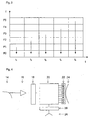
- This arrangement is illustrated graphically in Figure 3 , where transmissions in frequency channels F1 to F5 and corresponding to spot beams 8i-8m, are duplicated into the reserved frequency channel F0 in spot beam 8n in successive time periods t1 to t5.
- the duplicate frequency channel is selected from any of the available channels, subject to any interference constraint.
- This alternative has the advantage that the frequency channel F0 can be used for user traffic, thus increasing the frequency usage efficiency of the system.
- it imposes a constraint on the frequency re-use pattern, because two frequency channels are assigned simultaneously to the spot beam 8n containing the RMS 12, neither of which frequency channels can be re-used within the minimum re-use distance. The effect of this constraint could be overcome at least partially if the spot beam 8n is at the edge of the spot beam pattern.
- the duplicate transmission may be transmitted at a significantly lower gain than the original transmission, because the RMS 12 has an antenna gain significantly higher than that of the user station or stations for which the original transmission is generated.
- the gain may be at least 3 dB lower, and preferably 6 dB lower.
- the lower gain reduces the interference caused by duplicate transmissions.
- the gain may be sufficiently low that it does not impose a constraint on the frequency re-use pattern.
- a selected transmission may be duplicated simultaneously into a plurality of different spot beams for monitoring by a corresponding plurality of different RMS 12.
- the monitored signals may be compared at a monitoring facility and atmospheric effects attributable to the different paths travelled by the different duplicate transmissions may be cancelled. In this way, the transmission properties of the original signal as transmitted by the satellite may be more accurately determined.
- a known test signal may be transmitted to the satellite and the channel filter configured to transmit the same test signal in at least two different spot beams for monitoring by different RMS.
- the received test signals may be compared at a monitoring facility in order to measure atmospheric properties along the different paths travelled by the test signal to the different RMS.
- the atmospheric properties determined in this way may include ionospheric delay, which is frequency dependent.
- a test signal including components at different frequencies can be used to determine ionospheric delay along each path.
- the RMS 12 may be collocated with the LES 4.
- the frequency plan may be shared locally between the LES 4 and the RMS 12. This alternative does not pose any additional interference problem, as the feeder link 10 is at C-band, while the spot beam transmissions are at L-band.
- a C-band antenna 14 receives feeder link channel transmissions from the LES 4, which are amplified by a low noise amplifier (LNA) 16 and digitally converted by an analog-to-digital (A/D) converter 18.
- LNA low noise amplifier
- A/D analog-to-digital
- a digital beam former and channeliser 20 performs the mapping between feeder link channels and frequency channels in spot beams 8, and outputs a set of analog converted signals which are amplified by a bank of high power amplifiers (HPAs) 22 and fed to a corresponding set of antenna elements in an L-band antenna. The sum of signals radiated by the antenna elements generates the spot beam pattern.
- HPAs high power amplifiers
- the channel filter configuration is controlled by commands received from a Telemetry, Tracking and Control (TT&C) station by a TT&C antenna 26, demodulated and decoded by a TT&C interface 28 and provided as input to the digital beam former and channeliser 20.
- TT&C Telemetry, Tracking and Control
- Each frequency channel may be subdivided in frequency and time to define individual user channels, with differing modulation schemes.
- the format of each frequency channel is transparent to the satellite payload, which provides 200 kHz channelization of transmitted signals, but the RMS 12 must be able to distinguish the individual user channels in order to identify various properties of the user channels, such as the centre frequency and the C/No ratio.
- FIG. 5 shows a simplified version of the remote monitoring system network architecture, including representative RMSs 12a and 12b which are preferably co-located with respective LESs 4a and 4b.
- Each RMS 12 includes a spectrum analyser 30 which is calibrated by calibration equipment 32 and controlled by an RMS controller 34 to perform the required monitoring functions
- a Global Resource Manager (GRM) 38 stores a map of the satellite filter configuration and controls the satellite 2 to modify the satellite filter configuration through a payload control system 36 which communicates the modifications to the satellite 2 via the RMS 12a or another TT&C station.
- the GRM 38 copies the map to each RMS 12 and informs the RMSs 12 when duplicate channels have been allocated or deallocated.
- one of the RMSs 12 requests the GRM 38 to set up a duplicate filter for the channel to be monitored.
- the PCS 36 sets up the duplicate channel and confirms to the GRM 38 that the channel has been set up.
- the GRM 38 communicates the confirmation to the RMS 12, which then carries out the measurement, stores the result, and requests the GRM 38 to set up the next duplicate channel.
- the timing and order of measurement of the different channels is flexible and can be set up by the RMS 12 according to requirements rather than in a fixed sequence.
- Each RMS 12 is connected through a wide-area network (WAN) 40 to a monitoring server 42, which instructs the RMSs 12 to request and measure duplicate channels, and receives the resultant monitoring data from them.
- the monitoring server 40 also accesses the current frequency plan 44 and distributes information about the intended format of the channel to the relevant RMS 12.
- the satellite 2 is an Inmarsat-3TM satellite having a relatively small number of spot beams.
- the aim of this embodiment is to reduce or eliminate the requirement for transportable monitoring stations (TMSs) 12c, 12d.
- TMSs transportable monitoring stations
- a problem associated with this embodiment is that, because the size of each beam is large and the number of different channel sets defined for frequency re-use is small, it is more difficult to avoid interference between the duplicate channel set and the normal channel sets.
- the duplicate beam must be sufficiently spatially isolated from the normal beams which use the same frequency spectrum.
- the Inmarsat-3TM satellite includes a redundant filter which is switchable into the transmission path as a backup if the primary filter fails.
- the redundant filter may also be used in parallel with the primary filter.
- the redundant filter is driven by a different local oscillator from the primary filter, which may be driven at a different frequency so as to transmit the duplicate channel at a different frequency.
- the redundant filter is used to duplicate the channel set to be monitored into a spot beam where one of the RMSs 12 is located.
- the gain of the duplicate channel may be significantly lower than that of the original channel.
- Figure 6 shows an example of the spot beam coverage of the Inmarsat-3TM Indian Ocean Region (IOR) satellite
- Figure 7 shows the spectrum allocations of the primary filter PF and the redundant filter RF. Any particular frequency channel can be used twice with sufficient spatial isolation, so the frequency allocation of each filter is illustrated for clarity with upper and lower bands RFa, RFb, PFa, PFb. However, it should be appreciated that each band corresponds to the same frequency spectrum.
- the reference numerals 8a to 8e indicate respectively the southwest, northwest, north central, northeast and southeast beams, and are used in Figure 7 to indicate the portion of the frequency spectrum allocated to each beam.
- At least two RMSs 12 are available for each satellite 2, and these are preferably collocated with an LES 4 to allow re-use of existing facilities.
- FIG 10 shows the network configuration of the remote monitoring system in this embodiment. Like components to those of the first embodiment are indicated by the same reference numerals as those of Figure 5 . Compared with the configuration of the first embodiment, there is no GRM 38 or PCS 36. Instead, each RMS 12 monitors channel allocation signalling on the satellite network to determine the channel allocation within the spectrum to be monitored. The redundant filter is configured by transmissions from the TT&C stations, which may be collocated with the RMS 12 or LES 4.
Landscapes
- Engineering & Computer Science (AREA)
- Computer Networks & Wireless Communication (AREA)
- Signal Processing (AREA)
- Physics & Mathematics (AREA)
- Astronomy & Astrophysics (AREA)
- Aviation & Aerospace Engineering (AREA)
- General Physics & Mathematics (AREA)
- Radio Relay Systems (AREA)
- Mobile Radio Communication Systems (AREA)
- Aerials With Secondary Devices (AREA)
- Transition And Organic Metals Composition Catalysts For Addition Polymerization (AREA)
- Analysing Materials By The Use Of Radiation (AREA)
- Medicines Containing Antibodies Or Antigens For Use As Internal Diagnostic Agents (AREA)
Claims (23)
- Verfahren zum Konfigurieren eines vielstrahlensatelliten (2), um eine Fernüberwachung seiner Übertragungen zu ermöglichen, wobei der Satellit (2) ein Signal in einem ersten Strahl (8i) an ein Anwenderendgerät zum Empfangen des Signals überträgt, wobei das Verfahren das Konfigurieren des Satelliten (2) umfasst, um eine Kopie des Signals in einem zweiten Strahl (8n) zu übertragen, der ausgewählt wurde, um eine entfernte Überwachungsstation (12) zur Überwachung der Kopie zu enthalten, dadurch gekennzeichnet, dass die Kopie in dem zweiten Strahl (8n) in einem Kanal übertragen wird, der sich von dem unterscheidet, der zur Anwenderdatenübertragung an Anwenderendgeräte in dem zweiten Strahl (8n) verwendet wird.
- Verfahren nach Anspruch 1, wobei die Kopie mit einer wesentlich geringeren Verstärkung als das Signal übertragen wird.
- Verfahren nach Anspruch 1 oder 2, wobei das Signal und die Kopie im Wesentlichen mit derselben Frequenz übertragen werden.
- Verfahren nach Anspruch 1 oder 2, wobei das Signal mit einer ersten Frequenz und die Kopie mit einer zweiten Frequenz, die sich von der ersten Frequenz unterscheidet, übertragen werden.
- Verfahren nach Anspruch 4, wobei die Kopie des Signals in einem Kanal übertragen wird, der für die Überwachung durch die entfernte Überwachungsstation (12) reserviert ist.
- Verfahren nach einem der Ansprüche 1 bis 5, wobei die Kopie des Signals in einer Vielzahl verschiedener Strahlen, einschließlich dem zweiten Strahl (8n), übertragen wird.
- Verfahren nach Anspruch 6, wobei die Vielzahl von Strahlen so ausgewählt wird, so dass jeder eine entfernte Überwachungsstation (12) zur Überwachung der Kopie enthält.
- Verfahren nach einem der vorangegangenen Ansprüche, wobei der Satellit (2) ein Relaissatellit ist, der konfigurierbar ist, um ein Zuführungsverbindungssignal, welches von einem Erd-Gateway an den Satelliten (2) übertragen wird, in das Signal und die Kopie des Signals umzuwandeln.
- Verfahren nach einem der vorangegangenen Ansprüche, wobei das Signal an das Anwenderendgerät adressierte Anwenderdaten enthält.
- Verfahren nach einem der vorangegangenen Ansprüche, wobei der Schritt des Konfigurierens das direkte oder indirekte Übertragen eines Konfigurationsbefehls an den Satelliten (2) umfasst.
- Verfahren nach einem der vorangegangenen Ansprüche, das ferner das direkte oder indirekte Übertragen von Kanalzuordnungsdaten, die eine Zuordnung von einem oder mehreren Anwenderkanälen innerhalb des Signals identifizieren, an die entfernte Überwachungsstation (12) umfasst, so dass die entfernte Überwachungsstation (12) den einen oder die mehreren Anwenderkanäle überwacht.
- Verfahren nach Anspruch 1, wobei der Satellit (2) zusätzlich ein oder mehrere Signale in einem oder mehreren entsprechenden zusätzlichen Strahlen (8j-8m) überträgt, wobei der Satellit (2) periodisch neu konfiguriert wird, um aus dem Signal und dem einen oder den mehreren Signalen verschiedene Signale auszuwählen, um eine Kopie davon in dem zweiten Strahl (8n) zu übertragen.
- Verfahren nach Anspruch 12, wobei der Satellit (2) periodisch neu konfiguriert wird, so dass jedes Signal von dem Signal und dem einen oder den mehreren Signalen der Reihe nach überwacht wird.
- Verfahren zur Überwachung einer Übertragung eines Signals von einem Vielstrahlensatelliten (2) in einem ersten Strahl (8i), wobei das Verfahren das Empfangen einer Kopie des Signals in einem zweiten Strahl (8n) des Satelliten (2) und die Überwachung der Kopie des Signals umfasst, dadurch gekennzeichnet, dass die Kopie in dem zweiten Strahl (8n) in einem Kanal empfangen wird, der sich von dem unterscheidet, der zur Anwenderdatenübertragung an die lanwenderendgeräte in dem zweiten Strahl (8n) verwendet wird.
- Verfahren nach Anspruch 14, wobei die Kopie des Signals mit einer anderen Frequenz als der des Signals empfangen wird.
- Verfahren nach Anspruch 15, wobei die Kopie des Signals in einem für die Überwachung reservierten Kanal empfangen wird.
- Verfahren nach Anspruch 14, wobei die Kopie des Signals mit derselben Frequenz wie das Signal empfangen wird, und sich der zweite Strahl (8n) nicht neben dem ersten Strahl (8i) befindet.
- Verfahren nach einem der Ansprüche 14 bis 17, wobei die Verstärkung der Kopie wesentlich geringer ist als die des Signals.
- Verfahren nach einem der Ansprüche 14 bis 18, wobei das Signal an ein Anwenderendgerät adressierte Anwenderdaten enthält.
- Verfahren nach einem der Ansprüche 14 bis 19, ferner umfassend das Empfangen von Kanalzuordnungsdaten, die eine Zuordnung von einem oder mehreren Anwenderkanälen innerhalb des Signals identifizieren, und die Überwachung des einen oder der mehreren Anwenderkanäle.
- Computerprogramm, das eingerichtet ist, um das Verfahren nach einem der vorangegangenen Ansprüche auszuführen.
- Computerprogrammprodukt, welches ein Computerprogramm nach Anspruch 21 enthält.
- Vorrichtung zum Konfigurieren eines Vielstrahlensatelliten (2), um die entfernte Überwachung von Übertragungen des Satelliten (2) zu ermöglichen, wobei der Satellit (2) bedienbar ist, um ein Signal in einem ersten Strahl (8i) an ein Anwenderendgerät zum Empfangen des Signals zu übertragen, wobei die Vorrichtung gekennzeichnet ist durch:Mittel zum Konfigurieren des Satelliten, um in einem zweiten Strahl (8n) eine Kopie des Signals zu übertragen, in einem Kanal, der sich von dem unterscheidet, der für die Anwenderdatenübertragung an Anwenderendgeräte in dem zweiten Strahl (8n) verwendet wird, wobei der zweite Strahl (8n) ausgewählt wird, um eine entfernte Überwachungsstation (12) zur Überwachung der Kopie zu enthalten.
Applications Claiming Priority (1)
| Application Number | Priority Date | Filing Date | Title |
|---|---|---|---|
| PCT/GB2004/000226 WO2005067367A2 (en) | 2004-01-16 | 2004-01-16 | Satellite monitoring |
Publications (2)
| Publication Number | Publication Date |
|---|---|
| EP1738488A2 EP1738488A2 (de) | 2007-01-03 |
| EP1738488B1 true EP1738488B1 (de) | 2009-09-30 |
Family
ID=34778746
Family Applications (1)
| Application Number | Title | Priority Date | Filing Date |
|---|---|---|---|
| EP04702756A Expired - Lifetime EP1738488B1 (de) | 2004-01-16 | 2004-01-16 | Satellitenüberwachung |
Country Status (9)
| Country | Link |
|---|---|
| US (1) | US7792485B2 (de) |
| EP (1) | EP1738488B1 (de) |
| JP (1) | JP4562738B2 (de) |
| CN (1) | CN101160750B (de) |
| AT (1) | ATE444607T1 (de) |
| AU (1) | AU2004313310B2 (de) |
| CA (1) | CA2553271A1 (de) |
| DE (1) | DE602004023437D1 (de) |
| WO (1) | WO2005067367A2 (de) |
Families Citing this family (16)
| Publication number | Priority date | Publication date | Assignee | Title |
|---|---|---|---|---|
| US20080055153A1 (en) * | 2006-08-29 | 2008-03-06 | Wildblue Communications, Inc. | Network-Access Satellite Communication System |
| US8730086B2 (en) | 2008-08-26 | 2014-05-20 | Viasat, Inc. | Weather detection using satellite communication signals |
| US8538328B2 (en) | 2008-09-11 | 2013-09-17 | Viasat, Inc. | Antenna and satellite alignment using beam projections |
| US8660142B2 (en) | 2008-09-25 | 2014-02-25 | Viasat, Inc. | Scheduling virtual bandwidth requests |
| US8411798B2 (en) | 2008-11-05 | 2013-04-02 | Viasat, Inc. | Reducing receiver power dissipation |
| US8000259B2 (en) | 2009-09-04 | 2011-08-16 | Viasat, Inc. | Distributed cache—adaptive multicast architecture for bandwidth reduction |
| EP2365646A1 (de) | 2010-03-12 | 2011-09-14 | Inmarsat Global Limited | Überwachung eines Antennenstrahls eines Satelliten durch einen Überwachungssatelliten |
| JP2011004419A (ja) * | 2010-08-10 | 2011-01-06 | Sharp Corp | 中継方法 |
| KR101719826B1 (ko) * | 2011-11-28 | 2017-03-27 | 한국전자통신연구원 | 통신 위성 감시 장치 및 방법 |
| KR20140041074A (ko) | 2012-09-27 | 2014-04-04 | 한국전자통신연구원 | 위성 서비스 자원 관리 장치 및 방법 |
| GB2513302A (en) | 2013-04-15 | 2014-10-29 | Inmarsat Global Ltd | Transmitter positioning for satellite communications |
| CN103490808B (zh) * | 2013-08-12 | 2016-06-22 | 上海卫星工程研究所 | 基于扩频体制的星载s频段中继用户终端系统及应用方法 |
| US9407534B2 (en) * | 2014-05-27 | 2016-08-02 | Telefonaktiebolaget L M Ericsson (Publ) | Enhanced procedure to compute LFAs with IGP max metric |
| US9967792B2 (en) | 2015-03-16 | 2018-05-08 | Space Systems/Loral, Llc | Communication system with multi band gateway |
| WO2017109955A1 (ja) * | 2015-12-25 | 2017-06-29 | 三菱電機株式会社 | 通信衛星、回線制御装置および衛星通信システム |
| US10440596B2 (en) | 2017-09-19 | 2019-10-08 | Hughes Network Systems, Llc | Measuring and monitoring beam performance in mobile satellite system |
Family Cites Families (16)
| Publication number | Priority date | Publication date | Assignee | Title |
|---|---|---|---|---|
| US3541553A (en) * | 1968-03-27 | 1970-11-17 | Rca Corp | Satellite communications systems |
| JPS6413825A (en) * | 1987-07-08 | 1989-01-18 | Hitachi Ltd | Transmission power controller |
| JPH07209408A (ja) * | 1993-12-02 | 1995-08-11 | Toshiba Corp | 静止衛星のgpsオーバーレイシステム |
| FR2742283B1 (fr) * | 1995-12-06 | 1998-02-06 | Telediffusion Fse | Procede et dispositif de reduction du brouillage de transmission hertzienne en reseau |
| US5710971A (en) * | 1995-12-18 | 1998-01-20 | Motorola, Inc. | Radio communication network and method for unobstrusive call interception via data duplication |
| US5924015A (en) * | 1996-04-30 | 1999-07-13 | Trw Inc | Power control method and apparatus for satellite based telecommunications system |
| JPH1141122A (ja) * | 1997-07-15 | 1999-02-12 | Nippon Telegr & Teleph Corp <Ntt> | 通信装置 |
| EP1353454A3 (de) * | 1999-09-27 | 2005-10-19 | EMS Technologies, Inc. | Mehrstrahlsatellitenkommunikationssystem |
| US6704543B1 (en) * | 1999-09-27 | 2004-03-09 | Ems Technologies, Inc. | Multi-beam satellite communications system |
| US7257418B1 (en) * | 2000-08-31 | 2007-08-14 | The Directv Group, Inc. | Rapid user acquisition by a ground-based beamformer |
| US6934508B2 (en) * | 2001-03-19 | 2005-08-23 | Navigaug Inc. | System and method for obtaining comprehensive vehicle radio listener statistics |
| US6642883B2 (en) * | 2001-08-30 | 2003-11-04 | Lockheed Martin Corporation | Multi-beam antenna with interference cancellation network |
| US6597312B1 (en) * | 2002-01-30 | 2003-07-22 | Northrop Grumman Corporation | Phased array antenna system generating multiple beams having a common phase center |
| US6965755B1 (en) * | 2002-11-08 | 2005-11-15 | The Directv Group, Inc. | Comprehensive network monitoring at broadcast satellite sites located outside of the broadcast service area |
| US6856284B1 (en) * | 2003-10-22 | 2005-02-15 | Itt Manufacturing Enterprises, Inc. | Methods and apparatus for multi-beam, multi-signal transmission for active phased array antenna |
| US7835384B2 (en) * | 2004-07-01 | 2010-11-16 | Telefonaktiebolaget Lm Ericsson | Power control in a communication network and method |
-
2004
- 2004-01-16 EP EP04702756A patent/EP1738488B1/de not_active Expired - Lifetime
- 2004-01-16 US US10/597,161 patent/US7792485B2/en not_active Expired - Lifetime
- 2004-01-16 CN CN200480040550.0A patent/CN101160750B/zh not_active Expired - Lifetime
- 2004-01-16 JP JP2006548367A patent/JP4562738B2/ja not_active Expired - Fee Related
- 2004-01-16 CA CA002553271A patent/CA2553271A1/en not_active Abandoned
- 2004-01-16 WO PCT/GB2004/000226 patent/WO2005067367A2/en not_active Ceased
- 2004-01-16 AU AU2004313310A patent/AU2004313310B2/en not_active Ceased
- 2004-01-16 AT AT04702756T patent/ATE444607T1/de not_active IP Right Cessation
- 2004-01-16 DE DE602004023437T patent/DE602004023437D1/de not_active Expired - Lifetime
Also Published As
| Publication number | Publication date |
|---|---|
| JP4562738B2 (ja) | 2010-10-13 |
| CN101160750B (zh) | 2014-12-10 |
| JP2007526675A (ja) | 2007-09-13 |
| WO2005067367A2 (en) | 2005-07-28 |
| CN101160750A (zh) | 2008-04-09 |
| AU2004313310A1 (en) | 2005-07-28 |
| EP1738488A2 (de) | 2007-01-03 |
| US7792485B2 (en) | 2010-09-07 |
| WO2005067367A3 (en) | 2007-11-15 |
| DE602004023437D1 (de) | 2009-11-12 |
| ATE444607T1 (de) | 2009-10-15 |
| AU2004313310B2 (en) | 2009-11-19 |
| CA2553271A1 (en) | 2005-07-28 |
| US20070207728A1 (en) | 2007-09-06 |
Similar Documents
| Publication | Publication Date | Title |
|---|---|---|
| EP1815615B1 (de) | Vorrichtung und verfahren zur leistungsregelung eines satellitenkommunikationssystems mit satellitenverbundenen terrestrischen stationen | |
| EP1738488B1 (de) | Satellitenüberwachung | |
| CA2732621C (en) | Systems, methods and devices for overlaid operation of satellite and terrestrial wireless communications systems | |
| TW392394B (en) | A system for generating and using global radio frequency maps | |
| CA2607301C (en) | Satellite communications apparatus and methods using asymmetrical forward and return link frequency reuse | |
| CN1943137B (zh) | 基于空间的网络和辅助地面网对卫星频带不同使用的系统及方法 | |
| US6704543B1 (en) | Multi-beam satellite communications system | |
| US7706748B2 (en) | Methods of ground based beamforming and on-board frequency translation and related systems | |
| US6311128B1 (en) | Combined navigation and mobile communication satellite architecture | |
| US9160443B2 (en) | Multi-beam satellite telecommunications system and method for forming beams | |
| JPH10505468A (ja) | 多ビーム幅位相整列アレイ | |
| US20040092257A1 (en) | Scalable satellite area coverage | |
| KR101068106B1 (ko) | 위성 감시 | |
| EP1353454A2 (de) | Mehrstrahlsatellitenkommunikationssystem | |
| Ashton | ARCHIMEDES-land mobile communications from highly inclined satellite orbits | |
| GB2353182A (en) | Satellite data system |
Legal Events
| Date | Code | Title | Description |
|---|---|---|---|
| PUAI | Public reference made under article 153(3) epc to a published international application that has entered the european phase |
Free format text: ORIGINAL CODE: 0009012 |
|
| 17P | Request for examination filed |
Effective date: 20060809 |
|
| AK | Designated contracting states |
Kind code of ref document: A2 Designated state(s): AT BE BG CH CY CZ DE DK EE ES FI FR GB GR HU IE IT LI LU MC NL PT RO SE SI SK TR |
|
| AX | Request for extension of the european patent |
Extension state: AL LT LV MK |
|
| R17P | Request for examination filed (corrected) |
Effective date: 20060809 |
|
| DAX | Request for extension of the european patent (deleted) | ||
| PUAK | Availability of information related to the publication of the international search report |
Free format text: ORIGINAL CODE: 0009015 |
|
| RIC1 | Information provided on ipc code assigned before grant |
Ipc: H04B 7/185 20060101ALI20071220BHEP Ipc: H04B 7/204 20060101AFI20071220BHEP |
|
| 17Q | First examination report despatched |
Effective date: 20080808 |
|
| RAP1 | Party data changed (applicant data changed or rights of an application transferred) |
Owner name: INMARSAT GLOBAL LIMITED |
|
| GRAP | Despatch of communication of intention to grant a patent |
Free format text: ORIGINAL CODE: EPIDOSNIGR1 |
|
| GRAS | Grant fee paid |
Free format text: ORIGINAL CODE: EPIDOSNIGR3 |
|
| GRAA | (expected) grant |
Free format text: ORIGINAL CODE: 0009210 |
|
| AK | Designated contracting states |
Kind code of ref document: B1 Designated state(s): AT BE BG CH CY CZ DE DK EE ES FI FR GB GR HU IE IT LI LU MC NL PT RO SE SI SK TR |
|
| REG | Reference to a national code |
Ref country code: CH Ref legal event code: EP Ref country code: GB Ref legal event code: FG4D |
|
| REG | Reference to a national code |
Ref country code: IE Ref legal event code: FG4D |
|
| REF | Corresponds to: |
Ref document number: 602004023437 Country of ref document: DE Date of ref document: 20091112 Kind code of ref document: P |
|
| REG | Reference to a national code |
Ref country code: SE Ref legal event code: TRGR |
|
| PG25 | Lapsed in a contracting state [announced via postgrant information from national office to epo] |
Ref country code: FI Free format text: LAPSE BECAUSE OF FAILURE TO SUBMIT A TRANSLATION OF THE DESCRIPTION OR TO PAY THE FEE WITHIN THE PRESCRIBED TIME-LIMIT Effective date: 20090930 |
|
| PG25 | Lapsed in a contracting state [announced via postgrant information from national office to epo] |
Ref country code: SI Free format text: LAPSE BECAUSE OF FAILURE TO SUBMIT A TRANSLATION OF THE DESCRIPTION OR TO PAY THE FEE WITHIN THE PRESCRIBED TIME-LIMIT Effective date: 20090930 |
|
| PG25 | Lapsed in a contracting state [announced via postgrant information from national office to epo] |
Ref country code: CZ Free format text: LAPSE BECAUSE OF FAILURE TO SUBMIT A TRANSLATION OF THE DESCRIPTION OR TO PAY THE FEE WITHIN THE PRESCRIBED TIME-LIMIT Effective date: 20090930 Ref country code: ES Free format text: LAPSE BECAUSE OF FAILURE TO SUBMIT A TRANSLATION OF THE DESCRIPTION OR TO PAY THE FEE WITHIN THE PRESCRIBED TIME-LIMIT Effective date: 20100110 Ref country code: RO Free format text: LAPSE BECAUSE OF FAILURE TO SUBMIT A TRANSLATION OF THE DESCRIPTION OR TO PAY THE FEE WITHIN THE PRESCRIBED TIME-LIMIT Effective date: 20090930 Ref country code: EE Free format text: LAPSE BECAUSE OF FAILURE TO SUBMIT A TRANSLATION OF THE DESCRIPTION OR TO PAY THE FEE WITHIN THE PRESCRIBED TIME-LIMIT Effective date: 20090930 Ref country code: PT Free format text: LAPSE BECAUSE OF FAILURE TO SUBMIT A TRANSLATION OF THE DESCRIPTION OR TO PAY THE FEE WITHIN THE PRESCRIBED TIME-LIMIT Effective date: 20100201 |
|
| PG25 | Lapsed in a contracting state [announced via postgrant information from national office to epo] |
Ref country code: CY Free format text: LAPSE BECAUSE OF FAILURE TO SUBMIT A TRANSLATION OF THE DESCRIPTION OR TO PAY THE FEE WITHIN THE PRESCRIBED TIME-LIMIT Effective date: 20090930 Ref country code: SK Free format text: LAPSE BECAUSE OF FAILURE TO SUBMIT A TRANSLATION OF THE DESCRIPTION OR TO PAY THE FEE WITHIN THE PRESCRIBED TIME-LIMIT Effective date: 20090930 |
|
| PG25 | Lapsed in a contracting state [announced via postgrant information from national office to epo] |
Ref country code: AT Free format text: LAPSE BECAUSE OF FAILURE TO SUBMIT A TRANSLATION OF THE DESCRIPTION OR TO PAY THE FEE WITHIN THE PRESCRIBED TIME-LIMIT Effective date: 20090930 |
|
| PGFP | Annual fee paid to national office [announced via postgrant information from national office to epo] |
Ref country code: BE Payment date: 20100125 Year of fee payment: 7 |
|
| PG25 | Lapsed in a contracting state [announced via postgrant information from national office to epo] |
Ref country code: DK Free format text: LAPSE BECAUSE OF FAILURE TO SUBMIT A TRANSLATION OF THE DESCRIPTION OR TO PAY THE FEE WITHIN THE PRESCRIBED TIME-LIMIT Effective date: 20090930 |
|
| PLBE | No opposition filed within time limit |
Free format text: ORIGINAL CODE: 0009261 |
|
| STAA | Information on the status of an ep patent application or granted ep patent |
Free format text: STATUS: NO OPPOSITION FILED WITHIN TIME LIMIT |
|
| PG25 | Lapsed in a contracting state [announced via postgrant information from national office to epo] |
Ref country code: MC Free format text: LAPSE BECAUSE OF NON-PAYMENT OF DUE FEES Effective date: 20100131 |
|
| PGFP | Annual fee paid to national office [announced via postgrant information from national office to epo] |
Ref country code: NL Payment date: 20100101 Year of fee payment: 7 |
|
| REG | Reference to a national code |
Ref country code: CH Ref legal event code: PL |
|
| 26N | No opposition filed |
Effective date: 20100701 |
|
| PG25 | Lapsed in a contracting state [announced via postgrant information from national office to epo] |
Ref country code: LI Free format text: LAPSE BECAUSE OF NON-PAYMENT OF DUE FEES Effective date: 20100131 Ref country code: GR Free format text: LAPSE BECAUSE OF FAILURE TO SUBMIT A TRANSLATION OF THE DESCRIPTION OR TO PAY THE FEE WITHIN THE PRESCRIBED TIME-LIMIT Effective date: 20091231 Ref country code: CH Free format text: LAPSE BECAUSE OF NON-PAYMENT OF DUE FEES Effective date: 20100131 |
|
| PGFP | Annual fee paid to national office [announced via postgrant information from national office to epo] |
Ref country code: SE Payment date: 20100108 Year of fee payment: 7 |
|
| PG25 | Lapsed in a contracting state [announced via postgrant information from national office to epo] |
Ref country code: IE Free format text: LAPSE BECAUSE OF NON-PAYMENT OF DUE FEES Effective date: 20100116 |
|
| BERE | Be: lapsed |
Owner name: INMARSAT GLOBAL LTD Effective date: 20110131 |
|
| REG | Reference to a national code |
Ref country code: NL Ref legal event code: V1 Effective date: 20110801 |
|
| REG | Reference to a national code |
Ref country code: SE Ref legal event code: EUG |
|
| PG25 | Lapsed in a contracting state [announced via postgrant information from national office to epo] |
Ref country code: BE Free format text: LAPSE BECAUSE OF NON-PAYMENT OF DUE FEES Effective date: 20110131 |
|
| PG25 | Lapsed in a contracting state [announced via postgrant information from national office to epo] |
Ref country code: NL Free format text: LAPSE BECAUSE OF NON-PAYMENT OF DUE FEES Effective date: 20110801 |
|
| PGFP | Annual fee paid to national office [announced via postgrant information from national office to epo] |
Ref country code: IT Payment date: 20120127 Year of fee payment: 9 |
|
| PG25 | Lapsed in a contracting state [announced via postgrant information from national office to epo] |
Ref country code: BG Free format text: LAPSE BECAUSE OF FAILURE TO SUBMIT A TRANSLATION OF THE DESCRIPTION OR TO PAY THE FEE WITHIN THE PRESCRIBED TIME-LIMIT Effective date: 20090930 Ref country code: HU Free format text: LAPSE BECAUSE OF FAILURE TO SUBMIT A TRANSLATION OF THE DESCRIPTION OR TO PAY THE FEE WITHIN THE PRESCRIBED TIME-LIMIT Effective date: 20100401 Ref country code: LU Free format text: LAPSE BECAUSE OF NON-PAYMENT OF DUE FEES Effective date: 20100116 |
|
| PG25 | Lapsed in a contracting state [announced via postgrant information from national office to epo] |
Ref country code: TR Free format text: LAPSE BECAUSE OF FAILURE TO SUBMIT A TRANSLATION OF THE DESCRIPTION OR TO PAY THE FEE WITHIN THE PRESCRIBED TIME-LIMIT Effective date: 20090930 |
|
| PG25 | Lapsed in a contracting state [announced via postgrant information from national office to epo] |
Ref country code: SE Free format text: LAPSE BECAUSE OF NON-PAYMENT OF DUE FEES Effective date: 20110117 |
|
| PG25 | Lapsed in a contracting state [announced via postgrant information from national office to epo] |
Ref country code: IT Free format text: LAPSE BECAUSE OF NON-PAYMENT OF DUE FEES Effective date: 20130116 |
|
| REG | Reference to a national code |
Ref country code: FR Ref legal event code: PLFP Year of fee payment: 13 |
|
| REG | Reference to a national code |
Ref country code: FR Ref legal event code: PLFP Year of fee payment: 14 |
|
| REG | Reference to a national code |
Ref country code: FR Ref legal event code: PLFP Year of fee payment: 15 |
|
| PGFP | Annual fee paid to national office [announced via postgrant information from national office to epo] |
Ref country code: GB Payment date: 20221124 Year of fee payment: 20 Ref country code: FR Payment date: 20221110 Year of fee payment: 20 |
|
| PGFP | Annual fee paid to national office [announced via postgrant information from national office to epo] |
Ref country code: DE Payment date: 20221123 Year of fee payment: 20 |
|
| REG | Reference to a national code |
Ref country code: DE Ref legal event code: R071 Ref document number: 602004023437 Country of ref document: DE |
|
| REG | Reference to a national code |
Ref country code: GB Ref legal event code: PE20 Expiry date: 20240115 |
|
| PG25 | Lapsed in a contracting state [announced via postgrant information from national office to epo] |
Ref country code: GB Free format text: LAPSE BECAUSE OF EXPIRATION OF PROTECTION Effective date: 20240115 |