EP1738071B1 - Antirotational structure for wave energy converters - Google Patents
Antirotational structure for wave energy converters Download PDFInfo
- Publication number
- EP1738071B1 EP1738071B1 EP05725734.7A EP05725734A EP1738071B1 EP 1738071 B1 EP1738071 B1 EP 1738071B1 EP 05725734 A EP05725734 A EP 05725734A EP 1738071 B1 EP1738071 B1 EP 1738071B1
- Authority
- EP
- European Patent Office
- Prior art keywords
- column
- shell
- pma
- ica
- relative
- Prior art date
- Legal status (The legal status is an assumption and is not a legal conclusion. Google has not performed a legal analysis and makes no representation as to the accuracy of the status listed.)
- Expired - Lifetime
Links
- 230000006698 induction Effects 0.000 claims description 19
- XLYOFNOQVPJJNP-UHFFFAOYSA-N water Substances O XLYOFNOQVPJJNP-UHFFFAOYSA-N 0.000 claims description 15
- 230000004044 response Effects 0.000 claims description 9
- 238000007667 floating Methods 0.000 claims description 2
- 230000000712 assembly Effects 0.000 description 27
- 238000000429 assembly Methods 0.000 description 27
- 238000010586 diagram Methods 0.000 description 9
- 238000013461 design Methods 0.000 description 8
- 230000000295 complement effect Effects 0.000 description 4
- 238000010276 construction Methods 0.000 description 4
- 230000008901 benefit Effects 0.000 description 3
- 230000008878 coupling Effects 0.000 description 3
- 238000010168 coupling process Methods 0.000 description 3
- 238000005859 coupling reaction Methods 0.000 description 3
- 238000013016 damping Methods 0.000 description 2
- 238000004519 manufacturing process Methods 0.000 description 2
- 230000007246 mechanism Effects 0.000 description 2
- 238000013519 translation Methods 0.000 description 2
- RYGMFSIKBFXOCR-UHFFFAOYSA-N Copper Chemical compound [Cu] RYGMFSIKBFXOCR-UHFFFAOYSA-N 0.000 description 1
- 239000006096 absorbing agent Substances 0.000 description 1
- 230000009471 action Effects 0.000 description 1
- 230000002411 adverse Effects 0.000 description 1
- XAGFODPZIPBFFR-UHFFFAOYSA-N aluminium Chemical compound [Al] XAGFODPZIPBFFR-UHFFFAOYSA-N 0.000 description 1
- 229910052782 aluminium Inorganic materials 0.000 description 1
- 230000015572 biosynthetic process Effects 0.000 description 1
- 238000006243 chemical reaction Methods 0.000 description 1
- 229910052802 copper Inorganic materials 0.000 description 1
- 239000010949 copper Substances 0.000 description 1
- 230000009977 dual effect Effects 0.000 description 1
- 238000000605 extraction Methods 0.000 description 1
- 230000006872 improvement Effects 0.000 description 1
- 238000010348 incorporation Methods 0.000 description 1
- 238000009434 installation Methods 0.000 description 1
- 239000007788 liquid Substances 0.000 description 1
- 230000007774 longterm Effects 0.000 description 1
- 238000012423 maintenance Methods 0.000 description 1
- 238000005259 measurement Methods 0.000 description 1
- 238000000034 method Methods 0.000 description 1
- 238000010248 power generation Methods 0.000 description 1
- 230000000452 restraining effect Effects 0.000 description 1
Images




Classifications
-
- F—MECHANICAL ENGINEERING; LIGHTING; HEATING; WEAPONS; BLASTING
- F03—MACHINES OR ENGINES FOR LIQUIDS; WIND, SPRING, OR WEIGHT MOTORS; PRODUCING MECHANICAL POWER OR A REACTIVE PROPULSIVE THRUST, NOT OTHERWISE PROVIDED FOR
- F03B—MACHINES OR ENGINES FOR LIQUIDS
- F03B13/00—Adaptations of machines or engines for special use; Combinations of machines or engines with driving or driven apparatus; Power stations or aggregates
- F03B13/12—Adaptations of machines or engines for special use; Combinations of machines or engines with driving or driven apparatus; Power stations or aggregates characterised by using wave or tide energy
- F03B13/14—Adaptations of machines or engines for special use; Combinations of machines or engines with driving or driven apparatus; Power stations or aggregates characterised by using wave or tide energy using wave energy
- F03B13/16—Adaptations of machines or engines for special use; Combinations of machines or engines with driving or driven apparatus; Power stations or aggregates characterised by using wave or tide energy using wave energy using the relative movement between a wave-operated member, i.e. a "wom" and another member, i.e. a reaction member or "rem"
- F03B13/18—Adaptations of machines or engines for special use; Combinations of machines or engines with driving or driven apparatus; Power stations or aggregates characterised by using wave or tide energy using wave energy using the relative movement between a wave-operated member, i.e. a "wom" and another member, i.e. a reaction member or "rem" where the other member, i.e. rem is fixed, at least at one point, with respect to the sea bed or shore
- F03B13/1845—Adaptations of machines or engines for special use; Combinations of machines or engines with driving or driven apparatus; Power stations or aggregates characterised by using wave or tide energy using wave energy using the relative movement between a wave-operated member, i.e. a "wom" and another member, i.e. a reaction member or "rem" where the other member, i.e. rem is fixed, at least at one point, with respect to the sea bed or shore and the wom slides relative to the rem
-
- B—PERFORMING OPERATIONS; TRANSPORTING
- B60—VEHICLES IN GENERAL
- B60L—PROPULSION OF ELECTRICALLY-PROPELLED VEHICLES; SUPPLYING ELECTRIC POWER FOR AUXILIARY EQUIPMENT OF ELECTRICALLY-PROPELLED VEHICLES; ELECTRODYNAMIC BRAKE SYSTEMS FOR VEHICLES IN GENERAL; MAGNETIC SUSPENSION OR LEVITATION FOR VEHICLES; MONITORING OPERATING VARIABLES OF ELECTRICALLY-PROPELLED VEHICLES; ELECTRIC SAFETY DEVICES FOR ELECTRICALLY-PROPELLED VEHICLES
- B60L7/00—Electrodynamic brake systems for vehicles in general
- B60L7/003—Dynamic electric braking by short circuiting the motor
-
- F—MECHANICAL ENGINEERING; LIGHTING; HEATING; WEAPONS; BLASTING
- F03—MACHINES OR ENGINES FOR LIQUIDS; WIND, SPRING, OR WEIGHT MOTORS; PRODUCING MECHANICAL POWER OR A REACTIVE PROPULSIVE THRUST, NOT OTHERWISE PROVIDED FOR
- F03B—MACHINES OR ENGINES FOR LIQUIDS
- F03B13/00—Adaptations of machines or engines for special use; Combinations of machines or engines with driving or driven apparatus; Power stations or aggregates
- F03B13/12—Adaptations of machines or engines for special use; Combinations of machines or engines with driving or driven apparatus; Power stations or aggregates characterised by using wave or tide energy
- F03B13/14—Adaptations of machines or engines for special use; Combinations of machines or engines with driving or driven apparatus; Power stations or aggregates characterised by using wave or tide energy using wave energy
- F03B13/16—Adaptations of machines or engines for special use; Combinations of machines or engines with driving or driven apparatus; Power stations or aggregates characterised by using wave or tide energy using wave energy using the relative movement between a wave-operated member, i.e. a "wom" and another member, i.e. a reaction member or "rem"
- F03B13/20—Adaptations of machines or engines for special use; Combinations of machines or engines with driving or driven apparatus; Power stations or aggregates characterised by using wave or tide energy using wave energy using the relative movement between a wave-operated member, i.e. a "wom" and another member, i.e. a reaction member or "rem" wherein both members, i.e. wom and rem are movable relative to the sea bed or shore
-
- H—ELECTRICITY
- H02—GENERATION; CONVERSION OR DISTRIBUTION OF ELECTRIC POWER
- H02K—DYNAMO-ELECTRIC MACHINES
- H02K35/00—Generators with reciprocating, oscillating or vibrating coil system, magnet, armature or other part of the magnetic circuit
- H02K35/02—Generators with reciprocating, oscillating or vibrating coil system, magnet, armature or other part of the magnetic circuit with moving magnets and stationary coil systems
-
- H—ELECTRICITY
- H02—GENERATION; CONVERSION OR DISTRIBUTION OF ELECTRIC POWER
- H02K—DYNAMO-ELECTRIC MACHINES
- H02K35/00—Generators with reciprocating, oscillating or vibrating coil system, magnet, armature or other part of the magnetic circuit
- H02K35/04—Generators with reciprocating, oscillating or vibrating coil system, magnet, armature or other part of the magnetic circuit with moving coil systems and stationary magnets
-
- H—ELECTRICITY
- H02—GENERATION; CONVERSION OR DISTRIBUTION OF ELECTRIC POWER
- H02K—DYNAMO-ELECTRIC MACHINES
- H02K7/00—Arrangements for handling mechanical energy structurally associated with dynamo-electric machines, e.g. structural association with mechanical driving motors or auxiliary dynamo-electric machines
- H02K7/18—Structural association of electric generators with mechanical driving motors, e.g. with turbines
- H02K7/1869—Linear generators; sectional generators
- H02K7/1876—Linear generators; sectional generators with reciprocating, linearly oscillating or vibrating parts
-
- H—ELECTRICITY
- H02—GENERATION; CONVERSION OR DISTRIBUTION OF ELECTRIC POWER
- H02P—CONTROL OR REGULATION OF ELECTRIC MOTORS, ELECTRIC GENERATORS OR DYNAMO-ELECTRIC CONVERTERS; CONTROLLING TRANSFORMERS, REACTORS OR CHOKE COILS
- H02P25/00—Arrangements or methods for the control of AC motors characterised by the kind of AC motor or by structural details
- H02P25/16—Arrangements or methods for the control of AC motors characterised by the kind of AC motor or by structural details characterised by the circuit arrangement or by the kind of wiring
- H02P25/18—Arrangements or methods for the control of AC motors characterised by the kind of AC motor or by structural details characterised by the circuit arrangement or by the kind of wiring with arrangements for switching the windings, e.g. with mechanical switches or relays
-
- H—ELECTRICITY
- H02—GENERATION; CONVERSION OR DISTRIBUTION OF ELECTRIC POWER
- H02P—CONTROL OR REGULATION OF ELECTRIC MOTORS, ELECTRIC GENERATORS OR DYNAMO-ELECTRIC CONVERTERS; CONTROLLING TRANSFORMERS, REACTORS OR CHOKE COILS
- H02P3/00—Arrangements for stopping or slowing electric motors, generators, or dynamo-electric converters
- H02P3/06—Arrangements for stopping or slowing electric motors, generators, or dynamo-electric converters for stopping or slowing an individual dynamo-electric motor or dynamo-electric converter
- H02P3/18—Arrangements for stopping or slowing electric motors, generators, or dynamo-electric converters for stopping or slowing an individual dynamo-electric motor or dynamo-electric converter for stopping or slowing an AC motor
- H02P3/22—Arrangements for stopping or slowing electric motors, generators, or dynamo-electric converters for stopping or slowing an individual dynamo-electric motor or dynamo-electric converter for stopping or slowing an AC motor by short-circuit or resistive braking
-
- H—ELECTRICITY
- H02—GENERATION; CONVERSION OR DISTRIBUTION OF ELECTRIC POWER
- H02P—CONTROL OR REGULATION OF ELECTRIC MOTORS, ELECTRIC GENERATORS OR DYNAMO-ELECTRIC CONVERTERS; CONTROLLING TRANSFORMERS, REACTORS OR CHOKE COILS
- H02P9/00—Arrangements for controlling electric generators for the purpose of obtaining a desired output
- H02P9/008—Arrangements for controlling electric generators for the purpose of obtaining a desired output wherein the generator is controlled by the requirements of the prime mover
-
- F—MECHANICAL ENGINEERING; LIGHTING; HEATING; WEAPONS; BLASTING
- F05—INDEXING SCHEMES RELATING TO ENGINES OR PUMPS IN VARIOUS SUBCLASSES OF CLASSES F01-F04
- F05B—INDEXING SCHEME RELATING TO WIND, SPRING, WEIGHT, INERTIA OR LIKE MOTORS, TO MACHINES OR ENGINES FOR LIQUIDS COVERED BY SUBCLASSES F03B, F03D AND F03G
- F05B2220/00—Application
- F05B2220/70—Application in combination with
- F05B2220/706—Application in combination with an electrical generator
- F05B2220/7068—Application in combination with an electrical generator equipped with permanent magnets
-
- F—MECHANICAL ENGINEERING; LIGHTING; HEATING; WEAPONS; BLASTING
- F05—INDEXING SCHEMES RELATING TO ENGINES OR PUMPS IN VARIOUS SUBCLASSES OF CLASSES F01-F04
- F05B—INDEXING SCHEME RELATING TO WIND, SPRING, WEIGHT, INERTIA OR LIKE MOTORS, TO MACHINES OR ENGINES FOR LIQUIDS COVERED BY SUBCLASSES F03B, F03D AND F03G
- F05B2220/00—Application
- F05B2220/70—Application in combination with
- F05B2220/706—Application in combination with an electrical generator
- F05B2220/707—Application in combination with an electrical generator of the linear type
-
- F—MECHANICAL ENGINEERING; LIGHTING; HEATING; WEAPONS; BLASTING
- F05—INDEXING SCHEMES RELATING TO ENGINES OR PUMPS IN VARIOUS SUBCLASSES OF CLASSES F01-F04
- F05B—INDEXING SCHEME RELATING TO WIND, SPRING, WEIGHT, INERTIA OR LIKE MOTORS, TO MACHINES OR ENGINES FOR LIQUIDS COVERED BY SUBCLASSES F03B, F03D AND F03G
- F05B2260/00—Function
- F05B2260/50—Kinematic linkage, i.e. transmission of position
-
- F—MECHANICAL ENGINEERING; LIGHTING; HEATING; WEAPONS; BLASTING
- F05—INDEXING SCHEMES RELATING TO ENGINES OR PUMPS IN VARIOUS SUBCLASSES OF CLASSES F01-F04
- F05B—INDEXING SCHEME RELATING TO WIND, SPRING, WEIGHT, INERTIA OR LIKE MOTORS, TO MACHINES OR ENGINES FOR LIQUIDS COVERED BY SUBCLASSES F03B, F03D AND F03G
- F05B2260/00—Function
- F05B2260/90—Braking
- F05B2260/903—Braking using electrical or magnetic forces
-
- H—ELECTRICITY
- H02—GENERATION; CONVERSION OR DISTRIBUTION OF ELECTRIC POWER
- H02K—DYNAMO-ELECTRIC MACHINES
- H02K7/00—Arrangements for handling mechanical energy structurally associated with dynamo-electric machines, e.g. structural association with mechanical driving motors or auxiliary dynamo-electric machines
- H02K7/10—Structural association with clutches, brakes, gears, pulleys or mechanical starters
- H02K7/106—Structural association with clutches, brakes, gears, pulleys or mechanical starters with dynamo-electric brakes
-
- Y—GENERAL TAGGING OF NEW TECHNOLOGICAL DEVELOPMENTS; GENERAL TAGGING OF CROSS-SECTIONAL TECHNOLOGIES SPANNING OVER SEVERAL SECTIONS OF THE IPC; TECHNICAL SUBJECTS COVERED BY FORMER USPC CROSS-REFERENCE ART COLLECTIONS [XRACs] AND DIGESTS
- Y02—TECHNOLOGIES OR APPLICATIONS FOR MITIGATION OR ADAPTATION AGAINST CLIMATE CHANGE
- Y02E—REDUCTION OF GREENHOUSE GAS [GHG] EMISSIONS, RELATED TO ENERGY GENERATION, TRANSMISSION OR DISTRIBUTION
- Y02E10/00—Energy generation through renewable energy sources
- Y02E10/30—Energy from the sea, e.g. using wave energy or salinity gradient
-
- Y—GENERAL TAGGING OF NEW TECHNOLOGICAL DEVELOPMENTS; GENERAL TAGGING OF CROSS-SECTIONAL TECHNOLOGIES SPANNING OVER SEVERAL SECTIONS OF THE IPC; TECHNICAL SUBJECTS COVERED BY FORMER USPC CROSS-REFERENCE ART COLLECTIONS [XRACs] AND DIGESTS
- Y02—TECHNOLOGIES OR APPLICATIONS FOR MITIGATION OR ADAPTATION AGAINST CLIMATE CHANGE
- Y02P—CLIMATE CHANGE MITIGATION TECHNOLOGIES IN THE PRODUCTION OR PROCESSING OF GOODS
- Y02P60/00—Technologies relating to agriculture, livestock or agroalimentary industries
- Y02P60/12—Technologies relating to agriculture, livestock or agroalimentary industries using renewable energies, e.g. solar water pumping
-
- Y—GENERAL TAGGING OF NEW TECHNOLOGICAL DEVELOPMENTS; GENERAL TAGGING OF CROSS-SECTIONAL TECHNOLOGIES SPANNING OVER SEVERAL SECTIONS OF THE IPC; TECHNICAL SUBJECTS COVERED BY FORMER USPC CROSS-REFERENCE ART COLLECTIONS [XRACs] AND DIGESTS
- Y02—TECHNOLOGIES OR APPLICATIONS FOR MITIGATION OR ADAPTATION AGAINST CLIMATE CHANGE
- Y02T—CLIMATE CHANGE MITIGATION TECHNOLOGIES RELATED TO TRANSPORTATION
- Y02T10/00—Road transport of goods or passengers
- Y02T10/60—Other road transportation technologies with climate change mitigation effect
- Y02T10/64—Electric machine technologies in electromobility
Definitions
- This invention relates to apparatus, systems and methods for converting energy present in ocean surface waves into electric energy.
- Known wave energy converter (WEC) systems for capturing ocean surface wave energy include: (a) a first component (also referred to herein as a “shell” or “vessel” or “float”) which, when placed in a body of water, is designed to move up and down, generally, in phase with the waves in the water and thus absorb and/or release energy; (b) a second component (also referred to herein as a “shaft”, “spar”, “column” or piston) which is either stationary or moves generally out of phase relative to the waves and the first structure; and (c) a power take off (PTO) device coupled between the first and second components which, in response to the relative motion between the first and second structures, is designed to produce electrical energy.
- a first component also referred to herein as a “shell” or “vessel” or “float”
- PTO power take off
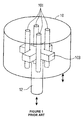
- FIG. 1 A prior art solution for preventing twisting of the column 12 relative to the shell 10 is shown in Fig. 1 .
- the top of the column is shown connected to a cross-shaped buffer 103 with vertical anti-rotational pipes 101 being located between the arm of the cross, at or close to their junction, to prevent rotation.
- Incorporating such restraining members adds to the complexity and cost of the design and still allows for some twisting along the column, if the anti rotation mechanism is only introduced at done at one end of the column.
- US 2002/0155767 A1 discloses a buoy with an actuating disc suspended beneath it on a spring via a column formed with a rack driving a pinion in response to relative motion of the disc and buoy.
- WO 03/058055 A1 discloses a stator arrangement fixed to the sea bed and having a non-circular interior surrounded by coils, in which a magnet is moved by a buoy on the water's surface to generate power.
- a WEC embodying the invention includes a shell and a column with a PTO device connected between the shell and the column.
- the shell and column are shaped such that, when placed in a body of water and in response to waves in the body of water, rotational and/or twisting motion between the shell and the column is inhibited while allowing vertical motion of the shell relative to the column.
- a main central column which is non-circular (i.e., it may be oblong or multi-sided) and which is positioned or fitted within the central opening of a shell which is shaped to contain the central column and prevent rotation or twisting.
- the non-circular inner wall of the shell is shaped to be complementary in structure to the non-circular outer wall of the column whereby the shell can not readily rotate relative to the column.
- the central column is a square column and the central opening of the shell is likewise square.
- This structure provides four plane surfaces, extending along the column, facing four corresponding plane surfaces extending along the inner wall of the shell. These opposing surfaces are parallel to each other and can be so maintained over a wide operating range, as the shell moves, up and down, relative to the column.
- a significant aspect of the inventive structure is that it facilitates the use of a PTO which includes a linear electric generator (LEG) system designed to produce electrical energy, directly, in response to the relative motion between the shell and the column.
- LEG linear electric generator
- the LEG system includes a permanent magnetic assembly (PMA) and an induction coil assembly (ICA) which perform better when formed between and along parallel surfaces whose dimensions and spacing can be maintained relatively constant. This feature aids to maintain good and efficient electromagnetic coupling of the components (PMA and ICA) of the LEG, ensuring more efficient operation.
- one of the PMA and ICA is located on, or in, or attached to, the shell and moves as the shell moves; and the other one of the PMA and ICA is located on, or attached to, the column and either moves as the column moves or remains stationary if the column is stationary.
- Relative motion between the shell and column when placed in a body of water and in response to waves in the body of water, causes the attached (or mounted) PMA and ICA assemblies to be driven, vertically, past each other, in response to motion of the waves, resulting in the generation of output voltages which are a function of the relative vertical motion while preventing rotational and twisting motion.
- the parallel surfaces provided by the shell's inner walls and the column's outer wall facilitate the incorporation of a guide and bearing system which maintains the relative alignment of the magnetic and induction coil assemblies and the spacing between them.
- the column may be multi-faceted (star shaped or spoke like) and the central opening of the shell may also be correspondingly multi-faceted to provide anti-rotational surfaces which can also be used for the placement of LEG components.
- a square elongated column 12 extending above the top 111 of a shell 10 and below the bottom 113 of the shell.
- the shell 10 has a central opening shaped to correspond in a complementary manner to the walls of the column to enable the column 12 to fit through the central opening of the shell 10, whereby the shell and column can move vertically, up and down, relative to each other, while preventing any rotational motion.
- the sides of the column (12a, 12b, 12c, 12d) define plane surfaces extending along the column.
- each side (12a, 12b, 12c, 12d) of the column is a side (103a, 103b, 103c, 103d) of the inner wall of the shell, each inner shell side defining a plane surface which is generally parallel to the corresponding side or face of the column.
- This structure enables the shell and column to slide past each other while allowing virtually no rotational movement between the shell and column.
- Fig. 2B is a partial top cross-sectional view of the square column 12 located within the central opening of the shell 10.
- Friction pads 17 are placed between the column and the inner wall 103 of the shell. The friction pads 17 ensure that the column can move smoothly up and down while maintaining a relatively constant spacing between the shell and the column.
- An induction coil assembly (ICA) 24c is shown attached along the inner wall 103c of the shell and a permanent magnetic assembly (PMA) 22c is shown attached to the outer wall 12c of the column 12.
- PMA 22c permanent magnetic assembly
- an ICA 24d is shown connected to the outer wall 12d of the column and a PMA 22d is shown attached to the inner wall 103d of the shell 10.
- one of a PMA and an ICA may be connected (attached or mounted) on one of the inner wall of the shell and outer wall of the column and the other one of the PMA and the ICA is connected (attached or mounted) to the other one of the inner wall of the shell and outer wall of the column.
- a PMA or ICA
- the plane surface of the column and the corresponding plane surface of the internal wall of the shell can be made to be parallel to each other for an extended length. This permits the PMA to pass along the coil assembly with a relatively well controlled gap over a predetermined length of travel, defining the operating range.
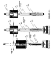
- Figs. 2C1, 2C2, 2C3 show WECs which are formed with a square column and a shell with a square central opening. These WECs may include one, or more, power take off (PTO) device which includes a linear electric generator (LEG) device 20 connected between the "shell” and the "spar".
- PTO power take off
- LEG linear electric generator
- Figure 2C1 shows a neutrally buoyant shell 10 typically submerged below the surface of the ocean with a tethered or anchored vertical column (spar) 12.
- Fig. 2C2 shows a buoyant shell typically floating at the surface of the ocean also with a tethered or anchored vertical column (spar)12.
- Fig. 2C3 illustrates a dual wave energy absorber where the shell 10 and the spar 12 move relative to each other, the shell generally in phase with the waves and the spar tending to move out of phase with the shell and/or the ocean waves.
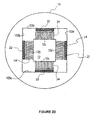
- Fig. 2D shows the four internal walls (103a, 103b, 103cc, 103d) of the shell 10 and the corresponding outer facets (12a, 12b, 12c, 12d) of the column 12.
- a permanent magnetic assembly (PMA) 22 may be attached to a wall of column and an induction coil assembly (ICA) 24 may be attached to the corresponding inner wall of the shell; or, alternatively, (b) an ICA may be attached to the column and a PMA may be attached to the corresponding inner wall of the shell.
- PMA permanent magnetic assembly
- ICA induction coil assembly
- Figure 2D shows a high-force, high-power LEG cross-section.
- the unit includes four LEG assemblies, each with a (moving) PMA 22 and a (stationary) stator ICA 24.
- the LEG is configured in a box configuration for two reasons. First, the large magnet-stator attractive force is somewhat negated if the magnets are held apart by a support structure. Second, the overall length of the quad-LEG may be made one-fourth the length of a single LEG. Other configurations may be considered. For example, the LEG may be implemented as one or more back-to-back magnet-stator assemblies.
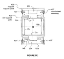
- FIG. 2E shows some of the details of the mounting of LEGs mounted on two sides of a square column.
- a PMA 22c is shown attached by means of a magnetic support plate 405 to the inner wall 103c of the shell.
- a corresponding ICA 24c (also referred to as a stator) is attached by means of a coil support plate 403 to the outer wall 12c of column 12.
- wheeled assemblies 407 are shown connected between the PMA and ICA support plates (403, 405) to enable: (a) smooth movement of the shell relative to the column; and (b) for maintaining the gap spacing between the components (shell and column and PMA and ICA) relatively constant over the full length of travel. The significance of this structure is further described below.
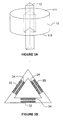
- Figures 3A and 3B show, respectively, a triangular column 12 mounted within a shell 10 having a corresponding central cut out and a partial cross section of the column and shaft showing permanent magnetic (22) and induction coil (24) assemblies.
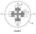
- Figure 4 shows that the outer surface of the column and the central portion of the shell may be cross-shaped to provide extensive parallel surfaces along which permanent magnetic and coil assemblies may be attached while at the same time providing a significant anti-rotational configuration.
- FIGs 2-4 illustrate the mounting of a LEG assembly on multi-sided column and shell structures which are designed to provide anti-rotation (i.e., to prevent rotation of the shell relative to the column) while simultaneously providing parallel surfaces between the shell and the column to enable the formation of a more efficient LEG;
- the central column of the WEC may be multi-sided (e.g., a square column having 4 sides), with the sides of the inner wall of the shell, facing the column, having faces parallel to each side of the central column, and that a LEG assembly may be located between each side of the central column and a corresponding face of the inner shell wall.
- Wave energy converters suitable for practicing the invention may include many different types of systems.
- any WEC which includes first and second structures (e.g., a shell and a spar) which, in response to forces such as those produced by ocean waves, move relative to each other may be suitable for practicing the invention.
- a PTO which includes a linear electric generator (LEG) 20, may be coupled between the first and second structures to convert their relative motion into electrical energy directly .
- LEG linear electric generator
- the PTO may be placed in many different locations, providing a high degree of freedom in the design of the physical configuration of the system.
- the invention may be used with any type of PTO, the use of a linear electric generator (LEG) is highly desirable as the WEC's power take-off (PTO) device for a number of reasons.
- LEG linear electric generator
- the projected efficiency of the all-electric system is estimated to be above 90% at rated force and velocity. This efficiency is well above the less than 80% efficiency of existing hydraulic-electric system.
- the hydraulic components are also expensive, have limited life and reliability, and present installation and maintenance challenges.
- a significant benefit of the LEG is that it enables implementation of significant improvement in efficiency and survivability features.
- One aspect of the invention is that it enables implementing an active impedance matching system (AIMS) which includes feeding back power to the buoy (WEC) during a portion of each wave cycle.
- AIMS active impedance matching system
- WEC buoy
- the life of a hydraulic motor, when operated as a pump, is shortened significantly.
- the LEG can be operated as a motor and/or as a generator, depending on the direction of current flow and applied mechanical force.
- the LEG enables active impedance matching, with a resultant increase in WEC efficiency.
- a LEG can also be configured with essentially unlimited stroke. This feature has enormous benefit in terms of WEC structural design and survivability.
- the impact forces not the wave forces, control the structural design.
- existing WECs have limited stroke, driven by the finite length of the hydraulic cylinder or other mechanical PTO devices, which requires a mechanical system with end stops and dampers to absorb the impact loads.
- the anchor, universal joint, and column must also be designed to handle these loads.
- the force on the structural components is limited to that exerted by the power take-off device (the LEG in this case).
- the power take-off device the LEG in this case
- passive damping With the addition of copper or aluminum plates at the end of normal power take-off stroke, passive damping (braking) can be implemented. This damping serves to take energy out of the buoy in storm conditions.
- the structural design of a WEC using LEG systems is greatly simplified.
- the WECs are intended to be placed in a body of water (e. g., an ocean) and the waves cause the shell 10 to move up and down relative to the central column (piston or spar) 12.
- the up and down motion of ocean waves applies a force to the shell 10, causing up and down motion of the shell relative to the spar 12 which may be a stationary member of the wave energy converter system.
- the spar 12 may also be a moving member, but whose movement tends to be out of phase with the motion of the shell.
- the LEG assemblies 20 normally include a permanent magnet (PM) assembly 22 and an induction coil assembly, 24.
- the permanent magnet assembly (PMA) 22 and the induction coil assembly (ICA) 24 need not be encased in a common sealed housing. Separately enclosed magnet and induction coil assemblies provide options not possible with known common-housing linear electric machines.
- the LEG assemblies can be placed above, below, on the inside or on the outside of a wave energy converter shell.
- the permanent magnets 22 are mechanically coupled to one of the shell 10 and column of the WEC and the induction coil assemblies 24 are affixed to the other one of the shell and column 12.
- the ICA and PMA assemblies (24, 22) are positioned relative to each other so that there is a small gap between them to ensure strong electromagnetic coupling between the coils and the magnets while allowing "unimpeded" physical linear (vertical) motion relative to each other. That is, relative movement is unimpeded except for the forces exerted due to the desired power generation and power extraction. In all configurations there is relative vertical movement between the coils and the magnets as the shell moves up and down. However, rotational or twisting movement is inhibited.
- the instant invention resolves a problem which exists in that there are twisting and turning forces between the shell 10 and the central column 12 tending to cause the shell to rotate relative to the column (or vice-versa).
- the central column 12 is shaped such that it has a multiplicity of sides (e.g., three or more sides) with the column mounted through the center of the shell and the inner wall or core section of the shell having a complementary structure to the sides of the column.
- the column could be made oblong (i.e., non-circular) and the central shell opening could be made with a complementary corresponding structure.
- the inner walls 103 of the shell 10 may be formed having parallel surfaces to the outer walls or sides of the column. For the "anti-rotational" type of design the tendency of the shell to rotate relative to the column has been significantly reduced, if not eliminated.
- parallel and facing (opposite) plane surfaces are formed which make it easier to position, locate and hold LEG assemblies.
- the ICA 24 can be mounted on one of the outer side(s) of the column 12 and the inner wall(s) 103 of the shell and the PMA 22 can be mounted on the other one of the outer side(s) of the column 12 and the inner wall(s) 103 of the shell.
- forming the LEG assemblies along parallel surfaces aids in the forming of LEG assemblies whose dimensions and movements are easier to control resulting in a more reliable and more efficient LEG.
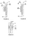
- Figs. 5A and 5B Different aspects of the configurations of the LEG 20 are shown in Figs. 5A and 5B .
- the PMA 22 is shown located along the column 12, (which is assumed to be, but need not be) stationary, while the ICA 24 is connected to the shell 10 and moves up and down across the PMA 22, as the shell 10 moves up and down relative to the shaft 12.
- an air gap (it could be a liquid gap) is maintained between the two assemblies, 22 and 24.
- the ICA 24 is shown located along the shaft 12 (which is assumed to be, but need not be, stationary), while the PMA 22 is connected to the shell 10 and moves up and down across the ICA 24, as the shell 10 moves up and down relative to the shaft 12.
- Fig. 5C shows a side view of the ICA 24 being propelled by the shell 10 across the PMA 22.
- wave action forces the shell to move up and down, causing relative motion between the induction coils and the permanent magnets.
- the coil and magnetic assemblies are designed to pass each other with the small "gap" between the assemblies being maintained relatively constant to ensure good electro-magnetic coupling at all times. In this way, mechanical force and motion are converted to electrical current and voltage in an efficient manner.
- each of the 4 sides of the column 12 is a LEG support assembly with a coil assembly 24 mounted on each LEG support 123. Opposite each coil assembly there is located a magnetic assembly 22 separated from the coil assembly by an air gap. Each magnetic assembly is mounted on a magnet backing plate which is attached to a LEG support.
- the individual LEG supports may be interconnected with an optional LEG out support to contain the leg assemblies.
- Figures 6A and 6B illustrate how the gap between the coil assembly and the magnetic assembly may be maintained over the relative long distances which the magnets and/or coils may have to travel relative to each other under adverse conditions. Two features of the design shown in these figures should be noted. (1) the magnets are divided into relatively small segments (e.g., 22a, 22b, 22c, etc...); and (2) the various segments are separated and supported by bearings, 401.
- the induction coil assemblies 24 are mounted on and supported by a coil support structure 403 which may be attached (or coupled) to a central column 12 or shell 10.
- the segmented magnetic assemblies 22a, b, c, are mounted on and supported by a magnet support structure 405 which may be attached to the shell 10 or the column 12.
- Bearings 401 function to hold the coil and magnet assemblies apart maintaining the desired gap distance between the two assemblies. At the same time, the bearings 401 also aid in the movement of the two assemblies relative to each other.
- the bearings 401 may be circular (wheels) to permit easy travel. A possible configuration is shown in Fig. 2E in which the wheels can ride on a rail.
- the manufacture of the gap maintaining structure is facilitated when the walls of the shell and column face and are parallel to each other.
- using the bearings 401 and segmenting the PMA enables the gap between the PMA and the ICa to be maintained even where the column is round and the walls of the shell and column are not plane parallel surfaces.
Landscapes
- Engineering & Computer Science (AREA)
- Power Engineering (AREA)
- Mechanical Engineering (AREA)
- Chemical & Material Sciences (AREA)
- Combustion & Propulsion (AREA)
- General Engineering & Computer Science (AREA)
- Transportation (AREA)
- Other Liquid Machine Or Engine Such As Wave Power Use (AREA)
- Linear Motors (AREA)
- Connection Of Motors, Electrical Generators, Mechanical Devices, And The Like (AREA)
- Reciprocating, Oscillating Or Vibrating Motors (AREA)
- Control Of Eletrric Generators (AREA)
- Braking Arrangements (AREA)
- Revetment (AREA)
- Electric Clocks (AREA)
- Electromechanical Clocks (AREA)
- Ac-Ac Conversion (AREA)
Description
- This application claims priority from provisional patent application Serial Number
60/553,666 - This invention relates to apparatus, systems and methods for converting energy present in ocean surface waves into electric energy.
- Known wave energy converter (WEC) systems for capturing ocean surface wave energy include: (a) a first component (also referred to herein as a "shell" or "vessel" or "float") which, when placed in a body of water, is designed to move up and down, generally, in phase with the waves in the water and thus absorb and/or release energy; (b) a second component (also referred to herein as a "shaft", "spar", "column" or piston) which is either stationary or moves generally out of phase relative to the waves and the first structure; and (c) a power take off (PTO) device coupled between the first and second components which, in response to the relative motion between the first and second structures, is designed to produce electrical energy.
- Due to the forces of the waves there tends to be twisting and turning (rotation) of the shell relative to the column when the WEC is in the water. That is, the body of water applies forces to the shell and column which tend to cause the shell to rotate or twist about the column (in addition to the desired vertical, up and down, motion). The twisting or rotational motion is potentially damaging and is highly undesirable.
- A prior art solution for preventing twisting of the
column 12 relative to theshell 10 is shown inFig. 1 . The top of the column is shown connected to across-shaped buffer 103 with verticalanti-rotational pipes 101 being located between the arm of the cross, at or close to their junction, to prevent rotation. Incorporating such restraining members adds to the complexity and cost of the design and still allows for some twisting along the column, if the anti rotation mechanism is only introduced at done at one end of the column. -
US 2002/0155767 A1 discloses a buoy with an actuating disc suspended beneath it on a spring via a column formed with a rack driving a pinion in response to relative motion of the disc and buoy.WO 03/058055 A1 - A WEC embodying the invention includes a shell and a column with a PTO device connected between the shell and the column. The shell and column are shaped such that, when placed in a body of water and in response to waves in the body of water, rotational and/or twisting motion between the shell and the column is inhibited while allowing vertical motion of the shell relative to the column.
- In systems embodying the invention, there is included a main central column which is non-circular (i.e., it may be oblong or multi-sided) and which is positioned or fitted within the central opening of a shell which is shaped to contain the central column and prevent rotation or twisting. The non-circular inner wall of the shell is shaped to be complementary in structure to the non-circular outer wall of the column whereby the shell can not readily rotate relative to the column.
- In a particular embodiment, the central column is a square column and the central opening of the shell is likewise square. This structure provides four plane surfaces, extending along the column, facing four corresponding plane surfaces extending along the inner wall of the shell. These opposing surfaces are parallel to each other and can be so maintained over a wide operating range, as the shell moves, up and down, relative to the column.
- A significant aspect of the inventive structure is that it facilitates the use of a PTO which includes a linear electric generator (LEG) system designed to produce electrical energy, directly, in response to the relative motion between the shell and the column. The LEG system includes a permanent magnetic assembly (PMA) and an induction coil assembly (ICA) which perform better when formed between and along parallel surfaces whose dimensions and spacing can be maintained relatively constant. This feature aids to maintain good and efficient electromagnetic coupling of the components (PMA and ICA) of the LEG, ensuring more efficient operation.
- Typically, in WECs including anti-rotational structures, one of the PMA and ICA is located on, or in, or attached to, the shell and moves as the shell moves; and the other one of the PMA and ICA is located on, or attached to, the column and either moves as the column moves or remains stationary if the column is stationary. Relative motion between the shell and column, when placed in a body of water and in response to waves in the body of water, causes the attached (or mounted) PMA and ICA assemblies to be driven, vertically, past each other, in response to motion of the waves, resulting in the generation of output voltages which are a function of the relative vertical motion while preventing rotational and twisting motion.
- The parallel surfaces provided by the shell's inner walls and the column's outer wall facilitate the incorporation of a guide and bearing system which maintains the relative alignment of the magnetic and induction coil assemblies and the spacing between them.
- The column may be multi-faceted (star shaped or spoke like) and the central opening of the shell may also be correspondingly multi-faceted to provide anti-rotational surfaces which can also be used for the placement of LEG components.
- In the accompanying drawings (which are not drawn to scale) like reference characters denote like components; and
-
FIGURE 1 is an illustrative diagram (not to scale) of a prior art structure for preventing the shell and column of a WEC from rotating relative to each other;Fig. 2A is a diagram illustrating the construction of an anti-rotational column and a corresponding float, in accordance with the invention; -
Figure 2B is a cross-sectional diagram illustrating the layout of an induction coil assembly and a permanent magnet assembly for the structure ofFig. 2A ; -
Figures 2C1, 2C2, 2C3 are diagrams of WECs with a square column and shells with square central openings, as per the invention; -
Figure 2D is a cross-section illustrating the positioning of induction coil and magnet assemblies along the outer plane surfaces of a column and the inner surfaces of a shell; -
Figure 2E is a diagram illustrating a mechanism for controlling the motion and spacing of the column and shell and the LEG attached to the WEC; -
Figure 3A is a diagram illustrating the construction of another anti-rotational column and a corresponding float in accordance with the invention; -
Figure 3B is a diagram illustrating the layout of an induction coil assembly and a permanent magnet assembly for the structure ofFig. 3A ; -
Figure 4 Is a diagram illustrating the construction of a cross shaped column and a corresponding cross shaped central shell opening in accordance with the invention; -
Figures 5A, 5B and 5C are highly simplified diagrams illustrating the layout of components of a LEG suitable for use in structures embodying the invention; andFigures 6A and 6B illustrate that the plane parallel surfaces of the shell and column formed in accordance with the invention facilitate maintaining the gap between the components of the LEG relatively constant. - Referring to
Fig. 2A there is shown a squareelongated column 12 extending above thetop 111 of ashell 10 and below thebottom 113 of the shell. Theshell 10 has a central opening shaped to correspond in a complementary manner to the walls of the column to enable thecolumn 12 to fit through the central opening of theshell 10, whereby the shell and column can move vertically, up and down, relative to each other, while preventing any rotational motion. As shown inFigs. 2A and2B , the sides of the column (12a, 12b, 12c, 12d) define plane surfaces extending along the column. Corresponding to each side (12a, 12b, 12c, 12d) of the column is a side (103a, 103b, 103c, 103d) of the inner wall of the shell, each inner shell side defining a plane surface which is generally parallel to the corresponding side or face of the column. This structure enables the shell and column to slide past each other while allowing virtually no rotational movement between the shell and column. -
Fig. 2B is a partial top cross-sectional view of thesquare column 12 located within the central opening of theshell 10.Friction pads 17 are placed between the column and theinner wall 103 of the shell. Thefriction pads 17 ensure that the column can move smoothly up and down while maintaining a relatively constant spacing between the shell and the column. An induction coil assembly (ICA) 24c is shown attached along theinner wall 103c of the shell and a permanent magnetic assembly (PMA) 22c is shown attached to theouter wall 12c of thecolumn 12. Alternatively, an ICA 24d is shown connected to theouter wall 12d of the column and aPMA 22d is shown attached to theinner wall 103d of theshell 10. Thus, one of a PMA and an ICA may be connected (attached or mounted) on one of the inner wall of the shell and outer wall of the column and the other one of the PMA and the ICA is connected (attached or mounted) to the other one of the inner wall of the shell and outer wall of the column. Thus, a PMA (or ICA) is attached to a portion of the column facing the internal shell wall 103i on which is mounted an ICA (PMA). The plane surface of the column and the corresponding plane surface of the internal wall of the shell can be made to be parallel to each other for an extended length. This permits the PMA to pass along the coil assembly with a relatively well controlled gap over a predetermined length of travel, defining the operating range. -
Figs. 2C1, 2C2, 2C3 show WECs which are formed with a square column and a shell with a square central opening. These WECs may include one, or more, power take off (PTO) device which includes a linear electric generator (LEG)device 20 connected between the "shell" and the "spar".Figure 2C1 shows a neutrallybuoyant shell 10 typically submerged below the surface of the ocean with a tethered or anchored vertical column (spar) 12.Fig. 2C2 shows a buoyant shell typically floating at the surface of the ocean also with a tethered or anchored vertical column (spar)12.Fig. 2C3 illustrates a dual wave energy absorber where theshell 10 and thespar 12 move relative to each other, the shell generally in phase with the waves and the spar tending to move out of phase with the shell and/or the ocean waves. -
Fig. 2D (like 2B) shows the four internal walls (103a, 103b, 103cc, 103d) of theshell 10 and the corresponding outer facets (12a, 12b, 12c, 12d) of thecolumn 12. Note that either: (a) a permanent magnetic assembly (PMA) 22 may be attached to a wall of column and an induction coil assembly (ICA) 24 may be attached to the corresponding inner wall of the shell; or, alternatively, (b) an ICA may be attached to the column and a PMA may be attached to the corresponding inner wall of the shell. -
Figure 2D shows a high-force, high-power LEG cross-section. The unit includes four LEG assemblies, each with a (moving)PMA 22 and a (stationary)stator ICA 24. The LEG is configured in a box configuration for two reasons. First, the large magnet-stator attractive force is somewhat negated if the magnets are held apart by a support structure. Second, the overall length of the quad-LEG may be made one-fourth the length of a single LEG. Other configurations may be considered. For example, the LEG may be implemented as one or more back-to-back magnet-stator assemblies. -
Figure 2E shows some of the details of the mounting of LEGs mounted on two sides of a square column. APMA 22c is shown attached by means of amagnetic support plate 405 to theinner wall 103c of the shell. A correspondingICA 24c (also referred to as a stator) is attached by means of acoil support plate 403 to theouter wall 12c ofcolumn 12. Infigure 2E wheeledassemblies 407 are shown connected between the PMA and ICA support plates (403, 405) to enable: (a) smooth movement of the shell relative to the column; and (b) for maintaining the gap spacing between the components (shell and column and PMA and ICA) relatively constant over the full length of travel. The significance of this structure is further described below. -
Figures 3A and 3B show, respectively, atriangular column 12 mounted within ashell 10 having a corresponding central cut out and a partial cross section of the column and shaft showing permanent magnetic (22) and induction coil (24) assemblies. -
Figure 4 shows that the outer surface of the column and the central portion of the shell may be cross-shaped to provide extensive parallel surfaces along which permanent magnetic and coil assemblies may be attached while at the same time providing a significant anti-rotational configuration. -
FIGs 2-4 illustrate the mounting of a LEG assembly on multi-sided column and shell structures which are designed to provide anti-rotation (i.e., to prevent rotation of the shell relative to the column) while simultaneously providing parallel surfaces between the shell and the column to enable the formation of a more efficient LEG; - The various figures illustrate that, in accordance with the invention, the central column of the WEC may be multi-sided (e.g., a square column having 4 sides), with the sides of the inner wall of the shell, facing the column, having faces parallel to each side of the central column, and that a LEG assembly may be located between each side of the central column and a corresponding face of the inner shell wall.
- Wave energy converters (WECs) suitable for practicing the invention may include many different types of systems. In general, any WEC which includes first and second structures (e.g., a shell and a spar) which, in response to forces such as those produced by ocean waves, move relative to each other may be suitable for practicing the invention. In accordance with the invention, a PTO, which includes a linear electric generator (LEG) 20, may be coupled between the first and second structures to convert their relative motion into electrical energy directly. Furthermore, in accordance with the invention, the PTO may be placed in many different locations, providing a high degree of freedom in the design of the physical configuration of the system.
- Although the invention may be used with any type of PTO, the use of a linear electric generator (LEG) is highly desirable as the WEC's power take-off (PTO) device for a number of reasons. The projected efficiency of the all-electric system is estimated to be above 90% at rated force and velocity. This efficiency is well above the less than 80% efficiency of existing hydraulic-electric system. The hydraulic components are also expensive, have limited life and reliability, and present installation and maintenance challenges.
- A significant benefit of the LEG is that it enables implementation of significant improvement in efficiency and survivability features. One aspect of the invention is that it enables implementing an active impedance matching system (AIMS) which includes feeding back power to the buoy (WEC) during a portion of each wave cycle. It has been found that using an hydraulic system for feed back is not possible on a long-term basis. The life of a hydraulic motor, when operated as a pump, is shortened significantly. The LEG, on the other hand, can be operated as a motor and/or as a generator, depending on the direction of current flow and applied mechanical force. Thus, the LEG enables active impedance matching, with a resultant increase in WEC efficiency.
- A LEG can also be configured with essentially unlimited stroke. This feature has enormous benefit in terms of WEC structural design and survivability. In existing WEC designs, the impact forces, not the wave forces, control the structural design. Also existing WECs have limited stroke, driven by the finite length of the hydraulic cylinder or other mechanical PTO devices, which requires a mechanical system with end stops and dampers to absorb the impact loads. The anchor, universal joint, and column must also be designed to handle these loads. In a system embodying the invention, without these end stops, the force on the structural components is limited to that exerted by the power take-off device (the LEG in this case). With the addition of copper or aluminum plates at the end of normal power take-off stroke, passive damping (braking) can be implemented. This damping serves to take energy out of the buoy in storm conditions. Thus, the structural design of a WEC using LEG systems is greatly simplified.
- Advantages of using linear electric generators (LEGs):
- 1- eliminate hydraulics or other mechanical translation devices - this should result in significant gain in efficiency since there are substantial power (efficiency) losses associated with hydraulic and mechanical translation conversion systems.
- 2- the cost of LEG systems should be cheaper than hydraulic pump/generator systems.
- 3- LEG gain in efficiency more reliable than hydraulic systems.
- 4- LEG systems allow for bi-directional power flow operation
- The WECs are intended to be placed in a body of water (e. g., an ocean) and the waves cause the
shell 10 to move up and down relative to the central column (piston or spar) 12. The up and down motion of ocean waves applies a force to theshell 10, causing up and down motion of the shell relative to thespar 12 which may be a stationary member of the wave energy converter system. Alternatively, thespar 12 may also be a moving member, but whose movement tends to be out of phase with the motion of the shell. - The
LEG assemblies 20 normally include a permanent magnet (PM)assembly 22 and an induction coil assembly, 24. In accordance with the invention, the permanent magnet assembly (PMA) 22 and the induction coil assembly (ICA) 24 need not be encased in a common sealed housing. Separately enclosed magnet and induction coil assemblies provide options not possible with known common-housing linear electric machines. The LEG assemblies can be placed above, below, on the inside or on the outside of a wave energy converter shell. Thepermanent magnets 22 are mechanically coupled to one of theshell 10 and column of the WEC and theinduction coil assemblies 24 are affixed to the other one of the shell andcolumn 12. - The ICA and PMA assemblies (24, 22) are positioned relative to each other so that there is a small gap between them to ensure strong electromagnetic coupling between the coils and the magnets while allowing "unimpeded" physical linear (vertical) motion relative to each other. That is, relative movement is unimpeded except for the forces exerted due to the desired power generation and power extraction. In all configurations there is relative vertical movement between the coils and the magnets as the shell moves up and down. However, rotational or twisting movement is inhibited.
- In general, the instant invention resolves a problem which exists in that there are twisting and turning forces between the
shell 10 and thecentral column 12 tending to cause the shell to rotate relative to the column (or vice-versa). In systems embodying the invention, thecentral column 12 is shaped such that it has a multiplicity of sides (e.g., three or more sides) with the column mounted through the center of the shell and the inner wall or core section of the shell having a complementary structure to the sides of the column. Instead of multiple sides the column could be made oblong (i.e., non-circular) and the central shell opening could be made with a complementary corresponding structure. Theinner walls 103 of theshell 10 may be formed having parallel surfaces to the outer walls or sides of the column. For the "anti-rotational" type of design the tendency of the shell to rotate relative to the column has been significantly reduced, if not eliminated. - Also, parallel and facing (opposite) plane surfaces are formed which make it easier to position, locate and hold LEG assemblies. The
ICA 24 can be mounted on one of the outer side(s) of thecolumn 12 and the inner wall(s) 103 of the shell and thePMA 22 can be mounted on the other one of the outer side(s) of thecolumn 12 and the inner wall(s) 103 of the shell. As discussed, forming the LEG assemblies along parallel surfaces aids in the forming of LEG assemblies whose dimensions and movements are easier to control resulting in a more reliable and more efficient LEG. - Different aspects of the configurations of the
LEG 20 are shown inFigs. 5A and 5B . InFig. 5A , thePMA 22 is shown located along thecolumn 12, (which is assumed to be, but need not be) stationary, while theICA 24 is connected to theshell 10 and moves up and down across thePMA 22, as theshell 10 moves up and down relative to theshaft 12. Note that an air gap (it could be a liquid gap) is maintained between the two assemblies, 22 and 24. InFig. 5B , theICA 24 is shown located along the shaft 12 (which is assumed to be, but need not be, stationary), while thePMA 22 is connected to theshell 10 and moves up and down across theICA 24, as theshell 10 moves up and down relative to theshaft 12. Note thatFig. 5C shows a side view of theICA 24 being propelled by theshell 10 across thePMA 22. - In configurations of interest, wave action forces the shell to move up and down, causing relative motion between the induction coils and the permanent magnets. Note that the coil and magnetic assemblies are designed to pass each other with the small "gap" between the assemblies being maintained relatively constant to ensure good electro-magnetic coupling at all times. In this way, mechanical force and motion are converted to electrical current and voltage in an efficient manner.
- For a configuration with a square column and a square central opening in the shell (e.g.,
Figs. 2B ,2C1 ,2D ), connected or mounted to each of the 4 sides of thecolumn 12 is a LEG support assembly with acoil assembly 24 mounted on each LEG support 123. Opposite each coil assembly there is located amagnetic assembly 22 separated from the coil assembly by an air gap. Each magnetic assembly is mounted on a magnet backing plate which is attached to a LEG support. The individual LEG supports may be interconnected with an optional LEG out support to contain the leg assemblies. - A problem exists in maintaining the "gap" distance between the induction coil assembly and the magnetic assembly relatively constant as the two assemblies passes each other. A problem also exists in the manufacture of long magnetic assemblies for use in the contemplated systems.
Figures 6A and 6B illustrate how the gap between the coil assembly and the magnetic assembly may be maintained over the relative long distances which the magnets and/or coils may have to travel relative to each other under adverse conditions. Two features of the design shown in these figures should be noted. (1) the magnets are divided into relatively small segments (e.g., 22a, 22b, 22c, etc...); and (2) the various segments are separated and supported by bearings, 401. This construction eliminates the need to form a long unitary magnetic assembly having precise measurements and eases the requirement that the very precise and small gap be maintained between the long unitary magnetic assembly and the induction coil assembly. InFigs. 6A and 6B theinduction coil assemblies 24 are mounted on and supported by acoil support structure 403 which may be attached (or coupled) to acentral column 12 orshell 10. The segmentedmagnetic assemblies 22a, b, c, are mounted on and supported by amagnet support structure 405 which may be attached to theshell 10 or thecolumn 12.Bearings 401 function to hold the coil and magnet assemblies apart maintaining the desired gap distance between the two assemblies. At the same time, thebearings 401 also aid in the movement of the two assemblies relative to each other. Thebearings 401 may be circular (wheels) to permit easy travel. A possible configuration is shown inFig. 2E in which the wheels can ride on a rail. - The manufacture of the gap maintaining structure is facilitated when the walls of the shell and column face and are parallel to each other. However, it should be appreciated that using the
bearings 401 and segmenting the PMA enables the gap between the PMA and the ICa to be maintained even where the column is round and the walls of the shell and column are not plane parallel surfaces.
Claims (8)
- A wave energy converter (WEC) comprising:a shell (10) being a floating body extending along the surface of a body of water and moving generally in phase with waves therein, anda non-circular column (12); said shell (10) and column (12) being spaced apart to permit the shell and column to move up and down relative to each other when placed in the body of water and in response to the waves present in said body of water; and a power take off (PTO) (22, 24) device connected between the shell and the column to convert the relative vertical motion between the shell and column due to the waves into electrical energy;characterized by:the shell having an outer wall and a central opening with a non-circular inner surface (103) shaped to conform to the non-circular outer surface of the column for the positioning therein and passing therethrough of said non-circular column, said non-circular column extending through the shell above and below the shell; and the said non-circular column positioned within, and extending along, the central opening of the shell, the non-circular inner surfaces of the shell and the non-circular outer surfaces of the column being formed and shaped such that, when placed in a body of water and in response to waves in the body of water, rotational and/or twisting motion between the shell and the column is inhibited while the inner surfaces of the shell and the outer surfaces of the column are spaced apart and extend along parallel spaced apart planes to permit unhindered vertical up and down motion of the shell relative to the column.
- A WEC as claimed in claim 1, wherein the PTO is a linear electric generator including a permanent magnetic assembly (PMA) (22) and an induction coil assembly (ICA) (24), the PMA being attached to one surface of the shell and column and the ICA being connected to an opposite facing surface of the other one of the shell and column for producing electric energy, directly, when the shell and column move vertically, up and down, relative to each other, along parallel spaced apart planes.
- A WEC as claimed in claim 1 wherein the column is a square column and the central opening of the shell is square; the sides of the columns defining plane surfaces parallel to plane surfaces of the central opening of the shell; and wherein friction pads (17) are positioned between the central opening of the shell and the column for maintaining the spacing between the shell and column when the shell and column move relative to each other and the friction pads enabling free movement of the shell and column in the vertical direction.
- A WEC as claimed in claim 3, wherein the PTO is a linear electric generator including a permanent magnetic assembly (PMA) (22) and an induction coil assembly (ICA) (24), the PMA being attached to side of one of the shell and column and the ICA being connected to a corresponding, facing, side of the other one of the shell and column for producing electric energy, directly, when the shell and column move vertically, up and down, relative to each other.
- A WEC as claimed in claim 4, further including means (401) positioned between the PMA and the ICA for establishing a gap between them and for maintaining the gap relatively constant as the shell and column move relative to each other, along parallel spaced apart planes.
- A WEC as claimed in claim 1 wherein the column is multi-sided and wherein the central opening of the shell is multi-sided in a corresponding manner to the column, each side of the column defining a plane surface extending along the column and each side of the shell defining a plane surface parallel to a corresponding side of the column.
- A WEC as claimed in claim 6, wherein the PTO is a linear electric generator including a permanent magnetic assembly (PMA) (22) and an induction coil assembly (ICA) (24), the PMA being attached to one surface of the shell and column and the ICA being connected to a corresponding surface of the other one of the shell and column for producing electric energy, directly, when the shell and column move vertically, up and down, relative to each other.
- A WEC as claimed in claim 7, further including means (401) positioned between the PMA and the ICA for establishing a gap between them and for maintaining the gap relatively constant as the shell and column move relative to each other.
Applications Claiming Priority (2)
| Application Number | Priority Date | Filing Date | Title |
|---|---|---|---|
| US55366604P | 2004-03-16 | 2004-03-16 | |
| PCT/US2005/008753 WO2005089379A2 (en) | 2004-03-16 | 2005-03-15 | Antirotational structure for wave energy converters |
Publications (3)
| Publication Number | Publication Date |
|---|---|
| EP1738071A2 EP1738071A2 (en) | 2007-01-03 |
| EP1738071A4 EP1738071A4 (en) | 2012-11-14 |
| EP1738071B1 true EP1738071B1 (en) | 2015-08-19 |
Family
ID=34994240
Family Applications (4)
| Application Number | Title | Priority Date | Filing Date |
|---|---|---|---|
| EP05725733.9A Expired - Lifetime EP1733141B1 (en) | 2004-03-16 | 2005-03-15 | Wave energy converters (wecs) with linear electric generators (legs). |
| EP05728147.9A Expired - Lifetime EP1725897B1 (en) | 2004-03-16 | 2005-03-15 | WAVE ENERGY CONVERTERS (WECs) WITH VELOCITY MULTIPLICATION |
| EP05725734.7A Expired - Lifetime EP1738071B1 (en) | 2004-03-16 | 2005-03-15 | Antirotational structure for wave energy converters |
| EP05730007.1A Expired - Lifetime EP1735175B1 (en) | 2004-03-16 | 2005-03-15 | Wave energy converter (wec) with magnetic braking |
Family Applications Before (2)
| Application Number | Title | Priority Date | Filing Date |
|---|---|---|---|
| EP05725733.9A Expired - Lifetime EP1733141B1 (en) | 2004-03-16 | 2005-03-15 | Wave energy converters (wecs) with linear electric generators (legs). |
| EP05728147.9A Expired - Lifetime EP1725897B1 (en) | 2004-03-16 | 2005-03-15 | WAVE ENERGY CONVERTERS (WECs) WITH VELOCITY MULTIPLICATION |
Family Applications After (1)
| Application Number | Title | Priority Date | Filing Date |
|---|---|---|---|
| EP05730007.1A Expired - Lifetime EP1735175B1 (en) | 2004-03-16 | 2005-03-15 | Wave energy converter (wec) with magnetic braking |
Country Status (9)
| Country | Link |
|---|---|
| US (3) | US7168532B2 (en) |
| EP (4) | EP1733141B1 (en) |
| JP (4) | JP4758983B2 (en) |
| AU (4) | AU2005222962B2 (en) |
| CA (4) | CA2536603C (en) |
| ES (4) | ES2558882T3 (en) |
| NO (4) | NO20061971L (en) |
| PT (2) | PT1738071E (en) |
| WO (4) | WO2005089295A2 (en) |
Families Citing this family (89)
| Publication number | Priority date | Publication date | Assignee | Title |
|---|---|---|---|---|
| GB0316869D0 (en) * | 2003-07-18 | 2003-08-20 | Kelly H P G | Method of operation for a self-protecting wave energy conversion plant |
| US7362003B2 (en) * | 2004-03-16 | 2008-04-22 | Ocean Power Technologies, Inc. | Coil switching circuit for linear electric generator |
| FR2872868A1 (en) * | 2004-07-06 | 2006-01-13 | Commissariat Energie Atomique | ENERGY RECOVERY DEVICE |
| US7352073B2 (en) * | 2004-06-28 | 2008-04-01 | Ames P Foerd | Ocean wave energy converter having an improved generator and ballast control |
| JP2006187079A (en) * | 2004-12-27 | 2006-07-13 | Hitachi Ltd | Cylindrical linear motor, electromagnetic suspension and vehicle using the same |
| US7323790B2 (en) * | 2005-03-15 | 2008-01-29 | Ocean Power Technologies, Inc. | Wave energy converters (WECs) with linear electric generators (LEGs) |
| US7339285B2 (en) * | 2006-01-12 | 2008-03-04 | Negron Crespo Jorge | Hydroelectric wave-energy conversion system |
| US7345372B2 (en) * | 2006-03-08 | 2008-03-18 | Perpetuum Ltd. | Electromechanical generator for, and method of, converting mechanical vibrational energy into electrical energy |
| US7420287B2 (en) * | 2006-03-28 | 2008-09-02 | Aleksandr Smushkovich | Intermittent force powered electromagnetic converters especially for sea waves |
| WO2007121382A2 (en) * | 2006-04-14 | 2007-10-25 | Ciiis, Llc | Power generator having a plurality of arranged power generator units |
| AU2007248730B2 (en) * | 2006-05-01 | 2014-02-06 | Ocean Power Technologies, Inc. | Improved wave energy converter (WEC) with heave plates |
| US7557456B2 (en) * | 2006-05-05 | 2009-07-07 | Sri International | Wave powered generation using electroactive polymers |
| US7538445B2 (en) * | 2006-05-05 | 2009-05-26 | Sri International | Wave powered generation |
| WO2008004854A1 (en) * | 2006-07-05 | 2008-01-10 | Ab Skf | Spring, assembly of spring and a damper, as well as a vehicle |
| US7476986B1 (en) * | 2006-08-07 | 2009-01-13 | Del Principe David M | Wave-action energy producing apparatus |
| DE102007015168A1 (en) * | 2007-03-27 | 2008-10-02 | Trithor Gmbh | Linear machine with a primary part and a secondary part |
| GB2439411B (en) * | 2007-04-27 | 2008-07-23 | Perpetuum Ltd | An electromechanical generator for converting mechanical vibrational energy into electrical energy |
| WO2008150817A1 (en) * | 2007-05-31 | 2008-12-11 | Artificial Muscle, Inc. | Optical systems employing compliant electroactive materials |
| WO2009006318A1 (en) | 2007-06-29 | 2009-01-08 | Artificial Muscle, Inc. | Electroactive polymer transducers for sensory feedback applications |
| US7554215B1 (en) * | 2007-07-03 | 2009-06-30 | Paul Caragine | Generator and method for generating electricity from subsurface currents |
| DE102007041128B4 (en) * | 2007-08-30 | 2011-12-29 | Schmidtsdorff Elektromotoren Reparaturwerk Und -Handel | oscillation generator |
| US20090079199A1 (en) * | 2007-09-25 | 2009-03-26 | Tubel Paulo S | Electric generator operated by reciprocating wellbore pump and monitoring system used therewith |
| JP4649668B2 (en) * | 2007-11-02 | 2011-03-16 | スミダコーポレーション株式会社 | Vibration type electromagnetic generator |
| ES2301443B1 (en) * | 2007-11-15 | 2009-08-25 | Acciona Energia, S.A. | WATER RESOURCES MEASUREMENT SYSTEM AT SEA, ENERGY PRODUCER AND INSTALLATION METHOD. |
| NO327758B1 (en) * | 2007-12-19 | 2009-09-14 | Quatro As | Device for absorbing wave power |
| DE102008021576A1 (en) * | 2008-04-30 | 2009-11-05 | Robert Bosch Gmbh | Hydraulic converter |
| US7785163B2 (en) * | 2008-08-15 | 2010-08-31 | Plasti-Fab Inc. | Wave energy buoy |
| CA2734602C (en) * | 2008-08-28 | 2016-01-05 | Seabased Ab | A wave-power unit, and a use of a such |
| DK176883B1 (en) * | 2008-09-19 | 2010-02-22 | Wavepiston Aps | Wave energy extraction apparatus |
| KR101082076B1 (en) * | 2008-10-08 | 2011-11-10 | 신익수 | Wave-power generating module, wave-power generating unit comprising the wave-power generating module, and wave-power generating apparatus comprising the wave-power generating unit |
| GB0821835D0 (en) | 2008-11-28 | 2009-01-07 | Trident Energy Ltd | Low cost linear generator wave energy converters |
| US7816797B2 (en) * | 2009-01-07 | 2010-10-19 | Oscilla Power Inc. | Method and device for harvesting energy from ocean waves |
| US8803346B2 (en) | 2009-03-09 | 2014-08-12 | Natural Power Concepts, Inc. | System and method for generating electricity using grid of wind and water energy capture devices |
| CA2725994C (en) * | 2009-03-30 | 2017-03-07 | Ocean Power Technologies, Inc. | Wec with improved power take off apparatus |
| EP2239793A1 (en) | 2009-04-11 | 2010-10-13 | Bayer MaterialScience AG | Electrically switchable polymer film structure and use thereof |
| GB2465642B (en) * | 2009-05-13 | 2010-11-10 | Wavebob Ltd | A wave energy conversion system |
| US20110057448A1 (en) * | 2009-09-08 | 2011-03-10 | Joseph Page | Wave energy converters |
| CA2745387C (en) * | 2009-11-23 | 2017-01-03 | Ocean Power Technologies, Inc. | Wave energy converter and power take off system |
| WO2012024000A1 (en) * | 2010-02-01 | 2012-02-23 | Oscilla Power Inc. | Wave energy harvester with improved performance |
| RU2413868C1 (en) * | 2010-03-16 | 2011-03-10 | Ильдар Фанилевич Мотыгуллин | Hydraulic-wave stock-type core electric generator |
| RU2413089C1 (en) * | 2010-03-16 | 2011-02-27 | Ильдар Фанилевич Мотыгуллин | Hydraulic wave rod core electric generator |
| JP4680317B2 (en) * | 2010-03-26 | 2011-05-11 | スミダコーポレーション株式会社 | Vibration type electromagnetic generator |
| BR112012030277B1 (en) * | 2010-05-28 | 2021-11-16 | Seabased Ab | LINEAR GENERATOR FOR SUBMERGED USE AND METHOD FOR ELECTRIC ENERGY PRODUCTION |
| KR101145084B1 (en) | 2010-06-03 | 2012-05-11 | 이형우 | Wave power generator |
| US7994651B2 (en) * | 2010-09-27 | 2011-08-09 | Dov Frishberg | Apparatus for converting the energy of waves on a body of water |
| US20120086205A1 (en) * | 2010-10-08 | 2012-04-12 | Balakrishnan Nair | Method and device for harvesting energy from ocean waves |
| GB2486279B (en) * | 2010-12-10 | 2013-11-06 | Trident Energy Ltd | Wave energy converter |
| EP2668679A4 (en) * | 2011-01-28 | 2015-08-12 | Oscilla Power Inc | Energy harvesting methods and devices, and applications thereof |
| WO2012118916A2 (en) | 2011-03-01 | 2012-09-07 | Bayer Materialscience Ag | Automated manufacturing processes for producing deformable polymer devices and films |
| TW201250288A (en) | 2011-03-22 | 2012-12-16 | Bayer Materialscience Ag | Electroactive polymer actuator lenticular system |
| US20140084727A1 (en) * | 2011-04-07 | 2014-03-27 | Cornell University | Electrical generator apparatus, system, method, and applications |
| US9255495B2 (en) * | 2011-08-24 | 2016-02-09 | Dresser-Rand Company | Magnetically-coupled damper for turbomachinery |
| US8810056B2 (en) | 2011-09-20 | 2014-08-19 | P. Foerd Ames | Ocean wave energy converter utilizing dual rotors |
| KR101635691B1 (en) * | 2011-11-11 | 2016-07-01 | 미쓰비시덴키 가부시키가이샤 | Cylindrical linear motor |
| JP5853659B2 (en) * | 2011-12-12 | 2016-02-09 | オムロン株式会社 | Power generation module |
| WO2013142552A1 (en) | 2012-03-21 | 2013-09-26 | Bayer Materialscience Ag | Roll-to-roll manufacturing processes for producing self-healing electroactive polymer devices |
| KR20150031285A (en) | 2012-06-18 | 2015-03-23 | 바이엘 인텔렉쳐 프로퍼티 게엠베하 | Stretch frame for stretching process |
| US9590193B2 (en) | 2012-10-24 | 2017-03-07 | Parker-Hannifin Corporation | Polymer diode |
| CA2871570C (en) | 2012-10-26 | 2018-02-20 | William Paul Sullivan | System and apparatus for generating electricity from motion of fluid |
| US10011910B2 (en) | 2012-10-29 | 2018-07-03 | Energystics, Ltd. | Linear faraday induction generator for the generation of electrical power from ocean wave kinetic energy and arrangements thereof |
| US8629572B1 (en) * | 2012-10-29 | 2014-01-14 | Reed E. Phillips | Linear faraday induction generator for the generation of electrical power from ocean wave kinetic energy and arrangements thereof |
| US9624900B2 (en) | 2012-10-29 | 2017-04-18 | Energystics, Ltd. | Linear faraday induction generator for the generation of electrical power from ocean wave kinetic energy and arrangements thereof |
| JP5667149B2 (en) * | 2012-11-08 | 2015-02-12 | 網矢 貞幸 | Wave generator |
| US8723353B1 (en) * | 2012-11-21 | 2014-05-13 | Barrie Franklin | Wave energy converter design incorporating an induction generator |
| DE102013201716B4 (en) * | 2013-02-01 | 2015-06-03 | Sinn Power Gmbh | LINEAR GENERATOR AND LINEAR DRIVE |
| CN104131951A (en) * | 2013-05-02 | 2014-11-05 | 罗才德 | Ocean power generation ship |
| CN103485972B (en) * | 2013-10-09 | 2016-02-03 | 东南大学 | A kind of tidal current wave power generation device |
| FR3016755B1 (en) * | 2014-01-17 | 2017-11-24 | Save Ingenierie | METHOD FOR MANAGING AN ELECTROMAGNETIC MACHINE FOR MODIFYING THE TOPOLOGY OF A CIRCUIT OF INDUCTIONS OF SAID MACHINE |
| US20160186715A1 (en) * | 2014-01-20 | 2016-06-30 | Mitchell Fait | Buoy for obtaining energy from a wave in a body of water |
| JP6344942B2 (en) * | 2014-03-27 | 2018-06-20 | 三輪精機株式会社 | Cabylt equipment |
| US9853529B2 (en) | 2014-04-29 | 2017-12-26 | Ishwar Ram Singh | Linear induction generator using magnetic repulsion |
| US9435316B2 (en) * | 2014-10-16 | 2016-09-06 | Industrial Technology Research Institute | Wave power generation system and motion control module thereof |
| GB2545612B (en) | 2014-10-22 | 2021-05-19 | Helder Da Costa Goncalves | Ozone with plasma sterilization/disinfection process and device |
| US9331548B1 (en) * | 2014-12-09 | 2016-05-03 | Mohammed Al Mattar | Devices and systems for generating sustainable energy from traffic |
| WO2017189455A1 (en) * | 2016-04-24 | 2017-11-02 | The Regents Of The University Of California | Submerged wave energy converter for shallow and deep water operations |
| WO2017205970A1 (en) * | 2016-05-30 | 2017-12-07 | Singh Ishwar Ram | Linear induction generator using magnetic repulsion |
| US10352290B2 (en) * | 2017-02-14 | 2019-07-16 | The Texas A&M University System | Method and apparatus for wave energy conversion |
| CN106877572B (en) * | 2017-04-13 | 2018-10-23 | 江苏科技大学 | A kind of tension membrane type wave energy generating set |
| US11002243B2 (en) | 2017-04-24 | 2021-05-11 | The Regents Of The University Of California | Submerged wave energy converter for deep water operations |
| DK179738B1 (en) | 2017-10-11 | 2019-04-30 | Ravn Niels | Wind-Driven Energy Converting Device |
| US10047717B1 (en) | 2018-02-05 | 2018-08-14 | Energystics, Ltd. | Linear faraday induction generator for the generation of electrical power from ocean wave kinetic energy and arrangements thereof |
| GB2572351B (en) * | 2018-03-27 | 2020-08-26 | Perpetuum Ltd | An electromechanical generator for converting mechanical vibrational energy into electrical energy |
| US10720956B2 (en) * | 2018-09-06 | 2020-07-21 | Intel Corporation | Low loss transmitter receiver switch with transformer matching network |
| JP6964639B2 (en) * | 2019-10-02 | 2021-11-10 | 本田技研工業株式会社 | Electric suspension device |
| JP7054714B2 (en) * | 2020-02-17 | 2022-04-14 | 本田技研工業株式会社 | Electric suspension device |
| CN112737213B (en) * | 2021-01-18 | 2022-04-15 | Oppo广东移动通信有限公司 | Electronic equipment and its power supply |
| IT202100016361A1 (en) * | 2021-06-22 | 2022-12-22 | Alberto Roncan | APPLIANCE FOR GENERATION OF ELECTRICITY WITH IMPROVED EFFICIENCY |
| WO2025054673A1 (en) * | 2023-09-15 | 2025-03-20 | D-Spar Technologies Pty Ltd | Wave energy conversion apparatus and methods of use thereof |
| CN117386548B (en) * | 2023-11-27 | 2024-02-27 | 华南理工大学 | A kinetic energy recovery wind and wave integrated system |
Family Cites Families (46)
| Publication number | Priority date | Publication date | Assignee | Title |
|---|---|---|---|---|
| US852232A (en) * | 1906-11-20 | 1907-04-30 | Ernest Kohler | Wave-motor. |
| US1223184A (en) * | 1916-07-11 | 1917-04-17 | August Victor Larson | Wave-motor. |
| US1244309A (en) * | 1916-09-14 | 1917-10-23 | William Clay Fox | Wave-motor. |
| US2962463A (en) * | 1958-07-14 | 1960-11-29 | Union Carbide Corp | Composition comprising styrene-acrylonitrile copolymer, plasticizer and wax and method of preparing same |
| US3362336A (en) * | 1965-10-23 | 1968-01-09 | Robert S. Kafka | Wave motion operated device |
| US3546473A (en) * | 1969-02-24 | 1970-12-08 | Alan H Rich | Oceanographic generator |
| FR2050601A5 (en) * | 1969-06-18 | 1971-04-02 | Elf Entr Rech Activit | |
| GB1316950A (en) | 1969-06-30 | 1973-05-16 | Univ North Wales | Electric generator |
| US3996176A (en) * | 1972-03-08 | 1976-12-07 | Zareh Lorenian | Method of manufacturing shaped members of synthetic thermoplastic materials free of softeners |
| US3918261A (en) * | 1974-04-10 | 1975-11-11 | Vernon Bailey | Wave and tide motor |
| US3970415A (en) * | 1975-04-10 | 1976-07-20 | Kaj Widecrantz | One way valve pressure pump turbine generator station |
| FR2319015A2 (en) * | 1975-07-22 | 1977-02-18 | Tintillier Jean Claude | Internal combustion engine generating electrical power directly - has coils attached to piston generating current in stator coil |
| US4260901A (en) * | 1979-02-26 | 1981-04-07 | Woodbridge David D | Wave operated electrical generation system |
| JPS55125364A (en) * | 1979-03-22 | 1980-09-27 | Yasuhiro Manabe | Power generator with use of vertical movement of wave |
| FR2480860A1 (en) * | 1980-04-22 | 1981-10-23 | Notari Mario | Energy recovery system using wave power - includes large pivoting plate moving linear electromagnetic generators as waves rise and fall |
| US4378178A (en) * | 1980-09-29 | 1983-03-29 | Roach Richard T | Offshore platform system and method |
| US4363213A (en) * | 1981-03-11 | 1982-12-14 | Paleologos George E | Combined body and power generating system |
| JPS57183263A (en) * | 1981-05-07 | 1982-11-11 | Fujitsu Ltd | Linear induction motor with magnetically stopping positioning function of secondary conductor |
| DE3314335A1 (en) * | 1983-04-20 | 1984-10-31 | Tillmann 6108 Weiterstadt Freudenberg | ENGINE MOUNT |
| US4539485A (en) * | 1983-10-07 | 1985-09-03 | Neuenschwander Victor L | Wave activated generator |
| JP2518206B2 (en) * | 1986-04-21 | 1996-07-24 | 株式会社安川電機 | Winding method of brushless DC linear motor |
| PH25051A (en) * | 1988-01-26 | 1991-01-28 | Lawrence C Burton | Wave energy system |
| JPH03179170A (en) * | 1989-12-07 | 1991-08-05 | Kumagai Gumi Co Ltd | Wave generating set |
| JPH0467762A (en) * | 1990-07-04 | 1992-03-03 | Ricoh Co Ltd | linear dc motor |
| JPH04155903A (en) * | 1990-10-19 | 1992-05-28 | Shin Etsu Chem Co Ltd | Magnetic circuit for magnetic levitation using permanent magnet |
| US5167786A (en) * | 1991-01-25 | 1992-12-01 | Eberle William J | Wave-power collection apparatus |
| JP2751684B2 (en) * | 1991-08-26 | 1998-05-18 | 神鋼電機株式会社 | Linear motor stator |
| US5347186A (en) * | 1992-05-26 | 1994-09-13 | Mcq Associates, Inc. | Linear motion electric power generator |
| JPH06280733A (en) * | 1993-03-24 | 1994-10-04 | Taiyo Plant Kk | Electromagnetic induction type wave activated power generating set |
| DE4338103A1 (en) * | 1993-11-08 | 1995-05-11 | Wolf Klemm | Device for obtaining electric energy (power) with the aid of the kinetic energy of water waves |
| JP3278665B2 (en) * | 1995-02-13 | 2002-04-30 | ミネベア株式会社 | Linear pulse motor |
| US5710464A (en) * | 1996-01-17 | 1998-01-20 | Kao; I. Nan | Power drive system for converting natural potential energy into a driving power to drive a power generator |
| SE508308C2 (en) * | 1996-04-29 | 1998-09-21 | Ips Interproject Service Ab | wave energy converters |
| JPH11205911A (en) * | 1998-01-07 | 1999-07-30 | Nkk Corp | Method for transporting multiple traveling bodies in a linear traveling device |
| GB9916779D0 (en) * | 1999-07-16 | 1999-09-15 | Kelly H P G | Sea wave to electrical energy conversion plant |
| GB9916778D0 (en) * | 1999-07-16 | 1999-09-15 | Kelly H P G | Safeguarding wave to electrical power generating apparatus |
| IES20000493A2 (en) * | 2000-06-16 | 2002-02-06 | Wavebob Ltd | Wave energy converter |
| US6328539B1 (en) * | 2000-06-30 | 2001-12-11 | Sheng Hu Hung | Hydraulic device powered by wave |
| KR100416923B1 (en) * | 2001-04-20 | 2004-01-31 | 주식회사 신성기연 | Buoy having self generating device of electricity using power of waves |
| US6515375B1 (en) * | 2001-07-25 | 2003-02-04 | The United States Of America As Represented By The Secretary Of The Navy | Adaptive wave motion electrical power generator |
| JP4732690B2 (en) * | 2002-01-10 | 2011-07-27 | スウェディッシュ シーベイスト エナジー アクチボラグ | Wave power device, use of wave power device for power generation, power generation method, and set of components for manufacturing linear generator for wave power device |
| US6791206B1 (en) * | 2002-06-14 | 2004-09-14 | David D. Woodbridge | Method for making a stabilized energy conversion operating platform |
| US6791205B2 (en) * | 2002-09-27 | 2004-09-14 | Aqua Magnetics, Inc. | Reciprocating generator wave power buoy |
| US7140180B2 (en) * | 2003-01-22 | 2006-11-28 | Ocean Power Technologies, Inc. | Wave energy converter (WEC) device and system |
| SE523000C2 (en) * | 2003-03-27 | 2004-03-23 | Swedish Seabased Energy Ab | Wave power unit |
| US7199481B2 (en) * | 2003-11-07 | 2007-04-03 | William Walter Hirsch | Wave energy conversion system |
-
2005
- 2005-03-15 AU AU2005222962A patent/AU2005222962B2/en not_active Ceased
- 2005-03-15 JP JP2007504063A patent/JP4758983B2/en not_active Expired - Fee Related
- 2005-03-15 WO PCT/US2005/008495 patent/WO2005089295A2/en not_active Ceased
- 2005-03-15 EP EP05725733.9A patent/EP1733141B1/en not_active Expired - Lifetime
- 2005-03-15 US US11/080,581 patent/US7168532B2/en not_active Expired - Fee Related
- 2005-03-15 US US11/080,319 patent/US7141888B2/en not_active Expired - Lifetime
- 2005-03-15 EP EP05728147.9A patent/EP1725897B1/en not_active Expired - Lifetime
- 2005-03-15 AU AU2005222973A patent/AU2005222973B2/en not_active Ceased
- 2005-03-15 AU AU2005223056A patent/AU2005223056B2/en not_active Ceased
- 2005-03-15 JP JP2007504062A patent/JP4994221B2/en not_active Expired - Fee Related
- 2005-03-15 CA CA2536603A patent/CA2536603C/en not_active Expired - Fee Related
- 2005-03-15 JP JP2007504006A patent/JP4870069B2/en not_active Expired - Fee Related
- 2005-03-15 CA CA2536598A patent/CA2536598C/en not_active Expired - Fee Related
- 2005-03-15 ES ES05725733.9T patent/ES2558882T3/en not_active Expired - Lifetime
- 2005-03-15 JP JP2007504015A patent/JP4860601B2/en not_active Expired - Fee Related
- 2005-03-15 AU AU2005223057A patent/AU2005223057B2/en not_active Ceased
- 2005-03-15 PT PT57257347T patent/PT1738071E/en unknown
- 2005-03-15 PT PT57257339T patent/PT1733141E/en unknown
- 2005-03-15 CA CA2537111A patent/CA2537111C/en not_active Expired - Fee Related
- 2005-03-15 WO PCT/US2005/008752 patent/WO2005089378A2/en not_active Ceased
- 2005-03-15 EP EP05725734.7A patent/EP1738071B1/en not_active Expired - Lifetime
- 2005-03-15 WO PCT/US2005/008753 patent/WO2005089379A2/en not_active Ceased
- 2005-03-15 EP EP05730007.1A patent/EP1735175B1/en not_active Expired - Lifetime
- 2005-03-15 ES ES05725734.7T patent/ES2553727T3/en not_active Expired - Lifetime
- 2005-03-15 ES ES05728147.9T patent/ES2565454T3/en not_active Expired - Lifetime
- 2005-03-15 US US11/080,718 patent/US7310944B2/en not_active Expired - Fee Related
- 2005-03-15 ES ES05730007T patent/ES2904287T3/en not_active Expired - Lifetime
- 2005-03-15 WO PCT/US2005/008469 patent/WO2005089284A2/en not_active Ceased
- 2005-03-15 CA CA2537110A patent/CA2537110C/en not_active Expired - Fee Related
-
2006
- 2006-05-03 NO NO20061971A patent/NO20061971L/en not_active Application Discontinuation
- 2006-05-03 NO NO20061973A patent/NO20061973L/en not_active Application Discontinuation
- 2006-05-03 NO NO20061961A patent/NO20061961L/en not_active Application Discontinuation
- 2006-05-03 NO NO20061969A patent/NO20061969L/en not_active Application Discontinuation
Also Published As
Similar Documents
| Publication | Publication Date | Title |
|---|---|---|
| CA2537111C (en) | Antirotational structures for wave energy converters | |
| US7323790B2 (en) | Wave energy converters (WECs) with linear electric generators (LEGs) | |
| US6791205B2 (en) | Reciprocating generator wave power buoy | |
| US6020653A (en) | Submerged reciprocating electric generator | |
| EP2577047B1 (en) | A linear generator for submerged use and a method of producing electric energy | |
| CN102966484A (en) | System for generating electricity from fluid currents | |
| EP3355449A1 (en) | Electrical machine for submerged applications | |
| US9581128B2 (en) | Systems and methods for wave energy conversion | |
| HUE026324T2 (en) | Electric machine having a low-mass design in magnetically active parts | |
| EP2577849B1 (en) | Stator frame for a submerged linear generator | |
| CN105422375B (en) | The seawave power generation machine platform of composite rotating wind-power electricity generation and flywheel energy storage function | |
| CN114731092A (en) | Electric power generator | |
| CN119844277B (en) | Offshore power generation platform | |
| WO2005103485A1 (en) | Reciprocating generator wave power buoy | |
| CN101572519A (en) | Magnetic energy power machine | |
| CN120332089A (en) | An offshore integrated power generation platform with auxiliary starting function |
Legal Events
| Date | Code | Title | Description |
|---|---|---|---|
| PUAI | Public reference made under article 153(3) epc to a published international application that has entered the european phase |
Free format text: ORIGINAL CODE: 0009012 |
|
| 17P | Request for examination filed |
Effective date: 20061016 |
|
| AK | Designated contracting states |
Kind code of ref document: A2 Designated state(s): AT BE BG CH CY CZ DE DK EE ES FI FR GB GR HU IE IS IT LI LT LU MC NL PL PT RO SE SI SK TR |
|
| AX | Request for extension of the european patent |
Extension state: AL BA HR LV MK YU |
|
| DAX | Request for extension of the european patent (deleted) | ||
| A4 | Supplementary search report drawn up and despatched |
Effective date: 20121015 |
|
| RIC1 | Information provided on ipc code assigned before grant |
Ipc: F03B 13/18 20060101ALI20121009BHEP Ipc: H02P 3/22 20060101ALI20121009BHEP Ipc: H02K 7/18 20060101ALI20121009BHEP Ipc: F03B 13/20 20060101AFI20121009BHEP Ipc: B60L 7/00 20060101ALI20121009BHEP Ipc: H02K 35/02 20060101ALI20121009BHEP |
|
| 17Q | First examination report despatched |
Effective date: 20130128 |
|
| REG | Reference to a national code |
Ref country code: DE Ref legal event code: R079 Ref document number: 602005047280 Country of ref document: DE Free format text: PREVIOUS MAIN CLASS: F03B0013100000 Ipc: F03B0013200000 |
|
| RIC1 | Information provided on ipc code assigned before grant |
Ipc: F03B 13/18 20060101ALI20141219BHEP Ipc: H02K 7/18 20060101ALI20141219BHEP Ipc: H02K 35/02 20060101ALI20141219BHEP Ipc: F03B 13/20 20060101AFI20141219BHEP Ipc: H02P 9/00 20060101ALI20141219BHEP Ipc: B60L 7/00 20060101ALI20141219BHEP Ipc: H02P 3/22 20060101ALI20141219BHEP Ipc: H02P 25/18 20060101ALI20141219BHEP |
|
| GRAP | Despatch of communication of intention to grant a patent |
Free format text: ORIGINAL CODE: EPIDOSNIGR1 |
|
| INTG | Intention to grant announced |
Effective date: 20150306 |
|
| GRAS | Grant fee paid |
Free format text: ORIGINAL CODE: EPIDOSNIGR3 |
|
| GRAA | (expected) grant |
Free format text: ORIGINAL CODE: 0009210 |
|
| AK | Designated contracting states |
Kind code of ref document: B1 Designated state(s): AT BE BG CH CY CZ DE DK EE ES FI FR GB GR HU IE IS IT LI LT LU MC NL PL PT RO SE SI SK TR |
|
| REG | Reference to a national code |
Ref country code: GB Ref legal event code: FG4D |
|
| REG | Reference to a national code |
Ref country code: CH Ref legal event code: EP |
|
| REG | Reference to a national code |
Ref country code: IE Ref legal event code: FG4D |
|
| REG | Reference to a national code |
Ref country code: AT Ref legal event code: REF Ref document number: 744020 Country of ref document: AT Kind code of ref document: T Effective date: 20150915 |
|
| REG | Reference to a national code |
Ref country code: DE Ref legal event code: R096 Ref document number: 602005047280 Country of ref document: DE |
|
| REG | Reference to a national code |
Ref country code: PT Ref legal event code: SC4A Free format text: AVAILABILITY OF NATIONAL TRANSLATION Effective date: 20151118 |
|
| REG | Reference to a national code |
Ref country code: ES Ref legal event code: FG2A Ref document number: 2553727 Country of ref document: ES Kind code of ref document: T3 Effective date: 20151211 |
|
| REG | Reference to a national code |
Ref country code: AT Ref legal event code: MK05 Ref document number: 744020 Country of ref document: AT Kind code of ref document: T Effective date: 20150819 |
|
| REG | Reference to a national code |
Ref country code: LT Ref legal event code: MG4D |
|
| REG | Reference to a national code |
Ref country code: NL Ref legal event code: MP Effective date: 20150819 |
|
| PG25 | Lapsed in a contracting state [announced via postgrant information from national office to epo] |
Ref country code: FI Free format text: LAPSE BECAUSE OF FAILURE TO SUBMIT A TRANSLATION OF THE DESCRIPTION OR TO PAY THE FEE WITHIN THE PRESCRIBED TIME-LIMIT Effective date: 20150819 Ref country code: LT Free format text: LAPSE BECAUSE OF FAILURE TO SUBMIT A TRANSLATION OF THE DESCRIPTION OR TO PAY THE FEE WITHIN THE PRESCRIBED TIME-LIMIT Effective date: 20150819 Ref country code: GR Free format text: LAPSE BECAUSE OF FAILURE TO SUBMIT A TRANSLATION OF THE DESCRIPTION OR TO PAY THE FEE WITHIN THE PRESCRIBED TIME-LIMIT Effective date: 20151120 |
|
| PG25 | Lapsed in a contracting state [announced via postgrant information from national office to epo] |
Ref country code: IS Free format text: LAPSE BECAUSE OF FAILURE TO SUBMIT A TRANSLATION OF THE DESCRIPTION OR TO PAY THE FEE WITHIN THE PRESCRIBED TIME-LIMIT Effective date: 20151219 Ref country code: SE Free format text: LAPSE BECAUSE OF FAILURE TO SUBMIT A TRANSLATION OF THE DESCRIPTION OR TO PAY THE FEE WITHIN THE PRESCRIBED TIME-LIMIT Effective date: 20150819 Ref country code: AT Free format text: LAPSE BECAUSE OF FAILURE TO SUBMIT A TRANSLATION OF THE DESCRIPTION OR TO PAY THE FEE WITHIN THE PRESCRIBED TIME-LIMIT Effective date: 20150819 Ref country code: PL Free format text: LAPSE BECAUSE OF FAILURE TO SUBMIT A TRANSLATION OF THE DESCRIPTION OR TO PAY THE FEE WITHIN THE PRESCRIBED TIME-LIMIT Effective date: 20150819 |
|
| PG25 | Lapsed in a contracting state [announced via postgrant information from national office to epo] |
Ref country code: NL Free format text: LAPSE BECAUSE OF FAILURE TO SUBMIT A TRANSLATION OF THE DESCRIPTION OR TO PAY THE FEE WITHIN THE PRESCRIBED TIME-LIMIT Effective date: 20150819 |
|
| REG | Reference to a national code |
Ref country code: FR Ref legal event code: PLFP Year of fee payment: 12 |
|
| PG25 | Lapsed in a contracting state [announced via postgrant information from national office to epo] |
Ref country code: SK Free format text: LAPSE BECAUSE OF FAILURE TO SUBMIT A TRANSLATION OF THE DESCRIPTION OR TO PAY THE FEE WITHIN THE PRESCRIBED TIME-LIMIT Effective date: 20150819 Ref country code: EE Free format text: LAPSE BECAUSE OF FAILURE TO SUBMIT A TRANSLATION OF THE DESCRIPTION OR TO PAY THE FEE WITHIN THE PRESCRIBED TIME-LIMIT Effective date: 20150819 Ref country code: IT Free format text: LAPSE BECAUSE OF FAILURE TO SUBMIT A TRANSLATION OF THE DESCRIPTION OR TO PAY THE FEE WITHIN THE PRESCRIBED TIME-LIMIT Effective date: 20150819 Ref country code: CZ Free format text: LAPSE BECAUSE OF FAILURE TO SUBMIT A TRANSLATION OF THE DESCRIPTION OR TO PAY THE FEE WITHIN THE PRESCRIBED TIME-LIMIT Effective date: 20150819 Ref country code: DK Free format text: LAPSE BECAUSE OF FAILURE TO SUBMIT A TRANSLATION OF THE DESCRIPTION OR TO PAY THE FEE WITHIN THE PRESCRIBED TIME-LIMIT Effective date: 20150819 |
|
| REG | Reference to a national code |
Ref country code: DE Ref legal event code: R097 Ref document number: 602005047280 Country of ref document: DE |
|
| PG25 | Lapsed in a contracting state [announced via postgrant information from national office to epo] |
Ref country code: RO Free format text: LAPSE BECAUSE OF FAILURE TO SUBMIT A TRANSLATION OF THE DESCRIPTION OR TO PAY THE FEE WITHIN THE PRESCRIBED TIME-LIMIT Effective date: 20150819 |
|
| PLBE | No opposition filed within time limit |
Free format text: ORIGINAL CODE: 0009261 |
|
| STAA | Information on the status of an ep patent application or granted ep patent |
Free format text: STATUS: NO OPPOSITION FILED WITHIN TIME LIMIT |
|
| 26N | No opposition filed |
Effective date: 20160520 |
|
| PG25 | Lapsed in a contracting state [announced via postgrant information from national office to epo] |
Ref country code: SI Free format text: LAPSE BECAUSE OF FAILURE TO SUBMIT A TRANSLATION OF THE DESCRIPTION OR TO PAY THE FEE WITHIN THE PRESCRIBED TIME-LIMIT Effective date: 20150819 Ref country code: BE Free format text: LAPSE BECAUSE OF NON-PAYMENT OF DUE FEES Effective date: 20160331 |
|
| REG | Reference to a national code |
Ref country code: DE Ref legal event code: R119 Ref document number: 602005047280 Country of ref document: DE |
|
| PG25 | Lapsed in a contracting state [announced via postgrant information from national office to epo] |
Ref country code: LU Free format text: LAPSE BECAUSE OF FAILURE TO SUBMIT A TRANSLATION OF THE DESCRIPTION OR TO PAY THE FEE WITHIN THE PRESCRIBED TIME-LIMIT Effective date: 20160315 Ref country code: MC Free format text: LAPSE BECAUSE OF FAILURE TO SUBMIT A TRANSLATION OF THE DESCRIPTION OR TO PAY THE FEE WITHIN THE PRESCRIBED TIME-LIMIT Effective date: 20150819 |
|
| REG | Reference to a national code |
Ref country code: CH Ref legal event code: PL |
|
| REG | Reference to a national code |
Ref country code: IE Ref legal event code: MM4A |
|
| PG25 | Lapsed in a contracting state [announced via postgrant information from national office to epo] |
Ref country code: BE Free format text: LAPSE BECAUSE OF FAILURE TO SUBMIT A TRANSLATION OF THE DESCRIPTION OR TO PAY THE FEE WITHIN THE PRESCRIBED TIME-LIMIT Effective date: 20150819 |
|
| PG25 | Lapsed in a contracting state [announced via postgrant information from national office to epo] |
Ref country code: CH Free format text: LAPSE BECAUSE OF NON-PAYMENT OF DUE FEES Effective date: 20160331 Ref country code: IE Free format text: LAPSE BECAUSE OF NON-PAYMENT OF DUE FEES Effective date: 20160315 Ref country code: DE Free format text: LAPSE BECAUSE OF NON-PAYMENT OF DUE FEES Effective date: 20161001 Ref country code: LI Free format text: LAPSE BECAUSE OF NON-PAYMENT OF DUE FEES Effective date: 20160331 |
|
| REG | Reference to a national code |
Ref country code: FR Ref legal event code: PLFP Year of fee payment: 13 |
|
| REG | Reference to a national code |
Ref country code: FR Ref legal event code: PLFP Year of fee payment: 14 |
|
| PG25 | Lapsed in a contracting state [announced via postgrant information from national office to epo] |
Ref country code: HU Free format text: LAPSE BECAUSE OF FAILURE TO SUBMIT A TRANSLATION OF THE DESCRIPTION OR TO PAY THE FEE WITHIN THE PRESCRIBED TIME-LIMIT; INVALID AB INITIO Effective date: 20050315 Ref country code: CY Free format text: LAPSE BECAUSE OF FAILURE TO SUBMIT A TRANSLATION OF THE DESCRIPTION OR TO PAY THE FEE WITHIN THE PRESCRIBED TIME-LIMIT Effective date: 20150819 |
|
| PG25 | Lapsed in a contracting state [announced via postgrant information from national office to epo] |
Ref country code: TR Free format text: LAPSE BECAUSE OF FAILURE TO SUBMIT A TRANSLATION OF THE DESCRIPTION OR TO PAY THE FEE WITHIN THE PRESCRIBED TIME-LIMIT Effective date: 20150819 |
|
| PG25 | Lapsed in a contracting state [announced via postgrant information from national office to epo] |
Ref country code: BG Free format text: LAPSE BECAUSE OF FAILURE TO SUBMIT A TRANSLATION OF THE DESCRIPTION OR TO PAY THE FEE WITHIN THE PRESCRIBED TIME-LIMIT Effective date: 20150819 |
|
| PGFP | Annual fee paid to national office [announced via postgrant information from national office to epo] |
Ref country code: FR Payment date: 20190325 Year of fee payment: 15 |
|
| PGFP | Annual fee paid to national office [announced via postgrant information from national office to epo] |
Ref country code: ES Payment date: 20190401 Year of fee payment: 15 Ref country code: PT Payment date: 20190322 Year of fee payment: 15 |
|
| PGFP | Annual fee paid to national office [announced via postgrant information from national office to epo] |
Ref country code: GB Payment date: 20190404 Year of fee payment: 15 |
|
| PG25 | Lapsed in a contracting state [announced via postgrant information from national office to epo] |
Ref country code: PT Free format text: LAPSE BECAUSE OF NON-PAYMENT OF DUE FEES Effective date: 20200915 |
|
| PG25 | Lapsed in a contracting state [announced via postgrant information from national office to epo] |
Ref country code: FR Free format text: LAPSE BECAUSE OF NON-PAYMENT OF DUE FEES Effective date: 20200331 |
|
| GBPC | Gb: european patent ceased through non-payment of renewal fee |
Effective date: 20200315 |
|
| PG25 | Lapsed in a contracting state [announced via postgrant information from national office to epo] |
Ref country code: GB Free format text: LAPSE BECAUSE OF NON-PAYMENT OF DUE FEES Effective date: 20200315 |
|
| REG | Reference to a national code |
Ref country code: ES Ref legal event code: FD2A Effective date: 20210730 |
|
| PG25 | Lapsed in a contracting state [announced via postgrant information from national office to epo] |
Ref country code: ES Free format text: LAPSE BECAUSE OF NON-PAYMENT OF DUE FEES Effective date: 20200316 |