EP1736712A1 - Heat exchange unit - Google Patents
Heat exchange unit Download PDFInfo
- Publication number
- EP1736712A1 EP1736712A1 EP05727427A EP05727427A EP1736712A1 EP 1736712 A1 EP1736712 A1 EP 1736712A1 EP 05727427 A EP05727427 A EP 05727427A EP 05727427 A EP05727427 A EP 05727427A EP 1736712 A1 EP1736712 A1 EP 1736712A1
- Authority
- EP
- European Patent Office
- Prior art keywords
- air
- heat exchange
- exchanging unit
- exchange element
- heat exchanging
- Prior art date
- Legal status (The legal status is an assumption and is not a legal conclusion. Google has not performed a legal analysis and makes no representation as to the accuracy of the status listed.)
- Withdrawn
Links
- 229910052586 apatite Inorganic materials 0.000 claims abstract description 52
- VSIIXMUUUJUKCM-UHFFFAOYSA-D pentacalcium;fluoride;triphosphate Chemical compound [F-].[Ca+2].[Ca+2].[Ca+2].[Ca+2].[Ca+2].[O-]P([O-])([O-])=O.[O-]P([O-])([O-])=O.[O-]P([O-])([O-])=O VSIIXMUUUJUKCM-UHFFFAOYSA-D 0.000 claims abstract description 52
- 230000001699 photocatalysis Effects 0.000 claims abstract description 52
- 238000004140 cleaning Methods 0.000 claims abstract description 31
- 238000011144 upstream manufacturing Methods 0.000 claims abstract description 18
- 230000003213 activating effect Effects 0.000 claims description 18
- 238000009826 distribution Methods 0.000 claims description 8
- 239000012190 activator Substances 0.000 claims description 5
- 230000003749 cleanliness Effects 0.000 abstract 1
- 241000700605 Viruses Species 0.000 description 39
- 241000894006 Bacteria Species 0.000 description 28
- RTAQQCXQSZGOHL-UHFFFAOYSA-N Titanium Chemical group [Ti] RTAQQCXQSZGOHL-UHFFFAOYSA-N 0.000 description 25
- 239000010936 titanium Substances 0.000 description 23
- 229910052719 titanium Inorganic materials 0.000 description 23
- 238000012360 testing method Methods 0.000 description 19
- 239000002609 medium Substances 0.000 description 18
- 239000000428 dust Substances 0.000 description 15
- 238000005192 partition Methods 0.000 description 15
- 238000011109 contamination Methods 0.000 description 13
- 238000009423 ventilation Methods 0.000 description 13
- 239000000523 sample Substances 0.000 description 11
- -1 hydroxy radicals Chemical class 0.000 description 9
- 239000000725 suspension Substances 0.000 description 9
- GWEVSGVZZGPLCZ-UHFFFAOYSA-N Titan oxide Chemical compound O=[Ti]=O GWEVSGVZZGPLCZ-UHFFFAOYSA-N 0.000 description 8
- 231100000655 enterotoxin Toxicity 0.000 description 8
- 101710146739 Enterotoxin Proteins 0.000 description 7
- 238000000354 decomposition reaction Methods 0.000 description 7
- 239000000147 enterotoxin Substances 0.000 description 7
- 239000000835 fiber Substances 0.000 description 7
- 238000000034 method Methods 0.000 description 7
- 239000000123 paper Substances 0.000 description 7
- 238000002360 preparation method Methods 0.000 description 7
- 230000003197 catalytic effect Effects 0.000 description 6
- 235000013305 food Nutrition 0.000 description 6
- 239000001963 growth medium Substances 0.000 description 6
- 238000012423 maintenance Methods 0.000 description 6
- 238000011160 research Methods 0.000 description 6
- 239000004743 Polypropylene Substances 0.000 description 5
- 241000191940 Staphylococcus Species 0.000 description 5
- 230000000845 anti-microbial effect Effects 0.000 description 5
- 238000011088 calibration curve Methods 0.000 description 5
- 230000010261 cell growth Effects 0.000 description 5
- 238000005259 measurement Methods 0.000 description 5
- 239000004033 plastic Substances 0.000 description 5
- 229920003023 plastic Polymers 0.000 description 5
- 229920001155 polypropylene Polymers 0.000 description 5
- 239000000243 solution Substances 0.000 description 5
- 239000011550 stock solution Substances 0.000 description 5
- 241000588724 Escherichia coli Species 0.000 description 4
- CBENFWSGALASAD-UHFFFAOYSA-N Ozone Chemical compound [O-][O+]=O CBENFWSGALASAD-UHFFFAOYSA-N 0.000 description 4
- FAPWRFPIFSIZLT-UHFFFAOYSA-M Sodium chloride Chemical compound [Na+].[Cl-] FAPWRFPIFSIZLT-UHFFFAOYSA-M 0.000 description 4
- 241000191967 Staphylococcus aureus Species 0.000 description 4
- 230000000844 anti-bacterial effect Effects 0.000 description 4
- 238000011534 incubation Methods 0.000 description 4
- 239000010410 layer Substances 0.000 description 4
- 239000007788 liquid Substances 0.000 description 4
- 238000004519 manufacturing process Methods 0.000 description 4
- 239000001965 potato dextrose agar Substances 0.000 description 4
- 238000000638 solvent extraction Methods 0.000 description 4
- 125000006850 spacer group Chemical group 0.000 description 4
- 238000010998 test method Methods 0.000 description 4
- 241000222290 Cladosporium Species 0.000 description 3
- 241000233866 Fungi Species 0.000 description 3
- XAGFODPZIPBFFR-UHFFFAOYSA-N aluminium Chemical compound [Al] XAGFODPZIPBFFR-UHFFFAOYSA-N 0.000 description 3
- 229910052782 aluminium Inorganic materials 0.000 description 3
- 230000001580 bacterial effect Effects 0.000 description 3
- 230000004888 barrier function Effects 0.000 description 3
- 239000007853 buffer solution Substances 0.000 description 3
- 239000013068 control sample Substances 0.000 description 3
- 238000005516 engineering process Methods 0.000 description 3
- 239000000203 mixture Substances 0.000 description 3
- 238000010899 nucleation Methods 0.000 description 3
- 239000012086 standard solution Substances 0.000 description 3
- 239000004408 titanium dioxide Substances 0.000 description 3
- 239000003053 toxin Substances 0.000 description 3
- 231100000765 toxin Toxicity 0.000 description 3
- 108700012359 toxins Proteins 0.000 description 3
- 241000712461 unidentified influenza virus Species 0.000 description 3
- IJGRMHOSHXDMSA-UHFFFAOYSA-N Atomic nitrogen Chemical compound N#N IJGRMHOSHXDMSA-UHFFFAOYSA-N 0.000 description 2
- OYPRJOBELJOOCE-UHFFFAOYSA-N Calcium Chemical group [Ca] OYPRJOBELJOOCE-UHFFFAOYSA-N 0.000 description 2
- 238000002965 ELISA Methods 0.000 description 2
- 239000004698 Polyethylene Substances 0.000 description 2
- UIIMBOGNXHQVGW-UHFFFAOYSA-M Sodium bicarbonate Chemical compound [Na+].OC([O-])=O UIIMBOGNXHQVGW-UHFFFAOYSA-M 0.000 description 2
- 239000003899 bactericide agent Substances 0.000 description 2
- 238000004364 calculation method Methods 0.000 description 2
- 239000003054 catalyst Substances 0.000 description 2
- 230000000120 cytopathologic effect Effects 0.000 description 2
- 238000000605 extraction Methods 0.000 description 2
- 230000004907 flux Effects 0.000 description 2
- 238000005342 ion exchange Methods 0.000 description 2
- 239000002655 kraft paper Substances 0.000 description 2
- 229920001684 low density polyethylene Polymers 0.000 description 2
- 239000004702 low-density polyethylene Substances 0.000 description 2
- 238000004264 monolayer culture Methods 0.000 description 2
- XYJRXVWERLGGKC-UHFFFAOYSA-D pentacalcium;hydroxide;triphosphate Chemical compound [OH-].[Ca+2].[Ca+2].[Ca+2].[Ca+2].[Ca+2].[O-]P([O-])([O-])=O.[O-]P([O-])([O-])=O.[O-]P([O-])([O-])=O XYJRXVWERLGGKC-UHFFFAOYSA-D 0.000 description 2
- 238000013032 photocatalytic reaction Methods 0.000 description 2
- 229920000573 polyethylene Polymers 0.000 description 2
- 230000036632 reaction speed Effects 0.000 description 2
- 239000011347 resin Substances 0.000 description 2
- 229920005989 resin Polymers 0.000 description 2
- 239000012488 sample solution Substances 0.000 description 2
- 239000011780 sodium chloride Substances 0.000 description 2
- CDOUZKKFHVEKRI-UHFFFAOYSA-N 3-bromo-n-[(prop-2-enoylamino)methyl]propanamide Chemical compound BrCCC(=O)NCNC(=O)C=C CDOUZKKFHVEKRI-UHFFFAOYSA-N 0.000 description 1
- 229920001817 Agar Polymers 0.000 description 1
- 108010088751 Albumins Proteins 0.000 description 1
- 102000009027 Albumins Human genes 0.000 description 1
- 108091003079 Bovine Serum Albumin Proteins 0.000 description 1
- 241001149955 Cladosporium cladosporioides Species 0.000 description 1
- 241000712431 Influenza A virus Species 0.000 description 1
- ZDXPYRJPNDTMRX-VKHMYHEASA-N L-glutamine Chemical compound OC(=O)[C@@H](N)CCC(N)=O ZDXPYRJPNDTMRX-VKHMYHEASA-N 0.000 description 1
- 229930182816 L-glutamine Natural products 0.000 description 1
- 231100000645 Reed–Muench method Toxicity 0.000 description 1
- 102000004142 Trypsin Human genes 0.000 description 1
- 108090000631 Trypsin Proteins 0.000 description 1
- 230000002745 absorbent Effects 0.000 description 1
- 239000002250 absorbent Substances 0.000 description 1
- 239000008272 agar Substances 0.000 description 1
- 238000003556 assay Methods 0.000 description 1
- QVGXLLKOCUKJST-UHFFFAOYSA-N atomic oxygen Chemical compound [O] QVGXLLKOCUKJST-UHFFFAOYSA-N 0.000 description 1
- 239000012888 bovine serum Substances 0.000 description 1
- 229940098773 bovine serum albumin Drugs 0.000 description 1
- 238000004113 cell culture Methods 0.000 description 1
- 230000008859 change Effects 0.000 description 1
- 239000011248 coating agent Substances 0.000 description 1
- 238000000576 coating method Methods 0.000 description 1
- 238000004891 communication Methods 0.000 description 1
- 150000001875 compounds Chemical class 0.000 description 1
- 239000000470 constituent Substances 0.000 description 1
- 238000010276 construction Methods 0.000 description 1
- 239000000356 contaminant Substances 0.000 description 1
- 238000001816 cooling Methods 0.000 description 1
- 238000012136 culture method Methods 0.000 description 1
- 230000003583 cytomorphological effect Effects 0.000 description 1
- 238000007865 diluting Methods 0.000 description 1
- 235000019329 dioctyl sodium sulphosuccinate Nutrition 0.000 description 1
- 230000000694 effects Effects 0.000 description 1
- 238000004134 energy conservation Methods 0.000 description 1
- 230000007613 environmental effect Effects 0.000 description 1
- 239000004794 expanded polystyrene Substances 0.000 description 1
- 239000006260 foam Substances 0.000 description 1
- 238000010438 heat treatment Methods 0.000 description 1
- 208000015181 infectious disease Diseases 0.000 description 1
- 230000002458 infectious effect Effects 0.000 description 1
- 238000003780 insertion Methods 0.000 description 1
- 230000037431 insertion Effects 0.000 description 1
- 150000002500 ions Chemical class 0.000 description 1
- 229930027917 kanamycin Natural products 0.000 description 1
- SBUJHOSQTJFQJX-NOAMYHISSA-N kanamycin Chemical compound O[C@@H]1[C@@H](O)[C@H](O)[C@@H](CN)O[C@@H]1O[C@H]1[C@H](O)[C@@H](O[C@@H]2[C@@H]([C@@H](N)[C@H](O)[C@@H](CO)O2)O)[C@H](N)C[C@@H]1N SBUJHOSQTJFQJX-NOAMYHISSA-N 0.000 description 1
- 229960000318 kanamycin Drugs 0.000 description 1
- 229930182823 kanamycin A Natural products 0.000 description 1
- 235000013372 meat Nutrition 0.000 description 1
- QSHDDOUJBYECFT-UHFFFAOYSA-N mercury Chemical compound [Hg] QSHDDOUJBYECFT-UHFFFAOYSA-N 0.000 description 1
- 229910052753 mercury Inorganic materials 0.000 description 1
- 238000002156 mixing Methods 0.000 description 1
- 230000004660 morphological change Effects 0.000 description 1
- 229910052757 nitrogen Inorganic materials 0.000 description 1
- 239000004745 nonwoven fabric Substances 0.000 description 1
- 239000006916 nutrient agar Substances 0.000 description 1
- 235000015097 nutrients Nutrition 0.000 description 1
- 239000001301 oxygen Substances 0.000 description 1
- 229910052760 oxygen Inorganic materials 0.000 description 1
- 239000008363 phosphate buffer Substances 0.000 description 1
- 239000011941 photocatalyst Substances 0.000 description 1
- 239000012716 precipitator Substances 0.000 description 1
- 238000012545 processing Methods 0.000 description 1
- 239000000047 product Substances 0.000 description 1
- 150000003254 radicals Chemical class 0.000 description 1
- 230000009467 reduction Effects 0.000 description 1
- 239000013074 reference sample Substances 0.000 description 1
- 239000002356 single layer Substances 0.000 description 1
- 229910000030 sodium bicarbonate Inorganic materials 0.000 description 1
- 238000001179 sorption measurement Methods 0.000 description 1
- 239000000126 substance Substances 0.000 description 1
- 239000006228 supernatant Substances 0.000 description 1
- 230000007704 transition Effects 0.000 description 1
- 239000012588 trypsin Substances 0.000 description 1
- 235000013343 vitamin Nutrition 0.000 description 1
- 229940088594 vitamin Drugs 0.000 description 1
- 229930003231 vitamin Natural products 0.000 description 1
- 239000011782 vitamin Substances 0.000 description 1
- 150000003722 vitamin derivatives Chemical class 0.000 description 1
- XLYOFNOQVPJJNP-UHFFFAOYSA-N water Substances O XLYOFNOQVPJJNP-UHFFFAOYSA-N 0.000 description 1
Images




Classifications
-
- F—MECHANICAL ENGINEERING; LIGHTING; HEATING; WEAPONS; BLASTING
- F24—HEATING; RANGES; VENTILATING
- F24F—AIR-CONDITIONING; AIR-HUMIDIFICATION; VENTILATION; USE OF AIR CURRENTS FOR SCREENING
- F24F13/00—Details common to, or for air-conditioning, air-humidification, ventilation or use of air currents for screening
- F24F13/20—Casings or covers
-
- F—MECHANICAL ENGINEERING; LIGHTING; HEATING; WEAPONS; BLASTING
- F24—HEATING; RANGES; VENTILATING
- F24F—AIR-CONDITIONING; AIR-HUMIDIFICATION; VENTILATION; USE OF AIR CURRENTS FOR SCREENING
- F24F7/00—Ventilation
- F24F7/04—Ventilation with ducting systems, e.g. by double walls; with natural circulation
- F24F7/06—Ventilation with ducting systems, e.g. by double walls; with natural circulation with forced air circulation, e.g. by fan positioning of a ventilator in or against a conduit
- F24F7/08—Ventilation with ducting systems, e.g. by double walls; with natural circulation with forced air circulation, e.g. by fan positioning of a ventilator in or against a conduit with separate ducts for supplied and exhausted air with provisions for reversal of the input and output systems
-
- A—HUMAN NECESSITIES
- A61—MEDICAL OR VETERINARY SCIENCE; HYGIENE
- A61L—METHODS OR APPARATUS FOR STERILISING MATERIALS OR OBJECTS IN GENERAL; DISINFECTION, STERILISATION OR DEODORISATION OF AIR; CHEMICAL ASPECTS OF BANDAGES, DRESSINGS, ABSORBENT PADS OR SURGICAL ARTICLES; MATERIALS FOR BANDAGES, DRESSINGS, ABSORBENT PADS OR SURGICAL ARTICLES
- A61L9/00—Disinfection, sterilisation or deodorisation of air
- A61L9/16—Disinfection, sterilisation or deodorisation of air using physical phenomena
- A61L9/18—Radiation
- A61L9/20—Ultraviolet radiation
- A61L9/205—Ultraviolet radiation using a photocatalyst or photosensitiser
-
- B—PERFORMING OPERATIONS; TRANSPORTING
- B01—PHYSICAL OR CHEMICAL PROCESSES OR APPARATUS IN GENERAL
- B01D—SEPARATION
- B01D53/00—Separation of gases or vapours; Recovering vapours of volatile solvents from gases; Chemical or biological purification of waste gases, e.g. engine exhaust gases, smoke, fumes, flue gases, aerosols
- B01D53/34—Chemical or biological purification of waste gases
- B01D53/74—General processes for purification of waste gases; Apparatus or devices specially adapted therefor
- B01D53/86—Catalytic processes
- B01D53/88—Handling or mounting catalysts
- B01D53/885—Devices in general for catalytic purification of waste gases
-
- F—MECHANICAL ENGINEERING; LIGHTING; HEATING; WEAPONS; BLASTING
- F24—HEATING; RANGES; VENTILATING
- F24F—AIR-CONDITIONING; AIR-HUMIDIFICATION; VENTILATION; USE OF AIR CURRENTS FOR SCREENING
- F24F12/00—Use of energy recovery systems in air conditioning, ventilation or screening
- F24F12/001—Use of energy recovery systems in air conditioning, ventilation or screening with heat-exchange between supplied and exhausted air
- F24F12/006—Use of energy recovery systems in air conditioning, ventilation or screening with heat-exchange between supplied and exhausted air using an air-to-air heat exchanger
-
- F—MECHANICAL ENGINEERING; LIGHTING; HEATING; WEAPONS; BLASTING
- F24—HEATING; RANGES; VENTILATING
- F24F—AIR-CONDITIONING; AIR-HUMIDIFICATION; VENTILATION; USE OF AIR CURRENTS FOR SCREENING
- F24F13/00—Details common to, or for air-conditioning, air-humidification, ventilation or use of air currents for screening
- F24F13/28—Arrangement or mounting of filters
-
- F—MECHANICAL ENGINEERING; LIGHTING; HEATING; WEAPONS; BLASTING
- F24—HEATING; RANGES; VENTILATING
- F24F—AIR-CONDITIONING; AIR-HUMIDIFICATION; VENTILATION; USE OF AIR CURRENTS FOR SCREENING
- F24F3/00—Air-conditioning systems in which conditioned primary air is supplied from one or more central stations to distributing units in the rooms or spaces where it may receive secondary treatment; Apparatus specially designed for such systems
- F24F3/12—Air-conditioning systems in which conditioned primary air is supplied from one or more central stations to distributing units in the rooms or spaces where it may receive secondary treatment; Apparatus specially designed for such systems characterised by the treatment of the air otherwise than by heating and cooling
- F24F3/14—Air-conditioning systems in which conditioned primary air is supplied from one or more central stations to distributing units in the rooms or spaces where it may receive secondary treatment; Apparatus specially designed for such systems characterised by the treatment of the air otherwise than by heating and cooling by humidification; by dehumidification
- F24F3/1411—Air-conditioning systems in which conditioned primary air is supplied from one or more central stations to distributing units in the rooms or spaces where it may receive secondary treatment; Apparatus specially designed for such systems characterised by the treatment of the air otherwise than by heating and cooling by humidification; by dehumidification by absorbing or adsorbing water, e.g. using an hygroscopic desiccant
- F24F3/1423—Air-conditioning systems in which conditioned primary air is supplied from one or more central stations to distributing units in the rooms or spaces where it may receive secondary treatment; Apparatus specially designed for such systems characterised by the treatment of the air otherwise than by heating and cooling by humidification; by dehumidification by absorbing or adsorbing water, e.g. using an hygroscopic desiccant with a moving bed of solid desiccants, e.g. a rotary wheel supporting solid desiccants
-
- F—MECHANICAL ENGINEERING; LIGHTING; HEATING; WEAPONS; BLASTING
- F24—HEATING; RANGES; VENTILATING
- F24F—AIR-CONDITIONING; AIR-HUMIDIFICATION; VENTILATION; USE OF AIR CURRENTS FOR SCREENING
- F24F3/00—Air-conditioning systems in which conditioned primary air is supplied from one or more central stations to distributing units in the rooms or spaces where it may receive secondary treatment; Apparatus specially designed for such systems
- F24F3/12—Air-conditioning systems in which conditioned primary air is supplied from one or more central stations to distributing units in the rooms or spaces where it may receive secondary treatment; Apparatus specially designed for such systems characterised by the treatment of the air otherwise than by heating and cooling
- F24F3/14—Air-conditioning systems in which conditioned primary air is supplied from one or more central stations to distributing units in the rooms or spaces where it may receive secondary treatment; Apparatus specially designed for such systems characterised by the treatment of the air otherwise than by heating and cooling by humidification; by dehumidification
- F24F3/147—Air-conditioning systems in which conditioned primary air is supplied from one or more central stations to distributing units in the rooms or spaces where it may receive secondary treatment; Apparatus specially designed for such systems characterised by the treatment of the air otherwise than by heating and cooling by humidification; by dehumidification with both heat and humidity transfer between supplied and exhausted air
-
- F—MECHANICAL ENGINEERING; LIGHTING; HEATING; WEAPONS; BLASTING
- F24—HEATING; RANGES; VENTILATING
- F24F—AIR-CONDITIONING; AIR-HUMIDIFICATION; VENTILATION; USE OF AIR CURRENTS FOR SCREENING
- F24F8/00—Treatment, e.g. purification, of air supplied to human living or working spaces otherwise than by heating, cooling, humidifying or drying
- F24F8/10—Treatment, e.g. purification, of air supplied to human living or working spaces otherwise than by heating, cooling, humidifying or drying by separation, e.g. by filtering
- F24F8/108—Treatment, e.g. purification, of air supplied to human living or working spaces otherwise than by heating, cooling, humidifying or drying by separation, e.g. by filtering using dry filter elements
-
- F—MECHANICAL ENGINEERING; LIGHTING; HEATING; WEAPONS; BLASTING
- F24—HEATING; RANGES; VENTILATING
- F24F—AIR-CONDITIONING; AIR-HUMIDIFICATION; VENTILATION; USE OF AIR CURRENTS FOR SCREENING
- F24F8/00—Treatment, e.g. purification, of air supplied to human living or working spaces otherwise than by heating, cooling, humidifying or drying
- F24F8/10—Treatment, e.g. purification, of air supplied to human living or working spaces otherwise than by heating, cooling, humidifying or drying by separation, e.g. by filtering
- F24F8/15—Treatment, e.g. purification, of air supplied to human living or working spaces otherwise than by heating, cooling, humidifying or drying by separation, e.g. by filtering by chemical means
- F24F8/167—Treatment, e.g. purification, of air supplied to human living or working spaces otherwise than by heating, cooling, humidifying or drying by separation, e.g. by filtering by chemical means using catalytic reactions
-
- F—MECHANICAL ENGINEERING; LIGHTING; HEATING; WEAPONS; BLASTING
- F24—HEATING; RANGES; VENTILATING
- F24F—AIR-CONDITIONING; AIR-HUMIDIFICATION; VENTILATION; USE OF AIR CURRENTS FOR SCREENING
- F24F8/00—Treatment, e.g. purification, of air supplied to human living or working spaces otherwise than by heating, cooling, humidifying or drying
- F24F8/10—Treatment, e.g. purification, of air supplied to human living or working spaces otherwise than by heating, cooling, humidifying or drying by separation, e.g. by filtering
- F24F8/192—Treatment, e.g. purification, of air supplied to human living or working spaces otherwise than by heating, cooling, humidifying or drying by separation, e.g. by filtering by electrical means, e.g. by applying electrostatic fields or high voltages
-
- F—MECHANICAL ENGINEERING; LIGHTING; HEATING; WEAPONS; BLASTING
- F24—HEATING; RANGES; VENTILATING
- F24F—AIR-CONDITIONING; AIR-HUMIDIFICATION; VENTILATION; USE OF AIR CURRENTS FOR SCREENING
- F24F8/00—Treatment, e.g. purification, of air supplied to human living or working spaces otherwise than by heating, cooling, humidifying or drying
- F24F8/20—Treatment, e.g. purification, of air supplied to human living or working spaces otherwise than by heating, cooling, humidifying or drying by sterilisation
- F24F8/22—Treatment, e.g. purification, of air supplied to human living or working spaces otherwise than by heating, cooling, humidifying or drying by sterilisation using UV light
-
- B—PERFORMING OPERATIONS; TRANSPORTING
- B01—PHYSICAL OR CHEMICAL PROCESSES OR APPARATUS IN GENERAL
- B01D—SEPARATION
- B01D2255/00—Catalysts
- B01D2255/80—Type of catalytic reaction
- B01D2255/802—Photocatalytic
-
- B—PERFORMING OPERATIONS; TRANSPORTING
- B01—PHYSICAL OR CHEMICAL PROCESSES OR APPARATUS IN GENERAL
- B01J—CHEMICAL OR PHYSICAL PROCESSES, e.g. CATALYSIS OR COLLOID CHEMISTRY; THEIR RELEVANT APPARATUS
- B01J35/00—Catalysts, in general, characterised by their form or physical properties
- B01J35/30—Catalysts, in general, characterised by their form or physical properties characterised by their physical properties
- B01J35/39—Photocatalytic properties
-
- F—MECHANICAL ENGINEERING; LIGHTING; HEATING; WEAPONS; BLASTING
- F24—HEATING; RANGES; VENTILATING
- F24F—AIR-CONDITIONING; AIR-HUMIDIFICATION; VENTILATION; USE OF AIR CURRENTS FOR SCREENING
- F24F2203/00—Devices or apparatus used for air treatment
- F24F2203/10—Rotary wheel
- F24F2203/1032—Desiccant wheel
-
- F—MECHANICAL ENGINEERING; LIGHTING; HEATING; WEAPONS; BLASTING
- F24—HEATING; RANGES; VENTILATING
- F24F—AIR-CONDITIONING; AIR-HUMIDIFICATION; VENTILATION; USE OF AIR CURRENTS FOR SCREENING
- F24F2203/00—Devices or apparatus used for air treatment
- F24F2203/10—Rotary wheel
- F24F2203/104—Heat exchanger wheel
-
- F—MECHANICAL ENGINEERING; LIGHTING; HEATING; WEAPONS; BLASTING
- F24—HEATING; RANGES; VENTILATING
- F24F—AIR-CONDITIONING; AIR-HUMIDIFICATION; VENTILATION; USE OF AIR CURRENTS FOR SCREENING
- F24F2203/00—Devices or apparatus used for air treatment
- F24F2203/10—Rotary wheel
- F24F2203/1068—Rotary wheel comprising one rotor
-
- F—MECHANICAL ENGINEERING; LIGHTING; HEATING; WEAPONS; BLASTING
- F24—HEATING; RANGES; VENTILATING
- F24F—AIR-CONDITIONING; AIR-HUMIDIFICATION; VENTILATION; USE OF AIR CURRENTS FOR SCREENING
- F24F2203/00—Devices or apparatus used for air treatment
- F24F2203/10—Rotary wheel
- F24F2203/1072—Rotary wheel comprising two rotors
-
- F—MECHANICAL ENGINEERING; LIGHTING; HEATING; WEAPONS; BLASTING
- F24—HEATING; RANGES; VENTILATING
- F24F—AIR-CONDITIONING; AIR-HUMIDIFICATION; VENTILATION; USE OF AIR CURRENTS FOR SCREENING
- F24F2203/00—Devices or apparatus used for air treatment
- F24F2203/10—Rotary wheel
- F24F2203/1084—Rotary wheel comprising two flow rotor segments
-
- Y—GENERAL TAGGING OF NEW TECHNOLOGICAL DEVELOPMENTS; GENERAL TAGGING OF CROSS-SECTIONAL TECHNOLOGIES SPANNING OVER SEVERAL SECTIONS OF THE IPC; TECHNICAL SUBJECTS COVERED BY FORMER USPC CROSS-REFERENCE ART COLLECTIONS [XRACs] AND DIGESTS
- Y02—TECHNOLOGIES OR APPLICATIONS FOR MITIGATION OR ADAPTATION AGAINST CLIMATE CHANGE
- Y02A—TECHNOLOGIES FOR ADAPTATION TO CLIMATE CHANGE
- Y02A50/00—TECHNOLOGIES FOR ADAPTATION TO CLIMATE CHANGE in human health protection, e.g. against extreme weather
- Y02A50/20—Air quality improvement or preservation, e.g. vehicle emission control or emission reduction by using catalytic converters
Definitions
- the present invention relates to a heat exchanging unit that efficiently recovers heat during ventilation.
- Patent Document 1 aims to prevent contamination of a heat exchange element of a total heat exchanging unit (due to, for example, dust, bacteria, viruses or the like suspended in the outdoor air) by disposing an air filter, whereon a photocatalyst is supported, on the supply airflow upstream side of the heat exchange element.
- a heat exchanging unit comprises an indoor air exhaust passageway, an outdoor air supply passageway, a heat exchange element and a first air cleaning member.
- the "heat exchanging unit” herein includes both a total heat exchanging unit and a sensible heat exchanging unit.
- the indoor air exhaust passageway exhausts indoor air to an outdoor space as exhaust air.
- the outdoor air supply passageway supplies outdoor air to an indoor space as supply air.
- the heat exchange element exchanges at least the sensible heat of the sensible heat and the latent heat between the exhaust air and the supply air.
- the heat exchange element may be a fixed type or a rotational type.
- "sensible heat” herein specifically means temperature.
- “latent heat” herein specifically means humidity.
- the heat exchange element communicates with the indoor air exhaust passageway and the outdoor air supply passageway.
- the first air cleaning member is provided on the supply airflow upstream side of the heat exchange element.
- the first air cleaning member supports apatite that has a photocatalytic function.
- the "air cleaning member” herein is, for example, an air filter, an electric precipitator or the like.
- the "apatite that has a photocatalytic function” herein is an apatite wherein, for example, some of the calcium atoms of calcium hydroxyapatite are substituted by titanium atoms by a technique such as ion exchange or the like.
- the apatite that has a photocatalytic function may be supported on an air cleaning member by mixing it into, for example, a resin, or may be supported on the air cleaning member by coating it thereon.
- the apatite that has a photocatalytic function may be activated by a light source, such as an ultraviolet light lamp or an LED, by outdoor or indoor light, or by a plasma discharger and the like.
- the first air cleaning member is provided on the supply airflow upstream side of the heat exchange element.
- the first air cleaning member supports the apatite that has a photocatalytic function.
- the apatite that has a photocatalytic function exhibits a decomposition capacity that is greater than titanium dioxide with respect to, for example, bacteria, viruses and the like. Consequently, if the photocatalytic function of the apatite that has a photocatalytic function can be activated, then this heat exchanging unit can prevent, more effectively than a conventional heat exchanging unit, the contamination of the heat exchange element due to, for example, dust, bacteria, viruses or the like suspended in the outdoor air.
- a heat exchanging unit is a heat exchanging unit according to a first aspect of the present invention, further comprising a second air cleaning member.
- the second air cleaning member is provided on the exhaust airflow upstream side of the heat exchange element.
- the second air cleaning member supports the apatite that has a photocatalytic function.
- the heat exchange element is a rotational type or a moisture permeable fixed type (i.e., a total heat exchanging type)
- some of the exhaust air or the return air will mix with the supply air, and the bacteria, viruses and the like present in the exhaust air or the return air will unfortunately return back with the supply air.
- the second air cleaning member herein is provided on the exhaust airflow upstream side of the heat exchange element.
- the second air cleaning member supports the apatite that has a photocatalytic function. Consequently, with this heat exchanging unit, if the photocatalytic function of the apatite that has a photocatalytic function can be activated, then the bacteria, viruses and the like present in the exhaust air or the return air will be decomposed, destroyed or deactivated by the time they arrive at the heat exchange element. Accordingly, this heat exchanging unit can prevent the return of bacteria, viruses, and the like present in the exhaust air or the return air back with the supply air, regardless of whether the heat exchange element is a rotational type or a moisture permeable fixed type. In addition, the heat exchanging unit can also effectively prevent the contamination of the heat exchange element due to, for example, dust, bacteria or viruses suspended in the indoor air.
- a heat exchanging unit is a heat exchanging unit according to a first aspect or a second aspect of the present invention, further comprising a photocatalytic function activating part.
- the photocatalytic function activating part activates the photocatalytic function of the apatite.
- the "photocatalytic function activating part" herein is, for example, an ultraviolet light lamp, an LED, a plasma discharger (such as a glow discharger, a barrier discharger, or a streamer discharger) or the like.
- the photocatalytic function activating part activates the photocatalytic function of the apatite. Consequently, the heat exchanging unit can also be disposed in outdoor and indoor where light does not reach.
- a heat exchanging unit is a heat exchanging unit according to a third aspect of the present invention, wherein the photocatalytic function activating part irradiates the apatite that has a photocatalytic function with light in a predetermined wavelength range.
- the photocatalytic function activating part herein is, for example, an ultraviolet light lamp, a purple LED or the like.
- the photocatalytic function activating part irradiates the apatite that has a photocatalytic function with light in a predetermined wavelength range. Consequently, it is possible to use, for example, an ultraviolet light lamp or an LED in order to activate the photocatalytic function of the apatite that has a photocatalytic function. Accordingly, the manufacturing cost of the heat exchanging unit can be held down.
- a heat exchanging unit is a heat exchanging unit according to a third aspect of the present invention, wherein the photocatalytic function activating part is provided on the airflow upstream side of the air cleaning member.
- the photocatalytic function activating part supplies activators to the apatite that has a photocatalytic function.
- the "photocatalytic function activating part” herein is, for example, a glow discharger, a barrier discharger, a streamer discharger or the like.
- the “activators” herein are, for example, high speed electrons, ions, ozone, radicals such as hydroxy radicals, other excited molecules (such as excited oxygen molecules, excited nitrogen molecules, and excited water molecules) and the like.
- the photocatalytic function activating part is provided on the airflow upstream side of the air cleaning member. Furthermore, the photocatalytic function activating part supplies activators to the apatite that has a photocatalytic function. Consequently, with this heat exchanging unit, the high energy radicals can activate the photocatalytic function of the apatite that has a photocatalytic function. Accordingly, it is possible to accelerate the photocatalytic reaction speed of the apatite that has a photocatalytic function. As a result, the heat exchanging unit can prevent, more effectively than a conventional heat exchanging unit, the contamination of the heat exchange element due to, for example, dust, bacteria, viruses or the like suspended in the outdoor air.
- the heat exchanging unit can prevent, more effectively than a conventional heat exchanging unit, the contamination of the heat exchange element due to, for example, dust, bacteria, viruses or the like suspended in the outdoor air.
- a heat exchanging unit is a heat exchanging unit according to a fifth aspect of the present invention, further comprising an air distribution part and an operation switching unit.
- the "air distribution part” herein is, for example, a fan.
- the air distribution part distributes the air.
- the operation switching unit switches the operation state of the air distribution part.
- the "operation switching unit” herein is, for example, a control device that switches the rotational speed of the impeller of a fan.
- the operation switching unit switches the operation state of the air distribution part. Consequently, a high concentration of activators is supplied to the air cleaning member if the photocatalytic function activating part is used in a state wherein, for example, during normal operation, dust, bacteria, viruses and the like are captured in advance by the air cleaning member without making use of the photocatalytic function activating part, operation is then switched to a cleaning operation mode after a fixed time, and the air volume of the fan is maximally suppressed. Accordingly, with this heat exchanging unit, the air cleaning member can be cleaned selectively and effectively.
- the heat exchanging unit of the first aspect of the invention can prevent, more effectively than a conventional heat exchanging unit, the contamination of the heat exchange element due to, for example, dust, bacteria, viruses or the like suspended in the outdoor air.
- this heat exchanging unit can prevent the return of bacteria, viruses, and the like present in the exhaust air or the return air back with the supply air, regardless of whether the heat exchange element is a rotational type or a moisture permeable fixed type.
- the heat exchanging unit can also effectively prevent the contamination of the heat exchange element due to, for example, dust, bacteria, viruses or the like suspended in the indoor air.
- the heat exchanging unit of the third aspect of the invention can also be disposed in outdoor and indoor where light does not reach.
- the manufacturing cost of the heat exchanging unit according to the fourth aspect of the invention can be held down.
- the heat exchanging unit according to the fifth aspect of the invention can prevent, more effectively than a conventional heat exchanging unit, the contamination of the heat exchange element due to, for example, dust, bacteria, viruses or the like suspended in the outdoor air.
- ozone is extremely effective against a bactericide and the like. Consequently, the heat exchanging unit can prevent, more effectively than a conventional heat exchanging unit, the contamination of the heat exchange element due to, for example, dust, bacteria, viruses or the like suspended in the outdoor air.
- the air cleaning member can be cleaned selectively and effectively.
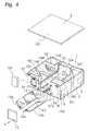
- FIGS. 1, 2, 3, and 4 show an oblique view, a top view, a side view, and an exploded oblique view, respectively, of the internal structure of a total heat exchanging unit according to one embodiment of the present invention.
- a total heat exchanging unit 100 is an apparatus for ventilating an indoor space while exchanging heat between supply air SA (solid line outline arrow) from an outdoor space and exhaust air EA (hatched outline arrow) from the indoor space via a heat exchange element 12.
- SA solid line outline arrow
- EA hatchched outline arrow
- the present total heat exchanging unit 100 principally comprises a casing 1, a heat exchange element 12, air filters 12b, ultraviolet light lamps 15, fans 10, 11, a damper 34, and an electrical equipment box EB.
- the casing 1 comprises a casing body 2 and a cover body 3, which covers the upper surface of the casing body 2. Furthermore, a heat exchange element chamber 21, an exhaust air fan motor housing chamber 41, an exhaust air fan housing chamber 22, a supply air fan motor housing chamber 43, a supply air fan housing chamber 24, a supply air communicating chamber 45, an exhaust air communicating chamber 46, an outdoor side suction chamber 26, an indoor side suction chamber 27, and a bypass chamber 31 are provided in the casing 1.
- a heat exchange element chamber 21 an exhaust air fan motor housing chamber 41, an exhaust air fan housing chamber 22, a supply air fan motor housing chamber 43, a supply air fan housing chamber 24, a supply air communicating chamber 45, an exhaust air communicating chamber 46, an outdoor side suction chamber 26, an indoor side suction chamber 27, and a bypass chamber 31 are provided in the casing 1.
- a heat exchange element chamber 21 an exhaust air fan motor housing chamber 41, an exhaust air fan housing chamber 22, a supply air fan motor housing chamber 43, a supply air fan housing chamber 24, a supply air communicating chamber 45, an exhaust air communicating chamber
- the heat exchange element chamber 21 is a rectangular parallelepipedic space, as shown in FIG. 1 and FIG. 3, and houses the heat exchange element 12. Furthermore, the heat exchange element chamber 21 is formed so that it is partitioned by, for example, a bottom plate of the casing body 2, partition plates 16A-16E (refer to FIG. 1, 5, and 6), and the cover body 3.
- guide parts G1, G2, G3 are affixed to the bottom plate of the casing body 2, the partition plates 16A-16E, and the cover body 3, respectively.
- the guide part G1, which is affixed to the bottom plate of the casing body 2 comprises a first guide part G11 and second guide parts G12.
- the first guide part G11 guides the ridgeline of the lower part of the heat exchange element 12 when the heat exchange element 12 is inserted or removed.
- a pair of second guide parts G12 is disposed so that the first guide part G11 is interposed therebetween, and guides the end edges of the pair of air filters 12b.
- the guide part G2, which is affixed to the partition plates 16A-16E, comprises a first guide part G21 and a second guide part G22.
- the first guide part G21 guides a ridgeline of a side part of the heat exchange element 12 when the heat exchange element 12 is inserted or removed.
- the second guide part G22 guides the end edges of the air filters 12b.
- the guide part G3, which is affixed to the cover body 3, guides a ridgeline of an upper part of the heat exchange element 12 when the heat exchange element 12 is inserted or removed.
- housing the heat exchange element 12 in the heat exchange element chamber 21 creates four substantially triangular prism shaped spaces 17, 18, 19, 20 therein.
- the spaces indicated by reference symbols 17, 18, 19, and 20 in FIG. 1 and FIG. 3 are called a first space, a second space, a third space, and a fourth space, respectively.
- the exhaust air fan housing chamber 22 houses the exhaust air fan 10, as shown in FIG. 1 and FIG. 4.
- the exhaust air fan housing chamber 22 communicates with the exhaust air fan motor housing chamber 41 via an opening 42, which is formed in the partition plate 16B.
- the exhaust air fan housing chamber 22 comprises an exhaust air outdoor side blow out port 7 on its side wall.
- the exhaust air fan motor housing chamber 41 houses an exhaust air fan motor 10M, as shown in FIG. 1 and FIG 4.
- the exhaust air fan motor housing chamber 41 communicates with the first space 17 via an opening 23, which is partitioned by the cover body 3 and one of the ridgelines of the heat exchange element 12, as shown in FIG. 1.
- the supply air fan housing chamber 24 houses the supply air fan 11, as shown in FIG. 1 and FIG. 4.
- the supply air fan housing chamber 24 communicates with the supply air fan motor housing chamber 43 via an opening 44, which is formed in the partition plate 16D, as shown in FIG. 1.
- the supply air fan housing chamber 24 comprises a supply air indoor side blow out port 6 on its side wall, as shown in FIG. 1.
- the supply air fan motor housing chamber 43 houses a supply air fan motor 11 M, as shown in FIG. 1 and FIG. 4. In addition, the supply air fan motor housing chamber 43 communicates with the second space 18 via an opening 25, which is partitioned by the cover body 3 and one of the ridgelines of the heat exchange element 12.
- the outdoor side suction chamber 26 comprises a supply air outdoor side suction port 5 on its side wall, as shown in FIG. 1.
- the outdoor side suction chamber 26 communicates with the supply air communicating chamber 45 via an opening 29 of the partition plate 16C, as shown in FIG. 1 and FIG. 5.
- the indoor side suction chamber 27 comprises an exhaust air indoor side suction port 4 on its side wall, as shown in FIG. 1.
- the indoor side suction chamber 27 communicates with the exhaust air communicating chamber 46 via an opening 30 of the partition plate 16E, as shown in FIG. 1.
- the supply air communicating chamber 45 is partitioned by the partition plate 16F, and is positioned below the exhaust air fan motor housing chamber 41. In addition, the supply air communicating chamber 45 communicates with the third space 19, as shown in FIG. 1.
- the exhaust air communicating chamber 46 is partitioned by the partition plate 16G, and is positioned below the supply air fan motor housing chamber 43. In addition, the exhaust air communicating chamber 46 communicates with the fourth space 20, as shown in FIG. 1.
- the bypass chamber 31 is positioned on the side opposite an extraction direction k of the heat exchange element chamber 21. Furthermore, the bypass chamber 31 communicates with the first space 17 via an opening 32. In addition, the bypass chamber 31 communicates with the indoor side suction chamber 27 via an opening 33. As a result, the exhaust air fan housing chamber 22 and the indoor side suction chamber 27 communicate via the exhaust air fan motor housing chamber 41, the first space 17, and the bypass chamber 31.
- the heat exchange element 12 is formed substantially as a rectangular parallelepiped, as shown in FIG. 1 and FIG. 4, and is provided to the intersecting portion between an exhaust air passageway 8 and a supply air passageway 9.
- the heat exchange element 12 has a laminar structure, wherein special pleated kraft paper (hereinbelow, referred to as spacer paper) 122 and special flat sheet shaped kraft paper (hereinbelow, referred to as partitioning paper) 121 are stacked in alternating directions, as shown in FIG. 7. Because the heat exchange element 12 is so structured, passageways in the heat exchange element 12 for the exhaust air EA and the supply air SA are disposed so that they alternate by level. Furthermore, with the heat exchange element 12, the sensible heat and the latent heat of the supply air SA and the exhaust air EA are exchanged via the partitioning paper 121.
- a handle 12a for removing the heat exchange element 12 is provided to an end surface of the heat exchange element 12, which can be inserted or removed in the longitudinal direction along its long side via an insertion/removal opening 13, which is open to a maintenance surface M of the casing 1, by removing a cover 14 as shown in FIG. 4.
- the air filters 12b are affixed to the heat exchange element 12 so that they cover the surfaces of the heat exchange element 12 that contact the third space 19 and the fourth space 20.
- Each of the air filters 12b is a nonwoven fabric that is made of polypropylene fibers.
- Each polypropylene fiber comprises a core part and an enveloping layer, and titanium apatite is supported on the enveloping layer.
- titanium apatite is an apatite wherein some of the calcium atoms of a calcium hydroxyapatite are substituted with titanium atoms using a technique such as ion exchange; titanium apatite exhibits excellent adsorption performance with respect to organic substances (particularly bacteria, viruses, and the like) and also exhibits properties of a photosemiconductor catalyst; in addition, if irradiated with light of a wavelength that has a high energy level (e.g., ultraviolet light and the like), then titanium apatite exhibits contaminant decomposition processing performance as a photosemiconductor catalyst superior to that of typical titanium dioxide of the anatase form.
- a technique such as ion exchange
- the ultraviolet light lamps 15 are provided to the third space 19 and the fourth space 20, respectively, and the supply of ultraviolet light thereby activates the photocatalytic function of the titanium apatite supported on the air filters 12b.
- the exhaust air fan 10 and the supply air fan 11 are sirocco fans (rotors), as shown in FIG. 2 and FIG. 3, and are housed inside a curled fan casing (not shown) that is made of a resin foam (e.g., expanded polystyrene). Furthermore, a rotational axis line L of each of the fans 10, 11 is parallel to the extraction direction K of the heat exchange element 12.
- the damper 34 is disposed inside the indoor side suction chamber 27.
- the damper 34 is pivoted by, for example, an electric motor (not shown) that opens either the opening 30 or the opening 33 and blocks the other.
- the electrical equipment box EB is disposed in a portion M1, which opposes the exhaust air fan 10, of the maintenance surface M.
- the electrical equipment box EB houses electrical equipment, such as a control circuit board (not shown). Furthermore, the control circuit board is connected to and in communication with a wired remote control (not shown), and controls the operation of the fans 10, 11 and the damper 34 based on signals sent from the wired remote control.
- Table 1 shows the percentage of viruses, bacteria, and toxins inactivated by titanium apatite. TABLE 1 Target Sample Inactivity Percentage Testing Institution Certification Number Influenza virus ⁇ 99.99% Japan Food Research Laboratories No. 203052102 Antimicrobial Escherichia coli (O157) ⁇ 99.99% Japan Food Research Laboratories No. 203030567-001 Staphylococcus aureus ⁇ 99.99% Japan Food Research Laboratories No. 203030567-001 Cladosporium ⁇ 99.99% Japan Food Research Laboratories No. 203030567-001 Toxin Enterotoxin ⁇ 99.9% Japan Food Research Laboratories No. 203050715-001
- influenza virus suspension was dropped onto titanium apatite-coated filters (approximately 30 x 30 mm) and preserved at room temperature under dark (shielded from light) and light (black light irradiation with a distance of approximately 20 cm between the filter and the black light) conditions; after 24 hours, the virus infectivity titer was measured.
- Inactivity percentage 100 ⁇ 1 - 10 B / 10 A
- Test virus Influenza virus type A (H1N1)
- MDCK NBL-2 cells
- ATCC CCL-34 Dainippon Pharmaceutical Co., Ltd.
- tissue culture was used: Eagle MEM 1,000 mL NaHCO 3 (10%) 24-44 mL L-glutamine (30 g/L) 9.8 mL Vitamin solution for 100 ⁇ MEM 30 mL Albumin (10%) 20 mL Trypsin (5 mg/mL) 2 mL
- the filter (approximately 30 x 30 mm) was sterilized with moist heat (121° C for 15 min), it was air dried for one hour, placed in a plastic Petri dish, irradiated with black light (black light blue, two FL20S BL-B 20W bulbs in parallel) for over 12 hours, and then used as a sample.
- moist heat 121° C for 15 min
- 0.2 mL of the virus suspension was dropped onto the sample.
- the samples were maintained at room temperature under light shielded and black light irradiation (distance of approximately 20 cm between the filter and the black light) conditions.
- black light irradiation distance of approximately 20 cm between the filter and the black light
- polyethylene film was used as the control sample, and tested in the same manner.
- the cell growth medium was used to incubate a monolayer culture of MDCK cells in a tissue culture microplate (96 wells), after which the cell growth medium was eliminated and the cell maintenance medium was added 0.1 mL at a time. Next, a washout liquid and 0.1 mL of a diluted solution thereof were used to seed 4 wells each, which were then incubated for 4 to 7 days at 37° C in a CO 2 incubator (5% CO 2 concentration).
- TCID 50 50% tissue culture infectious dose
- Bacterial suspensions of Escherichia coli, staphylococcus aureus, and Cladosporium were dropped onto samples, which were then sealed by covering them with a low density polyethylene film. These samples were preserved at room temperature (20°-25° C) under dark (shielded from light) and light (black light irradiation with a distance of approximately 20 cm between the filters and the black light) conditions; after 24 hours, the viable cell count was measured.
- Test strains were incubated beforehand in the NA medium at 35° C for 16 to 24 hours, the NA medium was reseeded with that culture, and the bacteria bodies, which were incubated at 35° C for 16 to 20 hours, were evenly dispersed in the 1/500 NB medium, and then prepared so that the bacteria count per milliliter was 2.5 ⁇ 10 5 to 1.0 ⁇ 10 6 .
- the spores (conidias) were suspended in a 0.005% dioctyl sodium sulfosuccinate solution, filtered with gauze, and then prepared so that the spore count per milliliter was 2.5 ⁇ 10 5 to 1.0 ⁇ 10 6 .
- each filter (approximately 50 ⁇ 50 mm) was sterilized with moist heat (121° C for 15 min), it was air dried for one hour, placed in a plastic Petri dish, irradiated for over 12 hours with black light (black light blue, two FL20S BL-B 20W bulbs in parallel), and then used as a sample.
- each bacterial suspension was dropped onto a sample, which was then sealed by covering it with low density polyethylene film (40 ⁇ 40 mm).
- the samples were preserved at room temperature (20°-25° C) under light shielded and black light irradiation (with a distance of approximately 20 cm between the filter and the black light) conditions.
- the polyethylene film was used as the control sample and tested in the same manner.
- the surviving bacteria were washed out from each sample with the SCDLP medium and the viable cell count of the washout liquid was measured by the poured plate culture method, wherein the SA medium was used for the microbes (incubated for 2 days at 35° C) and the PDA medium was used for the fungi (incubated for 7 days at 25° C); thereafter, the viable cell count per sample was calculated. In addition, immediately after seeding, this measurement was performed on the control sample.
- the samples were seeded with staphylococcal enterotoxin A (hereinafter, abbreviated as "SET-A”) and then preserved at room temperature (20°-25° C) under dark (shielded from light) and light (irradiated with ultraviolet light with a luminous flux of approximately 1 mW/cm 2 ) conditions; 24 hours later, the concentration of the SET-A was measured and the decomposition percentage was calculated.
- SET-A staphylococcal enterotoxin A
- a 5 ⁇ g/mL standard stock solution was prepared by dissolving a SET-A reference sample (Toxin Technology Inc.) in a 1% sodium chloride solution containing 0.5% bovine serum albumin.
- Standard solutions of 0.2, 0.5, and 1 ng/mL were prepared by diluting the standard stock solution with the buffer solution included with the VIDAS staphylococcus enterotoxin (SET) test kit (bioMérieux, Inc.).
- SET staphylococcus enterotoxin
- the filter was cut into 50 ⁇ 50 mm pieces, irradiated for 24 hours with a black light from a distance of approximately 1 cm, and then used as the samples.
- Each sample was placed in a plastic Petri dish and seeded with 0.4 mL of SET-A standard stock solution.
- the samples were preserved at room temperature (20°-25° C) under light shielded and light irradiation (black light, two FL20S BL-B 20W bulbs in parallel), with an ultraviolet light luminous flux of approximately 1 mW/cm 2 conditions.
- the SET-A was washed out from each sample with 10 mL of a buffer solution, which was included in the VIDAS staphylococcus enterotoxin (SET) test kit (bioMérieux, Inc.).
- a plastic Petri dish wherein a sample was not placed, was seeded with 0.4 mL of SET-A standard stock solution, and then 10 mL of buffer solution, which was included in the VIDAS staphylococcus enterotoxin (SET) test kit (bioMérieux, Inc.), was immediately added, and the result was used as the control.
- SET staphylococcus enterotoxin
- the concentration and the fluorescent light intensity of the calibration curve standard solution were measured by the ELISA method using a VIDAS staphylococcus enterotoxin (SET) test kit (bioMérieux, Inc.), and the calibration curve was generated based on those measurements.
- SET VIDAS staphylococcus enterotoxin
- the total heat exchanging unit 100 is provided with three operation modes, i.e., a total heat exchange ventilation mode, a normal ventilation mode, and the air filter cleaning mode. The following describes the details of each of these operation modes.
- the damper 34 opens the opening 30. Furthermore, as discussed above, the opening 33 is blocked at this time. Furthermore, if the fans 10, 11 are operated in this state, the indoor air is suctioned via a duct from the indoor side suction port 4 into the indoor side suction chamber 27, passes through the exhaust air passageway 8, which extends from the opening 30 to the exhaust air communicating chamber 46, the fourth space 20, the air filters 12b, the heat exchange element 12, the first space 17, the opening 23, the exhaust air fan motor housing chamber 41, and the exhaust air fan housing chamber 22, and is then blown out from the outdoor side blow out port 7 and exhausted to the outdoor space via a duct; simultaneously, the outdoor air is suctioned via a duct from the outdoor side suction port 5 into the outdoor side suction chamber 26, passes through the supply air passageway 9, which extends from the supply air communicating chamber 45 to the third space 19, the air filters 12b, the heat exchange element 12, the second space 18, the opening 25, the supply air fan
- Normal ventilation which does not perform heat exchange, is performed during intermediate seasons, such as spring and fall, when cooling and heating are not needed.
- the damper 34 opens the opening 33. Furthermore, as discussed above, the opening 30 is blocked at this time. Furthermore, if the fans 10, 11 are operated in this state, the indoor air is suctioned via a duct from the indoor side suction port 4 into the indoor side suction chamber 27, passes through a bypass ventilation passageway, which extends from the opening 33 to the bypass chamber 31, the opening 32, the first space 17, the opening 23, exhaust air fan motor housing chamber 41, and the exhaust air fan housing chamber 22, and is then blown out from the outdoor side blow out port 7 and exhausted via a duct to the outdoor space; simultaneously, the outdoor air is suctioned via a duct from the outdoor side suction port 5 into the outdoor side suction chamber 26, passes through the supply air passageway 9, which extends from the supply air communicating chamber 45 to the third space 19, the air filters 12b, the heat exchange element 12, the second space 18, the opening 25, the supply air fan motor housing chamber 43, the opening 44, and the supply air fan housing chamber 24, and is then blown out from
- the heat exchange element 12 is a total heat exchanging type that comprises the moisture permeable spacer paper 122 and the partitioning paper 121. Furthermore, an air filter 12b is provided to the heat exchange element 12 not only on the supply airflow upstream side, but also on the exhaust airflow upstream side. In addition, both air filters 12b support titanium apatite. Furthermore, the catalytic function of the titanium apatite is activated by ultraviolet light lamps 15, which are provided nearby. Titanium apatite exhibits decomposition capacity with respect to, for example, bacteria, viruses and the like that is stronger than titanium dioxide of the anatase form. Consequently, the total heat exchanging unit 100 can prevent, more effectively than a conventional heat exchanging unit, contamination of the heat exchange element 12 due to, for example, dust, bacteria, viruses or the like suspended in the outdoor air.
- the ultraviolet light lamps 15 are provided to the total heat exchanging unit 100 in the vicinity of the air filters 12b. Consequently, the total heat exchanging unit 100 can also be disposed in outdoor and indoor where light does not reach.
- the catalytic function of the titanium apatite is activated by the ultraviolet light lamps 15. Accordingly, it is possible to hold down the manufacturing cost of the total heat exchanging unit 100.
- the heat exchange element 12 is a total heat exchanging type that comprises the moisture permeable spacer paper 122 and partitioning paper 121, but the heat exchange element 12 may also be a sensible heat exchange type (a so-called heat pipe type heat exchange element) that comprises a moisture impermeable spacer plate and partition plate. Furthermore, with the sensible heat exchange type heat exchange element, only sensible heat is exchanged between the supply air and the exhaust air. In this case, a constitution may be adopted wherein an air filter 12b is provided only on the supply airflow upstream side. This is because, with the sensible heat exchange type heat exchange element, the supply air and the exhaust air do not mix, and therefore there is no risk that the dust, bacteria, viruses or the like contained in the exhaust air will mix into the supply air.
- the heat exchange element is a fixed type, but may be a rotational type heat exchange element 220, as shown in FIG. 9.
- the rotational type heat exchange element 220 principally comprises a casing 221, a rotor 222, a gear motor 223, and a partition plate 224, as shown in FIG. 9.
- the casing 221 houses the rotor 222 and the gear motor 223.
- the rotor 222 is rotatably fixed to the casing 221.
- the gear motor 223 rotatably drives the rotor 222 via a belt.
- the rotor 222 has a honeycomb construction that comprises aluminum plates.
- a heat exchange element wherein the aluminum plates are coated with a moisture absorbent, for example, sodium chloride or a siliceous compound, is used as the total heat exchange heat exchange element, and one wherein the aluminum plates are not coated is used as the sensible heat exchange heat exchange element.
- the partition plate 224 partitions the rotor 222 in the vertical direction. In so doing, with the rotational type heat exchange element 220, the exhaust air passes through the upper half of the rotor 222, and the supply air passes through the lower half. In so doing, with the total heat exchanging type heat exchange element, the temperature and humidity of the exhaust air is higher than the outdoor air in, for example, the winter season, and the temperature and moisture content of the upper half of the rotor 222 itself rises due to the exhaust air. In this state, if the rotor 222 rotates and a portion that was in the area of the abovementioned upper half moves to the area of the lower half, then that portion contacts the supply air and throws off its temperature and humidity thereto.
- FIG. 8 shows a heat exchanging unit 200 wherein such rotational type heat exchange elements 220 are installed.
- the heat exchanging unit 200 principally comprises a casing 201, the heat exchange elements 220, air filters 220b, an ultraviolet light lamp (not shown), and fans 210, 211, as shown in FIG. 8.
- the heat exchange elements 220 are disposed in the vicinity of substantially the center of the casing 201 in the longitudinal direction so that the rotational axes of the rotors 222 coincide with the longitudinal direction.
- two rotors 222 are disposed lined up in a direction orthogonal to the longitudinal direction.
- the air filters 220b are disposed on the exhaust airflow upstream side and on the supply airflow upstream side of the rotor 222.
- the air filter 220b that is disposed on the exhaust airflow upstream side of the rotors 222 covers the upper half of the rotors 222.
- the air filter 220b that is disposed on the supply airflow upstream side of the rotors 222 covers the lower half of the rotors 222.
- the air filters 220b are the same as the air filters 12b according to the previous embodiment.
- titanium apatite is disposed in the vicinity of the air filters 220b, and the ultraviolet light lamp (not shown) activates its catalytic function.
- the exhaust air fan 210 is provided on the outdoor side of the heat exchanging unit 200 and is driven by an exhaust air fan motor 210M.
- the supply air fan 211 is provided on the indoor side of the heat exchanging unit 200 and is driven by a supply air fan motor 211 M.
- the indoor air is sucked into an indoor side suction port 254 via a duct, passes through an exhaust air passageway that extends from the air filters 220b to the heat exchange element 220 and the exhaust air fan 210, is then blown out from an outdoor side blow out port 257 and exhausted to the outdoor space via a duct; simultaneously, outdoor air is sucked into an outdoor side suction port 255 via a duct, passes through a supply air passageway that extends from the air filters 220b to the heat exchange element 220 and the supply air fan 211, and is then blown out from an indoor side blow out port 256 and supplied to the indoor space via a duct.
- the total heat exchanging unit 100 employs the ultraviolet light lamps 15 in order to activate the catalytic function of the titanium apatite, but an LED may be used instead. Doing so can contribute to energy conservation and a reduction in the global environmental load (because mercury is not used in the LED), and can also hold down manufacturing costs.
- the total heat exchanging unit 100 uses the ultraviolet light lamps 15 in order to activate the catalytic function of the titanium apatite; however, if the total heat exchanging unit 100 is installed in outdoor or indoor where light reaches, then at least one of the casing 1 and the cover body 3 may be made transparent, and the titanium apatite may be activated by at least one of outdoor light and indoor light.
- the total heat exchanging unit 100 uses the ultraviolet light lamps 15 in order to activate the catalytic function of the titanium apatite, but a streamer discharger, a glow discharger, a barrier discharger, or the like may be used instead.
- a discharger By disposing such a discharger in the total heat exchanging unit 100, it is possible to supply, for example, ozone and high energy radicals that have a bactericidal effect on the titanium apatite.
- the total heat exchanging unit 100 increases the bactericidal effect and can also accelerate the photocatalytic reaction speed of the titanium apatite.
- the heat exchanging unit 100 can prevent, more effectively than a conventional heat exchanging unit, the contamination of the heat exchange element 12 due to, for example, dust, bacteria, or viruses that are suspended in the outdoor air.
- an air filter cleaning mode may be made available in addition to the total heat exchange ventilation mode and the normal ventilation mode.
- the air filter cleaning mode the rotational speed of the fans 10, 11 is controlled so that it transitions to a state wherein the amount of ventilation is suppressed as much as possible.
- the plasma discharger may be constituted so that it is energized only in this mode, or so that it is continuously energized. In so doing, a high concentration of radicals is supplied to the air filters 12b. Accordingly, with the total heat exchanging unit 100, it is possible to selectively and efficiently purify the air filters 12b.
- titanium apatite is supported in a form wherein it is embedded in the enveloping layer of the polypropylene fibers, but it may be coated thereon.
- polypropylene fibers are used as the support body of the titanium apatite, but the support body of the titanium apatite is not limited thereto.
- the support body of the titanium apatite is not limited thereto.
- titanium apatite is supported in a form wherein it is embedded in the enveloping layer of the polypropylene fibers, but it may be coated on one or both sides of each air filter 12b.
- a heat exchanging unit according to the present invention can prevent, more effectively than a conventional heat exchanging unit, the contamination of a heat exchange element due to, for example, dust, bacteria, viruses or the like suspended in the outdoor air, and can also be adapted to applications such as an air conditioner or an air cleaner.
Landscapes
- Engineering & Computer Science (AREA)
- Chemical & Material Sciences (AREA)
- Combustion & Propulsion (AREA)
- Mechanical Engineering (AREA)
- General Engineering & Computer Science (AREA)
- Chemical Kinetics & Catalysis (AREA)
- Health & Medical Sciences (AREA)
- Environmental & Geological Engineering (AREA)
- General Chemical & Material Sciences (AREA)
- Analytical Chemistry (AREA)
- Biomedical Technology (AREA)
- Oil, Petroleum & Natural Gas (AREA)
- Epidemiology (AREA)
- Life Sciences & Earth Sciences (AREA)
- Animal Behavior & Ethology (AREA)
- General Health & Medical Sciences (AREA)
- Public Health (AREA)
- Veterinary Medicine (AREA)
- Disinfection, Sterilisation Or Deodorisation Of Air (AREA)
- Central Air Conditioning (AREA)
- Exhaust Gas Treatment By Means Of Catalyst (AREA)
- Catalysts (AREA)
Abstract
It is an object of the present invention to provide a heat exchanging unit (100, 200) that can maintain, more effectively than a conventional heat exchanging unit, the cleanliness of a heat exchange element (12, 220). The heat exchanging unit (100, 200) comprises an indoor air exhaust passageway (8), an outdoor air supply passageway (9), a heat exchange element (12, 220), and a first air cleaning member (12b, 220b). The indoor air exhaust passageway (8) exhausts indoor air to an outdoor space as exhaust air (EA). The outdoor air supply passageway (9) supplies outdoor air to an indoor space as supply air (SA). The heat exchange element (12, 220) exchanges at least the sensible heat of the sensible heat and the latent heat between the exhaust air (EA) and the supply air (SA). In addition, the heat exchange element (12, 220) communicates with the indoor air exhaust passageway (8) and the outdoor air supply passageway (9). The first air cleaning member (12b, 220b) is provided to the supply airflow upstream side of the heat exchange element (12, 220). In addition, the first air cleaning member (12b, 220b) supports an apatite that has a photocatalytic function.
Description
- The present invention relates to a heat exchanging unit that efficiently recovers heat during ventilation.
- There is a technology (e.g., refer to Patent Document 1) that aims to prevent contamination of a heat exchange element of a total heat exchanging unit (due to, for example, dust, bacteria, viruses or the like suspended in the outdoor air) by disposing an air filter, whereon a photocatalyst is supported, on the supply airflow upstream side of the heat exchange element.
-
Japanese Published Unexamined Patent Application No. H 10-311581 - It is an object of the present invention to provide a heat exchanging unit that can prevent, more effectively than the conventional case, the contamination of a heat exchange element due to, for example, dust, bacteria, viruses or the like suspended in the outdoor air.
- A heat exchanging unit according to a first aspect of the present invention comprises an indoor air exhaust passageway, an outdoor air supply passageway, a heat exchange element and a first air cleaning member. Furthermore, the "heat exchanging unit" herein includes both a total heat exchanging unit and a sensible heat exchanging unit. The indoor air exhaust passageway exhausts indoor air to an outdoor space as exhaust air. The outdoor air supply passageway supplies outdoor air to an indoor space as supply air. The heat exchange element exchanges at least the sensible heat of the sensible heat and the latent heat between the exhaust air and the supply air. Furthermore, the heat exchange element may be a fixed type or a rotational type. In addition, "sensible heat" herein specifically means temperature. In addition, "latent heat" herein specifically means humidity. In addition, the heat exchange element communicates with the indoor air exhaust passageway and the outdoor air supply passageway. The first air cleaning member is provided on the supply airflow upstream side of the heat exchange element. In addition, the first air cleaning member supports apatite that has a photocatalytic function. Furthermore, the "air cleaning member" herein is, for example, an air filter, an electric precipitator or the like. In addition, the "apatite that has a photocatalytic function" herein is an apatite wherein, for example, some of the calcium atoms of calcium hydroxyapatite are substituted by titanium atoms by a technique such as ion exchange or the like. In addition, the apatite that has a photocatalytic function may be supported on an air cleaning member by mixing it into, for example, a resin, or may be supported on the air cleaning member by coating it thereon. In addition, the apatite that has a photocatalytic function may be activated by a light source, such as an ultraviolet light lamp or an LED, by outdoor or indoor light, or by a plasma discharger and the like.
- Herein, the first air cleaning member is provided on the supply airflow upstream side of the heat exchange element. In addition, the first air cleaning member supports the apatite that has a photocatalytic function. The apatite that has a photocatalytic function exhibits a decomposition capacity that is greater than titanium dioxide with respect to, for example, bacteria, viruses and the like. Consequently, if the photocatalytic function of the apatite that has a photocatalytic function can be activated, then this heat exchanging unit can prevent, more effectively than a conventional heat exchanging unit, the contamination of the heat exchange element due to, for example, dust, bacteria, viruses or the like suspended in the outdoor air.
- A heat exchanging unit according to a second aspect of the present invention is a heat exchanging unit according to a first aspect of the present invention, further comprising a second air cleaning member. The second air cleaning member is provided on the exhaust airflow upstream side of the heat exchange element. In addition, the second air cleaning member supports the apatite that has a photocatalytic function.
- If the heat exchange element is a rotational type or a moisture permeable fixed type (i.e., a total heat exchanging type), then some of the exhaust air or the return air will mix with the supply air, and the bacteria, viruses and the like present in the exhaust air or the return air will unfortunately return back with the supply air.
- However, the second air cleaning member herein is provided on the exhaust airflow upstream side of the heat exchange element. In addition, the second air cleaning member supports the apatite that has a photocatalytic function. Consequently, with this heat exchanging unit, if the photocatalytic function of the apatite that has a photocatalytic function can be activated, then the bacteria, viruses and the like present in the exhaust air or the return air will be decomposed, destroyed or deactivated by the time they arrive at the heat exchange element. Accordingly, this heat exchanging unit can prevent the return of bacteria, viruses, and the like present in the exhaust air or the return air back with the supply air, regardless of whether the heat exchange element is a rotational type or a moisture permeable fixed type. In addition, the heat exchanging unit can also effectively prevent the contamination of the heat exchange element due to, for example, dust, bacteria or viruses suspended in the indoor air.
- A heat exchanging unit according to a third aspect of the present invention is a heat exchanging unit according to a first aspect or a second aspect of the present invention, further comprising a photocatalytic function activating part. The photocatalytic function activating part activates the photocatalytic function of the apatite. Furthermore, the "photocatalytic function activating part" herein is, for example, an ultraviolet light lamp, an LED, a plasma discharger (such as a glow discharger, a barrier discharger, or a streamer discharger) or the like.
- Here, the photocatalytic function activating part activates the photocatalytic function of the apatite. Consequently, the heat exchanging unit can also be disposed in outdoor and indoor where light does not reach.
- A heat exchanging unit according to a fourth aspect of the present invention is a heat exchanging unit according to a third aspect of the present invention, wherein the photocatalytic function activating part irradiates the apatite that has a photocatalytic function with light in a predetermined wavelength range. Furthermore, the "photocatalytic function activating part" herein is, for example, an ultraviolet light lamp, a purple LED or the like.
- Here, the photocatalytic function activating part irradiates the apatite that has a photocatalytic function with light in a predetermined wavelength range. Consequently, it is possible to use, for example, an ultraviolet light lamp or an LED in order to activate the photocatalytic function of the apatite that has a photocatalytic function. Accordingly, the manufacturing cost of the heat exchanging unit can be held down.
- A heat exchanging unit according to a fifth aspect of the present invention is a heat exchanging unit according to a third aspect of the present invention, wherein the photocatalytic function activating part is provided on the airflow upstream side of the air cleaning member. In addition, the photocatalytic function activating part supplies activators to the apatite that has a photocatalytic function. Furthermore, the "photocatalytic function activating part" herein is, for example, a glow discharger, a barrier discharger, a streamer discharger or the like. The "activators" herein are, for example, high speed electrons, ions, ozone, radicals such as hydroxy radicals, other excited molecules (such as excited oxygen molecules, excited nitrogen molecules, and excited water molecules) and the like.
- Here, the photocatalytic function activating part is provided on the airflow upstream side of the air cleaning member. Furthermore, the photocatalytic function activating part supplies activators to the apatite that has a photocatalytic function. Consequently, with this heat exchanging unit, the high energy radicals can activate the photocatalytic function of the apatite that has a photocatalytic function. Accordingly, it is possible to accelerate the photocatalytic reaction speed of the apatite that has a photocatalytic function. As a result, the heat exchanging unit can prevent, more effectively than a conventional heat exchanging unit, the contamination of the heat exchange element due to, for example, dust, bacteria, viruses or the like suspended in the outdoor air. In addition, it is known that ozone is extremely effective against a bactericide and the like. Consequently, the heat exchanging unit can prevent, more effectively than a conventional heat exchanging unit, the contamination of the heat exchange element due to, for example, dust, bacteria, viruses or the like suspended in the outdoor air.
- A heat exchanging unit according to a sixth aspect of the present invention is a heat exchanging unit according to a fifth aspect of the present invention, further comprising an air distribution part and an operation switching unit. Furthermore, the "air distribution part" herein is, for example, a fan. The air distribution part distributes the air. The operation switching unit switches the operation state of the air distribution part. Furthermore, the "operation switching unit" herein is, for example, a control device that switches the rotational speed of the impeller of a fan.
- Here, the operation switching unit switches the operation state of the air distribution part. Consequently, a high concentration of activators is supplied to the air cleaning member if the photocatalytic function activating part is used in a state wherein, for example, during normal operation, dust, bacteria, viruses and the like are captured in advance by the air cleaning member without making use of the photocatalytic function activating part, operation is then switched to a cleaning operation mode after a fixed time, and the air volume of the fan is maximally suppressed. Accordingly, with this heat exchanging unit, the air cleaning member can be cleaned selectively and effectively.
- If the photocatalytic function of the apatite that has a photocatalytic function can be activated, then the heat exchanging unit of the first aspect of the invention can prevent, more effectively than a conventional heat exchanging unit, the contamination of the heat exchange element due to, for example, dust, bacteria, viruses or the like suspended in the outdoor air.
- With the heat exchanging unit of the second aspect of the invention, if the photocatalytic function of the apatite that has a photocatalytic function can be activated, then the bacteria, viruses and the like present in the exhaust air or the return air will be decomposed, destroyed or deactivated by the time they arrive at the heat exchange element. Accordingly, this heat exchanging unit can prevent the return of bacteria, viruses, and the like present in the exhaust air or the return air back with the supply air, regardless of whether the heat exchange element is a rotational type or a moisture permeable fixed type. In addition, the heat exchanging unit can also effectively prevent the contamination of the heat exchange element due to, for example, dust, bacteria, viruses or the like suspended in the indoor air.
- The heat exchanging unit of the third aspect of the invention can also be disposed in outdoor and indoor where light does not reach.
- The manufacturing cost of the heat exchanging unit according to the fourth aspect of the invention can be held down.
- The heat exchanging unit according to the fifth aspect of the invention can prevent, more effectively than a conventional heat exchanging unit, the contamination of the heat exchange element due to, for example, dust, bacteria, viruses or the like suspended in the outdoor air. In addition, it is known that ozone is extremely effective against a bactericide and the like. Consequently, the heat exchanging unit can prevent, more effectively than a conventional heat exchanging unit, the contamination of the heat exchange element due to, for example, dust, bacteria, viruses or the like suspended in the outdoor air.
- With the heat exchanging unit according to the sixth aspect of the invention, the air cleaning member can be cleaned selectively and effectively.
-
- FIG. 1 is an oblique view that shows the internal structure of a total heat exchanging unit according to the present invention.
- FIG 2 is a top view that shows the internal structure of a total heat exchanging unit according to the present invention.
- FIG. 3 is a side view that shows the internal structure of a total heat exchanging unit according to the present invention.
- FIG. 4 is an exploded oblique view that shows the internal structure of the total heat exchanging unit according to the present invention.
- FIG. 5 is an oblique view of a partition plate.
- FIG. 6 is an oblique view of a partition plate.
- FIG. 7 is an oblique view that shows the structure of a heat exchange element.
- FIG. 8 is an oblique view that shows the internal structure of the heat exchanging unit according to a modified example (B).
- FIG. 9 is an oblique view that shows the structure of the heat exchange element according to a modified example (B).
-
- 8
- Exhaust air passageway (indoor air exhaust passageway)
- 9
- Supply air passageway (outdoor air supply passageway)
- 10,11,210,211
- Fans (air distribution part)
- 12, 220
- Heat exchange elements
- 12b, 220b
- Air filters (first air cleaning member, second air cleaning member)
- 15
- Ultraviolet light lamp (photocatalytic function activating part)
- 100, 200
- Total heat exchanging units (heat exchanging units)
- EB
- Electrical equipment box (operation switching unit)
- EA
- Exhaust air
- SA
- Supply air
- FIGS. 1, 2, 3, and 4 show an oblique view, a top view, a side view, and an exploded oblique view, respectively, of the internal structure of a total heat exchanging unit according to one embodiment of the present invention. Furthermore, as shown in FIG. 1, a total
heat exchanging unit 100 is an apparatus for ventilating an indoor space while exchanging heat between supply air SA (solid line outline arrow) from an outdoor space and exhaust air EA (hatched outline arrow) from the indoor space via aheat exchange element 12. - As shown in FIGS. 1, 2, 3, and 4, the present total
heat exchanging unit 100 principally comprises acasing 1, aheat exchange element 12,air filters 12b,ultraviolet light lamps 15,fans damper 34, and an electrical equipment box EB. - As shown in FIG. 1 and FIG. 4, the
casing 1 comprises acasing body 2 and acover body 3, which covers the upper surface of thecasing body 2. Furthermore, a heatexchange element chamber 21, an exhaust air fanmotor housing chamber 41, an exhaust airfan housing chamber 22, a supply air fanmotor housing chamber 43, a supply airfan housing chamber 24, a supplyair communicating chamber 45, an exhaustair communicating chamber 46, an outdoorside suction chamber 26, an indoorside suction chamber 27, and abypass chamber 31 are provided in thecasing 1. The following describes the details of each of the chambers discussed above. - The heat
exchange element chamber 21 is a rectangular parallelepipedic space, as shown in FIG. 1 and FIG. 3, and houses theheat exchange element 12. Furthermore, the heatexchange element chamber 21 is formed so that it is partitioned by, for example, a bottom plate of thecasing body 2,partition plates 16A-16E (refer to FIG. 1, 5, and 6), and thecover body 3. In addition, guide parts G1, G2, G3 are affixed to the bottom plate of thecasing body 2, thepartition plates 16A-16E, and thecover body 3, respectively. The guide part G1, which is affixed to the bottom plate of thecasing body 2, comprises a first guide part G11 and second guide parts G12. The first guide part G11 guides the ridgeline of the lower part of theheat exchange element 12 when theheat exchange element 12 is inserted or removed. Moreover, a pair of second guide parts G12 is disposed so that the first guide part G11 is interposed therebetween, and guides the end edges of the pair ofair filters 12b. The guide part G2, which is affixed to thepartition plates 16A-16E, comprises a first guide part G21 and a second guide part G22. The first guide part G21 guides a ridgeline of a side part of theheat exchange element 12 when theheat exchange element 12 is inserted or removed. Moreover, the second guide part G22 guides the end edges of theair filters 12b. The guide part G3, which is affixed to thecover body 3, guides a ridgeline of an upper part of theheat exchange element 12 when theheat exchange element 12 is inserted or removed. - Furthermore, housing the
heat exchange element 12 in the heatexchange element chamber 21 creates four substantially triangular prism shapedspaces reference symbols - The exhaust air
fan housing chamber 22 houses theexhaust air fan 10, as shown in FIG. 1 and FIG. 4. In addition, as shown in FIG. 1, the exhaust airfan housing chamber 22 communicates with the exhaust air fanmotor housing chamber 41 via anopening 42, which is formed in thepartition plate 16B. In addition, as shown in FIG. 1, the exhaust airfan housing chamber 22 comprises an exhaust air outdoor side blow out port 7 on its side wall. - The exhaust air fan
motor housing chamber 41 houses an exhaustair fan motor 10M, as shown in FIG. 1 and FIG 4. In addition, the exhaust air fanmotor housing chamber 41 communicates with thefirst space 17 via anopening 23, which is partitioned by thecover body 3 and one of the ridgelines of theheat exchange element 12, as shown in FIG. 1. - The supply air
fan housing chamber 24 houses thesupply air fan 11, as shown in FIG. 1 and FIG. 4. In addition, the supply airfan housing chamber 24 communicates with the supply air fanmotor housing chamber 43 via anopening 44, which is formed in thepartition plate 16D, as shown in FIG. 1. In addition, the supply airfan housing chamber 24 comprises a supply air indoor side blow outport 6 on its side wall, as shown in FIG. 1. - The supply air fan
motor housing chamber 43 houses a supplyair fan motor 11 M, as shown in FIG. 1 and FIG. 4. In addition, the supply air fanmotor housing chamber 43 communicates with thesecond space 18 via anopening 25, which is partitioned by thecover body 3 and one of the ridgelines of theheat exchange element 12. - The outdoor
side suction chamber 26 comprises a supply air outdoorside suction port 5 on its side wall, as shown in FIG. 1. In addition, the outdoorside suction chamber 26 communicates with the supplyair communicating chamber 45 via anopening 29 of thepartition plate 16C, as shown in FIG. 1 and FIG. 5. - The indoor
side suction chamber 27 comprises an exhaust air indoorside suction port 4 on its side wall, as shown in FIG. 1. In addition, the indoorside suction chamber 27 communicates with the exhaustair communicating chamber 46 via anopening 30 of thepartition plate 16E, as shown in FIG. 1. - The supply
air communicating chamber 45 is partitioned by thepartition plate 16F, and is positioned below the exhaust air fanmotor housing chamber 41. In addition, the supplyair communicating chamber 45 communicates with thethird space 19, as shown in FIG. 1. - The exhaust
air communicating chamber 46 is partitioned by thepartition plate 16G, and is positioned below the supply air fanmotor housing chamber 43. In addition, the exhaustair communicating chamber 46 communicates with thefourth space 20, as shown in FIG. 1. - The
bypass chamber 31 is positioned on the side opposite an extraction direction k of the heatexchange element chamber 21. Furthermore, thebypass chamber 31 communicates with thefirst space 17 via anopening 32. In addition, thebypass chamber 31 communicates with the indoorside suction chamber 27 via anopening 33. As a result, the exhaust airfan housing chamber 22 and the indoorside suction chamber 27 communicate via the exhaust air fanmotor housing chamber 41, thefirst space 17, and thebypass chamber 31. - The
heat exchange element 12 is formed substantially as a rectangular parallelepiped, as shown in FIG. 1 and FIG. 4, and is provided to the intersecting portion between anexhaust air passageway 8 and asupply air passageway 9. Theheat exchange element 12 has a laminar structure, wherein special pleated kraft paper (hereinbelow, referred to as spacer paper) 122 and special flat sheet shaped kraft paper (hereinbelow, referred to as partitioning paper) 121 are stacked in alternating directions, as shown in FIG. 7. Because theheat exchange element 12 is so structured, passageways in theheat exchange element 12 for the exhaust air EA and the supply air SA are disposed so that they alternate by level. Furthermore, with theheat exchange element 12, the sensible heat and the latent heat of the supply air SA and the exhaust air EA are exchanged via thepartitioning paper 121. - Furthermore, a
handle 12a for removing theheat exchange element 12 is provided to an end surface of theheat exchange element 12, which can be inserted or removed in the longitudinal direction along its long side via an insertion/removal opening 13, which is open to a maintenance surface M of thecasing 1, by removing acover 14 as shown in FIG. 4. - As shown in FIG. 4, the
air filters 12b are affixed to theheat exchange element 12 so that they cover the surfaces of theheat exchange element 12 that contact thethird space 19 and thefourth space 20. Each of theair filters 12b is a nonwoven fabric that is made of polypropylene fibers. Each polypropylene fiber comprises a core part and an enveloping layer, and titanium apatite is supported on the enveloping layer. Furthermore, titanium apatite is an apatite wherein some of the calcium atoms of a calcium hydroxyapatite are substituted with titanium atoms using a technique such as ion exchange; titanium apatite exhibits excellent adsorption performance with respect to organic substances (particularly bacteria, viruses, and the like) and also exhibits properties of a photosemiconductor catalyst; in addition, if irradiated with light of a wavelength that has a high energy level (e.g., ultraviolet light and the like), then titanium apatite exhibits contaminant decomposition processing performance as a photosemiconductor catalyst superior to that of typical titanium dioxide of the anatase form. - The
ultraviolet light lamps 15 are provided to thethird space 19 and thefourth space 20, respectively, and the supply of ultraviolet light thereby activates the photocatalytic function of the titanium apatite supported on theair filters 12b. - The
exhaust air fan 10 and thesupply air fan 11 are sirocco fans (rotors), as shown in FIG. 2 and FIG. 3, and are housed inside a curled fan casing (not shown) that is made of a resin foam (e.g., expanded polystyrene). Furthermore, a rotational axis line L of each of thefans heat exchange element 12. - The
damper 34 is disposed inside the indoorside suction chamber 27. Thedamper 34 is pivoted by, for example, an electric motor (not shown) that opens either theopening 30 or theopening 33 and blocks the other. - The electrical equipment box EB is disposed in a portion M1, which opposes the
exhaust air fan 10, of the maintenance surface M. The electrical equipment box EB houses electrical equipment, such as a control circuit board (not shown). Furthermore, the control circuit board is connected to and in communication with a wired remote control (not shown), and controls the operation of thefans damper 34 based on signals sent from the wired remote control. - Table 1 shows the percentage of viruses, bacteria, and toxins inactivated by titanium apatite.
TABLE 1 Target Sample Inactivity Percentage Testing Institution Certification Number Influenza virus ≥ 99.99% Japan Food Research Laboratories No. 203052102 Antimicrobial Escherichia coli (O157) ≥ 99.99% Japan Food Research Laboratories No. 203030567-001 Staphylococcus aureus ≥ 99.99% Japan Food Research Laboratories No. 203030567-001 Cladosporium ≥ 99.99% Japan Food Research Laboratories No. 203030567-001 Toxin Enterotoxin ≥ 99.9% Japan Food Research Laboratories No. 203050715-001 - Furthermore, these inactivity percentages were measured at Japan Food Research Laboratories by the methods described below.
- An influenza virus suspension was dropped onto titanium apatite-coated filters (approximately 30 x 30 mm) and preserved at room temperature under dark (shielded from light) and light (black light irradiation with a distance of approximately 20 cm between the filter and the black light) conditions; after 24 hours, the virus infectivity titer was measured.
-

- A: Virus infectivity titer immediately after seeding
- B: Virus infectivity titer of the filter after 24 hours of light irradiation
-
- a) Cell growth medium: Eagle MEM (containing 0.06 mg/mL of Kanamycin) to which 10% newborn bovine serum was added.
- b) Cell maintenance medium
- The following tissue culture was used:
Eagle MEM 1,000 mL NaHCO3 (10%) 24-44 mL L-glutamine (30 g/L) 9.8 mL Vitamin solution for 100 × MEM 30 mL Albumin (10%) 20 mL Trypsin (5 mg/mL) 2 mL -
- a) Cell culture
A monolayer culture of MDCK cells was incubated in a tissue culture flask using a cell growth medium. - b) Seeding of virus
After monolayer incubation, the cell growth medium was eliminated from the flask, and the culture was seeded with the test virus. Next, the cell maintenance medium was added and then incubated for 2 to 5 days at 37° C in a CO2 incubator (CO2 concentration of 5%). - c) Preparation of virus suspension
After incubation, an inverted phase contrast microscope was used to observe the cytomorphology, and a morphological change (cytopathic effect) was confirmed in over 80% of the cells. Next, the culture solution was centrifugally isolated (3,000 rpm for 10 min), and the obtained supernatant liquid was used as the virus suspension. - After the filter (approximately 30 x 30 mm) was sterilized with moist heat (121° C for 15 min), it was air dried for one hour, placed in a plastic Petri dish, irradiated with black light (black light blue, two FL20S BL-B 20W bulbs in parallel) for over 12 hours, and then used as a sample.
- 0.2 mL of the virus suspension was dropped onto the sample. The samples were maintained at room temperature under light shielded and black light irradiation (distance of approximately 20 cm between the filter and the black light) conditions. In addition, polyethylene film was used as the control sample, and tested in the same manner.
- After the above conditions were preserved for 24 hours, 2 mL of the cell maintenance medium was used to wash out the virus suspension in the test specimen.
- The cell growth medium was used to incubate a monolayer culture of MDCK cells in a tissue culture microplate (96 wells), after which the cell growth medium was eliminated and the cell maintenance medium was added 0.1 mL at a time. Next, a washout liquid and 0.1 mL of a diluted solution thereof were used to seed 4 wells each, which were then incubated for 4 to 7 days at 37° C in a CO2 incubator (5% CO2 concentration). After incubation, an inverted phase contrast microscope was used to observe the presence of cytomorphological change (cytopathic effect), and the 50% tissue culture infectious dose (TCID50) was computed using the Reed-Muench method and then used the result to calculate the virus infectivity titer per milliliter of the washout liquid.
- The antimicrobial activity of filters were tested, referencing the test method of the Society of Industrial-Technology for Antimicrobial Articles, i.e., Assay Antimicrobial Activity III for Antimicrobial Processed Products (2001 Edition) Light Irradiation Film Contact Method (hereinafter, referred to as the "Light Irradiation Film Contact Method - SIAA 2001 Edition").
- Furthermore, testing was performed as follows.
- Bacterial suspensions of Escherichia coli, staphylococcus aureus, and Cladosporium were dropped onto samples, which were then sealed by covering them with a low density polyethylene film. These samples were preserved at room temperature (20°-25° C) under dark (shielded from light) and light (black light irradiation with a distance of approximately 20 cm between the filters and the black light) conditions; after 24 hours, the viable cell count was measured.
- Microbes:
- Escherichia coli IFO 3972
- Staphylococcus aureus subspecies aureus IFO 12732
- Fungi:
- Cladosporium cladosporioides IFO 6348
-
- NA medium: Nutrient agar (Eiken Chemical Co., Ltd.)
- 1/500 NB medium: Nutrient broth (Eiken Chemical Co., Ltd.) supplemented with 0.2% meat extract was diluted 500 times with a phosphate buffer to adjust the pH to 7.0 ±0.2.
- SCDLP medium: SCDLP medium (Nippon Pharmaceutical Co., Ltd.)
- SA medium: Standard agar (Eiken Kizai Co., Ltd.)
- PDA medium: Potato dextrose agar medium (Eiken Kizai Co., Ltd.)
- Microbes
- Test strains were incubated beforehand in the NA medium at 35° C for 16 to 24 hours, the NA medium was reseeded with that culture, and the bacteria bodies, which were incubated at 35° C for 16 to 20 hours, were evenly dispersed in the 1/500 NB medium, and then prepared so that the bacteria count per milliliter was 2.5 × 10⁵ to 1.0 × 10⁶.
- Fungi
- After incubation in a PDA medium for 7 to 10 days at 25° C, the spores (conidias) were suspended in a 0.005% dioctyl sodium sulfosuccinate solution, filtered with gauze, and then prepared so that the spore count per milliliter was 2.5 × 10⁵ to 1.0 × 10⁶.
- After each filter (approximately 50 × 50 mm) was sterilized with moist heat (121° C for 15 min), it was air dried for one hour, placed in a plastic Petri dish, irradiated for over 12 hours with black light (black light blue, two FL20S BL-B 20W bulbs in parallel), and then used as a sample.
- 0.4 mL of each bacterial suspension was dropped onto a sample, which was then sealed by covering it with low density polyethylene film (40 × 40 mm). The samples were preserved at room temperature (20°-25° C) under light shielded and black light irradiation (with a distance of approximately 20 cm between the filter and the black light) conditions. In addition, the polyethylene film was used as the control sample and tested in the same manner.
- After the above conditions were preserved for 24 hours, the surviving bacteria were washed out from each sample with the SCDLP medium and the viable cell count of the washout liquid was measured by the poured plate culture method, wherein the SA medium was used for the microbes (incubated for 2 days at 35° C) and the PDA medium was used for the fungi (incubated for 7 days at 25° C); thereafter, the viable cell count per sample was calculated. In addition, immediately after seeding, this measurement was performed on the control sample.
- The samples were seeded with staphylococcal enterotoxin A (hereinafter, abbreviated as "SET-A") and then preserved at room temperature (20°-25° C) under dark (shielded from light) and light (irradiated with ultraviolet light with a luminous flux of approximately 1 mW/cm2) conditions; 24 hours later, the concentration of the SET-A was measured and the decomposition percentage was calculated.
- A 5 µg/mL standard stock solution was prepared by dissolving a SET-A reference sample (Toxin Technology Inc.) in a 1% sodium chloride solution containing 0.5% bovine serum albumin.
- Standard solutions of 0.2, 0.5, and 1 ng/mL were prepared by diluting the standard stock solution with the buffer solution included with the VIDAS staphylococcus enterotoxin (SET) test kit (bioMérieux, Inc.).
- The filter was cut into 50 × 50 mm pieces, irradiated for 24 hours with a black light from a distance of approximately 1 cm, and then used as the samples.
- Each sample was placed in a plastic Petri dish and seeded with 0.4 mL of SET-A standard stock solution. The samples were preserved at room temperature (20°-25° C) under light shielded and light irradiation (black light, two FL20S BL-B 20W bulbs in parallel), with an ultraviolet light luminous flux of approximately 1 mW/cm2 conditions.
- After the above conditions were preserved for 24 hours, the SET-A was washed out from each sample with 10 mL of a buffer solution, which was included in the VIDAS staphylococcus enterotoxin (SET) test kit (bioMérieux, Inc.).
- Furthermore, a plastic Petri dish, wherein a sample was not placed, was seeded with 0.4 mL of SET-A standard stock solution, and then 10 mL of buffer solution, which was included in the VIDAS staphylococcus enterotoxin (SET) test kit (bioMérieux, Inc.), was immediately added, and the result was used as the control.
- The concentration and the fluorescent light intensity of the calibration curve standard solution were measured by the ELISA method using a VIDAS staphylococcus enterotoxin (SET) test kit (bioMérieux, Inc.), and the calibration curve was generated based on those measurements.
- The fluorescent light intensity of the sample solution was measured by the ELISA method using a VIDAS staphylococcus enterotoxin (SET) test kit (bioMérieux, Inc.), the SET-A concentration was derived from the calibration curve generated in Step E, and the decomposition percentage was calculated by the following expression:

- The total
heat exchanging unit 100 is provided with three operation modes, i.e., a total heat exchange ventilation mode, a normal ventilation mode, and the air filter cleaning mode. The following describes the details of each of these operation modes. - With the total
heat exchanging unit 100, if total heat exchange ventilation is performed using theheat exchange element 12, then thedamper 34 opens theopening 30. Furthermore, as discussed above, theopening 33 is blocked at this time. Furthermore, if thefans side suction port 4 into the indoorside suction chamber 27, passes through theexhaust air passageway 8, which extends from theopening 30 to the exhaustair communicating chamber 46, thefourth space 20, theair filters 12b, theheat exchange element 12, thefirst space 17, theopening 23, the exhaust air fanmotor housing chamber 41, and the exhaust airfan housing chamber 22, and is then blown out from the outdoor side blow out port 7 and exhausted to the outdoor space via a duct; simultaneously, the outdoor air is suctioned via a duct from the outdoorside suction port 5 into the outdoorside suction chamber 26, passes through thesupply air passageway 9, which extends from the supplyair communicating chamber 45 to thethird space 19, theair filters 12b, theheat exchange element 12, thesecond space 18, theopening 25, the supply air fanmotor housing chamber 43, theopening 44, and the supply airfan housing chamber 24, and is then blown out from the indoor side blow outport 6 and supplied via a duct to the indoor space. - Normal ventilation, which does not perform heat exchange, is performed during intermediate seasons, such as spring and fall, when cooling and heating are not needed.
- When normal ventilation is performed with the total
heat exchanging unit 100, thedamper 34 opens theopening 33. Furthermore, as discussed above, theopening 30 is blocked at this time. Furthermore, if thefans side suction port 4 into the indoorside suction chamber 27, passes through a bypass ventilation passageway, which extends from theopening 33 to thebypass chamber 31, theopening 32, thefirst space 17, theopening 23, exhaust air fanmotor housing chamber 41, and the exhaust airfan housing chamber 22, and is then blown out from the outdoor side blow out port 7 and exhausted via a duct to the outdoor space; simultaneously, the outdoor air is suctioned via a duct from the outdoorside suction port 5 into the outdoorside suction chamber 26, passes through thesupply air passageway 9, which extends from the supplyair communicating chamber 45 to thethird space 19, theair filters 12b, theheat exchange element 12, thesecond space 18, theopening 25, the supply air fanmotor housing chamber 43, theopening 44, and the supply airfan housing chamber 24, and is then blown out from the indoor side blow outport 6 and supplied via a duct to the indoor space (the flow of the supply air is the same as for the case of total heat exchange ventilation). - With the total
heat exchanging unit 100 according to the present embodiment, theheat exchange element 12 is a total heat exchanging type that comprises the moisturepermeable spacer paper 122 and thepartitioning paper 121. Furthermore, anair filter 12b is provided to theheat exchange element 12 not only on the supply airflow upstream side, but also on the exhaust airflow upstream side. In addition, bothair filters 12b support titanium apatite. Furthermore, the catalytic function of the titanium apatite is activated byultraviolet light lamps 15, which are provided nearby. Titanium apatite exhibits decomposition capacity with respect to, for example, bacteria, viruses and the like that is stronger than titanium dioxide of the anatase form. Consequently, the totalheat exchanging unit 100 can prevent, more effectively than a conventional heat exchanging unit, contamination of theheat exchange element 12 due to, for example, dust, bacteria, viruses or the like suspended in the outdoor air. - According to the present embodiment, the
ultraviolet light lamps 15 are provided to the totalheat exchanging unit 100 in the vicinity of theair filters 12b. Consequently, the totalheat exchanging unit 100 can also be disposed in outdoor and indoor where light does not reach. - With the total
heat exchanging unit 100 according to the present embodiment, the catalytic function of the titanium apatite is activated by theultraviolet light lamps 15. Accordingly, it is possible to hold down the manufacturing cost of the totalheat exchanging unit 100. - With the total
heat exchanging unit 100 according to the previous embodiment, theheat exchange element 12 is a total heat exchanging type that comprises the moisturepermeable spacer paper 122 andpartitioning paper 121, but theheat exchange element 12 may also be a sensible heat exchange type (a so-called heat pipe type heat exchange element) that comprises a moisture impermeable spacer plate and partition plate. Furthermore, with the sensible heat exchange type heat exchange element, only sensible heat is exchanged between the supply air and the exhaust air. In this case, a constitution may be adopted wherein anair filter 12b is provided only on the supply airflow upstream side. This is because, with the sensible heat exchange type heat exchange element, the supply air and the exhaust air do not mix, and therefore there is no risk that the dust, bacteria, viruses or the like contained in the exhaust air will mix into the supply air. - With the total
heat exchanging unit 100 according to the previous embodiment, the heat exchange element is a fixed type, but may be a rotational typeheat exchange element 220, as shown in FIG. 9. The rotational typeheat exchange element 220 principally comprises acasing 221, arotor 222, agear motor 223, and apartition plate 224, as shown in FIG. 9. Thecasing 221 houses therotor 222 and thegear motor 223. Furthermore, therotor 222 is rotatably fixed to thecasing 221. Furthermore, thegear motor 223 rotatably drives therotor 222 via a belt. Therotor 222 has a honeycomb construction that comprises aluminum plates. Furthermore, a heat exchange element wherein the aluminum plates are coated with a moisture absorbent, for example, sodium chloride or a siliceous compound, is used as the total heat exchange heat exchange element, and one wherein the aluminum plates are not coated is used as the sensible heat exchange heat exchange element. Thepartition plate 224 partitions therotor 222 in the vertical direction. In so doing, with the rotational typeheat exchange element 220, the exhaust air passes through the upper half of therotor 222, and the supply air passes through the lower half. In so doing, with the total heat exchanging type heat exchange element, the temperature and humidity of the exhaust air is higher than the outdoor air in, for example, the winter season, and the temperature and moisture content of the upper half of therotor 222 itself rises due to the exhaust air. In this state, if therotor 222 rotates and a portion that was in the area of the abovementioned upper half moves to the area of the lower half, then that portion contacts the supply air and throws off its temperature and humidity thereto. - FIG. 8 shows a
heat exchanging unit 200 wherein such rotational typeheat exchange elements 220 are installed. - The
heat exchanging unit 200 principally comprises acasing 201, theheat exchange elements 220,air filters 220b, an ultraviolet light lamp (not shown), andfans heat exchanging unit 200, theheat exchange elements 220 are disposed in the vicinity of substantially the center of thecasing 201 in the longitudinal direction so that the rotational axes of therotors 222 coincide with the longitudinal direction. In addition, in theheat exchanging unit 200, tworotors 222 are disposed lined up in a direction orthogonal to the longitudinal direction. Furthermore, theair filters 220b are disposed on the exhaust airflow upstream side and on the supply airflow upstream side of therotor 222. Furthermore, theair filter 220b that is disposed on the exhaust airflow upstream side of therotors 222 covers the upper half of therotors 222. In addition, theair filter 220b that is disposed on the supply airflow upstream side of therotors 222 covers the lower half of therotors 222. In addition, theair filters 220b are the same as theair filters 12b according to the previous embodiment. In addition, titanium apatite is disposed in the vicinity of theair filters 220b, and the ultraviolet light lamp (not shown) activates its catalytic function. Theexhaust air fan 210 is provided on the outdoor side of theheat exchanging unit 200 and is driven by an exhaustair fan motor 210M. Moreover, thesupply air fan 211 is provided on the indoor side of theheat exchanging unit 200 and is driven by a supplyair fan motor 211 M. - When the
fans heat exchanging unit 200 operate, the indoor air is sucked into an indoorside suction port 254 via a duct, passes through an exhaust air passageway that extends from theair filters 220b to theheat exchange element 220 and theexhaust air fan 210, is then blown out from an outdoor side blow outport 257 and exhausted to the outdoor space via a duct; simultaneously, outdoor air is sucked into an outdoorside suction port 255 via a duct, passes through a supply air passageway that extends from theair filters 220b to theheat exchange element 220 and thesupply air fan 211, and is then blown out from an indoor side blow outport 256 and supplied to the indoor space via a duct. - The total
heat exchanging unit 100 according to the previous embodiment employs theultraviolet light lamps 15 in order to activate the catalytic function of the titanium apatite, but an LED may be used instead. Doing so can contribute to energy conservation and a reduction in the global environmental load (because mercury is not used in the LED), and can also hold down manufacturing costs. - The total
heat exchanging unit 100 according to the previous embodiment uses theultraviolet light lamps 15 in order to activate the catalytic function of the titanium apatite; however, if the totalheat exchanging unit 100 is installed in outdoor or indoor where light reaches, then at least one of thecasing 1 and thecover body 3 may be made transparent, and the titanium apatite may be activated by at least one of outdoor light and indoor light. - The total
heat exchanging unit 100 according to the previous embodiment uses theultraviolet light lamps 15 in order to activate the catalytic function of the titanium apatite, but a streamer discharger, a glow discharger, a barrier discharger, or the like may be used instead. By disposing such a discharger in the totalheat exchanging unit 100, it is possible to supply, for example, ozone and high energy radicals that have a bactericidal effect on the titanium apatite. Accordingly, the totalheat exchanging unit 100 increases the bactericidal effect and can also accelerate the photocatalytic reaction speed of the titanium apatite. As a result, theheat exchanging unit 100 can prevent, more effectively than a conventional heat exchanging unit, the contamination of theheat exchange element 12 due to, for example, dust, bacteria, or viruses that are suspended in the outdoor air. - Furthermore, if the total
heat exchanging unit 100 is provided with a plasma discharger, then an air filter cleaning mode may be made available in addition to the total heat exchange ventilation mode and the normal ventilation mode. In the air filter cleaning mode, the rotational speed of thefans air filters 12b. Accordingly, with the totalheat exchanging unit 100, it is possible to selectively and efficiently purify theair filters 12b. - With the total
heat exchanging unit 100 according to the previous embodiment, titanium apatite is supported in a form wherein it is embedded in the enveloping layer of the polypropylene fibers, but it may be coated thereon. - With the total
heat exchanging unit 100 according to the previous embodiment, polypropylene fibers are used as the support body of the titanium apatite, but the support body of the titanium apatite is not limited thereto. For example, it is possible to use various kinds of plastic fibers and natural fibers. - With the total
heat exchanging unit 100 according to the previous embodiment, titanium apatite is supported in a form wherein it is embedded in the enveloping layer of the polypropylene fibers, but it may be coated on one or both sides of eachair filter 12b. - A heat exchanging unit according to the present invention can prevent, more effectively than a conventional heat exchanging unit, the contamination of a heat exchange element due to, for example, dust, bacteria, viruses or the like suspended in the outdoor air, and can also be adapted to applications such as an air conditioner or an air cleaner.
Claims (6)
- A heat exchanging unit (100, 200), comprising:an indoor air exhaust passageway (8) that exhausts indoor air to an outdoor space as exhaust air (EA);an outdoor air supply passageway (9) that supplies outdoor air to an indoor space as supply air (SA);a heat exchange element (12, 220) that communicates with said indoor air exhaust passageway (8) and said outdoor air supply passageway (9), and exchanges at least the sensible heat of said sensible heat and the latent heat between said exhaust air (EA) and said supply air (SA); anda first air cleaning member (12b, 220b), which is provided on the supply airflow upstream side of said heat exchange element (12, 220), that supports an apatite that has a photocatalytic function.
- A heat exchanging unit (100, 200) as recited in Claim 1, further comprising:a second air cleaning member (12b, 220b), which is provided on the exhaust airflow upstream side of said heat exchange element (12, 220), that supports said apatite that has said photocatalytic function.
- A heat exchanging unit (100, 200) as recited in Claim 1 or Claim 2, further comprising:a photocatalytic function activating part (15) that activates said photocatalytic function of said apatite.
- A heat exchanging unit (100, 200) as recited in Claim 3, wherein
said photocatalytic function activating part (15) irradiates said apatite that has said photocatalytic function with light in a predetermined wavelength range. - A heat exchanging unit (100, 200) as recited in Claim 3, wherein
said photocatalytic function activating part is provided on the airflow upstream side of said air cleaning member (12b, 220b), and supplies activators to the apatite that has said photocatalytic function. - A heat exchanging unit (100, 200) as recited in Claim 5, further comprising:an air distribution part (10, 11, 210, 211) that distributes said air; andan operation switching unit (EB) that switches the operation state of said air distribution part (10, 11, 210, 211).
Applications Claiming Priority (2)
| Application Number | Priority Date | Filing Date | Title |
|---|---|---|---|
| JP2004120843A JP3757976B2 (en) | 2004-04-15 | 2004-04-15 | Heat exchange unit |
| PCT/JP2005/005727 WO2005100867A1 (en) | 2004-04-15 | 2005-03-28 | Heat exchange unit |
Publications (1)
| Publication Number | Publication Date |
|---|---|
| EP1736712A1 true EP1736712A1 (en) | 2006-12-27 |
Family
ID=35150083
Family Applications (1)
| Application Number | Title | Priority Date | Filing Date |
|---|---|---|---|
| EP05727427A Withdrawn EP1736712A1 (en) | 2004-04-15 | 2005-03-28 | Heat exchange unit |
Country Status (7)
| Country | Link |
|---|---|
| US (1) | US20070144351A1 (en) |
| EP (1) | EP1736712A1 (en) |
| JP (1) | JP3757976B2 (en) |
| KR (1) | KR100734138B1 (en) |
| CN (1) | CN1942717B (en) |
| AU (1) | AU2005233833B2 (en) |
| WO (1) | WO2005100867A1 (en) |
Cited By (3)
| Publication number | Priority date | Publication date | Assignee | Title |
|---|---|---|---|---|
| WO2012011865A3 (en) * | 2010-07-23 | 2012-03-08 | Swegon Ab | Air handling unit with bypass to the rotary heat exchanger |
| WO2021169179A1 (en) * | 2020-02-24 | 2021-09-02 | 广东省建筑科学研究院集团股份有限公司 | Epidemic prevention channel and epidemic prevention method |
| IT202000018508A1 (en) * | 2020-07-30 | 2022-01-30 | Vortice S P A | APPARATUS AND METHOD OF VENTILATION |
Families Citing this family (32)
| Publication number | Priority date | Publication date | Assignee | Title |
|---|---|---|---|---|
| WO2007035025A2 (en) * | 2005-09-22 | 2007-03-29 | Lg Electronics, Inc. | Air conditioning apparatus |
| KR100859943B1 (en) * | 2006-10-19 | 2008-09-23 | 표주원 | Heat exchanger that does not mix indoor air with outside air |
| KR100849109B1 (en) * | 2006-12-29 | 2008-07-30 | 엘지전자 주식회사 | Air-conditioning apparatus |
| CN101413706B (en) * | 2007-10-15 | 2011-06-29 | 胡光南 | Purifying energy-saving ventilation method and ventilation machine |
| JP5169149B2 (en) * | 2007-10-31 | 2013-03-27 | ダイキン工業株式会社 | Humidity control device |
| JP4483995B2 (en) * | 2008-06-18 | 2010-06-16 | ダイキン工業株式会社 | Ventilation equipment |
| CN102256820B (en) * | 2008-11-05 | 2015-10-21 | 约翰逊控制器有限责任公司 | For the clean air system of vehicle |
| CN101813362B (en) * | 2009-02-24 | 2012-08-08 | 胡光南 | Multifunctional ventilation air-conditioning fan |
| JP2011163650A (en) | 2010-02-09 | 2011-08-25 | Mitsubishi Electric Corp | Heat exchange element, method of manufacturing the heat exchange element and heat exchange ventilation device |
| JP5520154B2 (en) * | 2010-07-22 | 2014-06-11 | アズビル株式会社 | Blower control device and method |
| FR2965897B1 (en) * | 2010-10-06 | 2012-12-14 | Commissariat Energie Atomique | DOUBLE AIR FLOW EXCHANGER WITH IMPROVED THERMAL TRANSFER AND HUMIDITY |
| JP5786693B2 (en) * | 2011-01-14 | 2015-09-30 | 株式会社デンソー | Air conditioner |
| KR101433288B1 (en) * | 2012-06-25 | 2014-08-25 | 주식회사 에스티 | indoor air control system have humidification function |
| CN103398421B (en) * | 2013-06-21 | 2016-02-17 | 宋道胜 | PM2.5 purifying and automatic cleaning device of fresh air conditioner |
| US20150114822A1 (en) * | 2013-10-28 | 2015-04-30 | Richard J. Greco | Photocatalytic Oxidation Apparatus for Oxidizing Volatile Organic Compounds |
| CN104676751B (en) * | 2014-09-22 | 2017-04-19 | 胡光南 | Indoor air purification and refrigeration method and rotary valve type air conditioner |
| CN104676784B (en) * | 2014-09-22 | 2017-11-07 | 胡光南 | A kind of method freezed to indoor air purification and rotary-type air conditioner |
| CN104676789B (en) * | 2014-11-14 | 2017-11-07 | 胡光南 | A kind of wheeled energy-saving air interchanger of multi-function rotating |
| CN104676765B (en) * | 2014-11-14 | 2017-03-01 | 胡光南 | There is the indoor air cleaner of indoor and outdoor ventilatory |
| US10343496B2 (en) * | 2015-10-07 | 2019-07-09 | GM Global Technology Operations LLC | Antimicrobial UV-C treatment for automotive HVAC systems |
| CN108603734B (en) * | 2016-02-19 | 2020-01-03 | 三菱电机株式会社 | Heat exchanger and heat exchange ventilator |
| US11287149B2 (en) * | 2017-06-08 | 2022-03-29 | Mitsubishi Electric Corporation | Heat exchange ventilator |
| CN110787472B (en) * | 2018-08-01 | 2024-02-13 | 上海凯赛生物技术股份有限公司 | Pentylenediamine concentration system and concentration method |
| US12196431B2 (en) * | 2019-12-10 | 2025-01-14 | Lg Electronics Inc. | Air management apparatus or device |
| KR102394171B1 (en) * | 2020-09-08 | 2022-05-06 | 주식회사 휴앤텍 | Heat recovering ventilation apparatus having sterilization means |
| JP7132526B2 (en) | 2020-09-18 | 2022-09-07 | ダイキン工業株式会社 | Selection method of additional ventilation device and air conditioner, and air conditioning ventilation system |
| IT202100014138A1 (en) * | 2021-05-31 | 2022-12-01 | Lu Ve Spa | STRUCTURE OF HEAT EXCHANGER WITH AIR PURIFIER |
| KR102422593B1 (en) * | 2021-11-17 | 2022-07-20 | 주식회사 귀뚜라미 | Air cleaning system |
| KR102467577B1 (en) * | 2022-02-18 | 2022-11-16 | 주식회사 청풍인 | Air exchange unit with heat exchanger with filter extending filter life |
| KR102556062B1 (en) * | 2022-11-09 | 2023-07-18 | 주식회사 서번 | Air-handing unit with abnormality detection function |
| FR3143104B1 (en) * | 2022-12-08 | 2025-05-02 | Systel | Air handling unit for a closed area to be ventilated in a building and assembly comprising such a unit |
| EP4650682A1 (en) * | 2024-05-14 | 2025-11-19 | NanoSci sp. z o.o. | Photocatalytic recuperator for combining heat recovery and photocatalytic air purification simultaneously and a method thereof |
Family Cites Families (8)
| Publication number | Priority date | Publication date | Assignee | Title |
|---|---|---|---|---|
| EP0673667B1 (en) * | 1989-04-21 | 2000-09-20 | Asahi Kogaku Kogyo Kabushiki Kaisha | Filter sheet |
| JPH10311581A (en) * | 1997-05-14 | 1998-11-24 | Matsushita Seiko Co Ltd | Total heat exchanger with deodorizing function |
| DE19827031A1 (en) * | 1998-06-17 | 1999-12-23 | Olsberg Hermann Everken Gmbh | Ventilation heating system with fresh air and ventilation facility |
| JP3678606B2 (en) * | 1999-05-21 | 2005-08-03 | 富士通株式会社 | Metal-modified apatite and method for producing the same |
| JP3822403B2 (en) * | 1999-10-29 | 2006-09-20 | 泰郎 伊藤 | Electric dust collector |
| KR20020033353A (en) * | 2000-10-31 | 2002-05-06 | 정용환 | have a cleaning sector the rotary type heat exchanger |
| US20030113246A1 (en) * | 2000-12-28 | 2003-06-19 | Akiko Saitou | Deodorizing device |
| CA2349970A1 (en) * | 2001-05-31 | 2002-11-30 | Martin Gagnon | Ventilation method and device |
-
2004
- 2004-04-15 JP JP2004120843A patent/JP3757976B2/en not_active Expired - Fee Related
-
2005
- 2005-03-28 US US11/547,234 patent/US20070144351A1/en not_active Abandoned
- 2005-03-28 EP EP05727427A patent/EP1736712A1/en not_active Withdrawn
- 2005-03-28 KR KR1020067019372A patent/KR100734138B1/en not_active Expired - Fee Related
- 2005-03-28 AU AU2005233833A patent/AU2005233833B2/en not_active Ceased
- 2005-03-28 CN CN2005800111732A patent/CN1942717B/en not_active Expired - Fee Related
- 2005-03-28 WO PCT/JP2005/005727 patent/WO2005100867A1/en not_active Ceased
Non-Patent Citations (1)
| Title |
|---|
| See references of WO2005100867A1 * |
Cited By (3)
| Publication number | Priority date | Publication date | Assignee | Title |
|---|---|---|---|---|
| WO2012011865A3 (en) * | 2010-07-23 | 2012-03-08 | Swegon Ab | Air handling unit with bypass to the rotary heat exchanger |
| WO2021169179A1 (en) * | 2020-02-24 | 2021-09-02 | 广东省建筑科学研究院集团股份有限公司 | Epidemic prevention channel and epidemic prevention method |
| IT202000018508A1 (en) * | 2020-07-30 | 2022-01-30 | Vortice S P A | APPARATUS AND METHOD OF VENTILATION |
Also Published As
| Publication number | Publication date |
|---|---|
| US20070144351A1 (en) | 2007-06-28 |
| KR100734138B1 (en) | 2007-06-29 |
| KR20060123645A (en) | 2006-12-01 |
| AU2005233833B2 (en) | 2008-09-18 |
| JP3757976B2 (en) | 2006-03-22 |
| WO2005100867A1 (en) | 2005-10-27 |
| AU2005233833A1 (en) | 2005-10-27 |
| CN1942717A (en) | 2007-04-04 |
| JP2005300112A (en) | 2005-10-27 |
| CN1942717B (en) | 2010-05-05 |
Similar Documents
| Publication | Publication Date | Title |
|---|---|---|
| AU2005233833B2 (en) | Heat exchanging unit | |
| US20070209373A1 (en) | Air Conditioner | |
| CN100557322C (en) | Air purification components, air purification units, and air conditioners | |
| Nunayon et al. | A novel upper-room UVC-LED irradiation system for disinfection of indoor bioaerosols under different operating and airflow conditions | |
| KR101676817B1 (en) | Radiation type space sterilizer | |
| CN101294476A (en) | Multifunctional thermal insulation aeration clearing window or door | |
| KR20220115593A (en) | Method for manufacturing photocatalytic device, photocatalytic device, photocatalytic composition and gas decontamination device | |
| KR20220060885A (en) | Anti-Virus Heat Recovery Ventilator | |
| Wang et al. | Experimental study on enhancing single-pass air disinfection efficacy for portable disinfection systems with different Far-UVC sources | |
| JP2005161022A (en) | Air purification unit and air conditioner | |
| JP2004286385A (en) | Ventilation system and building using it | |
| JP2006038449A (en) | Heat exchange unit | |
| JP2005326137A (en) | Air conditioner | |
| JP2006029665A (en) | Ceiling embedded type or ceiling suspension type air conditioner | |
| JP3722144B2 (en) | Heat exchange unit | |
| CN113855842A (en) | Device for killing bacteria, fungi or viruses | |
| CN100371026C (en) | Air purification components and air purification units | |
| CN218495209U (en) | Dynamic disinfection system for central air-conditioning pipeline | |
| CN201500319U (en) | Microbial Purifier | |
| CN2644953Y (en) | Energy conservation type active antibiotic air-treatment machine | |
| JP2005161023A (en) | Air cleaning member and air cleaning unit | |
| CN213542788U (en) | Wall-hanging air purification degassing unit | |
| JP2005344985A (en) | Duct equipment | |
| JP2006029777A (en) | Heat exchange unit | |
| KR20240120763A (en) | AI-based space quarantine device |
Legal Events
| Date | Code | Title | Description |
|---|---|---|---|
| PUAI | Public reference made under article 153(3) epc to a published international application that has entered the european phase |
Free format text: ORIGINAL CODE: 0009012 |
|
| 17P | Request for examination filed |
Effective date: 20061011 |
|
| AK | Designated contracting states |
Kind code of ref document: A1 Designated state(s): AT BE BG CH CY CZ DE DK EE ES FI FR GB GR HU IE IS IT LI LT LU MC NL PL PT RO SE SI SK TR |
|
| DAX | Request for extension of the european patent (deleted) | ||
| STAA | Information on the status of an ep patent application or granted ep patent |
Free format text: STATUS: THE APPLICATION HAS BEEN WITHDRAWN |
|
| 18W | Application withdrawn |
Effective date: 20090715 |