EP1736660B1 - Zylinderkopf für eine Brennkraftmaschine - Google Patents
Zylinderkopf für eine Brennkraftmaschine Download PDFInfo
- Publication number
- EP1736660B1 EP1736660B1 EP06450083A EP06450083A EP1736660B1 EP 1736660 B1 EP1736660 B1 EP 1736660B1 EP 06450083 A EP06450083 A EP 06450083A EP 06450083 A EP06450083 A EP 06450083A EP 1736660 B1 EP1736660 B1 EP 1736660B1
- Authority
- EP
- European Patent Office
- Prior art keywords
- flow
- cylinder head
- cooling chamber
- main
- region
- Prior art date
- Legal status (The legal status is an assumption and is not a legal conclusion. Google has not performed a legal analysis and makes no representation as to the accuracy of the status listed.)
- Active
Links
Images
Classifications
-
- F—MECHANICAL ENGINEERING; LIGHTING; HEATING; WEAPONS; BLASTING
- F02—COMBUSTION ENGINES; HOT-GAS OR COMBUSTION-PRODUCT ENGINE PLANTS
- F02F—CYLINDERS, PISTONS OR CASINGS, FOR COMBUSTION ENGINES; ARRANGEMENTS OF SEALINGS IN COMBUSTION ENGINES
- F02F1/00—Cylinders; Cylinder heads
- F02F1/24—Cylinder heads
- F02F1/26—Cylinder heads having cooling means
- F02F1/36—Cylinder heads having cooling means for liquid cooling
- F02F1/40—Cylinder heads having cooling means for liquid cooling cylinder heads with means for directing, guiding, or distributing liquid stream
-
- F—MECHANICAL ENGINEERING; LIGHTING; HEATING; WEAPONS; BLASTING
- F02—COMBUSTION ENGINES; HOT-GAS OR COMBUSTION-PRODUCT ENGINE PLANTS
- F02F—CYLINDERS, PISTONS OR CASINGS, FOR COMBUSTION ENGINES; ARRANGEMENTS OF SEALINGS IN COMBUSTION ENGINES
- F02F1/00—Cylinders; Cylinder heads
- F02F1/24—Cylinder heads
- F02F2001/248—Methods for avoiding thermal stress-induced cracks in the zone between valve seat openings
Definitions
- the JP 09324695 A discloses a cylinder head for an internal combustion engine with a cooling space into which opens a main and a Mauzumannö réelle, the Mauzumannö réelle opens transversely to the main flow direction in the cooling space.
- the auxiliary inflow opening is arranged in a region of the cylinder head facing away from the flow immediately downstream of a flow disturbance point formed by a threshold. This represents a cross-section reducing Engestelle.
- a similar cylinder head with a flow disturbance location is known, wherein the flow disturbance location is formed by a shield which deflects the main coolant flow to the side wall of the cylinder head. The lateral deflection of the coolant flow, the cooling is deteriorated in thermally critical areas.
- this is achieved in that at the flow disturbance site opposite side of the cooling space, the wall contour to achieve a uniform cross-sectional profile for the main flow of Strömungsinsstelle is reformed.
- the flow disturbance point is formed by a rib formed transversely to the main flow.
- the flow disturbance point may also be formed by a receding flow stage. Both through the rib and through the flow stage there is an intended separation of the main flow and the formation of a low-flow area immediately downstream of the flow disturbance point.
Landscapes
- Engineering & Computer Science (AREA)
- Chemical & Material Sciences (AREA)
- Combustion & Propulsion (AREA)
- Mechanical Engineering (AREA)
- General Engineering & Computer Science (AREA)
- Cylinder Crankcases Of Internal Combustion Engines (AREA)
Description
- Die Erfindung betrifft einen Zylinderkopf für eine Brennkraftmaschine mit zumindest einem Kühlraum, in welchem mindestens eine Haupt- und mindestens eine Nebenzuflussöffnung einmündet, wobei die Nebenzuflussöffnung im Wesentlichen quer zu einer Hauptströmungsrichtung im Kühlraum einmündet, wobei die Nebenzuflussöffnung in einem strömungsabgewandten Bereich des Zylinderkopfes in den Kühlraum einmündet und wobei die Nebenzuflussöffnung unmittelbar stromabwärts einer Strömungsstörungsstelle in den Kühlraum einmündet.
- Insbesondere bei Brennkraftmaschinen mit mehreren Zylindern und einem Zylinderkopf mit einem in Längsrichtung zur Motorquerrichtung durchströmten Kühlraum ist es zur Optimierung des Kühlergebnisses in vielen Fällen erforderlich, pro Zylinder im Hauptkühlmittelstrom einen Nebenvolumenstrom zuzuführen, um thermisch kritische Bereiche, wie beispielsweise Ventilbrücken ausreichend kühlen zu können. Aus konstruktiven Gründen ist es dabei erforderlich, den Nebenvolumenstrom quer in den Hauptvolumenstrom einmünden zu lassen. Durch die Interaktion beider Einzelströme kommt es allerdings dabei zu erheblichen Strömungsverlusten. Dabei wird der Durchfluss durch den üblicherweise schwächeren Nebenvolumenstrom vom Hauptvolumenstrom deutlich behindert.
- Die
JP 09324695 A JP 09324695 A - Aufgabe der Erfindung ist es, diese Nachteile zu vermeiden und die Strömungsverluste bei Zusammenführung von zwei Kühlmittelströmen zu vermindern bzw. das Ausströmen des üblicherweise schwächeren Nebenvolumenstroms zu begünstigen.
- Erfindungsgemäß wird dies dadurch erreicht, dass an der der Strömungsstörungsstelle gegenüberliegenden Seite des Kühlraumes die Wandkontur zur Erzielung eines gleichmäßigen Querschnittsverlaufes für die Hauptströmung der Strömungsstörungsstelle nachgeformt ist.
- Durch die Strömungsstörungsstelle wird die Nebenzuflussöffnung vor dem Hauptkühlmittelstrom abgedeckt, wodurch der Nebenvolumenstrom durch die Nebenzuffussöffnung in einem geschwindigkeitsarmen Bereich einmündet und damit nicht vom hohen Strömungsimpuls der Hauptströmung direkt beeinflusst werden kann. Eine Ablenkung zu einer Seitenwand des Kühlraumes ist nicht erforderlich.
- In einer vorteilhaften Ausführungsvariante der Erfindung ist vorgesehen, dass die Strömungsstörungsstelle durch eine quer zur Hauptströmung ausgebildete Rippe gebildet ist. Alternativ dazu kann die Strömungsstörungsstelle auch durch eine rückspringende Strömungsstufe gebildet sein. Sowohl durch die Rippe, als auch durch die Strömungsstufe kommt es zu einem beabsichtigten Ablösung der Hauptströmung und zur Ausbildung eines strömungsarmen Bereiches unmittelbar stromabwärts der Strömungsstörungsstelle.
- In Weiterführung der Erfindung kann vorgesehen sein, dadurch, dass an der der Strömungsstörungsstelle gegenüberliegenden Seite des Kühlraumes die Wandkontur zur Erzielung eines gleichmäßigen Querschnittsverlaufes für die Hauptströmung an der Strömungsstörungsstelle vertikal oder horizontal nachgeformt ist, kann die Querschnittsänderung im Bereich der Strömungsstörungsstelle ausgeglichen werden.
- Die besten Ergebnisse werden erzielt, wenn die Strömungsstörungsstelle im Bereich des Bodens des Kühlraumes, vorzugsweise im Bereich des Feuerdeckes des Zylinderkopfes angeordnet ist. Das Feuerdeck sollte dabei möglichst eben und flach, zumindest stromabwärts des Zusammenführungspunktes der beiden Strömungenm, ausgebildet sein. Befindet sich der Zusammenführungspunkt im Bereich der Ventilbrücke zweier Ventile eines Zylinders, so sind große Ventilabstände vorteilhaft, um Strömungsverluste zu vermeiden.
- Die Erfindung wird im Folgenden anhand der Figuren näher erläutert. Es zeigen:
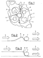
- Fig. 1
- den Kühlraum eines erfindungsgemäßen Zylinderkopfes in einer feuerdeckseitigen Ansicht in einer ersten Ausführungsvariante;
- Fig. 2
- einen Detailschnitt des Zylinderkopfes schematisch in einer Ausführungsvariante;
- Fig. 3
- einen Detailschnitt des Zylinderkopfes schematisch in einer anderen Ausführungsvariante;
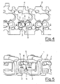
- Fig. 4
- den Kühlraum eines erfindungsgemäßen Zylinderkopfes in einer feuerdeckseitigen Ansicht in einer weiteren Ausführungsvariante; und
- Fig. 5
- den Kühlraum in einer Schrägansicht.
-
Fig. 1 zeigt in einer Kerndarstellung den Kühlraum 1 eines Zylinderkopfes 2 eine Brennkraftmaschine mit vier Gaswechselventilen pro Zylinder und einer zentralen Einspritzeinrichtung, wobei mit Bezugszeichen 3 die Bereiche der Auslassventile, mit Bezugszeichen 4 die Bereiche der Einlassventile und mit Bezugszeichen 5 der Bereich der zentralen Einspritzdüse bezeichnet ist. Über eine nicht weiter dargestellte Hauptzuflussöffnung gelangt Kühlmittel in den Kühlraum 1. Der Zylinderkopf 2 wird vom Kühlmittel in Längsrichtung zur Motorquerrichtung durchströmt, wobei die Pfeile S die Hauptströmungsrichtung andeuten. Quer zur Hauptströmung S mündet eine Nebenströmung N in den Kühlraum 1 ein, wobei die Nebenströmung N über eine Nebenzuflussöffnung 7 dem Hauptstrom S zugeführt wird. - Um Strömungsverluste im Bereich der Kreuzung zwischen Hauptströmung S und Nebenströmung N zu vermeiden, ist die Nebenzuflussöffnung 7 in einem strömungsabgewandten Bereich des Kühlraumes 1 angeordnet. Die Nebenzuflussöffnung 7 wird dabei durch eine Strömungsstörungsstelle 8 des Zylinderkopfes 2 vom Hauptstrom S abgedeckt. Die Strömungsstörungsstelle 8 kann dabei durch eine quer zur Hauptströmung S ausgebildete Querrippe 9 (
Fig. 2 ) oder eine Strömungsstufe 10 (Fig. 3 ) gebildet sein. Die Strömungsstörungsstelle 8 bewirkt eine Ablösung der Hauptströmung S und eine Ausbildung eines Bereiches mit geringer Strömungsgeschwindigkeit unmittelbar stromabwärts der Strömungsstörungsstelle 8. Der Nebenstrom N mündet somit in einem ungestörten, vom Hauptstrom geschützten Bereich des Kühlraumes 1 mit geringen Strömungsgeschwindigkeiten ein. Dadurch können Strömungsverluste durch Kreuzen der beiden Ströme S, N weitgehend vermieden werden.
Claims (4)
- Zylinderkopf (2) für eine Brennkraftmaschine mit zumindest einem Kühlraum (1), in welchem mindestens eine Haupt- und mindestens eine Nebenzuflussöffnung (7) einmündet, wobei die Nebenzuflussöffnung im Wesentlichen quer zu einer Hauptströmungsrichtung (S) im Kühlraum (1) einmündet, wobei die Nebenzuflussöffnung (7) in einem strömungsabgewandten Bereich des Zylinderkopfes (2) in den Kühlraum (1) einmündet und wobei die Nebenzuflussöffnung unmittelbar stromabwärts einer Strömungsstörungsstelle (8) in den Kühlraum (1) einmündet, dadurch gekennzeichnet, dass an der der Strömungsstörungsstelle (8) gegenüberliegenden Seite des Kühlraumes (1) die Wandkontur zur Erzielung eines gleichmäßigen Querschnittsverlaufes für die Hauptströmung der Strömungsstörungsstelle (8) nachgeformt ist.
- Zylinderkopf (2) nach Anspruch 1, dadurch gekennzeichnet, dass die Strömungsstörungsstelle (8) durch eine quer zur Hauptströmung (S) ausgebildete Rippe (9) gebildet ist.
- Zylinderkopf (2) nach Anspruch 1, dadurch gekennzeichnet, dass die Strömungsstörungsstelle (8) durch eine rückspringende Strömungsstufe (10) gebildet ist.
- Zylinderkopf (2) nach einem der Ansprüche 1 bis 3, dadurch gekennzeichnet, dass die Strömungsstörungsstelle (8) im Bereich des Bodens des Kühlraumes (1), vorzugsweise im Bereich des Feuerdeckes des Zylinderkopfes (2) angeordnet ist.
Priority Applications (1)
| Application Number | Priority Date | Filing Date | Title |
|---|---|---|---|
| PL06450083T PL1736660T3 (pl) | 2005-06-23 | 2006-06-22 | Głowica cylindrowa do silnika spalinowego |
Applications Claiming Priority (1)
| Application Number | Priority Date | Filing Date | Title |
|---|---|---|---|
| AT0106305A AT502089B1 (de) | 2005-06-23 | 2005-06-23 | Zylinderkopf für eine brennkraftmaschine |
Publications (3)
| Publication Number | Publication Date |
|---|---|
| EP1736660A2 EP1736660A2 (de) | 2006-12-27 |
| EP1736660A3 EP1736660A3 (de) | 2007-12-12 |
| EP1736660B1 true EP1736660B1 (de) | 2012-04-04 |
Family
ID=36954699
Family Applications (1)
| Application Number | Title | Priority Date | Filing Date |
|---|---|---|---|
| EP06450083A Active EP1736660B1 (de) | 2005-06-23 | 2006-06-22 | Zylinderkopf für eine Brennkraftmaschine |
Country Status (3)
| Country | Link |
|---|---|
| EP (1) | EP1736660B1 (de) |
| AT (2) | AT502089B1 (de) |
| PL (1) | PL1736660T3 (de) |
Family Cites Families (6)
| Publication number | Priority date | Publication date | Assignee | Title |
|---|---|---|---|---|
| GB766187A (en) * | 1953-11-26 | 1957-01-16 | Ricardo & Co Engineers | Improvements in detachable cylinder head constructions for liquid-cooled internal combustion engines |
| DE3208341A1 (de) * | 1982-03-09 | 1983-09-15 | Klöckner-Humboldt-Deutz AG, 5000 Köln | Zylinderkopf fuer eine wassergekuehlte brennkraftmaschine |
| JPH09324695A (ja) * | 1996-06-05 | 1997-12-16 | Daihatsu Motor Co Ltd | 内燃機関におけるシリンダヘッドの構造 |
| DE19644409C1 (de) * | 1996-10-25 | 1998-01-29 | Daimler Benz Ag | Zylinderkopf einer Mehrzylinder-Brennkraftmaschine |
| DE19943001C1 (de) * | 1999-09-09 | 2000-10-26 | Porsche Ag | Zylinderkopf für eine wassergekühlte Brennkraftmaschine |
| DE10237664A1 (de) * | 2002-08-16 | 2004-02-19 | Dr.Ing.H.C. F. Porsche Ag | Zylinderkopf für eine wassergekühlte mehrzylindrige Brennkraftmaschine |
-
2005
- 2005-06-23 AT AT0106305A patent/AT502089B1/de not_active IP Right Cessation
-
2006
- 2006-06-22 EP EP06450083A patent/EP1736660B1/de active Active
- 2006-06-22 PL PL06450083T patent/PL1736660T3/pl unknown
- 2006-06-22 AT AT06450083T patent/ATE552415T1/de active
Also Published As
| Publication number | Publication date |
|---|---|
| PL1736660T3 (pl) | 2012-09-28 |
| ATE552415T1 (de) | 2012-04-15 |
| AT502089B1 (de) | 2007-07-15 |
| EP1736660A3 (de) | 2007-12-12 |
| EP1736660A2 (de) | 2006-12-27 |
| AT502089A1 (de) | 2007-01-15 |
Similar Documents
| Publication | Publication Date | Title |
|---|---|---|
| AT506473B1 (de) | Zylinderkopf einer brennkraftmaschine | |
| DE10350394B4 (de) | Zylinderkopf für eine flüssigkeitsgekühlte Mehrzylinder-Brennkraftmaschine | |
| EP1884647B1 (de) | Flüssigkeitsgekühlter Zylinderkopf für eine Brennkraftmaschine | |
| WO2004001214A1 (de) | Gekühlter zylinderkopf für eine kolbenbrennkraftmaschine | |
| AT514087B1 (de) | Zylinderkopf für eine Brennkraftmaschine | |
| WO2011061248A1 (de) | Zylinderkopf für eine brennkraftmaschine | |
| EP3292293B1 (de) | Zylinderkopf für eine brennkraftmaschine | |
| EP1532359B1 (de) | Zylinderkopf für eine wassergekühlte mehrzylindrige brennkraftmaschine | |
| EP0819837B1 (de) | Kühlkreislauf einer Brennkraftmaschine | |
| EP1736660B1 (de) | Zylinderkopf für eine Brennkraftmaschine | |
| WO2020188071A1 (de) | Brennkraftmaschine mit zumindest einem zylinder | |
| WO2007051212A2 (de) | Zylinderkopf | |
| EP1083328A2 (de) | Zylinderkopf für eine wassergekühlte Brennkraftmaschine | |
| EP1972772B1 (de) | Zylinderkopf für eine flüssigkeitsgekühlte Brennkraftmaschine | |
| EP1329628B1 (de) | Zylinderdeckel mit einem Kühlkanalsystem für eine Hubkolbenbrennkraftmaschine | |
| AT516742B1 (de) | Brennkraftmaschine mit einem flüssiggekühlten zylinderblock | |
| WO2011113747A1 (de) | Zylinderkopf | |
| DE102020111055B3 (de) | Zylinderkopf mit einer Kühlkanalstruktur | |
| AT501229B1 (de) | Zylinderkopf | |
| AT526344B1 (de) | Flüssigkeitsgekühlter Zylinderkopf | |
| AT413860B (de) | Zylinderkopf für eine flüssigkeitsgekühlte mehrzylinder-brennkraftmaschine | |
| WO2018041552A1 (de) | Zylinderkopf für einen verbrennungsmotor | |
| AT500810B1 (de) | Zylinderkopf | |
| DE102015222859A1 (de) | Zylinderkopf einer Brennkraftmaschine mit integriertem Abgaskrümmer und Kühlmantel | |
| DE102012112904A1 (de) | Brennkraftmaschine mit einem Zylinderkopf |
Legal Events
| Date | Code | Title | Description |
|---|---|---|---|
| PUAI | Public reference made under article 153(3) epc to a published international application that has entered the european phase |
Free format text: ORIGINAL CODE: 0009012 |
|
| AK | Designated contracting states |
Kind code of ref document: A2 Designated state(s): AT BE BG CH CY CZ DE DK EE ES FI FR GB GR HU IE IS IT LI LT LU LV MC NL PL PT RO SE SI SK TR |
|
| AX | Request for extension of the european patent |
Extension state: AL BA HR MK YU |
|
| PUAL | Search report despatched |
Free format text: ORIGINAL CODE: 0009013 |
|
| AK | Designated contracting states |
Kind code of ref document: A3 Designated state(s): AT BE BG CH CY CZ DE DK EE ES FI FR GB GR HU IE IS IT LI LT LU LV MC NL PL PT RO SE SI SK TR |
|
| AX | Request for extension of the european patent |
Extension state: AL BA HR MK YU |
|
| 17P | Request for examination filed |
Effective date: 20080208 |
|
| 17Q | First examination report despatched |
Effective date: 20080327 |
|
| AKX | Designation fees paid |
Designated state(s): AT BE BG CH CY CZ DE DK EE ES FI FR GB GR HU IE IS IT LI LT LU LV MC NL PL PT RO SE SI SK TR |
|
| RAP1 | Party data changed (applicant data changed or rights of an application transferred) |
Owner name: MAN TRUCK & BUS AG |
|
| GRAP | Despatch of communication of intention to grant a patent |
Free format text: ORIGINAL CODE: EPIDOSNIGR1 |
|
| RTI1 | Title (correction) |
Free format text: CYLINDER HEAD FOR AN INTERNAL COMBUSTION ENGINE |
|
| GRAS | Grant fee paid |
Free format text: ORIGINAL CODE: EPIDOSNIGR3 |
|
| GRAA | (expected) grant |
Free format text: ORIGINAL CODE: 0009210 |
|
| AK | Designated contracting states |
Kind code of ref document: B1 Designated state(s): AT BE BG CH CY CZ DE DK EE ES FI FR GB GR HU IE IS IT LI LT LU LV MC NL PL PT RO SE SI SK TR |
|
| REG | Reference to a national code |
Ref country code: GB Ref legal event code: FG4D Free format text: NOT ENGLISH |
|
| REG | Reference to a national code |
Ref country code: CH Ref legal event code: EP |
|
| REG | Reference to a national code |
Ref country code: AT Ref legal event code: REF Ref document number: 552415 Country of ref document: AT Kind code of ref document: T Effective date: 20120415 |
|
| REG | Reference to a national code |
Ref country code: IE Ref legal event code: FG4D Free format text: LANGUAGE OF EP DOCUMENT: GERMAN |
|
| REG | Reference to a national code |
Ref country code: NL Ref legal event code: T3 |
|
| REG | Reference to a national code |
Ref country code: DE Ref legal event code: R096 Ref document number: 502006011236 Country of ref document: DE Effective date: 20120531 |
|
| REG | Reference to a national code |
Ref country code: SE Ref legal event code: TRGR |
|
| LTIE | Lt: invalidation of european patent or patent extension |
Effective date: 20120404 |
|
| REG | Reference to a national code |
Ref country code: PL Ref legal event code: T3 |
|
| PG25 | Lapsed in a contracting state [announced via postgrant information from national office to epo] |
Ref country code: FI Free format text: LAPSE BECAUSE OF FAILURE TO SUBMIT A TRANSLATION OF THE DESCRIPTION OR TO PAY THE FEE WITHIN THE PRESCRIBED TIME-LIMIT Effective date: 20120404 Ref country code: SI Free format text: LAPSE BECAUSE OF FAILURE TO SUBMIT A TRANSLATION OF THE DESCRIPTION OR TO PAY THE FEE WITHIN THE PRESCRIBED TIME-LIMIT Effective date: 20120404 Ref country code: IS Free format text: LAPSE BECAUSE OF FAILURE TO SUBMIT A TRANSLATION OF THE DESCRIPTION OR TO PAY THE FEE WITHIN THE PRESCRIBED TIME-LIMIT Effective date: 20120804 Ref country code: CY Free format text: LAPSE BECAUSE OF FAILURE TO SUBMIT A TRANSLATION OF THE DESCRIPTION OR TO PAY THE FEE WITHIN THE PRESCRIBED TIME-LIMIT Effective date: 20120404 Ref country code: LT Free format text: LAPSE BECAUSE OF FAILURE TO SUBMIT A TRANSLATION OF THE DESCRIPTION OR TO PAY THE FEE WITHIN THE PRESCRIBED TIME-LIMIT Effective date: 20120404 |
|
| PG25 | Lapsed in a contracting state [announced via postgrant information from national office to epo] |
Ref country code: GR Free format text: LAPSE BECAUSE OF FAILURE TO SUBMIT A TRANSLATION OF THE DESCRIPTION OR TO PAY THE FEE WITHIN THE PRESCRIBED TIME-LIMIT Effective date: 20120705 Ref country code: PT Free format text: LAPSE BECAUSE OF FAILURE TO SUBMIT A TRANSLATION OF THE DESCRIPTION OR TO PAY THE FEE WITHIN THE PRESCRIBED TIME-LIMIT Effective date: 20120806 Ref country code: LV Free format text: LAPSE BECAUSE OF FAILURE TO SUBMIT A TRANSLATION OF THE DESCRIPTION OR TO PAY THE FEE WITHIN THE PRESCRIBED TIME-LIMIT Effective date: 20120404 |
|
| BERE | Be: lapsed |
Owner name: MAN TRUCK & BUS A.G. Effective date: 20120630 |
|
| PG25 | Lapsed in a contracting state [announced via postgrant information from national office to epo] |
Ref country code: EE Free format text: LAPSE BECAUSE OF FAILURE TO SUBMIT A TRANSLATION OF THE DESCRIPTION OR TO PAY THE FEE WITHIN THE PRESCRIBED TIME-LIMIT Effective date: 20120404 Ref country code: DK Free format text: LAPSE BECAUSE OF FAILURE TO SUBMIT A TRANSLATION OF THE DESCRIPTION OR TO PAY THE FEE WITHIN THE PRESCRIBED TIME-LIMIT Effective date: 20120404 Ref country code: SK Free format text: LAPSE BECAUSE OF FAILURE TO SUBMIT A TRANSLATION OF THE DESCRIPTION OR TO PAY THE FEE WITHIN THE PRESCRIBED TIME-LIMIT Effective date: 20120404 Ref country code: CZ Free format text: LAPSE BECAUSE OF FAILURE TO SUBMIT A TRANSLATION OF THE DESCRIPTION OR TO PAY THE FEE WITHIN THE PRESCRIBED TIME-LIMIT Effective date: 20120404 Ref country code: RO Free format text: LAPSE BECAUSE OF FAILURE TO SUBMIT A TRANSLATION OF THE DESCRIPTION OR TO PAY THE FEE WITHIN THE PRESCRIBED TIME-LIMIT Effective date: 20120404 Ref country code: MC Free format text: LAPSE BECAUSE OF NON-PAYMENT OF DUE FEES Effective date: 20120630 |
|
| REG | Reference to a national code |
Ref country code: CH Ref legal event code: PL |
|
| PLBE | No opposition filed within time limit |
Free format text: ORIGINAL CODE: 0009261 |
|
| STAA | Information on the status of an ep patent application or granted ep patent |
Free format text: STATUS: NO OPPOSITION FILED WITHIN TIME LIMIT |
|
| REG | Reference to a national code |
Ref country code: CH Ref legal event code: PL |
|
| 26N | No opposition filed |
Effective date: 20130107 |
|
| GBPC | Gb: european patent ceased through non-payment of renewal fee |
Effective date: 20120704 |
|
| REG | Reference to a national code |
Ref country code: IE Ref legal event code: MM4A |
|
| PG25 | Lapsed in a contracting state [announced via postgrant information from national office to epo] |
Ref country code: ES Free format text: LAPSE BECAUSE OF FAILURE TO SUBMIT A TRANSLATION OF THE DESCRIPTION OR TO PAY THE FEE WITHIN THE PRESCRIBED TIME-LIMIT Effective date: 20120715 Ref country code: LI Free format text: LAPSE BECAUSE OF NON-PAYMENT OF DUE FEES Effective date: 20120630 Ref country code: GB Free format text: LAPSE BECAUSE OF NON-PAYMENT OF DUE FEES Effective date: 20120704 Ref country code: CH Free format text: LAPSE BECAUSE OF NON-PAYMENT OF DUE FEES Effective date: 20120630 Ref country code: BE Free format text: LAPSE BECAUSE OF NON-PAYMENT OF DUE FEES Effective date: 20120630 Ref country code: IE Free format text: LAPSE BECAUSE OF NON-PAYMENT OF DUE FEES Effective date: 20120622 |
|
| REG | Reference to a national code |
Ref country code: DE Ref legal event code: R097 Ref document number: 502006011236 Country of ref document: DE Effective date: 20130107 |
|
| PG25 | Lapsed in a contracting state [announced via postgrant information from national office to epo] |
Ref country code: BG Free format text: LAPSE BECAUSE OF FAILURE TO SUBMIT A TRANSLATION OF THE DESCRIPTION OR TO PAY THE FEE WITHIN THE PRESCRIBED TIME-LIMIT Effective date: 20120704 |
|
| REG | Reference to a national code |
Ref country code: AT Ref legal event code: MM01 Ref document number: 552415 Country of ref document: AT Kind code of ref document: T Effective date: 20120622 |
|
| PG25 | Lapsed in a contracting state [announced via postgrant information from national office to epo] |
Ref country code: AT Free format text: LAPSE BECAUSE OF NON-PAYMENT OF DUE FEES Effective date: 20120622 |
|
| PG25 | Lapsed in a contracting state [announced via postgrant information from national office to epo] |
Ref country code: LU Free format text: LAPSE BECAUSE OF NON-PAYMENT OF DUE FEES Effective date: 20120622 |
|
| PG25 | Lapsed in a contracting state [announced via postgrant information from national office to epo] |
Ref country code: HU Free format text: LAPSE BECAUSE OF FAILURE TO SUBMIT A TRANSLATION OF THE DESCRIPTION OR TO PAY THE FEE WITHIN THE PRESCRIBED TIME-LIMIT Effective date: 20060622 |
|
| REG | Reference to a national code |
Ref country code: FR Ref legal event code: PLFP Year of fee payment: 11 |
|
| REG | Reference to a national code |
Ref country code: FR Ref legal event code: PLFP Year of fee payment: 12 |
|
| REG | Reference to a national code |
Ref country code: FR Ref legal event code: PLFP Year of fee payment: 13 |
|
| REG | Reference to a national code |
Ref country code: DE Ref legal event code: R081 Ref document number: 502006011236 Country of ref document: DE Owner name: MAN TRUCK & BUS SE, DE Free format text: FORMER OWNER: MAN TRUCK & BUS AG, 80995 MUENCHEN, DE Ref country code: DE Ref legal event code: R082 Ref document number: 502006011236 Country of ref document: DE Representative=s name: BECKORD & NIEDLICH PATENTANWAELTE PARTG MBB, DE Ref country code: DE Ref legal event code: R082 Ref document number: 502006011236 Country of ref document: DE |
|
| REG | Reference to a national code |
Ref country code: DE Ref legal event code: R082 Ref document number: 502006011236 Country of ref document: DE |
|
| PGFP | Annual fee paid to national office [announced via postgrant information from national office to epo] |
Ref country code: SE Payment date: 20230317 Year of fee payment: 18 |
|
| PGFP | Annual fee paid to national office [announced via postgrant information from national office to epo] |
Ref country code: NL Payment date: 20230626 Year of fee payment: 18 Ref country code: FR Payment date: 20230622 Year of fee payment: 18 Ref country code: DE Payment date: 20230627 Year of fee payment: 18 |
|
| PGFP | Annual fee paid to national office [announced via postgrant information from national office to epo] |
Ref country code: TR Payment date: 20230609 Year of fee payment: 18 Ref country code: PL Payment date: 20230614 Year of fee payment: 18 |
|
| PGFP | Annual fee paid to national office [announced via postgrant information from national office to epo] |
Ref country code: IT Payment date: 20230620 Year of fee payment: 18 |
|
| REG | Reference to a national code |
Ref country code: DE Ref legal event code: R119 Ref document number: 502006011236 Country of ref document: DE |
|
| REG | Reference to a national code |
Ref country code: SE Ref legal event code: EUG |
|
| REG | Reference to a national code |
Ref country code: NL Ref legal event code: MM Effective date: 20240701 |
|
| PG25 | Lapsed in a contracting state [announced via postgrant information from national office to epo] |
Ref country code: NL Free format text: LAPSE BECAUSE OF NON-PAYMENT OF DUE FEES Effective date: 20240701 |
|
| PG25 | Lapsed in a contracting state [announced via postgrant information from national office to epo] |
Ref country code: NL Free format text: LAPSE BECAUSE OF NON-PAYMENT OF DUE FEES Effective date: 20240701 |
|
| PG25 | Lapsed in a contracting state [announced via postgrant information from national office to epo] |
Ref country code: DE Free format text: LAPSE BECAUSE OF NON-PAYMENT OF DUE FEES Effective date: 20250101 |
|
| PG25 | Lapsed in a contracting state [announced via postgrant information from national office to epo] |
Ref country code: FR Free format text: LAPSE BECAUSE OF NON-PAYMENT OF DUE FEES Effective date: 20240630 |
|
| PG25 | Lapsed in a contracting state [announced via postgrant information from national office to epo] |
Ref country code: IT Free format text: LAPSE BECAUSE OF NON-PAYMENT OF DUE FEES Effective date: 20240622 |
|
| PG25 | Lapsed in a contracting state [announced via postgrant information from national office to epo] |
Ref country code: SE Free format text: LAPSE BECAUSE OF NON-PAYMENT OF DUE FEES Effective date: 20240623 |
|
| PG25 | Lapsed in a contracting state [announced via postgrant information from national office to epo] |
Ref country code: PL Free format text: LAPSE BECAUSE OF NON-PAYMENT OF DUE FEES Effective date: 20240622 |