EP1736611A2 - Ein Befestigungshalter für eine Dachplatte - Google Patents
Ein Befestigungshalter für eine Dachplatte Download PDFInfo
- Publication number
- EP1736611A2 EP1736611A2 EP06445046A EP06445046A EP1736611A2 EP 1736611 A2 EP1736611 A2 EP 1736611A2 EP 06445046 A EP06445046 A EP 06445046A EP 06445046 A EP06445046 A EP 06445046A EP 1736611 A2 EP1736611 A2 EP 1736611A2
- Authority
- EP
- European Patent Office
- Prior art keywords
- base plate
- bracket
- tongue
- end portion
- bending line
- Prior art date
- Legal status (The legal status is an assumption and is not a legal conclusion. Google has not performed a legal analysis and makes no representation as to the accuracy of the status listed.)
- Granted
Links
Images

Classifications
-
- E—FIXED CONSTRUCTIONS
- E04—BUILDING
- E04D—ROOF COVERINGS; SKY-LIGHTS; GUTTERS; ROOF-WORKING TOOLS
- E04D3/00—Roof covering by making use of flat or curved slabs or stiff sheets
- E04D3/36—Connecting; Fastening
- E04D3/3601—Connecting; Fastening of roof covering supported by the roof structure with interposition of a insulating layer
-
- E—FIXED CONSTRUCTIONS
- E04—BUILDING
- E04D—ROOF COVERINGS; SKY-LIGHTS; GUTTERS; ROOF-WORKING TOOLS
- E04D3/00—Roof covering by making use of flat or curved slabs or stiff sheets
- E04D3/36—Connecting; Fastening
- E04D3/3601—Connecting; Fastening of roof covering supported by the roof structure with interposition of a insulating layer
- E04D3/3603—Connecting; Fastening of roof covering supported by the roof structure with interposition of a insulating layer the fastening means being screws or nails
-
- E—FIXED CONSTRUCTIONS
- E04—BUILDING
- E04D—ROOF COVERINGS; SKY-LIGHTS; GUTTERS; ROOF-WORKING TOOLS
- E04D3/00—Roof covering by making use of flat or curved slabs or stiff sheets
- E04D3/36—Connecting; Fastening
- E04D3/361—Connecting; Fastening by specially-profiled marginal portions of the slabs or sheets
- E04D3/362—Connecting; Fastening by specially-profiled marginal portions of the slabs or sheets by locking the edge of one slab or sheet within the profiled marginal portion of the adjacent slab or sheet, e.g. using separate connecting elements
-
- E—FIXED CONSTRUCTIONS
- E04—BUILDING
- E04D—ROOF COVERINGS; SKY-LIGHTS; GUTTERS; ROOF-WORKING TOOLS
- E04D3/00—Roof covering by making use of flat or curved slabs or stiff sheets
- E04D3/36—Connecting; Fastening
- E04D3/361—Connecting; Fastening by specially-profiled marginal portions of the slabs or sheets
- E04D2003/3615—Separate fastening elements fixed to the roof structure and consisting of parts permitting relative movement to each other, e.g. for thermal expansion
Definitions
- the present invention relates to a bracket for roofing sheet of the type described in the preamble to the appended independent claim 1.
- the side edges of long roofing sheets are turned up and shaped to a large flange or a low flange.
- a bracket is fitted close to the low flange.
- the low flange comprises a flange bent substantially perpendicularly from the main surface of the sheet, the outermost edge portion being folded in about 90° over the main surface of the sheet.
- the bracket has a base plate designed to rest on a roofing-sheet underlay and having one or more openings for attachment elements, such as screws, with which the base plate is secured to a load-bearing part of the roof structure.
- the base plate has a connecting that extends substantially perpendicularly from the extension plane of the base plate and has an upper portion bent round approximately 90° to extend over and close to the end portion of the low flange.
- the upper flange of the connecting tongue also comprises an end portion bent approximately 90° therefrom so that the connecting tongue acquires a channel profile, the concave side of which faces the plane of the base plate.
- Such a bracket is hooked over the low flange of the roofing sheet and secured with attachment elements (which may be pre-mounted on the base plate) to the load-bearing structure.
- the base plate has a relatively large surface area and rests on the heat-insulating layer which, in turn, is carried by the load-bearing structure, and the base plate therefore has teeth that engage in the thermal insulation to prevent the base plate from being displaced in relation to the surface of the thermal insulation. It is therefore usually necessary to linearly place the bracket on the low flange in a direction perpendicular to the roof surface. The end portion of the connection is then directed approximately perpendicularly to the surface of the roof. It is desirable to be able to fold in the end portion of the connecting tongue underneath the end flange of the low flange in order to temporarily retain the bracket in the correct position on the low flange until the attachment elements of the bracket can be fitted.
- the problem is that the end portion of the connecting tongue should have a length along the bending line that gives the end portion appropriate bending resistance as regards the folding operation or bending in of the end portion, so that the connecting tongue acquires a stable connection to the roofing sheets.
- the bending resistance necessary in practice means that the sheet-metal worker cannot in practice bend in the end portion with his hand/fingers but must use a folding tool for the operation.
- One object of the invention is therefore to provide a bracket of the type mentioned which makes it possible to partially or entirely eliminate said inconveniences.
- the invention entails the end portion of the flange tongue having a cut from its end edge to the bending region of the end portion, the cut being located between the side edges of the end portion.
- a manually bendable flap is thus established from the end portion and this flap can relatively easily be bent with the fingers under the end portion to temporarily secure it to the edge portion, parallel to the flange, of a low flange.
- the position of the cut can be chosen in order to produce a flap where the length of the bending line offers suitably low bending resistance for the temporary manual bending of the flap.
- the cut is inclined towards the bending line of the end portion so that the flap has relatively large breadth along the end edge of the end portion and relatively slight breadth along its bending line so that the operator's finger has a relatively large contact surface with the flap whereas the flap acquires a relatively short bending line.
- the bracket may be in the form of a fixed bracket or a sliding bracket.
- the connecting tongue is connected to the base plate with a sliding joint that permits the tongue to be displaced in a direction substantially parallel to the final plane of the base plate.
- the bending lines are substantially parallel to each other and parallel to the main surface of the base plate of the bracket so as to be parallel with the main surface of the roofing sheets and with the longitudinal direction of the roofing sheets.
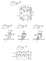
- Figures 1-3 illustrate a bracket 1 comprising a base plate 2 resting on the upper surface of a layer 3 of heat-insulating material 3 of mineral wool, for instance.
- the layer 3 rests in turn on a load-bearing roof structure 4 of plywood, wood, corrugated sheet-metal or the like.
- the base plate 2 is shown to have downwardly directed teeth 5 in the form of triangular flaps, for instance, which have been cut and folded out of the sheet-metal forming the base plate 2.
- the plate 2 is also provided with recessed openings 6 for assembly screws 7 which are secured in the load-bearing roof structure, e.g. the layer 4.
- the teeth may have a height of 1-2 cm, for instance, and serve to prevent the plate 2 from slipping in its plane in relation to the insulation 3.
- the plate 2 has a connecting tongue 10 that is preferably made out of a metallic sheet material.
- the tongue is directed substantially perpendicularly to the plate 2 and extends along the side edge near by.
- the tongue 10 is provided with an upper end section 11 that is folded out 90° away from the base plate 2.
- the section 11 has an outer edge portion 12 that is folded down approximately 90°.
- a cross section is also shown through an elongate roofing sheet 20, both side edges of which are folded up and shaped to a low flange 21 and a large flange 25, respectively.
- the low flange 21 comprises a flange 22 folded substantially perpendicularly up from the main surface of the plate, the upper end portion of the flange being folded in approximately 90° over the plate 20.
- the section 23 is received under the section 11 of the tongue 10, as shown.
- the large flange comprises a side edge flange 26 of the plate 20, folded up approximately 90°.
- the flange 26 has a portion 27 bent outwardly approximately 90°, the end portion 28 being turned down approximately 90°.
- the tongue 10 is shown connected to the base plate 2 by a sliding joint 30. Alternatively, if the tongue 10 does not need to be displaceable in the longitudinal direction of the plate 20, the tongue 10 may be connected to the plate 2.
- the sliding joint 30 is shown with a turned-up edge flange 31 of the base plate 2, the upper end portion of the flange 31 being folded around approximately 180°.
- the lower end portion 34 of the tongue 10 is also shown folded 180° in order to engage in the folded part 32 of the edge portion 31 and the ends of the flange 31 may possibly be clamped together to prevent the tongue 10 from sliding off the sliding joint part of the roof tile.
- Figure 2 shows the end section 12 with a cut 124 from its free end edge 120 to the vicinity of the bending line 40 of the section 12.
- the section 12 is thus divided into two tongues 121, 122.
- one flap 121 can be manually folded in under the low flange 21, so that the bracket 1 is temporarily joined to the low flange 21 of the sheet 20 after the bracket 1 has been placed on its underlay 3 in a normal alignment to the underlay surface.
- the screws 7 can then be inserted through the openings 6 and fitted in the load-bearing structure 4.
- FIG 4 shows schematically a detail corresponding to Figure 1, of the low flange 21 with a bracket tongue 10 temporarily connected to it, the flap 121 being shown folded in under the end section 23 of the low flange whereas the remaining flap 122 is still perpendicular to the main surface of the sheet 20.
- Figure 5 illustrates the large flange 25 of another sheet 20 having been applied over the temporary joint according to Figure 4.
- the joined adjacent roofing sheets are then folded in conventional manner by means of flange rods or flanging tools.
- the finished single flanging shown schematically in Figure 6 is thus obtained.
- the single flange can then be folded around 90° if a double flange is desired, to ensure tightness.
- the slit 24 is placed to give the temporary securing tongue 21 a suitably short connecting stretch to the tongue along a line parallel to the bending line 40 and is located close to this so that it can be manually bent by an operator to produce the temporary connection to the low flange of the roofing sheet. Furthermore, the cut 24 is shown inclined towards the bending line 40 so that the tongue 21 has a relatively large breadth near the outer end edges of the tongue to allow a comfortable grip for the fingers, while the bending line of the flap 121 has suitably slight length.
- the remaining flap 122 is folded in under the end section 23 of the low flange, together with the end section 28 of the large flange, using conventional folding tools/machines.
- the bracket in accordance with the invention has been shown in connection with a special bracket design in which the base plate 2 and securing screws 7 are adapted for assembly on a heat-insulating layer 3.
- the plate 2 may have considerably less area and may also lack teeth 5 when it is to be mounted directly on a stable underlay, such as planks, plywood or corrugated sheet-metal.
- the end portion 12 of the sliding tongue is relatively short along the bending line 40 the problem may arise that the end portion 12 offers a troublesome bending resistance along the line 40 during the folding operation, i.e. bending in the end portion 12 under the end section of the low flange. In that case it may be desirable to widen the slit 124, at least in the proximity of the bending line 40 and possibly all the way out to the end edge 120 so that the end portion 12 is in the shape of separate tongues 121, 122 along the bending line.
- the end portion 12 may be provided with several separate slits 124 along the bending line 40 which may thus be widened to form several separate tongues along the bending line 40, thereby offering suitable resistance to the folding operation if the end portion shall be of considerable length.
Landscapes
- Engineering & Computer Science (AREA)
- Mechanical Engineering (AREA)
- Architecture (AREA)
- Civil Engineering (AREA)
- Structural Engineering (AREA)
- Roof Covering Using Slabs Or Stiff Sheets (AREA)
- Vehicle Interior And Exterior Ornaments, Soundproofing, And Insulation (AREA)
- Body Structure For Vehicles (AREA)
Applications Claiming Priority (1)
| Application Number | Priority Date | Filing Date | Title |
|---|---|---|---|
| SE0501456A SE528744C2 (sv) | 2005-06-22 | 2005-06-22 | Klammer för takplåt |
Publications (3)
| Publication Number | Publication Date |
|---|---|
| EP1736611A2 true EP1736611A2 (de) | 2006-12-27 |
| EP1736611A3 EP1736611A3 (de) | 2009-01-07 |
| EP1736611B1 EP1736611B1 (de) | 2010-03-31 |
Family
ID=36950605
Family Applications (1)
| Application Number | Title | Priority Date | Filing Date |
|---|---|---|---|
| EP06445046A Ceased EP1736611B1 (de) | 2005-06-22 | 2006-06-15 | Ein Befestigungshalter für eine Dachplatte |
Country Status (4)
| Country | Link |
|---|---|
| EP (1) | EP1736611B1 (de) |
| AT (1) | ATE462848T1 (de) |
| DE (1) | DE602006013225D1 (de) |
| SE (1) | SE528744C2 (de) |
Citations (1)
| Publication number | Priority date | Publication date | Assignee | Title |
|---|---|---|---|---|
| JPH11193603A (ja) | 1997-12-27 | 1999-07-21 | Daiwa House Ind Co Ltd | 屋根葺き構造およびその吊り子 |
Family Cites Families (2)
| Publication number | Priority date | Publication date | Assignee | Title |
|---|---|---|---|---|
| SE442033B (sv) * | 1982-07-08 | 1985-11-25 | Bengt Johansson | Glidklammer |
| GB2287044A (en) * | 1994-02-26 | 1995-09-06 | Bjarne Svanberg | Sliding bracket and roof structure comprising such a sliding bracket |
-
2005
- 2005-06-22 SE SE0501456A patent/SE528744C2/sv not_active IP Right Cessation
-
2006
- 2006-06-15 EP EP06445046A patent/EP1736611B1/de not_active Ceased
- 2006-06-15 AT AT06445046T patent/ATE462848T1/de not_active IP Right Cessation
- 2006-06-15 DE DE602006013225T patent/DE602006013225D1/de active Active
Patent Citations (1)
| Publication number | Priority date | Publication date | Assignee | Title |
|---|---|---|---|---|
| JPH11193603A (ja) | 1997-12-27 | 1999-07-21 | Daiwa House Ind Co Ltd | 屋根葺き構造およびその吊り子 |
Also Published As
| Publication number | Publication date |
|---|---|
| EP1736611A3 (de) | 2009-01-07 |
| SE528744C2 (sv) | 2007-02-06 |
| EP1736611B1 (de) | 2010-03-31 |
| SE0501456L (sv) | 2006-12-23 |
| ATE462848T1 (de) | 2010-04-15 |
| DE602006013225D1 (de) | 2010-05-12 |
Similar Documents
| Publication | Publication Date | Title |
|---|---|---|
| EP0687337B1 (de) | Schraegdach mit dachziegeln und dachklammer zur anwendung in solchem dach | |
| US9650787B2 (en) | Single layer foldable reinforced bullnose hip and ridge cap shingle | |
| CZ20001712A3 (cs) | Souprava prvků z foliového materiálu pro lemování a způsob lemování | |
| AU2017247781B2 (en) | Resilient fixing element and a skirting board fixing system comprising a skirting board and such a fixing element | |
| US20100000171A1 (en) | Sheet metal cladding panel | |
| EP1736611B1 (de) | Ein Befestigungshalter für eine Dachplatte | |
| KR101570104B1 (ko) | 건축물 지붕 및 외벽용 마감재 | |
| EP3453811B1 (de) | Verfahren zur installation eines fensterrahmens in einer schrägen dachstruktur und dichtkragen zur verwendung bei der installation eines fensterrahmens | |
| US20210010268A1 (en) | Roofing Trim Saddle System and Method of Installing | |
| US4318261A (en) | Roof panel and hold down clip therefor | |
| EP3575509B1 (de) | Verfahren zur bereitstellung einer montagehilfe, montagehilfe, die zur verwendung bei der montage eines fensterrahmens in einer dachkonstruktion eines gebäudes angepasst ist, und kit mit einer montagehilfe | |
| EP3919703A1 (de) | Dachpanel | |
| EP2473686A1 (de) | Vorrichtung zur führung eines rohrs von grossem querschnitt durch ein dach | |
| RU2333325C2 (ru) | Ветровая скоба | |
| EP0832337B1 (de) | Dachrinnenklemme und verfahren zu deren herstellung und montage | |
| JP2799962B2 (ja) | けらば包み材 | |
| EP2568093A1 (de) | Klammer zur Befestigung von Blechmetallteilen an Dachbalken und dergleichen | |
| EP0367742B1 (de) | Verbindung von Dachdeckplatten | |
| EP2738319B1 (de) | Klammer zur Befestigung von Metallblechen an Balken von Überdachungsflächen, Dächern oder ähnlichem | |
| EP1905917B1 (de) | Schrägdach und Schrägdachabdeckungsverfahren | |
| JP7421684B1 (ja) | 垂木ユニットおよび屋根構造 | |
| JP2005188197A (ja) | 屋根材 | |
| JP3059190U (ja) | 瓦止め具 | |
| JPH0686756B2 (ja) | 屋根構造における葺替屋根用の横葺き屋根板 | |
| JP3345251B2 (ja) | 横葺屋根用化粧瓦棒 |
Legal Events
| Date | Code | Title | Description |
|---|---|---|---|
| PUAI | Public reference made under article 153(3) epc to a published international application that has entered the european phase |
Free format text: ORIGINAL CODE: 0009012 |
|
| AK | Designated contracting states |
Kind code of ref document: A2 Designated state(s): AT BE BG CH CY CZ DE DK EE ES FI FR GB GR HU IE IS IT LI LT LU LV MC NL PL PT RO SE SI SK TR |
|
| AX | Request for extension of the european patent |
Extension state: AL BA HR MK YU |
|
| 17P | Request for examination filed |
Effective date: 20070627 |
|
| PUAL | Search report despatched |
Free format text: ORIGINAL CODE: 0009013 |
|
| AK | Designated contracting states |
Kind code of ref document: A3 Designated state(s): AT BE BG CH CY CZ DE DK EE ES FI FR GB GR HU IE IS IT LI LT LU LV MC NL PL PT RO SE SI SK TR |
|
| AX | Request for extension of the european patent |
Extension state: AL BA HR MK RS |
|
| AKX | Designation fees paid |
Designated state(s): AT BE BG CH CY CZ DE DK EE ES FI FR GB GR HU IE IS IT LI LT LU LV MC NL PL PT RO SE SI SK TR |
|
| GRAP | Despatch of communication of intention to grant a patent |
Free format text: ORIGINAL CODE: EPIDOSNIGR1 |
|
| GRAS | Grant fee paid |
Free format text: ORIGINAL CODE: EPIDOSNIGR3 |
|
| GRAA | (expected) grant |
Free format text: ORIGINAL CODE: 0009210 |
|
| AK | Designated contracting states |
Kind code of ref document: B1 Designated state(s): AT BE BG CH CY CZ DE DK EE ES FI FR GB GR HU IE IS IT LI LT LU LV MC NL PL PT RO SE SI SK TR |
|
| REG | Reference to a national code |
Ref country code: GB Ref legal event code: FG4D Ref country code: CH Ref legal event code: EP |
|
| REG | Reference to a national code |
Ref country code: IE Ref legal event code: FG4D |
|
| REF | Corresponds to: |
Ref document number: 602006013225 Country of ref document: DE Date of ref document: 20100512 Kind code of ref document: P |
|
| REG | Reference to a national code |
Ref country code: DE Ref legal event code: R096 Ref document number: 602006013225 Country of ref document: DE Effective date: 20100512 |
|
| REG | Reference to a national code |
Ref country code: NL Ref legal event code: T3 |
|
| PG25 | Lapsed in a contracting state [announced via postgrant information from national office to epo] |
Ref country code: LT Free format text: LAPSE BECAUSE OF FAILURE TO SUBMIT A TRANSLATION OF THE DESCRIPTION OR TO PAY THE FEE WITHIN THE PRESCRIBED TIME-LIMIT Effective date: 20100331 |
|
| LTIE | Lt: invalidation of european patent or patent extension |
Effective date: 20100331 |
|
| PG25 | Lapsed in a contracting state [announced via postgrant information from national office to epo] |
Ref country code: LV Free format text: LAPSE BECAUSE OF FAILURE TO SUBMIT A TRANSLATION OF THE DESCRIPTION OR TO PAY THE FEE WITHIN THE PRESCRIBED TIME-LIMIT Effective date: 20100331 Ref country code: FI Free format text: LAPSE BECAUSE OF FAILURE TO SUBMIT A TRANSLATION OF THE DESCRIPTION OR TO PAY THE FEE WITHIN THE PRESCRIBED TIME-LIMIT Effective date: 20100331 Ref country code: PL Free format text: LAPSE BECAUSE OF FAILURE TO SUBMIT A TRANSLATION OF THE DESCRIPTION OR TO PAY THE FEE WITHIN THE PRESCRIBED TIME-LIMIT Effective date: 20100331 Ref country code: SI Free format text: LAPSE BECAUSE OF FAILURE TO SUBMIT A TRANSLATION OF THE DESCRIPTION OR TO PAY THE FEE WITHIN THE PRESCRIBED TIME-LIMIT Effective date: 20100331 Ref country code: AT Free format text: LAPSE BECAUSE OF FAILURE TO SUBMIT A TRANSLATION OF THE DESCRIPTION OR TO PAY THE FEE WITHIN THE PRESCRIBED TIME-LIMIT Effective date: 20100331 |
|
| PG25 | Lapsed in a contracting state [announced via postgrant information from national office to epo] |
Ref country code: CY Free format text: LAPSE BECAUSE OF FAILURE TO SUBMIT A TRANSLATION OF THE DESCRIPTION OR TO PAY THE FEE WITHIN THE PRESCRIBED TIME-LIMIT Effective date: 20100331 Ref country code: BE Free format text: LAPSE BECAUSE OF FAILURE TO SUBMIT A TRANSLATION OF THE DESCRIPTION OR TO PAY THE FEE WITHIN THE PRESCRIBED TIME-LIMIT Effective date: 20100331 Ref country code: RO Free format text: LAPSE BECAUSE OF FAILURE TO SUBMIT A TRANSLATION OF THE DESCRIPTION OR TO PAY THE FEE WITHIN THE PRESCRIBED TIME-LIMIT Effective date: 20100331 Ref country code: EE Free format text: LAPSE BECAUSE OF FAILURE TO SUBMIT A TRANSLATION OF THE DESCRIPTION OR TO PAY THE FEE WITHIN THE PRESCRIBED TIME-LIMIT Effective date: 20100331 Ref country code: ES Free format text: LAPSE BECAUSE OF FAILURE TO SUBMIT A TRANSLATION OF THE DESCRIPTION OR TO PAY THE FEE WITHIN THE PRESCRIBED TIME-LIMIT Effective date: 20100712 Ref country code: SE Free format text: LAPSE BECAUSE OF FAILURE TO SUBMIT A TRANSLATION OF THE DESCRIPTION OR TO PAY THE FEE WITHIN THE PRESCRIBED TIME-LIMIT Effective date: 20100331 |
|
| PG25 | Lapsed in a contracting state [announced via postgrant information from national office to epo] |
Ref country code: CZ Free format text: LAPSE BECAUSE OF FAILURE TO SUBMIT A TRANSLATION OF THE DESCRIPTION OR TO PAY THE FEE WITHIN THE PRESCRIBED TIME-LIMIT Effective date: 20100331 Ref country code: IS Free format text: LAPSE BECAUSE OF FAILURE TO SUBMIT A TRANSLATION OF THE DESCRIPTION OR TO PAY THE FEE WITHIN THE PRESCRIBED TIME-LIMIT Effective date: 20100731 Ref country code: SK Free format text: LAPSE BECAUSE OF FAILURE TO SUBMIT A TRANSLATION OF THE DESCRIPTION OR TO PAY THE FEE WITHIN THE PRESCRIBED TIME-LIMIT Effective date: 20100331 |
|
| PG25 | Lapsed in a contracting state [announced via postgrant information from national office to epo] |
Ref country code: MC Free format text: LAPSE BECAUSE OF NON-PAYMENT OF DUE FEES Effective date: 20100630 Ref country code: DK Free format text: LAPSE BECAUSE OF FAILURE TO SUBMIT A TRANSLATION OF THE DESCRIPTION OR TO PAY THE FEE WITHIN THE PRESCRIBED TIME-LIMIT Effective date: 20100331 Ref country code: PT Free format text: LAPSE BECAUSE OF FAILURE TO SUBMIT A TRANSLATION OF THE DESCRIPTION OR TO PAY THE FEE WITHIN THE PRESCRIBED TIME-LIMIT Effective date: 20100802 |
|
| REG | Reference to a national code |
Ref country code: CH Ref legal event code: PL |
|
| PLBE | No opposition filed within time limit |
Free format text: ORIGINAL CODE: 0009261 |
|
| STAA | Information on the status of an ep patent application or granted ep patent |
Free format text: STATUS: NO OPPOSITION FILED WITHIN TIME LIMIT |
|
| 26N | No opposition filed |
Effective date: 20110104 |
|
| PG25 | Lapsed in a contracting state [announced via postgrant information from national office to epo] |
Ref country code: IT Free format text: LAPSE BECAUSE OF FAILURE TO SUBMIT A TRANSLATION OF THE DESCRIPTION OR TO PAY THE FEE WITHIN THE PRESCRIBED TIME-LIMIT Effective date: 20100331 |
|
| REG | Reference to a national code |
Ref country code: DE Ref legal event code: R097 Ref document number: 602006013225 Country of ref document: DE Effective date: 20110104 |
|
| PG25 | Lapsed in a contracting state [announced via postgrant information from national office to epo] |
Ref country code: CH Free format text: LAPSE BECAUSE OF NON-PAYMENT OF DUE FEES Effective date: 20100630 Ref country code: LI Free format text: LAPSE BECAUSE OF NON-PAYMENT OF DUE FEES Effective date: 20100630 Ref country code: IE Free format text: LAPSE BECAUSE OF NON-PAYMENT OF DUE FEES Effective date: 20100615 |
|
| PG25 | Lapsed in a contracting state [announced via postgrant information from national office to epo] |
Ref country code: BG Free format text: LAPSE BECAUSE OF FAILURE TO SUBMIT A TRANSLATION OF THE DESCRIPTION OR TO PAY THE FEE WITHIN THE PRESCRIBED TIME-LIMIT Effective date: 20100331 Ref country code: HU Free format text: LAPSE BECAUSE OF FAILURE TO SUBMIT A TRANSLATION OF THE DESCRIPTION OR TO PAY THE FEE WITHIN THE PRESCRIBED TIME-LIMIT Effective date: 20101001 Ref country code: LU Free format text: LAPSE BECAUSE OF NON-PAYMENT OF DUE FEES Effective date: 20100615 |
|
| PG25 | Lapsed in a contracting state [announced via postgrant information from national office to epo] |
Ref country code: TR Free format text: LAPSE BECAUSE OF FAILURE TO SUBMIT A TRANSLATION OF THE DESCRIPTION OR TO PAY THE FEE WITHIN THE PRESCRIBED TIME-LIMIT Effective date: 20100331 |
|
| PG25 | Lapsed in a contracting state [announced via postgrant information from national office to epo] |
Ref country code: BG Free format text: LAPSE BECAUSE OF FAILURE TO SUBMIT A TRANSLATION OF THE DESCRIPTION OR TO PAY THE FEE WITHIN THE PRESCRIBED TIME-LIMIT Effective date: 20100630 |
|
| PG25 | Lapsed in a contracting state [announced via postgrant information from national office to epo] |
Ref country code: GR Free format text: LAPSE BECAUSE OF FAILURE TO SUBMIT A TRANSLATION OF THE DESCRIPTION OR TO PAY THE FEE WITHIN THE PRESCRIBED TIME-LIMIT Effective date: 20100331 |
|
| REG | Reference to a national code |
Ref country code: FR Ref legal event code: PLFP Year of fee payment: 11 |
|
| REG | Reference to a national code |
Ref country code: FR Ref legal event code: PLFP Year of fee payment: 12 |
|
| REG | Reference to a national code |
Ref country code: FR Ref legal event code: PLFP Year of fee payment: 13 |
|
| P01 | Opt-out of the competence of the unified patent court (upc) registered |
Effective date: 20230530 |
|
| PGFP | Annual fee paid to national office [announced via postgrant information from national office to epo] |
Ref country code: NL Payment date: 20230516 Year of fee payment: 18 Ref country code: FR Payment date: 20230522 Year of fee payment: 18 Ref country code: DE Payment date: 20230522 Year of fee payment: 18 |
|
| PGFP | Annual fee paid to national office [announced via postgrant information from national office to epo] |
Ref country code: GB Payment date: 20230516 Year of fee payment: 18 |
|
| REG | Reference to a national code |
Ref country code: DE Ref legal event code: R119 Ref document number: 602006013225 Country of ref document: DE |
|
| REG | Reference to a national code |
Ref country code: NL Ref legal event code: MM Effective date: 20240701 |
|
| GBPC | Gb: european patent ceased through non-payment of renewal fee |
Effective date: 20240615 |
|
| PG25 | Lapsed in a contracting state [announced via postgrant information from national office to epo] |
Ref country code: NL Free format text: LAPSE BECAUSE OF NON-PAYMENT OF DUE FEES Effective date: 20240701 |
|
| PG25 | Lapsed in a contracting state [announced via postgrant information from national office to epo] |
Ref country code: NL Free format text: LAPSE BECAUSE OF NON-PAYMENT OF DUE FEES Effective date: 20240701 |
|
| PG25 | Lapsed in a contracting state [announced via postgrant information from national office to epo] |
Ref country code: DE Free format text: LAPSE BECAUSE OF NON-PAYMENT OF DUE FEES Effective date: 20250101 |
|
| PG25 | Lapsed in a contracting state [announced via postgrant information from national office to epo] |
Ref country code: FR Free format text: LAPSE BECAUSE OF NON-PAYMENT OF DUE FEES Effective date: 20240630 |
|
| PG25 | Lapsed in a contracting state [announced via postgrant information from national office to epo] |
Ref country code: GB Free format text: LAPSE BECAUSE OF NON-PAYMENT OF DUE FEES Effective date: 20240615 |