EP1734612A2 - Device for connecting cables - Google Patents
Device for connecting cables Download PDFInfo
- Publication number
- EP1734612A2 EP1734612A2 EP06115502A EP06115502A EP1734612A2 EP 1734612 A2 EP1734612 A2 EP 1734612A2 EP 06115502 A EP06115502 A EP 06115502A EP 06115502 A EP06115502 A EP 06115502A EP 1734612 A2 EP1734612 A2 EP 1734612A2
- Authority
- EP
- European Patent Office
- Prior art keywords
- connecting device
- base
- screw
- base housing
- housing
- Prior art date
- Legal status (The legal status is an assumption and is not a legal conclusion. Google has not performed a legal analysis and makes no representation as to the accuracy of the status listed.)
- Granted
Links
Images


Classifications
-
- H—ELECTRICITY
- H01—ELECTRIC ELEMENTS
- H01R—ELECTRICALLY-CONDUCTIVE CONNECTIONS; STRUCTURAL ASSOCIATIONS OF A PLURALITY OF MUTUALLY-INSULATED ELECTRICAL CONNECTING ELEMENTS; COUPLING DEVICES; CURRENT COLLECTORS
- H01R4/00—Electrically-conductive connections between two or more conductive members in direct contact, i.e. touching one another; Means for effecting or maintaining such contact; Electrically-conductive connections having two or more spaced connecting locations for conductors and using contact members penetrating insulation
- H01R4/24—Connections using contact members penetrating or cutting insulation or cable strands
- H01R4/2404—Connections using contact members penetrating or cutting insulation or cable strands the contact members having teeth, prongs, pins or needles penetrating the insulation
- H01R4/2408—Connections using contact members penetrating or cutting insulation or cable strands the contact members having teeth, prongs, pins or needles penetrating the insulation actuated by clamping screws
-
- H—ELECTRICITY
- H01—ELECTRIC ELEMENTS
- H01R—ELECTRICALLY-CONDUCTIVE CONNECTIONS; STRUCTURAL ASSOCIATIONS OF A PLURALITY OF MUTUALLY-INSULATED ELECTRICAL CONNECTING ELEMENTS; COUPLING DEVICES; CURRENT COLLECTORS
- H01R4/00—Electrically-conductive connections between two or more conductive members in direct contact, i.e. touching one another; Means for effecting or maintaining such contact; Electrically-conductive connections having two or more spaced connecting locations for conductors and using contact members penetrating insulation
- H01R4/28—Clamped connections, spring connections
- H01R4/30—Clamped connections, spring connections utilising a screw or nut clamping member
- H01R4/307—Clamped connections, spring connections utilising a screw or nut clamping member characterised by the thread of the screw or nut
Definitions
- the invention relates to a connection device according to the preamble of claim 1.
- connection device for a lower protection class such as IP20, which is sufficient for many applications.
- This connection device should be inexpensive to produce and still allow a simple and secure contact preferably also of continuous cables in particular in the standard ASI.
- connection devices are the object of the invention.
- the actuator is designed in several parts and has a screw on which acts on a displaceably guided in the base housing base element with which the cable to be contacted in or on the insulation-penetrating contacts can be pressed.
- the pre-loading for the cable is particularly advantageous, preferably on the base housing or on the base part of the actuating device, which secures and fixes the cable before it is contacted by the insulation-penetrating contacts.
- 1a shows an illustration of a section of a continuous flat cable 1 which can be wired in all the embodiments shown, with two conductors 2, 3 arranged parallel to one another and embedded in a surrounding jacket 4 made of insulating material.
- the Isolierstoffmantel 4 is formed contoured and has on the one hand upper and lower notches 5, 6 between the conductors 2, 3 and on the other hand a web 7 for polarization or optical discrimination of the two conductors 2, 3rd
- the connecting devices 8 each have a base housing 9 made of insulating material and a multi-part actuator 10, which serves to press the flat cable 1 and the two conductors 2, 3 in isolations commentarydringende contacts 11, 12 - here forked with contact blades - in the base housing 9.
- the insulation-penetrating contacts can also be designed as insulation-piercing contacts-also called piercing contacts-which is particularly advantageous in the case of multi-core conductors (FIGS. 2 to 12).
- the insulation piercing contacts 11,12 of Figure 1 are each provided in a muzzle-like region 13 with cutting for insulation penetration and have a contact slot 14 for contacting the conductors.
- the two IDC contacts 11,12 are similarly formed and arranged offset in the base housing 9 in the conductor direction axially and radially to each other. They are also here in an advantageous and cost-effective manner integrally connected via busbar sections 15 with contact tulips 16, which protrude to connect external (not shown here) head in an outwardly open collar 17 of the housing 8, with a corresponding socket part with contact pins (not here shown) can be plugged together.
- the actuator 10 is movable relative to the base housing 9 and at least in an open position and in a closed position after insertion of the cable 1 positionable, which simplifies handling.
- the cable can preferably also be pre-locked on the base housing 9 or on the actuating device 10.
- the basic housing 9 of Fig. 1 is sleeve-like, here cylindrical, formed and provided with a lateral slot 18 into which the flat cable is inserted.
- the actuating device 10 has a cylindrical base body 19 in the manner of a sliding element which is laterally also provided with a slot 20 and which is telescopically guided in an axial opening or bore 21 of the base housing 9 slidably.
- the displacement of the base body 19 in the opening 21 is realized by means of a screw which cooperates with a thread on or in the base housing 9.
- the screw is realized here as a cover 22 which is designed in the manner of a screw cap which has an internal thread and cooperates with a corresponding external thread 23 of the base housing 9.
- FIGS. 2 to 11 show exemplary embodiments in which the base housing 9, which is preferably made of two pieces for assembly reasons, has two outer surfaces aligned at right angles to one another with two housing halves which can be locked together. Other shapes are also conceivable.
- the illustrated embodiment is particularly compact and easy to install.
- the basic housing 9 of Figure 2 which in turn consists of insulating plastic, as the embodiment of FIG. 1, the lateral slot 18, in which the flat cable 1 is inserted.
- the actuator 10 in turn has a slide-like base and actuator body 19 which is also provided laterally with the slot 20 and which is guided telescopically in the bore 21 of the base housing 9 perpendicular to the flat cable to be contacted.
- the displacement of the base or operating body 19 in the opening 21 is not here as in Fig. 1 with a lid but by means of a screw 24 as a screw - see also Fig. 9 - realized, which has an external thread 25 and with a corresponding Internal thread 26 cooperates in a first axial region of the bore 21 of the base housing 9.
- the slot 18 in the base housing 9 has a greater axial extent perpendicular to the extension of the flat cable than the slot 20 in the base body 19 in order to realize a sufficient displaceability of the cable.
- the contacts are configured here as insulation piercing piercing contacts 30, to each of which a conductor pin 31 connects, each projecting from the base housing 9 and where the base housing 9 is mounted on a circuit board (not shown here).
- the conductor pins can be straight or angular (FIGS. 1, 11), which makes it possible to implement various embodiments in order to align the connection device on the printed circuit board either laterally or vertically upwards.
- the piercing contacts pass through holes or slots 32 in the base body and are fixed in the base housing, so that the base body is displaceable on the piercing contacts.
- the basic housing 9 with relatively large planes - here mutually perpendicular - outer surfaces is ideal for the use of placement tools, for example in pick-and-place techniques.
- the base housing 9 On the surface of the base housing 9 is a sufficiently large area for color coding or the like. Exists.
- a pointer element 27 on the externally visible screw 24 allows - possibly in combination with a housing mark or label - an easy recognizability of the switching state from the outside.
- the pointer element 27 connects laterally to an actuating slot 28 for attaching a tool, in particular a screwdriver.
- the thread 25, 26 of the screw is self-locking, which ensures both the open position and the connected position and is particularly advantageous in installation situations in which the entire device is exposed to vibration.
- the screw 24 as the member acting on the base body or the slider element allows the support of the high forces occurring during loading and unloading directly in the housing.
- the cover 22 of Fig. 1 as a screw can preferably be operated manually.
- a screwdriver operation is preferred, which is simple, quick and safe to carry out.
- the thread is designed so that with a less than a complete revolution, in particular a half turn by 180 °, a switching on or disconnection of the contact is quick and easy.
- Lock contours 28 (Fig. 10) in the slot 18 of the actuating element allow a secure pre-locking of the continuous cable to be contacted.
- the base housing may laterally of the slot of the actuating element projections 29 or the like. Be formed, which serve to realize a strain relief and Litzenabstützung.
- the screw element can release the base element 19 and thus the conductor 1 again from the contact 30, it is advantageous if the screw element and the base element 19 engage in one another in a form-fitting manner.
- This can for example - as shown in Fig. 7 or 10 to recognize - by a nut- / spring-like connection between the bolt-like screw (without tip) 24 and the base member 19 done.
Landscapes
- Coupling Device And Connection With Printed Circuit (AREA)
- Multi-Conductor Connections (AREA)
- Cable Accessories (AREA)
- Connections By Means Of Piercing Elements, Nuts, Or Screws (AREA)
Abstract
Description
Die Erfindung betrifft eine Anschlussvorrichtung nach dem Oberbegriff des Anspruchs 1.The invention relates to a connection device according to the preamble of
Insbesondere im Bereich der Automatisierungstechnik - beispielhaft genannt sei der ASI-Standard - ist es bekannt, an durchgehenden Flachkabeln mit insbesondere zwei zueinander parallelen Leitern zur Realisierung T-artiger Anschlüsse Anschlussvorrichtungen einzusetzen, die isolationsdurchdringende Kontakte, insbesondere in Gabelform, aufweisen. Dabei sind die bekannten Anschlussvorrichtungen in der Regel relativ kompliziert aufgebaut, da sie in einer hohen Schutzklasse wie IP67 realisiert werden.In particular in the field of automation technology - which may be mentioned as an example by the ASI standard - it is known to use continuous flat cables with in particular two mutually parallel conductors for realizing T-type connections connecting devices which have insulation-piercing contacts, in particular in fork shape. The known connection devices are usually relatively complicated, since they are realized in a high degree of protection such as IP67.
Die Erfindung will demgegenüber eine einfachere Anschlussvorrichtung für eine niedrigere Schutzklasse wie IP20 realisieren, die für viele Anwendungen ausreicht. Diese Anschlussvorrichtung soll kostengünstig herstellbar sein und dennoch eine einfache und sichere Kontaktierung vorzugsweise auch von durchgehenden Kabeln insbesondere auch im Standard ASI ermöglichen.In contrast, the invention aims to realize a simpler connection device for a lower protection class such as IP20, which is sufficient for many applications. This connection device should be inexpensive to produce and still allow a simple and secure contact preferably also of continuous cables in particular in the standard ASI.
Die Realisierung derartiger Anschlussvorrichtungen ist die Aufgabe der Erfindung.The realization of such connection devices is the object of the invention.
Die Erfindung löst diese Aufgabe durch den Gegenstand des Anspruchs 1.The invention solves this problem by the subject matter of
Danach ist die Betätigungseinrichtung mehrteilig ausgelegt und weist ein Schraubelement auf, das auf ein im Grundgehäuse verschieblich geführtes Basiselement einwirkt, mit dem das zu kontaktierende Kabel in oder auf die isolationsdurchdringenden Kontakte drückbar ist.Thereafter, the actuator is designed in several parts and has a screw on which acts on a displaceably guided in the base housing base element with which the cable to be contacted in or on the insulation-penetrating contacts can be pressed.
Als besonders vorteilhaft zur erwähnen ist zunächst die wenigstens zweistückige Ausgestaltung der Betätigungseinrichtung mit einem schlittenartigen Basiskörper, mit dem die Leiter auf oder in die Kontakte gedrückt werden und mit einem dem Basiskörper vorgeschalteten Kraftübertragungselement nach Art einer Schraube oder Mutter, das durch eine Gewindeverbindung zum Grundgehäuse die Aufbringung und Abstützung auch größerer Kräfte beim Be- und Entschalten erlaubt.Be particularly advantageous to mention is first at least two-piece design of the actuator with a slide-like base body with which the conductors are pressed onto or into the contacts and with the base body upstream power transmission element in the manner of a screw or nut which by a threaded connection to the base housing the Application and support of larger forces when loading and unloading allowed.
Insbesondere vorteilhaft ist nach einer Weiterbildung der Erfindung die Vorverastung für das Kabel vorzugsweise am Grundgehäuse oder am Basisteil der Betätigungseinrichtung, die das Kabel sichert und lagefixiert, bevor es von den isolationsdurchdringenden Kontakten kontaktiert wird.According to an embodiment of the invention, the pre-loading for the cable is particularly advantageous, preferably on the base housing or on the base part of the actuating device, which secures and fixes the cable before it is contacted by the insulation-penetrating contacts.
Vorteilhafte Ausgestaltungen der Erfindung sind den übrigen Unteransprüchen zu entnehmen.Advantageous embodiments of the invention can be found in the remaining subclaims.
Nachfolgend wird die Erfindung anhand eines Ausführungsbeispiels näher beschrieben. Es zeigen:
- Fig. 1a
- eine perspektivische Ansicht eines ersten Ausführungsbeispiels einer ersten Anschlussvorrichtung an einem Kabel in einer Sprengansicht;
- Fig. 1b
- die Anschlussvorrichtung aus Fig. 1a an einem Kabel mit geschlossenem Deckelteil;
- Fig. 1c
- eine Sprengansicht des Anschlussvorrichtung aus Fig. 1a und b an einem Kabel mit geöffnetem Deckelteil;
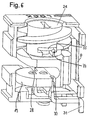
- Fig. 2-4
- verschiedene perspektivische Ansichten eines weiteren Ausführungsbeispiels der Erfindung;
- Fig. 5-7
- weitere perspektivische Ansichten des Ausführungsbeispiels aus Fig. 2-4 in teilweise aufgebrochener Darstellung;
- Fig. 8
- eine Seitenansicht des Ausführungsbeispiels aus Fig. 7;
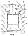
- Fig. 9
- eine Schnittansicht des Ausführungsbeispiels aus Fig. 2 - 8; und
- Fig. 10
- eine Schnittansicht des Ausführungsbeispiels aus Fig. 2 - 8 mit einem eingelegten Zweileiter-Kabel im ASI-Standard und
- Fig. 11
- eine Seitenansicht eines dritten Ausführungsbeispiels der Erfindung.
- Fig. 1a
- a perspective view of a first embodiment of a first connection device on a cable in a blasting view;
- Fig. 1b
- the connection device of Figure 1a on a cable with a closed lid part.
- Fig. 1c
- an explosive view of the connection device of Figure 1a and b on a cable with open lid part.
- Fig. 2-4
- various perspective views of another embodiment of the invention;
- Fig. 5-7
- further perspective views of the embodiment of Figure 2-4 in a partially broken view.
- Fig. 8
- a side view of the embodiment of FIG. 7;
- Fig. 9
- a sectional view of the embodiment of Figures 2-8. and
- Fig. 10
- a sectional view of the embodiment of FIGS. 2-8 with an inserted two-wire cable in the ASI standard and
- Fig. 11
- a side view of a third embodiment of the invention.
Fig. 1a zeigt eine Darstellung eines Abschnittes eines bei allen dargestellten Ausführungen beschaltbaren durchgehenden Flachkabels 1 mit zwei parallel zueinander angeordneten Leitern 2, 3, die in einen umgebenden Mantel 4 aus Isolierstoff eingebettet sind. Der Isolierstoffmantel 4 ist konturiert ausgebildet und weist einerseits obere und untere Kerben 5, 6 zwischen den Leitern 2, 3 auf und andererseits einen Steg 7 zur Polarisierung bzw. optischen Unterscheidung der zwei Leiter 2, 3.1a shows an illustration of a section of a continuous
Zur Realisierung einer T-Stückartigen Abzweigung bzw. zur Realisierung eines elektrischen Anschlusses an das Kabel 1 ohne ein Durchtrennen des Kabels und ohne ein Entfernen des Kabelmantels dienen die in Fig. 1 bis 12 dargestellten Anschlussvorrichtungen 8, die kostengünstig ausgebildet sind und den Abdichtungsstandard "IP 20" erfüllen.To realize a tee-like branch or for the realization of an electrical connection to the
Die Anschlussvorrichtungen 8 weisen jeweils ein Grundgehäuse 9 aus Isolierstoff auf sowie eine mehrteilige Betätigungseinrichtung 10, die dazu dient, das Flachkabel 1 bzw. die zwei Leiter 2, 3 in isolationsdurchdringende Kontakte 11, 12 ― hier gabelförmig mit Kontaktschneiden - im Grundgehäuse 9 einzudrücken. Die isolationsdurchdringenden Kontakte können auch als isolationsdurchstechende Kontakte ― auch Piercingkontakte genannt ― ausgebildet sein, was bei mehradrigen Leiter besonders vorteilhaft ist (Fig. 2 bis 12).The connecting
Die isolationsdurchdringenden Kontakte 11,12 der Fig. 1 sind jeweils in einem mündungsartigen Bereich 13 mit Schneiden zur Isolationsdurchdringung versehen und weisen einen Kontaktschlitz 14 zum Kontaktieren der Leiter auf. Die zwei IDC-Kontakte 11,12 sind ähnlich ausgebildet und im Grundgehäuse 9 in Leiterrichtung axial und radial zueinander versetzt angeordnet. Sie sind ferner hier in vorteilhafter und kostengünstiger Weise einstückig über Stromschienenabschnitte 15 mit Kontakttulpen 16 verbunden, die zum Anschluss externer (hier nicht dargestellter) Leiter in einen nach außen offenen Kragen 17 des Gehäuses 8 ragen, der mit einem korrespondierenden Buchsenteil mit Kontaktstiften (hier nicht dargestellt) zusammensteckbar ist.The
Die Betätigungseinrichtung 10 ist relativ zum Grundgehäuse 9 beweglich und zumindest in einer Offenstellung und in einer Geschlossenstellung nach dem Einlegen des Kabels 1 positionierbar, was die Handhabung vereinfacht. Das Kabel kann dabei am Grundgehäuse 9 oder an der Betätigungseinrichtung 10 vorzugsweise auch vorverrastet werden.The
Das Grundgehäuse 9 der Fig. 1 ist hülsenartig, hier zylindrisch, ausgebildet und mit einem seitlichen Schlitz 18 versehen, in den das Flachkabel einschiebbar ist.The
Die Betätigungseinrichtung 10 weist einen zylindrischen Basiskörper 19 nach Art eines Schiebeelementes auf, der seitlich ebenfalls mit einem Schlitz 20 versehen ist und der teleskopartig in einer axialen Öffnung oder Bohrung 21 des Grundgehäuses 9 verschieblich geführt ist.The
Zum Kontaktieren ist das Flachkabel 1 von der Seite her radial in den Schlitz 18 des Grundgehäuses 9 und in den hiermit fluchtenden Schlitz 20 der Betätigungseinrichtung einzuführen und dann der Basiskörper 19 axial in der Bohrung zu verschieben, bis die Kontaktierung erfolgt.To contact the
Das Verschieben des Basiskörpers 19 in der Öffnung 21 wird mittels eines Schraubelementes realisiert, das mit einem Gewinde am oder im Grundgehäuse 9 zusammenwirkt.The displacement of the
Das Schraubelement ist hier als Deckel 22 realisiert, der nach Art einer Schraubkappe ausgestaltet ist, die ein Innengewinde aufweist und mit einem korrespondierenden Außengewinde 23 des Grundgehäuses 9 zusammenwirkt. Beim Zuschrauben wird der zylindrische Betätigungskörper 19 in der Bohrung 21 verschoben, bis das eingelegte und zuvor vorzugsweise in einer Rastkontur im Schlitz 20 vorverrastete Kabel von den IDC-Kontakten durchdrungen und der Kontakt hergestellt wird. Der Schlitz 18 im Grundgehäuse ist axial so lang, dass ein genügendes axiales Verschieben des Flachkabels 1 im Schlitz möglich ist, um das Flachkabel zu kontaktieren. Denkbar ist auch eine Vorverrastung durch Rasthaken.The screw is realized here as a
Die Fig. 2 - 11 zeigen Ausführungsbeispiele, bei denen das aus Montagegründen vorzugsweise zweistückige Grundgehäuse 9 mit zwei miteinander verrastbaren Gehäusehälften rechtwinklig zueinander ausgerichtete Außenflächen aufweist. Andere Formen sind ebenfalls denkbar. Die dargestellte Ausgestaltung ist aber besonders kompakt und montagefreundlich.FIGS. 2 to 11 show exemplary embodiments in which the
Das Grundgehäuse 9 der Fig.2, das wiederum aus isolierendem Kunststoff besteht, weist wie das Ausführungsbeispiel der Fig. 1 den seitlichen Schlitz 18 auf, in den das Flachkabel 1 einschiebbar ist.The
Die Betätigungseinrichtung 10 weist wiederum einen schlittenartigen Basis- und Betätigungskörper 19 auf, der seitlich ebenfalls mit dem Schlitz 20 versehen ist und der teleskopartig in der Bohrung 21 des Grundgehäuses 9 senkrecht zum zu kontaktierenden Flachkabel verschieblich geführt ist.The
Zum Kontaktieren ist das Flachkabel 1 von der Seite her radial in den Schlitz 18 des Grundgehäuses und in den hiermit fluchtenden Schlitz 20 der Betätigungseinrichtung einzuführen und dann der Basiskörper 19 axial in der Bohrung zu verschieben, bis die Kontaktierung erfolgt.To contact the
Das Verschieben des Basis- bzw. Betätigungskörpers 19 in der Öffnung 21 wird hier nicht wie in Fig. 1 mit einem Deckel sondern mit Hilfe einer Schraube 24 als Schraubelement ― siehe auch Fig. 9 - realisiert, die ein Außengewinde 25 aufweist und mit einem korrespondierenden Innengewinde 26 in einem ersten axialen Bereich der Bohrung 21 des Grundgehäuses 9 zusammenwirkt.The displacement of the base or operating
Beim Beschalten bzw. Einschrauben der madenartig bzw. bolzenartig ohne Schraubenkopf ausgebildeten Schraube 24 drückt diese auf den in axialer Verlängerung der Schraube 24 angeordneten schlittenartigen Betätigungskörper 19 und verschiebt diesen in der Bohrung 21, bis das Kabel von den isolationsdurchdringenden Kontakten 25 durchdrungen und der Kontakt hergestellt wird.When wiring or screwing the maggot-like or bolt-like without screw head formed
Der Schlitz 18 im Grundgehäuse 9 weist eine größere axiale Erstreckung senkrecht zur Erstreckung des Flachkabels aufweist als der Schlitz 20 im Basiskörper 19, um eine genügende Verschiebbarkeit des Kabels zu realisieren.The
Die Kontakte sind hier als isolationsdurchdringende Piercingkontakte 30 ausgestaltet, an die sich jeweils ein Leiterstift 31 anschließt, die jeweils aus dem Grundgehäuse 9 vorstehen und an denen das Grundgehäuse 9 auf einer Leiterplatte montierbar ist (hier nicht dargestellt). Die Leiterstifte können je nach Ausgestaltung gerade oder winklig ausgebildet sein (Fig. 1, Fig. 11), was es erlaubt, Ausgestaltungen verschiedener Art zu realisieren, um die Anschlußvorrichtung auf der Leiterplatte entweder seitlich oder senkrecht nach oben auszurichten.The contacts are configured here as insulation piercing piercing
Die Piercingkontakte durchsetzen Löcher oder Schlitze 32 im Basiskörper und sind im Grundgehäuse fixiert, so dass der Basiskörper auf den Piercingkontakten verschieblich ist.The piercing contacts pass through holes or
Das Grundgehäuse 9 mit relativ großen ebenen ― hier zueinander rechtwinkligen - Außenflächen eignet sich hervorragend zur Nutzung von Bestückungswerkzeugen beispielsweise in Pick-and-Place-Techniken.The
An der Oberfläche des Grundgehäuses 9 ist eine genügend große Fläche für Farbkodierungen oder dgl. vorhanden.On the surface of the
Ein Zeigerelement 27 an der von außen erkenntlichen Schraube 24 erlaubt ― ggf. in Kombination mit einer Gehäusemarkierung oder Beschriftung - eine leichte Erkennbarkeit des Schaltzustandes von Außen. Hier schließt sich das Zeigerelement 27 seitlich an einen Betätigungsschlitz 28 zum Ansetzen eines Werkzeugs, insbesondere eines Schraubendrehers an.A
Vorzugsweise ist das Gewinde 25, 26 des Schraubelementes selbsthemmend ausgelegt, was sowohl die Offenstellung als auch die beschaltete Position sichert und insbesondere in Einbausituationen vorteilhaft ist, in denen die gesamte Vorrichtung Vibrationen ausgesetzt ist.Preferably, the
Die Schraube 24 als das auf den Basiskörper bzw. das Schieberelement einwirkende Glied erlaubt die Abstützung der beim Be- und Entschalten auftretenden hohen Kräfte direkt im Gehäuse.The
Der Deckel 22 der Fig. 1 als Schraubelement kann vorzugsweise manuell betätigt werden. Bei der Schraube 24 wird eine Schraubendreherbetätigung bevorzugt, die einfach, schnell und sicher durchführbar ist. Bevorzugt ist das Gewinde so ausgelegt, dass mit einer weniger als einer ganzen Umdrehung, insbesondere einer halben Umdrehung um 180°, eine Be- oder Entschaltung des Kontaktes schnell und einfach möglich ist.The
Rastkonturen 28 (Fig. 10) im Schlitz 18 des Betätigungselementes ermöglichen eine sichere Vorverrastung des zu kontaktierenden durchgehenden Kabels.Lock contours 28 (Fig. 10) in the
Im Grundgehäuse können seitlich des Schlitzes des Betätigungselementes Vorsprünge 29 oder dgl. ausgebildet sein, die zur Realisierung einer Zugentlastung und zur Litzenabstützung dienen.In the base housing may laterally of the slot of the
Damit das Schraubelement das Basiselement 19 und damit den Leiter 1 wieder vom Kontakt 30 lösen kann, ist es vorteilhaft, wenn das Schraubelement und das Basiselement 19 formschlüssig ineinander greifen. Dies kann beispielsweise ― wie in Fig. 7 oder 10 zu erkennen - durch eine nut-/federartige Verbindung zwischen der bolzenartigen Schraube (ohne Spitze) 24 und dem Basiselement 19 erfolgen.So that the screw element can release the
Realisierbar ist dies auf einfache Weise beispielsweise mit einem T-förmigen Ansatz 33 am Basiselement 19 erreicht werden, der in eine korrespondierende Nut am Basiselement eingreift. Derart zieht die Schraube 24 beim Lösen das Basiselement 19 und damit auch den Leiter 1 wieder vom Kontakt 30 fort und löst den Leiter 1 nach Art einer Schnellentriegelung aus der Kontaktstellung.This can be achieved in a simple manner, for example with a T-shaped
- Flachkabelflat cable
- 11
- Leiterladder
- 2, 32, 3
- Mantelcoat
- 44
- Kerbennotch
- 5, 65, 6
- Stegweb
- 77
- Anschlussvorrichtungenconnecting devices
- 88th
- GrundgehäuseHeaders
- 99
- Betätigungseinrichtungactuator
- 1010
- Kontaktecontacts
- 11, 1211, 12
- mündungsartiger Bereichmuzzle-like area
- 1313
- Kontaktschlitzcontact slot
- 1414
- StromschienenabschnitteBusbar sections
- 1515
- KontakttulpenContact tulips
- 1616
- Kragencollar
- 1717
- Schlitzslot
- 1818
- Basiskörperbase body
- 1919
- Schlitzslot
- 2020
- Bohrungdrilling
- 2121
- Deckelcover
- 2222
- Außengewindeexternal thread
- 2323
- Schraubescrew
- 2424
- IDC-KontakteIDC contacts
- 2525
- Leiterstiftconductor pin
- 2626
- Zeigerelementpointer element
- 2727
- Rastkonturcatch contour
- 2828
- Vorsprüngeprojections
- 2929
- Außengewindeexternal thread
- 3030
- Innengewindeinner thread
- 3131
- Schlitzeslots
- 3232
- Ansatzapproach
- 3333
- Nutgroove
- 3434
Claims (20)
dadurch gekennzeichnet, dass
characterized in that
Applications Claiming Priority (2)
| Application Number | Priority Date | Filing Date | Title |
|---|---|---|---|
| DE202005009442 | 2005-06-16 | ||
| DE202006000967U DE202006000967U1 (en) | 2005-06-16 | 2006-01-20 | Connection device for cables |
Publications (3)
| Publication Number | Publication Date |
|---|---|
| EP1734612A2 true EP1734612A2 (en) | 2006-12-20 |
| EP1734612A3 EP1734612A3 (en) | 2010-02-10 |
| EP1734612B1 EP1734612B1 (en) | 2011-04-27 |
Family
ID=36997584
Family Applications (1)
| Application Number | Title | Priority Date | Filing Date |
|---|---|---|---|
| EP06115502A Not-in-force EP1734612B1 (en) | 2005-06-16 | 2006-06-14 | Device for connecting cables |
Country Status (3)
| Country | Link |
|---|---|
| EP (1) | EP1734612B1 (en) |
| AT (1) | ATE507594T1 (en) |
| DE (2) | DE202006000967U1 (en) |
Family Cites Families (7)
| Publication number | Priority date | Publication date | Assignee | Title |
|---|---|---|---|---|
| US4403821A (en) * | 1979-03-05 | 1983-09-13 | Amp Incorporated | Wiring line tap |
| DE3545305C2 (en) * | 1985-12-20 | 1994-04-14 | Metz Albert Ria Electronic | Clamp for connecting a ribbon cable with several insulated conductors |
| US5149278A (en) * | 1991-02-22 | 1992-09-22 | Psi Telecommunications, Inc. | Terminal block |
| EP0854538A3 (en) * | 1997-01-20 | 1999-09-08 | Fornitalia S.r.l. | Grub screw for a connecting terminal of an electrical cable, adapted to pierce through the insulating sheath and establish the contact |
| US5928026A (en) * | 1997-10-09 | 1999-07-27 | Bright Yin Huey Co., Ltd | Floor lamp plug device |
| AU3284400A (en) * | 1999-03-12 | 2000-10-04 | Grote & Hartmann Gmbh & Co. Kg | Electrical plug-in connector with at least one insulation displacement contact element consisting of a sheet metal stamping, and corresponding mating connector |
| EP1313172A1 (en) * | 2001-11-16 | 2003-05-21 | ERICH JAEGER GmbH & Co. KG | Cable connector |
-
2006
- 2006-01-20 DE DE202006000967U patent/DE202006000967U1/en not_active Expired - Lifetime
- 2006-06-14 AT AT06115502T patent/ATE507594T1/en active
- 2006-06-14 EP EP06115502A patent/EP1734612B1/en not_active Not-in-force
- 2006-06-14 DE DE502006009379T patent/DE502006009379D1/en active Active
Non-Patent Citations (1)
| Title |
|---|
| None |
Also Published As
| Publication number | Publication date |
|---|---|
| EP1734612B1 (en) | 2011-04-27 |
| ATE507594T1 (en) | 2011-05-15 |
| DE202006000967U1 (en) | 2006-10-26 |
| DE502006009379D1 (en) | 2011-06-09 |
| EP1734612A3 (en) | 2010-02-10 |
Similar Documents
| Publication | Publication Date | Title |
|---|---|---|
| EP0726623B1 (en) | Connecting device for free connection of a reusable electrical connector or tapping on electrical multiple-wire lines | |
| EP2301115B1 (en) | Electrical connection device | |
| EP1983616B1 (en) | Bus connector for a ribbon cable and corresponding method for its connection | |
| EP2366212B1 (en) | Electric multiple distributor | |
| WO2013167253A1 (en) | Electrical series terminal | |
| EP2932566B1 (en) | Automobile charging plug | |
| WO2008052845A2 (en) | Plug connector, particularly for sensor-/actuatorlines | |
| DE102013103446A1 (en) | Connector device | |
| DE102005012441B4 (en) | Electrical connector and method of making an electrical connector | |
| EP3021421A1 (en) | Connection device for multi-conductor cables | |
| EP1133813B1 (en) | Device for contacting an electric cable, especially a flat conductor cable | |
| DE3135173C2 (en) | Installation part designed as an electrical plug or as a socket or as a coupling socket | |
| EP3136513A1 (en) | Connection device for connecting a conductor to a busbar | |
| EP1467441A2 (en) | Connector for quick connection in collet attachment technologie | |
| EP1734612B1 (en) | Device for connecting cables | |
| DE10128691B4 (en) | connecting device | |
| DE10323616A1 (en) | Rapid connection plug or socket connector in clamping jaws technology has contact partner with region in form of clamping jaws for accommodating stripped end of line of especially multi-strand cable | |
| DE19513645C2 (en) | Terminal arrangement | |
| EP3750213A1 (en) | Connection module for connecting an electric conductor, and device with an external busbar piece and a connection module | |
| EP1734614A2 (en) | Device for connecting cables | |
| DE19525801A1 (en) | In-line connector for two electrical conductors - has plug-and-socket formed to ensure that ends of cable wires are brought into good contact | |
| EP1286422B1 (en) | Assembly comprising insulation-displacement terminal fittings and crimping ferrules | |
| DE102006017983A1 (en) | Electrical plug-in connection for use in e.g. switch cabinet, has retaining screw, where threaded regions of retainer nut are aligned to non-threaded regions of screw and vice versa, and screw is insertable into nut | |
| WO2024017778A1 (en) | Toollessly configurable plug-in connector with a variable cable outlet direction | |
| EP4203197A1 (en) | Housing for receiving one or more conductor connection terminals and set formed therewith |
Legal Events
| Date | Code | Title | Description |
|---|---|---|---|
| PUAI | Public reference made under article 153(3) epc to a published international application that has entered the european phase |
Free format text: ORIGINAL CODE: 0009012 |
|
| AK | Designated contracting states |
Kind code of ref document: A2 Designated state(s): AT BE BG CH CY CZ DE DK EE ES FI FR GB GR HU IE IS IT LI LT LU LV MC NL PL PT RO SE SI SK TR |
|
| AX | Request for extension of the european patent |
Extension state: AL BA HR MK YU |
|
| PUAL | Search report despatched |
Free format text: ORIGINAL CODE: 0009013 |
|
| AK | Designated contracting states |
Kind code of ref document: A3 Designated state(s): AT BE BG CH CY CZ DE DK EE ES FI FR GB GR HU IE IS IT LI LT LU LV MC NL PL PT RO SE SI SK TR |
|
| AX | Request for extension of the european patent |
Extension state: AL BA HR MK RS |
|
| RIC1 | Information provided on ipc code assigned before grant |
Ipc: H01R 4/30 20060101ALI20100105BHEP Ipc: H01R 4/24 20060101AFI20060927BHEP Ipc: H01R 12/08 20060101ALI20100105BHEP |
|
| 17P | Request for examination filed |
Effective date: 20100615 |
|
| 17Q | First examination report despatched |
Effective date: 20100714 |
|
| AKX | Designation fees paid |
Designated state(s): AT BE BG CH CY CZ DE DK EE ES FI FR GB GR HU IE IS IT LI LT LU LV MC NL PL PT RO SE SI SK TR |
|
| GRAP | Despatch of communication of intention to grant a patent |
Free format text: ORIGINAL CODE: EPIDOSNIGR1 |
|
| RIC1 | Information provided on ipc code assigned before grant |
Ipc: H01R 25/14 20060101ALI20101011BHEP Ipc: H01R 9/05 20060101AFI20101011BHEP |
|
| GRAS | Grant fee paid |
Free format text: ORIGINAL CODE: EPIDOSNIGR3 |
|
| GRAA | (expected) grant |
Free format text: ORIGINAL CODE: 0009210 |
|
| AK | Designated contracting states |
Kind code of ref document: B1 Designated state(s): AT BE BG CH CY CZ DE DK EE ES FI FR GB GR HU IE IS IT LI LT LU LV MC NL PL PT RO SE SI SK TR |
|
| REG | Reference to a national code |
Ref country code: GB Ref legal event code: FG4D Free format text: NOT ENGLISH |
|
| REG | Reference to a national code |
Ref country code: CH Ref legal event code: EP |
|
| REG | Reference to a national code |
Ref country code: IE Ref legal event code: FG4D Free format text: LANGUAGE OF EP DOCUMENT: GERMAN |
|
| REF | Corresponds to: |
Ref document number: 502006009379 Country of ref document: DE Date of ref document: 20110609 Kind code of ref document: P |
|
| REG | Reference to a national code |
Ref country code: DE Ref legal event code: R096 Ref document number: 502006009379 Country of ref document: DE Effective date: 20110609 |
|
| REG | Reference to a national code |
Ref country code: NL Ref legal event code: VDEP Effective date: 20110427 |
|
| LTIE | Lt: invalidation of european patent or patent extension |
Effective date: 20110427 |
|
| PG25 | Lapsed in a contracting state [announced via postgrant information from national office to epo] |
Ref country code: PT Free format text: LAPSE BECAUSE OF FAILURE TO SUBMIT A TRANSLATION OF THE DESCRIPTION OR TO PAY THE FEE WITHIN THE PRESCRIBED TIME-LIMIT Effective date: 20110829 Ref country code: SE Free format text: LAPSE BECAUSE OF FAILURE TO SUBMIT A TRANSLATION OF THE DESCRIPTION OR TO PAY THE FEE WITHIN THE PRESCRIBED TIME-LIMIT Effective date: 20110427 Ref country code: LT Free format text: LAPSE BECAUSE OF FAILURE TO SUBMIT A TRANSLATION OF THE DESCRIPTION OR TO PAY THE FEE WITHIN THE PRESCRIBED TIME-LIMIT Effective date: 20110427 |
|
| REG | Reference to a national code |
Ref country code: IE Ref legal event code: FD4D |
|
| PG25 | Lapsed in a contracting state [announced via postgrant information from national office to epo] |
Ref country code: SI Free format text: LAPSE BECAUSE OF FAILURE TO SUBMIT A TRANSLATION OF THE DESCRIPTION OR TO PAY THE FEE WITHIN THE PRESCRIBED TIME-LIMIT Effective date: 20110427 Ref country code: IS Free format text: LAPSE BECAUSE OF FAILURE TO SUBMIT A TRANSLATION OF THE DESCRIPTION OR TO PAY THE FEE WITHIN THE PRESCRIBED TIME-LIMIT Effective date: 20110827 Ref country code: GR Free format text: LAPSE BECAUSE OF FAILURE TO SUBMIT A TRANSLATION OF THE DESCRIPTION OR TO PAY THE FEE WITHIN THE PRESCRIBED TIME-LIMIT Effective date: 20110728 Ref country code: ES Free format text: LAPSE BECAUSE OF FAILURE TO SUBMIT A TRANSLATION OF THE DESCRIPTION OR TO PAY THE FEE WITHIN THE PRESCRIBED TIME-LIMIT Effective date: 20110807 Ref country code: LV Free format text: LAPSE BECAUSE OF FAILURE TO SUBMIT A TRANSLATION OF THE DESCRIPTION OR TO PAY THE FEE WITHIN THE PRESCRIBED TIME-LIMIT Effective date: 20110427 Ref country code: CY Free format text: LAPSE BECAUSE OF FAILURE TO SUBMIT A TRANSLATION OF THE DESCRIPTION OR TO PAY THE FEE WITHIN THE PRESCRIBED TIME-LIMIT Effective date: 20110427 Ref country code: FI Free format text: LAPSE BECAUSE OF FAILURE TO SUBMIT A TRANSLATION OF THE DESCRIPTION OR TO PAY THE FEE WITHIN THE PRESCRIBED TIME-LIMIT Effective date: 20110427 |
|
| PG25 | Lapsed in a contracting state [announced via postgrant information from national office to epo] |
Ref country code: NL Free format text: LAPSE BECAUSE OF FAILURE TO SUBMIT A TRANSLATION OF THE DESCRIPTION OR TO PAY THE FEE WITHIN THE PRESCRIBED TIME-LIMIT Effective date: 20110427 |
|
| BERE | Be: lapsed |
Owner name: WEIDMULLER INTERFACE G.M.B.H. & CO. KG Effective date: 20110630 |
|
| PG25 | Lapsed in a contracting state [announced via postgrant information from national office to epo] |
Ref country code: EE Free format text: LAPSE BECAUSE OF FAILURE TO SUBMIT A TRANSLATION OF THE DESCRIPTION OR TO PAY THE FEE WITHIN THE PRESCRIBED TIME-LIMIT Effective date: 20110427 Ref country code: IE Free format text: LAPSE BECAUSE OF FAILURE TO SUBMIT A TRANSLATION OF THE DESCRIPTION OR TO PAY THE FEE WITHIN THE PRESCRIBED TIME-LIMIT Effective date: 20110427 Ref country code: CZ Free format text: LAPSE BECAUSE OF FAILURE TO SUBMIT A TRANSLATION OF THE DESCRIPTION OR TO PAY THE FEE WITHIN THE PRESCRIBED TIME-LIMIT Effective date: 20110427 |
|
| REG | Reference to a national code |
Ref country code: CH Ref legal event code: PL |
|
| PG25 | Lapsed in a contracting state [announced via postgrant information from national office to epo] |
Ref country code: SK Free format text: LAPSE BECAUSE OF FAILURE TO SUBMIT A TRANSLATION OF THE DESCRIPTION OR TO PAY THE FEE WITHIN THE PRESCRIBED TIME-LIMIT Effective date: 20110427 Ref country code: PL Free format text: LAPSE BECAUSE OF FAILURE TO SUBMIT A TRANSLATION OF THE DESCRIPTION OR TO PAY THE FEE WITHIN THE PRESCRIBED TIME-LIMIT Effective date: 20110427 Ref country code: RO Free format text: LAPSE BECAUSE OF FAILURE TO SUBMIT A TRANSLATION OF THE DESCRIPTION OR TO PAY THE FEE WITHIN THE PRESCRIBED TIME-LIMIT Effective date: 20110427 Ref country code: DK Free format text: LAPSE BECAUSE OF FAILURE TO SUBMIT A TRANSLATION OF THE DESCRIPTION OR TO PAY THE FEE WITHIN THE PRESCRIBED TIME-LIMIT Effective date: 20110427 |
|
| PLBE | No opposition filed within time limit |
Free format text: ORIGINAL CODE: 0009261 |
|
| STAA | Information on the status of an ep patent application or granted ep patent |
Free format text: STATUS: NO OPPOSITION FILED WITHIN TIME LIMIT |
|
| REG | Reference to a national code |
Ref country code: FR Ref legal event code: ST Effective date: 20120229 |
|
| GBPC | Gb: european patent ceased through non-payment of renewal fee |
Effective date: 20110727 |
|
| PG25 | Lapsed in a contracting state [announced via postgrant information from national office to epo] |
Ref country code: BE Free format text: LAPSE BECAUSE OF NON-PAYMENT OF DUE FEES Effective date: 20110630 |
|
| 26N | No opposition filed |
Effective date: 20120130 |
|
| REG | Reference to a national code |
Ref country code: DE Ref legal event code: R119 Ref document number: 502006009379 Country of ref document: DE Effective date: 20120103 |
|
| PG25 | Lapsed in a contracting state [announced via postgrant information from national office to epo] |
Ref country code: DE Free format text: LAPSE BECAUSE OF NON-PAYMENT OF DUE FEES Effective date: 20120103 Ref country code: CH Free format text: LAPSE BECAUSE OF NON-PAYMENT OF DUE FEES Effective date: 20110630 Ref country code: LI Free format text: LAPSE BECAUSE OF NON-PAYMENT OF DUE FEES Effective date: 20110630 Ref country code: FR Free format text: LAPSE BECAUSE OF NON-PAYMENT OF DUE FEES Effective date: 20110630 |
|
| PG25 | Lapsed in a contracting state [announced via postgrant information from national office to epo] |
Ref country code: IT Free format text: LAPSE BECAUSE OF FAILURE TO SUBMIT A TRANSLATION OF THE DESCRIPTION OR TO PAY THE FEE WITHIN THE PRESCRIBED TIME-LIMIT Effective date: 20110427 |
|
| PG25 | Lapsed in a contracting state [announced via postgrant information from national office to epo] |
Ref country code: GB Free format text: LAPSE BECAUSE OF NON-PAYMENT OF DUE FEES Effective date: 20110727 |
|
| REG | Reference to a national code |
Ref country code: AT Ref legal event code: MM01 Ref document number: 507594 Country of ref document: AT Kind code of ref document: T Effective date: 20110614 |
|
| PG25 | Lapsed in a contracting state [announced via postgrant information from national office to epo] |
Ref country code: AT Free format text: LAPSE BECAUSE OF NON-PAYMENT OF DUE FEES Effective date: 20110614 |
|
| PG25 | Lapsed in a contracting state [announced via postgrant information from national office to epo] |
Ref country code: MC Free format text: LAPSE BECAUSE OF NON-PAYMENT OF DUE FEES Effective date: 20110630 |
|
| PG25 | Lapsed in a contracting state [announced via postgrant information from national office to epo] |
Ref country code: LU Free format text: LAPSE BECAUSE OF NON-PAYMENT OF DUE FEES Effective date: 20110614 |
|
| PG25 | Lapsed in a contracting state [announced via postgrant information from national office to epo] |
Ref country code: BG Free format text: LAPSE BECAUSE OF FAILURE TO SUBMIT A TRANSLATION OF THE DESCRIPTION OR TO PAY THE FEE WITHIN THE PRESCRIBED TIME-LIMIT Effective date: 20110727 |
|
| PG25 | Lapsed in a contracting state [announced via postgrant information from national office to epo] |
Ref country code: TR Free format text: LAPSE BECAUSE OF FAILURE TO SUBMIT A TRANSLATION OF THE DESCRIPTION OR TO PAY THE FEE WITHIN THE PRESCRIBED TIME-LIMIT Effective date: 20110427 |
|
| PG25 | Lapsed in a contracting state [announced via postgrant information from national office to epo] |
Ref country code: HU Free format text: LAPSE BECAUSE OF FAILURE TO SUBMIT A TRANSLATION OF THE DESCRIPTION OR TO PAY THE FEE WITHIN THE PRESCRIBED TIME-LIMIT Effective date: 20110427 |