EP1734574A1 - Method and apparatus for transporting a substrate using non-newtonian fluid - Google Patents
Method and apparatus for transporting a substrate using non-newtonian fluid Download PDFInfo
- Publication number
- EP1734574A1 EP1734574A1 EP06253004A EP06253004A EP1734574A1 EP 1734574 A1 EP1734574 A1 EP 1734574A1 EP 06253004 A EP06253004 A EP 06253004A EP 06253004 A EP06253004 A EP 06253004A EP 1734574 A1 EP1734574 A1 EP 1734574A1
- Authority
- EP
- European Patent Office
- Prior art keywords
- substrate
- newtonian fluid
- chamber
- opening
- flow
- Prior art date
- Legal status (The legal status is an assumption and is not a legal conclusion. Google has not performed a legal analysis and makes no representation as to the accuracy of the status listed.)
- Withdrawn
Links
Images




Classifications
-
- H—ELECTRICITY
- H10—SEMICONDUCTOR DEVICES; ELECTRIC SOLID-STATE DEVICES NOT OTHERWISE PROVIDED FOR
- H10P—GENERIC PROCESSES OR APPARATUS FOR THE MANUFACTURE OR TREATMENT OF DEVICES COVERED BY CLASS H10
- H10P72/00—Handling or holding of wafers, substrates or devices during manufacture or treatment thereof
- H10P72/30—Handling or holding of wafers, substrates or devices during manufacture or treatment thereof for conveying, e.g. between different workstations
- H10P72/36—Handling or holding of wafers, substrates or devices during manufacture or treatment thereof for conveying, e.g. between different workstations using air tracks
-
- B—PERFORMING OPERATIONS; TRANSPORTING
- B65—CONVEYING; PACKING; STORING; HANDLING THIN OR FILAMENTARY MATERIAL
- B65G—TRANSPORT OR STORAGE DEVICES, e.g. CONVEYORS FOR LOADING OR TIPPING, SHOP CONVEYOR SYSTEMS OR PNEUMATIC TUBE CONVEYORS
- B65G49/00—Conveying systems characterised by their application for specified purposes not otherwise provided for
- B65G49/05—Conveying systems characterised by their application for specified purposes not otherwise provided for for fragile or damageable materials or articles
- B65G49/06—Conveying systems characterised by their application for specified purposes not otherwise provided for for fragile or damageable materials or articles for fragile sheets, e.g. glass
- B65G49/063—Transporting devices for sheet glass
- B65G49/064—Transporting devices for sheet glass in a horizontal position
- B65G49/065—Transporting devices for sheet glass in a horizontal position supported partially or completely on fluid cushions, e.g. a gas cushion
-
- B—PERFORMING OPERATIONS; TRANSPORTING
- B65—CONVEYING; PACKING; STORING; HANDLING THIN OR FILAMENTARY MATERIAL
- B65G—TRANSPORT OR STORAGE DEVICES, e.g. CONVEYORS FOR LOADING OR TIPPING, SHOP CONVEYOR SYSTEMS OR PNEUMATIC TUBE CONVEYORS
- B65G54/00—Non-mechanical conveyors not otherwise provided for
-
- H—ELECTRICITY
- H10—SEMICONDUCTOR DEVICES; ELECTRIC SOLID-STATE DEVICES NOT OTHERWISE PROVIDED FOR
- H10P—GENERIC PROCESSES OR APPARATUS FOR THE MANUFACTURE OR TREATMENT OF DEVICES COVERED BY CLASS H10
- H10P72/00—Handling or holding of wafers, substrates or devices during manufacture or treatment thereof
- H10P72/04—Apparatus for manufacture or treatment
- H10P72/0402—Apparatus for fluid treatment
- H10P72/0406—Apparatus for fluid treatment for cleaning followed by drying, rinsing, stripping, blasting or the like
- H10P72/0411—Apparatus for fluid treatment for cleaning followed by drying, rinsing, stripping, blasting or the like for wet cleaning or washing
- H10P72/0416—Apparatus for fluid treatment for cleaning followed by drying, rinsing, stripping, blasting or the like for wet cleaning or washing with the semiconductor substrates being dipped in baths or vessels
Definitions
- a substrate such as a semiconductor wafer
- mechanical rollers are typically used in semiconductor manufacturing systems to move the substrate within the system.
- a substrate may be placed between rollers such that the tapered surfaces of the rollers catch the edges of the substrate.
- the rollers rotate to push the substrate towards a direction of the rotation.
- the problem with rollers, and other mechanical devices, is that the mechanisms associated with the rollers can be complicated.
- rollers must make contact with the substrate to move the substrate. Such contact can exert considerable stress on the substrate, which may lead to the degradation of the substrate.
- Water also has been used to move a substrate.
- the substrate can be placed in a flow of water to move the substrate in a direction of the flow.
- the problem with using water to transport the substrate is that the substrate can sink and stick to a bottom surface, thereby impeding transport of the substrate.
- the substrate cannot easily be dislodged.
- the substrate sinks to the bottom because water cannot support the substrate. Accordingly, the use of water to transport the substrate can be unreliable and the substrate is prone to being stuck at the bottom.
- the present invention fills these needs by providing methods, apparatuses, and systems for transporting a substrate. It should be appreciated that the present invention can be implemented in numerous ways, including as a method, a system, or a device. Several inventive embodiments of the present invention are described below.
- an apparatus in accordance with a first aspect of the present invention, includes a chamber with a cavity in a form of a conduit.
- the conduit is configured to convey a non-Newtonian fluid to enable transport of a substrate through the conduit.
- a system for transporting a substrate includes a chamber that has an input end, an output end, and an input port in a wall of the chamber.
- the input end defines a first opening capable of receiving the substrate and the output end defines a second opening.
- the input port is proximate to the first opening and configured to port a non-Newtonian fluid into the chamber.
- the system additionally includes a non-Newtonian fluid applicator coupled to the input port.
- the non-Newtonian fluid applicator is configured to port the non-Newtonian fluid through the input port into the chamber to enable a flow of the non-Newtonian fluid towards the second opening, whereby the flow is capable of moving the substrate from the first opening to the second opening.
- a method for transporting a substrate is provided.
- a non-Newtonian fluid is provided and the substrate is suspended in the non-Newtonian fluid.
- the substrate can be suspended because the non-Newtonian fluid is capable of supporting the substrate.
- a supply force is applied on the non-Newtonian fluid to cause the non-Newtonian fluid to flow, whereby the flow is capable of moving the substrate along a direction of the flow.
- a method for transporting a substrate is provided.
- a chamber in a form of a conduit is filled with a non-Newtonian fluid.
- the chamber has an input end and an output end.
- the substrate is introduced into the chamber at the input end such that the substrate is suspended in the non-Newtonian fluid. Additional non-Newtonian fluids are forced through the chamber such that a flow of the non-Newtonian fluid moves over surfaces of the substrate and the non-Newtonian fluid exits at the output end.
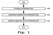
- Figure 1 is a flowchart diagram of a high level overview of a method for transporting a substrate, in accordance with one embodiment of the present invention.
- Figure 2A is a simplified perspective view of an apparatus for transporting a substrate along a horizontal direction, in accordance with one embodiment of the present invention.
- Figure 2B is a sectional, side view of a transport portion of the apparatus shown in Figure 2A.
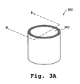
- Figure 3A is a simplified perspective view of an apparatus for transporting a substrate along a vertical direction, in accordance with one embodiment of the present invention.
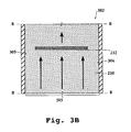
- Figure 3B is a sectional, side view of a transport portion of the apparatus shown in Figure 3A.
- Figures 4A-C are various views of another apparatus for transporting a substrate, in accordance with one embodiment of the present invention.
- FIG. 5 is a block diagram of a semiconductor substrate cleaning system utilizing the apparatus shown in Figure 4 to transport a substrate, in accordance with one embodiment of the present invention.
- an apparatus for transporting the substrate includes a chamber that has a cavity in a form of a conduit.
- the conduit can convey the non-Newtonian fluid to enable transport of the substrate through the conduit.
- FIG. 1 is a flowchart diagram of a high level overview of a method for transporting a substrate, in accordance with one embodiment of the present invention.
- a non-Newtonian fluid is first provided in operation 110.
- the non-Newtonian fluid is a fluid in which the viscosity changes with an applied shear force.
- An example of a non-Newtonian fluid is a soft condensed matter which occupies a middle ground between the extremes of a solid and a liquid.
- the soft condensed matter is easily deformable by external stresses and examples of the soft condensed matter include emulsions, colloids, foam, etc.
- an emulsion is a mixture of immiscible liquids such as, for example, toothpaste, mayonnaise, oil in water, etc.
- a colloid is polymers dispersed in water, and gelatin is an example of a colloid.
- Foam is gas bubbles defined in a liquid matrix, and shaving cream is an example of a foam.
- a substrate is suspended in the non-Newtonian fluid in operation 112.
- the substrate is immersed in the non-Newtonian fluid.
- the non-Newtonian fluid can support the substrate almost indefinitely, even without flow, because the non-Newtonian fluid is characterized by a yield point below which the non-Newtonian fluid does not flow.
- the weight of the substrate is sufficiently small such that the substrate resting on the non-Newtonian fluid does not exceed the yield point of the non-Newtonian fluid. Accordingly, the non-Newtonian fluid can support the substrate.
- a substrate is any suitable base material.
- the substrate is a semiconductor wafer, which is a thin slice of semiconductor material, such as a silicon crystal, upon which microcircuits are constructed by diffusion and deposition of various materials.
- the substrate is a hard disk platter, which is composed of a round, rigid plate with a magnetic media coating.
- a supply force is applied on the non-Newtonian fluid in operation 114 to cause the non-Newtonian fluid to flow.
- the flow of the non-Newtonian fluid exerts a force on the substrate and moves the substrate along a direction of the flow.
- a flow of the non-Newtonian fluid can transport the substrate.
- Figure 2A is a simplified perspective view of an apparatus for transporting a substrate along a horizontal direction, in accordance with one embodiment of the present invention.
- Apparatus 214 includes chamber 216 that has a cavity in a form of a conduit.
- the conduit is configured to convey a non-Newtonian fluid to enable transport of a substrate through the conduit.
- Figure 2A shows that the cavity has a rectangular shape.
- the cavity may be defined by any suitable shape dimensioned to accommodate and transport the substrate.
- the cavity can have a cylindrical shape.
- Figure 2B is a sectional, side view of a transport portion of the apparatus shown in Figure 2A along cutting plane line A-A.
- chamber 216 of apparatus 214 is filled with non-Newtonian fluid 210.
- Substrate 212 is suspended within non-Newtonian fluid 210.
- a transport portion of chamber 216 is defined by a channel conduit dimensioned to transport substrate 212.
- Figure 2B shows a partially enclosed conduit defining the transport portion.
- the partially enclosed conduit is defined by top planar surface 230 and bottom planar surface 232 that is oriented relative to the top planar surface such as to enclose substrate 212 between the top planar surface and the bottom planar surface.
- Height 240 of conduit as defined by a distance between top planar surface 230 and bottom planar surface 232, can have any suitable dimensions greater than a thickness of substrate 212. For example, if thickness of substrate 212 is one millimeter, then height 240 can be four millimeters.
- a supply force is applied on non-Newtonian fluid 210 to cause the non-Newtonian fluid to flow.
- the supply force may be generated by any suitable methods.
- supply force may be generated by pumping additional non-Newtonian fluid 210 into the chamber.
- the flow of non-Newtonian fluid 210 is capable of moving substrate 212 along a direction of the flow.
- Figure 2B shows the direction of flow from left to right and substantially parallel to surfaces of substrate 212.
- the flow of non-Newtonian fluid 210 moves over surfaces of substrate 212 and exerts a force parallel to surfaces of the substrate to move the substrate horizontally from left to right at or close to a velocity of the flow.
- Figure 3A is a simplified perspective view of an apparatus for transporting a substrate along a vertical direction, in accordance with one embodiment of the present invention.
- Apparatus 302 includes chamber 303 that has a cavity in a form of a cylindrical conduit.
- the conduit is configured to convey a non-Newtonian fluid to enable transport of a substrate through the conduit.
- Figure 3B is a sectional, side view of a transport portion of the apparatus shown in Figure 3A along cutting plane line B-B.
- chamber 303 of apparatus 302 is filled with non-Newtonian fluid 210.
- Substrate 212 is suspended within non-Newtonian fluid 210.
- the transport portion of chamber 303 is defined by a channel conduit dimensioned to transport substrate 212 vertically. When viewed from the side, the conduit is defined by left vertical surface 305 and right vertical surface 304.
- Left vertical surface 305 is oriented relative to right vertical surface 304 such as to enclose substrate 212 between the left vertical surface and the right vertical surface.
- substrate 212 is oriented substantially perpendicular to left vertical surface 305 and right vertical surface 304.
- non-Newtonian fluid 210 flows vertically from bottom to top.
- the direction of the flow of non-Newtonian fluid 210 is substantially perpendicular to surfaces of substrate 212. Accordingly, the flow exerts forces that are substantially perpendicular to a bottom surface of substrate 212 to move the substrate vertically upwards.
- Figures 4A-C are various views of another apparatus for transporting a substrate, in accordance with one embodiment of the present invention.
- Figure 4A illustrates a top view
- Figure 4B illustrates a side view
- Figure 4C illustrates an expanded side view of apparatus 310.
- Apparatus 310 includes a chamber, input ports 332, holding pins 312, and panel 330.
- the chamber has a cavity in a form of a rectangular conduit.
- the chamber has input end 316 and output end 317 that is located opposite to the input end.
- Input end 316 is defined by a first opening that is capable of receiving substrate 212.
- Output end 317 is defined by a second opening that is capable of outputting substrate 212.
- panel 330 proximate to the first opening at input end 316 that can be used to seal off the first opening.
- Apparatus 310 also includes input ports 332 coupled to the walls of the chamber. Input ports 332 are configured to port the non-Newtonian fluid into the chamber. As shown in the top view of Figure 4B, in one embodiment, input ports 332 extend along a width of the chamber. However, it should be appreciated that input ports 332 can have any suitable shapes and sizes. A non-Newtonian applicator (not shown) can be coupled to input ports 332 to port non-Newtonian fluid into the chamber through the input ports. In the embodiment of Figure 4B, apparatus 310 includes two input ports 332 located proximately to input end 316. The side view shows that one of the input ports 332 is located at the top of the chamber and the other input port is located at the bottom.
- Input ports 332 are placed opposite to each other in order to create opposing flows of the non-Newtonian fluid from the top and bottom.
- the opposing flows assist in keeping substrate 212 suspended in the middle of the chamber by exerting forces on opposite surfaces of the substrate.
- apparatus 310 can include one input port or more than two input ports.
- input ports 332 are located proximate to input end 316 because the desired direction of flow is from the input end to output end 317. Nonetheless, it should be appreciated that input ports 332 may be placed in any suitable location within the chamber to create different flow characteristics.
- a non-Newtonian fluid applicator ports a non-Newtonian fluid into the chamber through input ports 332 to fill the chamber with the non-Newtonian fluid.
- substrate 212 is introduced into the chamber though the first opening at input end 316.
- Substrate 212 is introduced such that the substrate is suspended in the non-Newtonian fluid.
- substrate 212 is placed in the chamber such that the substrate is not in contact with a surface of the chamber.
- the non-Newtonian fluid has the capability to support substrate 212 such that the substrate is suspended in the middle of the chamber.
- the opposing flows from input ports 332 also assist in keeping substrate 212 suspended in the middle of the chamber by exerting forces on opposite surfaces of the substrate.
- panel 330 which is proximate to the first opening at input end 316, closes to seal off the first opening. Since the non-Newtonian fluid cannot exit though the first opening at input end 316, the non-Newtonian fluid ported from input ports 332 flows from the input end towards output end 317 to exit at the second opening at the output end. The flow of the non-Newtonian fluid moves over surfaces of substrate 212 and exerts forces on the substrate in a direction of the flow. As a result, the flow moves substrate 212 towards output end 317.
- Embodiments of apparatus 310 can include one or more holding pins 312 within the chamber.
- Holding pins 312 are used to receive an edge of substrate 212 to prevent the movement of the substrate.
- holding pins 312 are located proximate to output end 317 to prevent substrate 212 from moving through the second opening at the output end when the non-Newtonian fluid flows though the chamber.
- Holding pins 312 can hold substrate 212 while enabling the non-Newtonian fluid to flow through the conduit.
- holding pins 312 may be configured to release a hold of the substrate to allow the flow of the non-Newtonian fluid to move the substrate along the conduit and out of the second opening at output end 317. For example, in one embodiment, holding pins 312 can be lowered to allow movement of substrate 212.
- FIG. 5 is a block diagram of a semiconductor substrate cleaning system utilizing the apparatus shown in Figure 4A-C to transport a substrate, in accordance with one embodiment of the present invention.
- Substrate cleaning system 502 is used in a semiconductor device manufacturing process to remove particles and trace metal contamination from a substrate.
- substrate cleaning system 502 includes input station 504, cleaning station A 510, cleaning station B 511, drying station 506, non-Newtonian fluid applicator 512, and output station 508.
- Embodiments of substrate cleaning system 502 can incorporate the apparatus shown in Figure 4A-C in cleaning station A 510 and cleaning station B 511 to transport the substrate. It should be appreciated that cleaning station A 510 and cleaning station B 511 can include any suitable cleaning device configured to clean a substrate.
- cleaning station A 510 and cleaning station B 511 can use foam to clean the substrate.
- foam to clean a substrate For more information on the use of foam to clean a substrate, reference may be made to U.S. Patent Application No. 11/153,957, filed on June 15, 2005 and entitled "Method and Apparatus for Cleaning a Substrate Using Non-Newtonian Fluids.”
- Non-Newtonian fluid applicator 512 that is coupled to cleaning station A 510 and cleaning station B 511 provides a non-Newtonian fluid and supply force to port the non-Newtonian fluid into a chamber of cleaning station A 510.
- rollers in input chamber 504 push the substrate into the chamber of the cleaning station A to stop at holding pins located within the chamber.
- a panel of the cleaning station A closes to seal off an opening of the cleaning station.
- cleaning station A 510 then cleans the substrate. After the substrate is cleaned, the holding pins are lowered to allow the substrate to move with the flow of the non-Newtonian fluid out of cleaning station A 510.
- cleaning station A 510 cleans the substrate
- the substrate is rinsed and introduced into cleaning station B 511 for a second cleaning.
- Cleaning station B 511 can use the same cleaning process as cleaning station A 510 or use a different cleaning process.
- the substrate is transported out of the cleaning station B using a flow of the non-Newtonian fluid, and the substrate is rinsed and then dried at drying station 506. Thereafter, rollers pushes the cleaned, dried substrate out to output station 508, where the substrate is outputted from substrate cleaning system 502.
- the above described embodiments provide methods, apparatuses, and systems for transporting a substrate.
- a flow of non-Newtonian fluid is used to move the substrate from one location to another location.
- the non-Newtonian fluid can support the substrate.
- the substrate will not sink and stick to the bottom when placed in the non-Newtonian fluid.
- the non-Newtonian fluid can support the substrate, no mechanical mechanisms make contact with the substrate during transport.
- the non-Newtonian fluid does not exert any notable stress on the substrate.
- the substrate can be transported by the non-Newtonian fluid without significant stress on the substrate.
Landscapes
- Container, Conveyance, Adherence, Positioning, Of Wafer (AREA)
- Cleaning Or Drying Semiconductors (AREA)
Abstract
Description
- A substrate, such as a semiconductor wafer, can be moved from one location to another location by a variety of methods. For example, mechanical rollers are typically used in semiconductor manufacturing systems to move the substrate within the system. Specifically, a substrate may be placed between rollers such that the tapered surfaces of the rollers catch the edges of the substrate. To move the substrate, the rollers rotate to push the substrate towards a direction of the rotation. The problem with rollers, and other mechanical devices, is that the mechanisms associated with the rollers can be complicated. Furthermore, rollers must make contact with the substrate to move the substrate. Such contact can exert considerable stress on the substrate, which may lead to the degradation of the substrate.
- Water also has been used to move a substrate. For example, the substrate can be placed in a flow of water to move the substrate in a direction of the flow. The problem with using water to transport the substrate is that the substrate can sink and stick to a bottom surface, thereby impeding transport of the substrate. When the substrate is stuck to a surface, the substrate cannot easily be dislodged. The substrate sinks to the bottom because water cannot support the substrate. Accordingly, the use of water to transport the substrate can be unreliable and the substrate is prone to being stuck at the bottom.
- In view of the foregoing, there is a need to provide a simpler and more reliable method and apparatus to transport the substrate.
- Broadly speaking, the present invention fills these needs by providing methods, apparatuses, and systems for transporting a substrate. It should be appreciated that the present invention can be implemented in numerous ways, including as a method, a system, or a device. Several inventive embodiments of the present invention are described below.
- In accordance with a first aspect of the present invention, an apparatus is provided that includes a chamber with a cavity in a form of a conduit. The conduit is configured to convey a non-Newtonian fluid to enable transport of a substrate through the conduit.
- In accordance with a second aspect of the present invention, a system for transporting a substrate is provided. The system includes a chamber that has an input end, an output end, and an input port in a wall of the chamber. The input end defines a first opening capable of receiving the substrate and the output end defines a second opening. The input port is proximate to the first opening and configured to port a non-Newtonian fluid into the chamber. The system additionally includes a non-Newtonian fluid applicator coupled to the input port. The non-Newtonian fluid applicator is configured to port the non-Newtonian fluid through the input port into the chamber to enable a flow of the non-Newtonian fluid towards the second opening, whereby the flow is capable of moving the substrate from the first opening to the second opening.
- In accordance with a third aspect of the present invention, a method for transporting a substrate is provided. In this method, a non-Newtonian fluid is provided and the substrate is suspended in the non-Newtonian fluid. The substrate can be suspended because the non-Newtonian fluid is capable of supporting the substrate. Thereafter, a supply force is applied on the non-Newtonian fluid to cause the non-Newtonian fluid to flow, whereby the flow is capable of moving the substrate along a direction of the flow.
- In accordance with a fourth aspect of the present invention, a method for transporting a substrate is provided. In this method, a chamber in a form of a conduit is filled with a non-Newtonian fluid. The chamber has an input end and an output end. The substrate is introduced into the chamber at the input end such that the substrate is suspended in the non-Newtonian fluid. Additional non-Newtonian fluids are forced through the chamber such that a flow of the non-Newtonian fluid moves over surfaces of the substrate and the non-Newtonian fluid exits at the output end.
- Other aspects and advantages of the invention will become apparent from the following detailed description, taken in conjunction with the accompanying drawings, illustrating by way of example the principles of the invention.
- The present invention will be readily understood by the following detailed description in conjunction with the accompanying drawings, and like reference numerals designate like structural elements.
- Figure 1 is a flowchart diagram of a high level overview of a method for transporting a substrate, in accordance with one embodiment of the present invention.
- Figure 2A is a simplified perspective view of an apparatus for transporting a substrate along a horizontal direction, in accordance with one embodiment of the present invention.
- Figure 2B is a sectional, side view of a transport portion of the apparatus shown in Figure 2A.
- Figure 3A is a simplified perspective view of an apparatus for transporting a substrate along a vertical direction, in accordance with one embodiment of the present invention.
- Figure 3B is a sectional, side view of a transport portion of the apparatus shown in Figure 3A.
- Figures 4A-C are various views of another apparatus for transporting a substrate, in accordance with one embodiment of the present invention.
- Figure 5 is a block diagram of a semiconductor substrate cleaning system utilizing the apparatus shown in Figure 4 to transport a substrate, in accordance with one embodiment of the present invention.
- An invention is described for methods, apparatuses, and systems for transporting a substrate. It will be obvious, however, to one skilled in the art, that the present invention may be practiced without some or all of these specific details. In other instances, well known process operations have not been described in detail in order not to unnecessarily obscure the present invention.
- The embodiments described herein provide methods, apparatuses, and systems for transporting a substrate using a non-Newtonian fluid. Essentially, the substrate is transported by placing the substrate in a flow of the non-Newtonian fluid. The flow of the non-Newtonian fluid moves the substrate along a direction of the flow. As will be explained in more detail below, in one embodiment, an apparatus for transporting the substrate includes a chamber that has a cavity in a form of a conduit. The conduit can convey the non-Newtonian fluid to enable transport of the substrate through the conduit.
- Figure 1 is a flowchart diagram of a high level overview of a method for transporting a substrate, in accordance with one embodiment of the present invention. As shown in Figure 1, a non-Newtonian fluid is first provided in
operation 110. The non-Newtonian fluid is a fluid in which the viscosity changes with an applied shear force. An example of a non-Newtonian fluid is a soft condensed matter which occupies a middle ground between the extremes of a solid and a liquid. The soft condensed matter is easily deformable by external stresses and examples of the soft condensed matter include emulsions, colloids, foam, etc. It should be appreciated that an emulsion is a mixture of immiscible liquids such as, for example, toothpaste, mayonnaise, oil in water, etc. A colloid is polymers dispersed in water, and gelatin is an example of a colloid. Foam is gas bubbles defined in a liquid matrix, and shaving cream is an example of a foam. - After the non-Newtonian fluid is provided, a substrate is suspended in the non-Newtonian fluid in
operation 112. In other words, the substrate is immersed in the non-Newtonian fluid. The non-Newtonian fluid can support the substrate almost indefinitely, even without flow, because the non-Newtonian fluid is characterized by a yield point below which the non-Newtonian fluid does not flow. The weight of the substrate is sufficiently small such that the substrate resting on the non-Newtonian fluid does not exceed the yield point of the non-Newtonian fluid. Accordingly, the non-Newtonian fluid can support the substrate. - A substrate is any suitable base material. In one exemplary embodiment, the substrate is a semiconductor wafer, which is a thin slice of semiconductor material, such as a silicon crystal, upon which microcircuits are constructed by diffusion and deposition of various materials. In another exemplary embodiment, the substrate is a hard disk platter, which is composed of a round, rigid plate with a magnetic media coating.
- Still referring to Figure 1, after the substrate is suspended in the non-Newtonian fluid, a supply force is applied on the non-Newtonian fluid in
operation 114 to cause the non-Newtonian fluid to flow. As will be explained in more detail below, since the substrate is suspended in the non-Newtonian fluid, the flow of the non-Newtonian fluid exerts a force on the substrate and moves the substrate along a direction of the flow. As a result, a flow of the non-Newtonian fluid can transport the substrate. - Figure 2A is a simplified perspective view of an apparatus for transporting a substrate along a horizontal direction, in accordance with one embodiment of the present invention.
Apparatus 214 includeschamber 216 that has a cavity in a form of a conduit. As will be explained in more detail below, the conduit is configured to convey a non-Newtonian fluid to enable transport of a substrate through the conduit. Figure 2A shows that the cavity has a rectangular shape. However, it should be appreciated that the cavity may be defined by any suitable shape dimensioned to accommodate and transport the substrate. For example, in another embodiment, the cavity can have a cylindrical shape. - Figure 2B is a sectional, side view of a transport portion of the apparatus shown in Figure 2A along cutting plane line A-A. As shown in Figure 2B,
chamber 216 ofapparatus 214 is filled withnon-Newtonian fluid 210.Substrate 212 is suspended withinnon-Newtonian fluid 210. A transport portion ofchamber 216 is defined by a channel conduit dimensioned to transportsubstrate 212. For example, Figure 2B shows a partially enclosed conduit defining the transport portion. In particular, when viewed from the side, the partially enclosed conduit is defined by topplanar surface 230 and bottomplanar surface 232 that is oriented relative to the top planar surface such as to enclosesubstrate 212 between the top planar surface and the bottom planar surface.Height 240 of conduit, as defined by a distance between topplanar surface 230 and bottomplanar surface 232, can have any suitable dimensions greater than a thickness ofsubstrate 212. For example, if thickness ofsubstrate 212 is one millimeter, thenheight 240 can be four millimeters. - To transport
substrate 212, a supply force is applied onnon-Newtonian fluid 210 to cause the non-Newtonian fluid to flow. The supply force may be generated by any suitable methods. For example, supply force may be generated by pumping additionalnon-Newtonian fluid 210 into the chamber. The flow ofnon-Newtonian fluid 210 is capable of movingsubstrate 212 along a direction of the flow. Figure 2B shows the direction of flow from left to right and substantially parallel to surfaces ofsubstrate 212. The flow ofnon-Newtonian fluid 210 moves over surfaces ofsubstrate 212 and exerts a force parallel to surfaces of the substrate to move the substrate horizontally from left to right at or close to a velocity of the flow. - Figure 3A is a simplified perspective view of an apparatus for transporting a substrate along a vertical direction, in accordance with one embodiment of the present invention.
Apparatus 302 includeschamber 303 that has a cavity in a form of a cylindrical conduit. The conduit is configured to convey a non-Newtonian fluid to enable transport of a substrate through the conduit. - Figure 3B is a sectional, side view of a transport portion of the apparatus shown in Figure 3A along cutting plane line B-B. As shown in Figure 3B,
chamber 303 ofapparatus 302 is filled withnon-Newtonian fluid 210.Substrate 212 is suspended withinnon-Newtonian fluid 210. The transport portion ofchamber 303 is defined by a channel conduit dimensioned to transportsubstrate 212 vertically. When viewed from the side, the conduit is defined by leftvertical surface 305 and rightvertical surface 304. Leftvertical surface 305 is oriented relative to rightvertical surface 304 such as to enclosesubstrate 212 between the left vertical surface and the right vertical surface. In this embodiment,substrate 212 is oriented substantially perpendicular to leftvertical surface 305 and rightvertical surface 304. - To transport
substrate 212 vertically, a supply force is applied onnon-Newtonian fluid 210 to cause the non-Newtonian fluid to flow. As show in Figure 3B,non-Newtonian fluid 210 flows vertically from bottom to top. The direction of the flow ofnon-Newtonian fluid 210 is substantially perpendicular to surfaces ofsubstrate 212. Accordingly, the flow exerts forces that are substantially perpendicular to a bottom surface ofsubstrate 212 to move the substrate vertically upwards. - Figures 4A-C are various views of another apparatus for transporting a substrate, in accordance with one embodiment of the present invention. Figure 4A illustrates a top view, Figure 4B illustrates a side view, and Figure 4C illustrates an expanded side view of
apparatus 310.Apparatus 310 includes a chamber,input ports 332, holdingpins 312, andpanel 330. The chamber has a cavity in a form of a rectangular conduit. The chamber hasinput end 316 andoutput end 317 that is located opposite to the input end.Input end 316 is defined by a first opening that is capable of receivingsubstrate 212.Output end 317 is defined by a second opening that is capable of outputtingsubstrate 212. Additionally included ispanel 330 proximate to the first opening atinput end 316 that can be used to seal off the first opening. -
Apparatus 310 also includesinput ports 332 coupled to the walls of the chamber.Input ports 332 are configured to port the non-Newtonian fluid into the chamber. As shown in the top view of Figure 4B, in one embodiment,input ports 332 extend along a width of the chamber. However, it should be appreciated thatinput ports 332 can have any suitable shapes and sizes. A non-Newtonian applicator (not shown) can be coupled to inputports 332 to port non-Newtonian fluid into the chamber through the input ports. In the embodiment of Figure 4B,apparatus 310 includes twoinput ports 332 located proximately to inputend 316. The side view shows that one of theinput ports 332 is located at the top of the chamber and the other input port is located at the bottom.Input ports 332 are placed opposite to each other in order to create opposing flows of the non-Newtonian fluid from the top and bottom. The opposing flows assist in keepingsubstrate 212 suspended in the middle of the chamber by exerting forces on opposite surfaces of the substrate. However, depending on the desired direction of flow,apparatus 310 can include one input port or more than two input ports. Further, as will be described in more detail below,input ports 332 are located proximate to inputend 316 because the desired direction of flow is from the input end tooutput end 317. Nonetheless, it should be appreciated thatinput ports 332 may be placed in any suitable location within the chamber to create different flow characteristics. - Still referring to Figures 4A-C, before
substrate 212 is introduced into the chamber ofapparatus 310, a non-Newtonian fluid applicator ports a non-Newtonian fluid into the chamber throughinput ports 332 to fill the chamber with the non-Newtonian fluid. After the chamber is filled with the non-Newtonian fluid,substrate 212 is introduced into the chamber though the first opening atinput end 316.Substrate 212 is introduced such that the substrate is suspended in the non-Newtonian fluid. In other words,substrate 212 is placed in the chamber such that the substrate is not in contact with a surface of the chamber. The non-Newtonian fluid has the capability to supportsubstrate 212 such that the substrate is suspended in the middle of the chamber. The opposing flows frominput ports 332 also assist in keepingsubstrate 212 suspended in the middle of the chamber by exerting forces on opposite surfaces of the substrate. - After
substrate 212 is introduced into the chamber,panel 330, which is proximate to the first opening atinput end 316, closes to seal off the first opening. Since the non-Newtonian fluid cannot exit though the first opening atinput end 316, the non-Newtonian fluid ported frominput ports 332 flows from the input end towardsoutput end 317 to exit at the second opening at the output end. The flow of the non-Newtonian fluid moves over surfaces ofsubstrate 212 and exerts forces on the substrate in a direction of the flow. As a result, the flow movessubstrate 212 towardsoutput end 317. - Embodiments of
apparatus 310 can include one or more holding pins 312 within the chamber. Holding pins 312 are used to receive an edge ofsubstrate 212 to prevent the movement of the substrate. In the embodiment of Figures 4A and 4B, holdingpins 312 are located proximate to output end 317 to preventsubstrate 212 from moving through the second opening at the output end when the non-Newtonian fluid flows though the chamber. Holding pins 312 can holdsubstrate 212 while enabling the non-Newtonian fluid to flow through the conduit. To allow movement ofsubstrate 212, holdingpins 312 may be configured to release a hold of the substrate to allow the flow of the non-Newtonian fluid to move the substrate along the conduit and out of the second opening atoutput end 317. For example, in one embodiment, holdingpins 312 can be lowered to allow movement ofsubstrate 212. - Figure 5 is a block diagram of a semiconductor substrate cleaning system utilizing the apparatus shown in Figure 4A-C to transport a substrate, in accordance with one embodiment of the present invention.
Substrate cleaning system 502 is used in a semiconductor device manufacturing process to remove particles and trace metal contamination from a substrate. As shown in Figure 5,substrate cleaning system 502 includesinput station 504, cleaningstation A 510, cleaningstation B 511, dryingstation 506,non-Newtonian fluid applicator 512, andoutput station 508. Embodiments ofsubstrate cleaning system 502 can incorporate the apparatus shown in Figure 4A-C in cleaningstation A 510 and cleaningstation B 511 to transport the substrate. It should be appreciated that cleaningstation A 510 and cleaningstation B 511 can include any suitable cleaning device configured to clean a substrate. For example, cleaningstation A 510 and cleaningstation B 511 can use foam to clean the substrate. For more information on the use of foam to clean a substrate, reference may be made toU.S. Patent Application No. 11/153,957, filed on June 15, 2005 - An exemplary operation to clean a substrate would start with a substrate inputted into
input station 504. Non-Newtonianfluid applicator 512 that is coupled to cleaningstation A 510 and cleaningstation B 511 provides a non-Newtonian fluid and supply force to port the non-Newtonian fluid into a chamber of cleaningstation A 510. After the chamber of cleaningstation A 510 is filled with the non-Newtonian fluid, rollers ininput chamber 504 push the substrate into the chamber of the cleaning station A to stop at holding pins located within the chamber. When the substrate is fully inserted in cleaningstation A 510, a panel of the cleaning station A closes to seal off an opening of the cleaning station. Using a suitable cleaning method, cleaningstation A 510 then cleans the substrate. After the substrate is cleaned, the holding pins are lowered to allow the substrate to move with the flow of the non-Newtonian fluid out of cleaningstation A 510. - After cleaning
station A 510 cleans the substrate, the substrate is rinsed and introduced into cleaningstation B 511 for a second cleaning.Cleaning station B 511 can use the same cleaning process as cleaningstation A 510 or use a different cleaning process. After cleaningstation B 511 cleans the substrate, the substrate is transported out of the cleaning station B using a flow of the non-Newtonian fluid, and the substrate is rinsed and then dried at dryingstation 506. Thereafter, rollers pushes the cleaned, dried substrate out tooutput station 508, where the substrate is outputted fromsubstrate cleaning system 502. - In summary, the above described embodiments provide methods, apparatuses, and systems for transporting a substrate. Basically, a flow of non-Newtonian fluid is used to move the substrate from one location to another location. Unlike water, the non-Newtonian fluid can support the substrate. As a result, the substrate will not sink and stick to the bottom when placed in the non-Newtonian fluid. Furthermore, since the non-Newtonian fluid can support the substrate, no mechanical mechanisms make contact with the substrate during transport. The non-Newtonian fluid does not exert any notable stress on the substrate. As a result, unlike the use of rollers, the substrate can be transported by the non-Newtonian fluid without significant stress on the substrate.
- Although a few embodiments of the present invention have been described in detail herein, it should be understood, by those of ordinary skill, that the present invention may be embodied in many other specific forms without departing from the spirit or scope of the invention. Therefore, the present examples and embodiments are to be considered as illustrative and not restrictive, and the invention is not to be limited to the details provided therein, but may be modified and practiced within the scope of the appended claims.
Claims (20)
- An apparatus, comprising:a chamber having a cavity in a form of a conduit, the conduit being configured to convey a non-Newtonian fluid to enable transport of a substrate through the conduit.
- The apparatus of claim 1, further comprising:an input port in a wall of the chamber, the input port being configured to port the non-Newtonian fluid into the chamber.
- The apparatus of claim 1, wherein the chamber has an input end and an output end, the input end defining a first opening capable of receiving the substrate, the output end defining a second opening capable of outputting the substrate.
- The apparatus of claim 3, further comprising:a panel proximate to the first opening configured to seal off the first opening.
- The apparatus of claim 3, further comprising:a holding pin within the chamber that is proximate to the second opening, the holding pin being configured to receive an edge of the substrate to prevent movement of the substrate.
- The apparatus of claim 1, wherein the non-Newtonian fluid is defined as soft condensed matter.
- A system for transporting a substrate, comprising:a chamber having an input end, an output end, and an input port in a wall of the chamber, the input end defining a first opening capable of receiving the substrate, the output end defining a second opening, the input port being proximate to the first opening and configured to port a non-Newtonian fluid into the chamber; anda non-Newtonian fluid applicator coupled to the input port, the non-Newtonian fluid applicator being configured to port the non-Newtonian fluid through the input port into the chamber to enable a flow of the non-Newtonian fluid towards the second opening, the flow being capable of moving the substrate from the first opening to the second opening.
- The system of claim 7, wherein a transport portion of the chamber is defined by a channel conduit dimensioned to transport the substrate.
- The system of claim 7, wherein a transport portion of the chamber is defined by a partially enclosed conduit.
- The system of claim 9, wherein the partially enclosed conduit includes,a first planar surface; anda second planar surface oriented relative to the first planar surface configured to enclose the substrate between the first and second planar surfaces.
- The system of claim 7, further comprising:a holding pin within the chamber that is proximate to the second opening, the holding pin being configured to receive an edge of the substrate to prevent the moving of the substrate through the second opening when the non-Newtonian fluid flows through the chamber.
- The system of claim 11, wherein the holding pin is capable of being lowered to enable the substrate to move through the second opening.
- The system of claim 7, wherein a direction of the flow of the non-Newtonian fluid is substantially perpendicular to a surface of the substrate.
- The system of claim 7, wherein a direction of the flow of the non-Newtonian fluid is substantially parallel to a surface of the substrate.
- The system of claim 7, wherein the non-Newtonian fluid is defined as one or more of a foam, a colloid, and an emulsion.
- A method for transporting a substrate, comprising method operations of:providing a non-Newtonian fluid;suspending the substrate in the non-Newtonian fluid, the non-Newtonian fluid being capable of supporting the substrate; andapplying a supply force on the non-Newtonian fluid to cause the non-Newtonian fluid to flow, the flow being capable of moving the substrate along a direction of the flow.
- The method of claim 16, wherein the method operation of suspending the substrate in the non-Newtonian fluid includes,immersing the substrate in the non-Newtonian fluid.
- A method for transporting a substrate, comprising method operations of:filling a chamber in a form of a conduit with a non-Newtonian fluid, the chamber having an input end and an output end;introducing the substrate into the chamber at the input end such that the substrate is suspended in the non-Newtonian fluid; andforcing additional non-Newtonian fluids through the chamber such that a flow of the non-Newtonian fluid moves over surfaces of the substrate and the non-Newtonian fluid exits at the output end.
- The method of claim 18, wherein the substrate is held within the chamber while enabling the non-Newtonian fluid to flow through the chamber.
- The method of claim 19, further comprising:releasing the hold of the substrate to enable the flow of the non-Newtonian fluid to move the substrate along the chamber and out of the output end.
Applications Claiming Priority (1)
| Application Number | Priority Date | Filing Date | Title |
|---|---|---|---|
| US11/154,129 US7416370B2 (en) | 2005-06-15 | 2005-06-15 | Method and apparatus for transporting a substrate using non-Newtonian fluid |
Publications (1)
| Publication Number | Publication Date |
|---|---|
| EP1734574A1 true EP1734574A1 (en) | 2006-12-20 |
Family
ID=36710031
Family Applications (1)
| Application Number | Title | Priority Date | Filing Date |
|---|---|---|---|
| EP06253004A Withdrawn EP1734574A1 (en) | 2005-06-15 | 2006-06-10 | Method and apparatus for transporting a substrate using non-newtonian fluid |
Country Status (8)
| Country | Link |
|---|---|
| US (2) | US7416370B2 (en) |
| EP (1) | EP1734574A1 (en) |
| JP (1) | JP5010856B2 (en) |
| KR (2) | KR101111361B1 (en) |
| CN (1) | CN1880200B (en) |
| MY (1) | MY142184A (en) |
| SG (1) | SG128607A1 (en) |
| TW (1) | TWI322128B (en) |
Families Citing this family (23)
| Publication number | Priority date | Publication date | Assignee | Title |
|---|---|---|---|---|
| US20040031167A1 (en) | 2002-06-13 | 2004-02-19 | Stein Nathan D. | Single wafer method and apparatus for drying semiconductor substrates using an inert gas air-knife |
| US7913703B1 (en) | 2003-06-27 | 2011-03-29 | Lam Research Corporation | Method and apparatus for uniformly applying a multi-phase cleaning solution to a substrate |
| US7799141B2 (en) | 2003-06-27 | 2010-09-21 | Lam Research Corporation | Method and system for using a two-phases substrate cleaning compound |
| US8522801B2 (en) | 2003-06-27 | 2013-09-03 | Lam Research Corporation | Method and apparatus for cleaning a semiconductor substrate |
| US8316866B2 (en) | 2003-06-27 | 2012-11-27 | Lam Research Corporation | Method and apparatus for cleaning a semiconductor substrate |
| US7648584B2 (en) | 2003-06-27 | 2010-01-19 | Lam Research Corporation | Method and apparatus for removing contamination from substrate |
| US7737097B2 (en) | 2003-06-27 | 2010-06-15 | Lam Research Corporation | Method for removing contamination from a substrate and for making a cleaning solution |
| US7568490B2 (en) | 2003-12-23 | 2009-08-04 | Lam Research Corporation | Method and apparatus for cleaning semiconductor wafers using compressed and/or pressurized foams, bubbles, and/or liquids |
| US7416370B2 (en) | 2005-06-15 | 2008-08-26 | Lam Research Corporation | Method and apparatus for transporting a substrate using non-Newtonian fluid |
| US8323420B2 (en) | 2005-06-30 | 2012-12-04 | Lam Research Corporation | Method for removing material from semiconductor wafer and apparatus for performing the same |
| US7862662B2 (en) | 2005-12-30 | 2011-01-04 | Lam Research Corporation | Method and material for cleaning a substrate |
| US8522799B2 (en) | 2005-12-30 | 2013-09-03 | Lam Research Corporation | Apparatus and system for cleaning a substrate |
| US8043441B2 (en) | 2005-06-15 | 2011-10-25 | Lam Research Corporation | Method and apparatus for cleaning a substrate using non-Newtonian fluids |
| EP2428557A1 (en) | 2005-12-30 | 2012-03-14 | LAM Research Corporation | Cleaning solution |
| US8480810B2 (en) * | 2005-12-30 | 2013-07-09 | Lam Research Corporation | Method and apparatus for particle removal |
| US7997289B1 (en) * | 2006-10-03 | 2011-08-16 | Xyratex Technology Limited | Methods of and apparatus for cleaning and conveying a substrate |
| US7897213B2 (en) | 2007-02-08 | 2011-03-01 | Lam Research Corporation | Methods for contained chemical surface treatment |
| US8388762B2 (en) * | 2007-05-02 | 2013-03-05 | Lam Research Corporation | Substrate cleaning technique employing multi-phase solution |
| US8211846B2 (en) | 2007-12-14 | 2012-07-03 | Lam Research Group | Materials for particle removal by single-phase and two-phase media |
| US8845812B2 (en) * | 2009-06-12 | 2014-09-30 | Micron Technology, Inc. | Method for contamination removal using magnetic particles |
| US10258986B2 (en) | 2014-11-12 | 2019-04-16 | University Of New Hampshire | Viscoelastic fluid drop production |
| CN116551419B (en) * | 2023-07-07 | 2023-09-19 | 杭州鄂达精密机电科技有限公司 | Full-automatic clamping assembly for punching batch valve seats |
| CN117465893B (en) * | 2023-12-08 | 2026-03-20 | 中煤科工开采研究院有限公司 | Wear-resistant mining scraper conveyor and wear-resistant methods |
Citations (4)
| Publication number | Priority date | Publication date | Assignee | Title |
|---|---|---|---|---|
| US3617095A (en) * | 1967-10-18 | 1971-11-02 | Petrolite Corp | Method of transporting bulk solids |
| DE4038587A1 (en) * | 1990-12-04 | 1992-06-11 | Hamatech Halbleiter Maschinenb | Conveyor system for flat substrates - transports by liq. film flow along surface e.g. for handling at various work-stations |
| JPH11334874A (en) * | 1998-05-25 | 1999-12-07 | Speedfam-Ipec Co Ltd | Transport device |
| WO2001012384A2 (en) * | 1999-08-12 | 2001-02-22 | Speedfam-Ipec Corporation | Apparatus for moving a workpiece |
Family Cites Families (166)
| Publication number | Priority date | Publication date | Assignee | Title |
|---|---|---|---|---|
| NL251243A (en) | 1959-05-04 | |||
| US3212762A (en) | 1960-05-23 | 1965-10-19 | Dow Chemical Co | Foam generator |
| US3436262A (en) | 1964-09-25 | 1969-04-01 | Dow Chemical Co | Cleaning by foam contact,and foam regeneration method |
| US3978176A (en) | 1972-09-05 | 1976-08-31 | Minnesota Mining And Manufacturing Company | Sparger |
| GB1507472A (en) | 1974-05-02 | 1978-04-12 | Bunker Ramo | Foamable coating remover composition |
| US4156619A (en) | 1975-06-11 | 1979-05-29 | Wacker-Chemitronic Gesellschaft Fur Elektronik-Grundstoffe Mbh | Process for cleaning semi-conductor discs |
| JPS5924849B2 (en) | 1976-03-24 | 1984-06-12 | バブコツク日立株式会社 | Treatment method for exhaust gas containing sulfur oxides |
| JPS5647471Y2 (en) | 1976-11-30 | 1981-11-06 | ||
| US4133773A (en) | 1977-07-28 | 1979-01-09 | The Dow Chemical Company | Apparatus for making foamed cleaning solutions and method of operation |
| US4236851A (en) * | 1978-01-05 | 1980-12-02 | Kasper Instruments, Inc. | Disc handling system and method |
| US4238244A (en) | 1978-10-10 | 1980-12-09 | Halliburton Company | Method of removing deposits from surfaces with a gas agitated cleaning liquid |
| JPS605529Y2 (en) | 1979-05-04 | 1985-02-21 | 株式会社タムラ製作所 | coil |
| JPS5684618U (en) | 1979-12-03 | 1981-07-08 | ||
| JPS5684619U (en) | 1979-12-04 | 1981-07-08 | ||
| US4535580A (en) | 1981-07-09 | 1985-08-20 | Donn Incorporated | Screw slot runner system |
| US4838289A (en) | 1982-08-03 | 1989-06-13 | Texas Instruments Incorporated | Apparatus and method for edge cleaning |
| NZ202329A (en) * | 1982-10-29 | 1986-11-12 | Fibre Dynamics Ltd | Transporting slurry within a pulp |
| US4911761A (en) | 1984-05-21 | 1990-03-27 | Cfm Technologies Research Associates | Process and apparatus for drying surfaces |
| US4573830A (en) * | 1984-06-21 | 1986-03-04 | International Business Machines Corporation | Chip decelerator |
| JPS6181324A (en) * | 1984-09-26 | 1986-04-24 | Shinko Electric Co Ltd | Conveyor |
| JPH027316Y2 (en) | 1986-01-20 | 1990-02-21 | ||
| WO1988000081A1 (en) | 1986-07-08 | 1988-01-14 | Kohlensäurewerk Deutschland Gmbh | Process for separating volatile substances |
| NL8601939A (en) | 1986-07-28 | 1988-02-16 | Philips Nv | METHOD FOR REMOVING UNDESIRABLE PARTICLES FROM A SUBSTRATE SURFACE |
| JPS6377510A (en) | 1986-09-20 | 1988-04-07 | Fujitsu Ltd | Circulation filter for foamy mixed acid |
| US4838219A (en) * | 1986-11-13 | 1989-06-13 | Feuling James J | Curved intake duct having improved flow characteristics |
| US4962776A (en) | 1987-03-26 | 1990-10-16 | Regents Of The University Of Minnesota | Process for surface and fluid cleaning |
| US4817652A (en) | 1987-03-26 | 1989-04-04 | Regents Of The University Of Minnesota | System for surface and fluid cleaning |
| US4849027A (en) | 1987-04-16 | 1989-07-18 | Simmons Bobby G | Method for recycling foamed solvents |
| US5105556A (en) | 1987-08-12 | 1992-04-21 | Hitachi, Ltd. | Vapor washing process and apparatus |
| US5048549A (en) | 1988-03-02 | 1991-09-17 | General Dynamics Corp., Air Defense Systems Div. | Apparatus for cleaning and/or fluxing circuit card assemblies |
| US5181985A (en) | 1988-06-01 | 1993-01-26 | Wacker-Chemitronic Gesellschaft Fur Elektronik-Grundstoffe Mbh | Process for the wet-chemical surface treatment of semiconductor wafers |
| US5488521A (en) * | 1988-10-17 | 1996-01-30 | Conner Peripherals, Inc. | Information recording apparatus with a non-newtonian liquid bearing |
| US5068040A (en) * | 1989-04-03 | 1991-11-26 | Hughes Aircraft Company | Dense phase gas photochemical process for substrate treatment |
| JPH02309638A (en) | 1989-05-24 | 1990-12-25 | Fujitsu Ltd | Wafer etching device |
| US5000795A (en) | 1989-06-16 | 1991-03-19 | At&T Bell Laboratories | Semiconductor wafer cleaning method and apparatus |
| JPH076993Y2 (en) | 1989-07-26 | 1995-02-22 | 株式会社工進精工所 | Metal pipe end processing machine |
| US5102777A (en) | 1990-02-01 | 1992-04-07 | Ardrox Inc. | Resist stripping |
| US5271774A (en) | 1990-03-01 | 1993-12-21 | U.S. Philips Corporation | Method for removing in a centrifuge a liquid from a surface of a substrate |
| DE69102311T2 (en) | 1990-03-07 | 1994-09-29 | Hitachi Ltd | Device and method for surface cleaning. |
| US5306350A (en) | 1990-12-21 | 1994-04-26 | Union Carbide Chemicals & Plastics Technology Corporation | Methods for cleaning apparatus using compressed fluids |
| US5261966A (en) | 1991-01-28 | 1993-11-16 | Kabushiki Kaisha Toshiba | Method of cleaning semiconductor wafers using mixer containing a bundle of gas permeable hollow yarns |
| US5175124A (en) | 1991-03-25 | 1992-12-29 | Motorola, Inc. | Process for fabricating a semiconductor device using re-ionized rinse water |
| US5148549A (en) * | 1991-04-23 | 1992-09-22 | Ergodyne Corporation | Back support with side openings and attached apron |
| US5242669A (en) | 1992-07-09 | 1993-09-07 | The S. A. Day Mfg. Co., Inc. | High purity potassium tetrafluoroaluminate and method of making same |
| JPH06177101A (en) | 1992-12-03 | 1994-06-24 | Mitsubishi Materials Corp | Improved silicon wafer cleaning solution |
| US5288332A (en) | 1993-02-05 | 1994-02-22 | Honeywell Inc. | A process for removing corrosive by-products from a circuit assembly |
| US5336371A (en) | 1993-03-18 | 1994-08-09 | At&T Bell Laboratories | Semiconductor wafer cleaning and rinsing techniques using re-ionized water and tank overflow |
| JP2659321B2 (en) * | 1993-04-20 | 1997-09-30 | 川崎製鉄株式会社 | Wafer transfer device |
| US5911837A (en) | 1993-07-16 | 1999-06-15 | Legacy Systems, Inc. | Process for treatment of semiconductor wafers in a fluid |
| US5464480A (en) | 1993-07-16 | 1995-11-07 | Legacy Systems, Inc. | Process and apparatus for the treatment of semiconductor wafers in a fluid |
| US5472502A (en) | 1993-08-30 | 1995-12-05 | Semiconductor Systems, Inc. | Apparatus and method for spin coating wafers and the like |
| CA2170272C (en) * | 1993-08-31 | 2005-04-05 | Andrew G. Hay | Transporting and metering particulate material |
| US5950645A (en) | 1993-10-20 | 1999-09-14 | Verteq, Inc. | Semiconductor wafer cleaning system |
| US5656097A (en) | 1993-10-20 | 1997-08-12 | Verteq, Inc. | Semiconductor wafer cleaning system |
| US5518542A (en) | 1993-11-05 | 1996-05-21 | Tokyo Electron Limited | Double-sided substrate cleaning apparatus |
| US5938504A (en) | 1993-11-16 | 1999-08-17 | Applied Materials, Inc. | Substrate polishing apparatus |
| JPH07147263A (en) * | 1993-11-24 | 1995-06-06 | Ebara Corp | Wafer carrier system |
| US5417768A (en) | 1993-12-14 | 1995-05-23 | Autoclave Engineers, Inc. | Method of cleaning workpiece with solvent and then with liquid carbon dioxide |
| EP0681317B1 (en) | 1994-04-08 | 2001-10-17 | Texas Instruments Incorporated | Method for cleaning semiconductor wafers using liquefied gases |
| US5498293A (en) | 1994-06-23 | 1996-03-12 | Mallinckrodt Baker, Inc. | Cleaning wafer substrates of metal contamination while maintaining wafer smoothness |
| US6081650A (en) | 1994-06-30 | 2000-06-27 | Thomson Licensing S.A. | Transport processor interface and video recorder/playback apparatus in a field structured datastream suitable for conveying television information |
| US5705223A (en) | 1994-07-26 | 1998-01-06 | International Business Machine Corp. | Method and apparatus for coating a semiconductor wafer |
| US5514417A (en) * | 1994-08-04 | 1996-05-07 | Schuller International, Inc. | Method of and apparatus for coating a molded fibrous workpiece |
| US5772784A (en) | 1994-11-14 | 1998-06-30 | Yieldup International | Ultra-low particle semiconductor cleaner |
| JP3504023B2 (en) | 1995-05-26 | 2004-03-08 | 株式会社ルネサステクノロジ | Cleaning device and cleaning method |
| US5660642A (en) | 1995-05-26 | 1997-08-26 | The Regents Of The University Of California | Moving zone Marangoni drying of wet objects using naturally evaporated solvent vapor |
| US5968285A (en) | 1995-06-07 | 1999-10-19 | Gary W. Ferrell | Methods for drying and cleaning of objects using aerosols and inert gases |
| US5964958A (en) | 1995-06-07 | 1999-10-12 | Gary W. Ferrell | Methods for drying and cleaning objects using aerosols |
| US6532976B1 (en) | 1995-07-10 | 2003-03-18 | Lg Semicon Co., Ltd. | Semiconductor wafer cleaning apparatus |
| DE19622015A1 (en) | 1996-05-31 | 1997-12-04 | Siemens Ag | Process for etching destruction zones on a semiconductor substrate edge and etching system |
| TW416987B (en) | 1996-06-05 | 2001-01-01 | Wako Pure Chem Ind Ltd | A composition for cleaning the semiconductor substrate surface |
| JPH1055993A (en) | 1996-08-09 | 1998-02-24 | Hitachi Ltd | Cleaning solution for manufacturing semiconductor device and method for manufacturing semiconductor device using the same |
| WO1998013149A1 (en) | 1996-09-25 | 1998-04-02 | Shuzurifuresher Kaihatsukyodokumiai | Washing means using liquefied gas of high density |
| US5997653A (en) | 1996-10-07 | 1999-12-07 | Tokyo Electron Limited | Method for washing and drying substrates |
| US5858283A (en) | 1996-11-18 | 1999-01-12 | Burris; William Alan | Sparger |
| US6896826B2 (en) | 1997-01-09 | 2005-05-24 | Advanced Technology Materials, Inc. | Aqueous cleaning composition containing copper-specific corrosion inhibitor for cleaning inorganic residues on semiconductor substrate |
| US5900191A (en) | 1997-01-14 | 1999-05-04 | Stable Air, Inc. | Foam producing apparatus and method |
| US7320457B2 (en) * | 1997-02-07 | 2008-01-22 | Sri International | Electroactive polymer devices for controlling fluid flow |
| US5800626A (en) | 1997-02-18 | 1998-09-01 | International Business Machines Corporation | Control of gas content in process liquids for improved megasonic cleaning of semiconductor wafers and microelectronics substrates |
| US6701941B1 (en) | 1997-05-09 | 2004-03-09 | Semitool, Inc. | Method for treating the surface of a workpiece |
| JPH10321572A (en) | 1997-05-15 | 1998-12-04 | Toshiba Corp | Semiconductor wafer double-side cleaning apparatus and semiconductor wafer polishing method |
| JPH1126423A (en) | 1997-07-09 | 1999-01-29 | Sugai:Kk | Processing method of semiconductor wafer and the like and processing apparatus therefor |
| US6152805A (en) | 1997-07-17 | 2000-11-28 | Canon Kabushiki Kaisha | Polishing machine |
| US5932493A (en) | 1997-09-15 | 1999-08-03 | International Business Machines Corporaiton | Method to minimize watermarks on silicon substrates |
| WO1999016109A1 (en) | 1997-09-24 | 1999-04-01 | Interuniversitair Micro-Elektronica Centrum Vereniging Zonder Winstbejag | Method and apparatus for removing a liquid from a surface |
| US6491764B2 (en) | 1997-09-24 | 2002-12-10 | Interuniversitair Microelektronics Centrum (Imec) | Method and apparatus for removing a liquid from a surface of a rotating substrate |
| US5904156A (en) | 1997-09-24 | 1999-05-18 | International Business Machines Corporation | Dry film resist removal in the presence of electroplated C4's |
| EP0905746A1 (en) | 1997-09-24 | 1999-03-31 | Interuniversitair Micro-Elektronica Centrum Vzw | Method of removing a liquid from a surface of a rotating substrate |
| US6398975B1 (en) | 1997-09-24 | 2002-06-04 | Interuniversitair Microelektronica Centrum (Imec) | Method and apparatus for localized liquid treatment of the surface of a substrate |
| JP3039493B2 (en) | 1997-11-28 | 2000-05-08 | 日本電気株式会社 | Substrate cleaning method and cleaning solution |
| US6270584B1 (en) | 1997-12-03 | 2001-08-07 | Gary W. Ferrell | Apparatus for drying and cleaning objects using controlled aerosols and gases |
| JPH11350169A (en) | 1998-06-10 | 1999-12-21 | Chemitoronics Co | Wet etching apparatus and wet etching method |
| US6049996A (en) | 1998-07-10 | 2000-04-18 | Ball Semiconductor, Inc. | Device and fluid separator for processing spherical shaped devices |
| US6161311A (en) * | 1998-07-10 | 2000-12-19 | Asm America, Inc. | System and method for reducing particles in epitaxial reactors |
| US5944581A (en) | 1998-07-13 | 1999-08-31 | Ford Motor Company | CO2 cleaning system and method |
| JP3003684B1 (en) | 1998-09-07 | 2000-01-31 | 日本電気株式会社 | Substrate cleaning method and substrate cleaning liquid |
| JP2000100801A (en) | 1998-09-25 | 2000-04-07 | Sumitomo Electric Ind Ltd | Epitaxial wafer, method for manufacturing the same, and method for cleaning surface of compound semiconductor substrate used therein |
| JP2000141215A (en) | 1998-11-05 | 2000-05-23 | Sony Corp | Flattening polishing apparatus and flattening polishing method |
| US6090217A (en) | 1998-12-09 | 2000-07-18 | Kittle; Paul A. | Surface treatment of semiconductor substrates |
| JP2000260739A (en) | 1999-03-11 | 2000-09-22 | Kokusai Electric Co Ltd | Substrate processing apparatus and substrate processing method |
| US6290780B1 (en) | 1999-03-19 | 2001-09-18 | Lam Research Corporation | Method and apparatus for processing a wafer |
| EP1088337A1 (en) | 1999-03-30 | 2001-04-04 | Koninklijke Philips Electronics N.V. | Semiconductor wafer cleaning apparatus and method |
| US6272712B1 (en) | 1999-04-02 | 2001-08-14 | Lam Research Corporation | Brush box containment apparatus |
| KR100585448B1 (en) * | 1999-04-08 | 2006-06-02 | 동경 엘렉트론 주식회사 | Film Formation Method and Film Forming Device |
| JP4247587B2 (en) | 1999-06-23 | 2009-04-02 | Jsr株式会社 | Semiconductor component cleaning agent, semiconductor component cleaning method, polishing composition, and polishing method |
| US6562726B1 (en) | 1999-06-29 | 2003-05-13 | Micron Technology, Inc. | Acid blend for removing etch residue |
| RU2149930C1 (en) * | 1999-07-30 | 2000-05-27 | Рябков Данила Витальевич | Method of surface modification of metal articles and device for method realization |
| US20020121290A1 (en) | 1999-08-25 | 2002-09-05 | Applied Materials, Inc. | Method and apparatus for cleaning/drying hydrophobic wafers |
| US6734121B2 (en) | 1999-09-02 | 2004-05-11 | Micron Technology, Inc. | Methods of treating surfaces of substrates |
| US6228563B1 (en) | 1999-09-17 | 2001-05-08 | Gasonics International Corporation | Method and apparatus for removing post-etch residues and other adherent matrices |
| US7122126B1 (en) | 2000-09-28 | 2006-10-17 | Materials And Technologies Corporation | Wet processing using a fluid meniscus, apparatus and method |
| US6858089B2 (en) | 1999-10-29 | 2005-02-22 | Paul P. Castrucci | Apparatus and method for semiconductor wafer cleaning |
| US6576066B1 (en) | 1999-12-06 | 2003-06-10 | Nippon Telegraph And Telephone Corporation | Supercritical drying method and supercritical drying apparatus |
| US6286231B1 (en) | 2000-01-12 | 2001-09-11 | Semitool, Inc. | Method and apparatus for high-pressure wafer processing and drying |
| US6276459B1 (en) | 2000-02-01 | 2001-08-21 | Bradford James Herrick | Compressed air foam generator |
| US6594847B1 (en) | 2000-03-28 | 2003-07-22 | Lam Research Corporation | Single wafer residue, thin film removal and clean |
| US6457199B1 (en) | 2000-10-12 | 2002-10-01 | Lam Research Corporation | Substrate processing in an immersion, scrub and dry system |
| ATE366299T1 (en) | 2000-05-17 | 2007-07-15 | Henkel Kgaa | DETERGENT OR CLEANING PRODUCT MOLDS |
| US6508882B1 (en) * | 2000-05-24 | 2003-01-21 | Gaston Systems, Inc. | Apparatus for applying a chemical foam to a traveling substrate |
| US6927176B2 (en) | 2000-06-26 | 2005-08-09 | Applied Materials, Inc. | Cleaning method and solution for cleaning a wafer in a single wafer process |
| US6488040B1 (en) | 2000-06-30 | 2002-12-03 | Lam Research Corporation | Capillary proximity heads for single wafer cleaning and drying |
| KR100366623B1 (en) | 2000-07-18 | 2003-01-09 | 삼성전자 주식회사 | Method for cleaning semiconductor substrate or LCD substrate |
| EP1303870A2 (en) * | 2000-07-26 | 2003-04-23 | Tokyo Electron Limited | High pressure processing chamber for semiconductor substrate |
| US6810887B2 (en) | 2000-08-11 | 2004-11-02 | Chemtrace Corporation | Method for cleaning semiconductor fabrication equipment parts |
| JP2002066475A (en) | 2000-08-25 | 2002-03-05 | Dainippon Screen Mfg Co Ltd | Substrate washing apparatus |
| US6328042B1 (en) | 2000-10-05 | 2001-12-11 | Lam Research Corporation | Wafer cleaning module and method for cleaning the surface of a substrate |
| US20020094684A1 (en) | 2000-11-27 | 2002-07-18 | Hirasaki George J. | Foam cleaning process in semiconductor manufacturing |
| US6525009B2 (en) | 2000-12-07 | 2003-02-25 | International Business Machines Corporation | Polycarboxylates-based aqueous compositions for cleaning of screening apparatus |
| US6493902B2 (en) | 2001-02-22 | 2002-12-17 | Chung-Yi Lin | Automatic wall cleansing apparatus |
| JP2002280343A (en) | 2001-03-15 | 2002-09-27 | Nec Corp | Cleaning equipment, cutting equipment |
| JP2002280330A (en) | 2001-03-21 | 2002-09-27 | Lintec Corp | Pickup method of chip-type component |
| US6627550B2 (en) | 2001-03-27 | 2003-09-30 | Micron Technology, Inc. | Post-planarization clean-up |
| JP2002309638A (en) | 2001-04-17 | 2002-10-23 | Takiron Co Ltd | Ventilable cleanout for use in drainage line of building |
| JP3511514B2 (en) | 2001-05-31 | 2004-03-29 | エム・エフエスアイ株式会社 | Substrate purification processing apparatus, dispenser, substrate holding mechanism, substrate purification processing chamber, and substrate purification method using these |
| WO2002101796A2 (en) | 2001-06-12 | 2002-12-19 | Verteq, Inc. | Megasonic cleaner and dryer system |
| US6802911B2 (en) | 2001-09-19 | 2004-10-12 | Samsung Electronics Co., Ltd. | Method for cleaning damaged layers and polymer residue from semiconductor device |
| CA2465823A1 (en) | 2001-11-19 | 2003-05-30 | Unilever Plc | Improved washing system |
| TW497494U (en) * | 2001-12-28 | 2002-08-01 | Metal Ind Redearch & Amp Dev C | Fluid driven stirring device for compressing gas cleaning system |
| US20030171239A1 (en) | 2002-01-28 | 2003-09-11 | Patel Bakul P. | Methods and compositions for chemically treating a substrate using foam technology |
| JP2003282513A (en) | 2002-03-26 | 2003-10-03 | Seiko Epson Corp | Organic substance peeling method and organic substance peeling apparatus |
| JP4570008B2 (en) | 2002-04-16 | 2010-10-27 | 東京エレクトロン株式会社 | Liquid processing apparatus and liquid processing method |
| US7129091B2 (en) * | 2002-05-09 | 2006-10-31 | University Of Chicago | Device and method for pressure-driven plug transport and reaction |
| US20040159335A1 (en) | 2002-05-17 | 2004-08-19 | P.C.T. Systems, Inc. | Method and apparatus for removing organic layers |
| US6846380B2 (en) | 2002-06-13 | 2005-01-25 | The Boc Group, Inc. | Substrate processing apparatus and related systems and methods |
| US20040002430A1 (en) | 2002-07-01 | 2004-01-01 | Applied Materials, Inc. | Using a time critical wafer cleaning solution by combining a chelating agent with an oxidizer at point-of-use |
| US6733596B1 (en) | 2002-12-23 | 2004-05-11 | Lam Research Corporation | Substrate cleaning brush preparation sequence, method, and system |
| WO2004065911A2 (en) * | 2003-01-16 | 2004-08-05 | North Carolina State University | Apparatus and method for controlling flow of process materials |
| US20040163681A1 (en) | 2003-02-25 | 2004-08-26 | Applied Materials, Inc. | Dilute sulfuric peroxide at point-of-use |
| US6951042B1 (en) | 2003-02-28 | 2005-10-04 | Lam Research Corporation | Brush scrubbing-high frequency resonating wafer processing system and methods for making and implementing the same |
| US20040261823A1 (en) | 2003-06-27 | 2004-12-30 | Lam Research Corporation | Method and apparatus for removing a target layer from a substrate using reactive gases |
| US6946396B2 (en) | 2003-10-30 | 2005-09-20 | Nissan Chemical Indusries, Ltd. | Maleic acid and ethylene urea containing formulation for removing residue from semiconductor substrate and method for cleaning wafer |
| KR20050044085A (en) | 2003-11-07 | 2005-05-12 | 삼성전자주식회사 | Aqueous cleaning solution for integrated circuit device and cleaning method using the cleaning solution |
| US7353560B2 (en) | 2003-12-18 | 2008-04-08 | Lam Research Corporation | Proximity brush unit apparatus and method |
| US7416370B2 (en) | 2005-06-15 | 2008-08-26 | Lam Research Corporation | Method and apparatus for transporting a substrate using non-Newtonian fluid |
| US7568490B2 (en) | 2003-12-23 | 2009-08-04 | Lam Research Corporation | Method and apparatus for cleaning semiconductor wafers using compressed and/or pressurized foams, bubbles, and/or liquids |
| US8043441B2 (en) | 2005-06-15 | 2011-10-25 | Lam Research Corporation | Method and apparatus for cleaning a substrate using non-Newtonian fluids |
| US8323420B2 (en) | 2005-06-30 | 2012-12-04 | Lam Research Corporation | Method for removing material from semiconductor wafer and apparatus for performing the same |
| JP2005194294A (en) | 2003-12-26 | 2005-07-21 | Nec Electronics Corp | Cleaning liquid and method for producing semiconductor device |
| CN1654617A (en) | 2004-02-10 | 2005-08-17 | 捷时雅株式会社 | Cleaning composition, method for cleaning semiconductor substrate, and process for manufacturing semiconductor device |
| US20050183740A1 (en) | 2004-02-19 | 2005-08-25 | Fulton John L. | Process and apparatus for removing residues from semiconductor substrates |
| US7140393B2 (en) * | 2004-12-22 | 2006-11-28 | Tokyo Electron Limited | Non-contact shuttle valve for flow diversion in high pressure systems |
| US8136423B2 (en) | 2005-01-25 | 2012-03-20 | Schukra of North America Co. | Multiple turn mechanism for manual lumbar support adjustment |
| US7291565B2 (en) * | 2005-02-15 | 2007-11-06 | Tokyo Electron Limited | Method and system for treating a substrate with a high pressure fluid using fluorosilicic acid |
| US7536962B2 (en) * | 2005-04-19 | 2009-05-26 | Kamterter Ii, L.L.C. | Systems for the control and use of fluids and particles |
| US7765949B2 (en) * | 2005-11-17 | 2010-08-03 | Palo Alto Research Center Incorporated | Extrusion/dispensing systems and methods |
| WO2007124409A2 (en) * | 2006-04-20 | 2007-11-01 | Velocys, Inc. | Process for treating and/or forming a non-newtonian fluid using microchannel process technology |
-
2005
- 2005-06-15 US US11/154,129 patent/US7416370B2/en not_active Expired - Fee Related
-
2006
- 2006-06-10 EP EP06253004A patent/EP1734574A1/en not_active Withdrawn
- 2006-06-13 MY MYPI20062783A patent/MY142184A/en unknown
- 2006-06-14 JP JP2006164313A patent/JP5010856B2/en not_active Expired - Fee Related
- 2006-06-14 TW TW095121224A patent/TWI322128B/en not_active IP Right Cessation
- 2006-06-14 SG SG200604042A patent/SG128607A1/en unknown
- 2006-06-15 CN CN2006101060838A patent/CN1880200B/en not_active Expired - Fee Related
- 2006-06-15 KR KR1020060054064A patent/KR101111361B1/en not_active Expired - Fee Related
-
2008
- 2008-07-15 US US12/173,661 patent/US7591613B2/en not_active Expired - Fee Related
-
2011
- 2011-10-10 KR KR1020110103118A patent/KR101111360B1/en not_active Expired - Fee Related
Patent Citations (4)
| Publication number | Priority date | Publication date | Assignee | Title |
|---|---|---|---|---|
| US3617095A (en) * | 1967-10-18 | 1971-11-02 | Petrolite Corp | Method of transporting bulk solids |
| DE4038587A1 (en) * | 1990-12-04 | 1992-06-11 | Hamatech Halbleiter Maschinenb | Conveyor system for flat substrates - transports by liq. film flow along surface e.g. for handling at various work-stations |
| JPH11334874A (en) * | 1998-05-25 | 1999-12-07 | Speedfam-Ipec Co Ltd | Transport device |
| WO2001012384A2 (en) * | 1999-08-12 | 2001-02-22 | Speedfam-Ipec Corporation | Apparatus for moving a workpiece |
Non-Patent Citations (1)
| Title |
|---|
| PATENT ABSTRACTS OF JAPAN vol. 2000, no. 03 30 March 2000 (2000-03-30) * |
Also Published As
| Publication number | Publication date |
|---|---|
| MY142184A (en) | 2010-10-15 |
| TWI322128B (en) | 2010-03-21 |
| JP2007053341A (en) | 2007-03-01 |
| KR20060131680A (en) | 2006-12-20 |
| KR101111360B1 (en) | 2012-02-24 |
| KR20110120853A (en) | 2011-11-04 |
| US20060285930A1 (en) | 2006-12-21 |
| SG128607A1 (en) | 2007-01-30 |
| US20080267721A1 (en) | 2008-10-30 |
| US7591613B2 (en) | 2009-09-22 |
| JP5010856B2 (en) | 2012-08-29 |
| KR101111361B1 (en) | 2012-02-24 |
| CN1880200A (en) | 2006-12-20 |
| US7416370B2 (en) | 2008-08-26 |
| CN1880200B (en) | 2013-02-06 |
| TW200738543A (en) | 2007-10-16 |
Similar Documents
| Publication | Publication Date | Title |
|---|---|---|
| US7591613B2 (en) | Method and apparatus for transporting a substrate using non-newtonian fluid | |
| US8671959B2 (en) | Method and apparatus for cleaning a substrate using non-newtonian fluids | |
| Zimmermann et al. | Capillary pumps for autonomous capillary systems | |
| US7897213B2 (en) | Methods for contained chemical surface treatment | |
| JP4763061B2 (en) | Apparatus and method for cleaning objects, especially thin discs | |
| US20200094251A1 (en) | Microfluidic device and methods | |
| JP7633347B2 (en) | Substrate Processing Equipment | |
| US7849554B2 (en) | Apparatus and system for cleaning substrate | |
| US11839873B2 (en) | Valveless fluidic switching flowchip and uses thereof | |
| CN106505011A (en) | Gigabit sound wave cleaning technique | |
| US5346825A (en) | Method for improving the rate of cell fusion | |
| US6502591B1 (en) | Surface tension effect dryer with porous vessel walls | |
| Chao et al. | Spontaneous, oscillatory liquid transport in surface tension-confined microfluidics | |
| JP3365638B2 (en) | Equipment for processing substrates | |
| KR20100113126A (en) | Wafer stack cleaning | |
| Zhang et al. | Dissolution of microdroplets in a sparsely miscible liquid confined by leaky walls | |
| Andreev et al. | Silicon-wafer cleaning with aqueous surfactant-stabilized gas/solids suspensions | |
| TW202220087A (en) | Substrate processing apparatus | |
| WO2021026299A1 (en) | Structures to define flow confinement shape and confinement stability with uniform aspiration |
Legal Events
| Date | Code | Title | Description |
|---|---|---|---|
| PUAI | Public reference made under article 153(3) epc to a published international application that has entered the european phase |
Free format text: ORIGINAL CODE: 0009012 |
|
| AK | Designated contracting states |
Kind code of ref document: A1 Designated state(s): AT BE BG CH CY CZ DE DK EE ES FI FR GB GR HU IE IS IT LI LT LU LV MC NL PL PT RO SE SI SK TR |
|
| AX | Request for extension of the european patent |
Extension state: AL BA HR MK YU |
|
| 17P | Request for examination filed |
Effective date: 20070427 |
|
| 17Q | First examination report despatched |
Effective date: 20070604 |
|
| AKX | Designation fees paid |
Designated state(s): AT BE BG CH CY CZ DE DK EE ES FI FR GB GR HU IE IS IT LI LT LU LV MC NL PL PT RO SE SI SK TR |
|
| GRAP | Despatch of communication of intention to grant a patent |
Free format text: ORIGINAL CODE: EPIDOSNIGR1 |
|
| STAA | Information on the status of an ep patent application or granted ep patent |
Free format text: STATUS: THE APPLICATION IS DEEMED TO BE WITHDRAWN |
|
| 18D | Application deemed to be withdrawn |
Effective date: 20111206 |